WO2023276128A1 - 画像処理装置、画像処理方法及び画像処理プログラム - Google Patents
画像処理装置、画像処理方法及び画像処理プログラム Download PDFInfo
- Publication number
- WO2023276128A1 WO2023276128A1 PCT/JP2021/025046 JP2021025046W WO2023276128A1 WO 2023276128 A1 WO2023276128 A1 WO 2023276128A1 JP 2021025046 W JP2021025046 W JP 2021025046W WO 2023276128 A1 WO2023276128 A1 WO 2023276128A1
- Authority
- WO
- WIPO (PCT)
- Prior art keywords
- image
- block
- quantization parameter
- identified object
- image quality
- Prior art date
- Legal status (The legal status is an assumption and is not a legal conclusion. Google has not performed a legal analysis and makes no representation as to the accuracy of the status listed.)
- Ceased
Links
Images




Classifications
-
- H—ELECTRICITY
- H04—ELECTRIC COMMUNICATION TECHNIQUE
- H04N—PICTORIAL COMMUNICATION, e.g. TELEVISION
- H04N19/00—Methods or arrangements for coding, decoding, compressing or decompressing digital video signals
- H04N19/10—Methods or arrangements for coding, decoding, compressing or decompressing digital video signals using adaptive coding
- H04N19/102—Methods or arrangements for coding, decoding, compressing or decompressing digital video signals using adaptive coding characterised by the element, parameter or selection affected or controlled by the adaptive coding
- H04N19/124—Quantisation
- H04N19/126—Details of normalisation or weighting functions, e.g. normalisation matrices or variable uniform quantisers
-
- H—ELECTRICITY
- H04—ELECTRIC COMMUNICATION TECHNIQUE
- H04N—PICTORIAL COMMUNICATION, e.g. TELEVISION
- H04N19/00—Methods or arrangements for coding, decoding, compressing or decompressing digital video signals
- H04N19/10—Methods or arrangements for coding, decoding, compressing or decompressing digital video signals using adaptive coding
- H04N19/134—Methods or arrangements for coding, decoding, compressing or decompressing digital video signals using adaptive coding characterised by the element, parameter or criterion affecting or controlling the adaptive coding
- H04N19/167—Position within a video image, e.g. region of interest [ROI]
-
- H—ELECTRICITY
- H04—ELECTRIC COMMUNICATION TECHNIQUE
- H04N—PICTORIAL COMMUNICATION, e.g. TELEVISION
- H04N19/00—Methods or arrangements for coding, decoding, compressing or decompressing digital video signals
- H04N19/10—Methods or arrangements for coding, decoding, compressing or decompressing digital video signals using adaptive coding
- H04N19/169—Methods or arrangements for coding, decoding, compressing or decompressing digital video signals using adaptive coding characterised by the coding unit, i.e. the structural portion or semantic portion of the video signal being the object or the subject of the adaptive coding
- H04N19/17—Methods or arrangements for coding, decoding, compressing or decompressing digital video signals using adaptive coding characterised by the coding unit, i.e. the structural portion or semantic portion of the video signal being the object or the subject of the adaptive coding the unit being an image region, e.g. an object
- H04N19/176—Methods or arrangements for coding, decoding, compressing or decompressing digital video signals using adaptive coding characterised by the coding unit, i.e. the structural portion or semantic portion of the video signal being the object or the subject of the adaptive coding the unit being an image region, e.g. an object the region being a block, e.g. a macroblock
Definitions
- the present invention relates to image processing technology.
- AI Artificial Intelligence
- Typical AI models include, for example, models using deep learning and machine learning. For example, there is a technique of compressing only an object to be analyzed out of an image captured by a camera with high image quality.
- an object of the present invention is to provide an image processing device, an image processing method, and an image processing program capable of reducing the amount of data to be transmitted or recorded.
- An image processing device of one aspect acquires an image for each of a plurality of imaging devices, and obtains a first image quality higher than a first image quality for each identified object identified among the plurality of images acquired by each of the plurality of imaging devices.
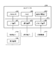
- FIG. 1 is a diagram showing a configuration example of an image compression system.
- FIG. 2 is a schematic diagram showing an example of compression processing.
- FIG. 3 is a schematic diagram showing an example of compression processing.
- FIG. 4 is a schematic diagram showing an example of compression processing.
- FIG. 5 is a block diagram showing a functional configuration example of an edge computer.
- FIG. 6 is a schematic diagram showing an example of generation of the first QP map.
- FIG. 7 is a schematic diagram showing an example of compression processing of an original image.
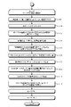
- FIG. 8 is a flowchart (1) showing the procedure of image processing.
- FIG. 9 is a flowchart (2) showing the procedure of image processing.
- FIG. 10 is a flowchart illustrating the procedure of image processing according to Application Example 1;
- FIG. 11 is a flowchart illustrating the procedure of image processing according to application example 2;
- FIG. 12 is a schematic diagram showing another example of compression processing of an original image.
- FIG. 13 is a diagram illustrating an example of
- FIG. 1 is a diagram showing a configuration example of an image compression system.
- the image compression system 1 shown in FIG. 1 compresses a plurality of original images captured by the imaging devices 3A to 3N and transmits them to the server device 50 via the network NW.
- the image compression system 1 may include an edge computer 10, imaging devices 3A to 3N, and a server device .
- imaging devices 3A to 3N may be referred to as "imaging device 3".
- the imaging device 3 has an imaging function of imaging an image.
- the imaging device 3 can capture moving images by capturing images in a specific frame cycle.
- an image captured by the imaging device 3 may be referred to as an "original image" in order to distinguish it from encoded data obtained by encoding or a decoded image obtained by decoding the encoded data.
- the imaging device 3 can be implemented by a camera, such as a surveillance camera, that has already been installed before the introduction of AI video analysis, from the aspect of increasing the motivation to introduce AI video analysis.
- a camera such as a surveillance camera
- the imaging devices 3A to 3N are implemented by surveillance cameras in this manner, the same subject, for example, an object targeted by video analysis by AI, is captured redundantly by a plurality of surveillance cameras in the imaging devices 3A to 3N. obtain.
- the edge computer 10 is a computer used for edge computing.
- the edge computer 10 corresponds to an example of an image processing device. This is merely an example, and other devices such as an IoT (Internet of Things) gateway can also correspond to the image processing device.
- the edge computer 10 includes image processing that performs compression processing to increase the compression rate between original images in which the same object is captured by the imaging device 3, as will be described later with reference to FIGS. function is installed. Compressed data compressed by such compression processing is transmitted to the server device 50 via the network NW.
- the server device 50 is an example of a computer that provides arbitrary services using compressed data of original images transmitted from the edge computer 10 .
- a service is an action recognition service using video analysis by AI.
- the behavior recognition service recognizes the behavior of an object to be analyzed from a video. For example, when the object to be analyzed is a "person", various behaviors such as work behavior, suspicious behavior, and purchasing behavior are to be analyzed.
- Objects to be analyzed are not limited to humans, and may be “animals” other than humans, such as zoo animals.
- the server device 50 can provide the above services by causing any computer to execute software that implements the functions corresponding to the above services.
- the server device 50 can be implemented as a server that provides the above services on-premises.
- the server device 50 can also provide the above service as a cloud service by implementing it as a SaaS (Software as a Service) type application.
- SaaS Software as a Service
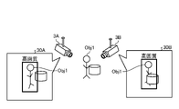
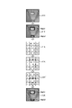
- FIG. 2 is a schematic diagram showing an example of compression processing.
- FIG. 2 shows an example in which an original image 30A captured by the imaging device 3A and an original image 30B captured by the imaging device 3B are compressed according to the prior art.
- the object Obj1 is captured by both the imaging device 3A and the imaging device 3B. Even in such a case, in the prior art, compression processing is performed for each of the original image 30A captured by the imaging device 3A and the original image 30B captured by the imaging device 3B.
- the area where the object Obj1 is recognized in the original image 30A is compressed with high image quality, and the other area is compressed with low image quality.
- the area where the object Obj1 is recognized in the original image 30B is compressed with high image quality, and the other area is compressed with low image quality.
- the object Ogj1 to be analyzed is duplicated between the imaging devices 3A and 3B and compressed to high image quality.
- the image processing function according to this embodiment solves the problem by an approach of compressing duplicated data to low image quality. That is, the image processing function according to the present embodiment selects an image to be compressed with high image quality for each object identified among a plurality of images captured by a plurality of cameras, and uses the selected image to compress the object. Compress the region to high quality.
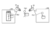
- FIG. 3 is a schematic diagram showing an example of compression processing.
- FIG. 3 shows an example in which an original image 30A captured by the imaging device 3A and an original image 30B captured by the imaging device 3B are compressed by the image processing function according to this embodiment.
- the image processing function selects which of the two images to compress the object Obj1 included in the original image 30A and the original image 30B to high image quality.
- the original image 30A in which no occlusion of the object Obj1 is detected is selected as the image for compressing the object Obj1 with high image quality.
- the area where the object Obj1 is recognized in the original image 30A is compressed with high image quality, and the other area is compressed with low image quality.
- the original image 30B is not selected as an image for compressing any object with high image quality. Therefore, the entire original image 30B is compressed with low image quality.
- the image processing function according to the present embodiment can prevent the analysis target object Ogj1 from being duplicated and compressed to high image quality between the imaging devices 3A and 3B. Therefore, the area of the object Obj1 of the original image 30B that does not contribute to video analysis by AI can be compressed with high image quality, and wasteful transmission via the network NW can be reduced.
- each image may include a plurality of objects.
- the image processing function selects an image to be compressed with high image quality for each object.
- the image processing function selects an image to be compressed with high image quality for each object.
- the reference technology that selects images by alternatives cannot select images that are more suitable for video analysis by AI for some objects regardless of which image is selected. Because you will get into trouble.
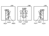
- FIG. 4 is a schematic diagram showing an example of compression processing.
- an original image 30A captured by the imaging device 3A, an original image 30B captured by the imaging device 3B, and an original image 30C captured by the imaging device 3C are compressed by the image processing function according to the present embodiment. Examples are given.
- objects Obj21 to Obj23 are imaged by three imaging devices 3A, 3B, and 3C.
- it is selected which of the three images of the objects Obj21 to Obj23 included in the original image 30A, the original image 30B, and the original image 30C is to be compressed with high image quality.
- the original image 30A is selected as the image for compressing the object Obj21 with high image quality.
- the original image 30B is selected as an image for compressing the object Obj22 with high image quality.
- the original image 30C is selected as an image for compressing the object Obj23 with high image quality.
- FIG. 5 is a block diagram showing a functional configuration example of the edge computer 10. As shown in FIG. FIG. 5 schematically shows blocks corresponding to image processing functions. As shown in FIG. 5 , the edge computer 10 has an acquisition unit 11 , a selection unit 12 , a setting unit 13 and a compression unit 14 .
- FIG. 5 only shows an excerpt of the functional units related to the image processing functions described above, and functions that existing edge computers are equipped with by default or as an option, such as filtering functions and security functions. do not interfere.
- the acquisition unit 11 is a processing unit that acquires the original image from the imaging device 3.
- the acquiring unit 11 can acquire the original images 30A to 30N frame by frame from the imaging devices 3A to 3N.
- the original images 30A to 30N may be referred to as "original images 30".
- the information source from which the acquisition unit 11 acquires the original image 30 may be any information source, and is not necessarily limited to the imaging devices 3A to 3N.
- the acquisition unit 11 may acquire the original image 30 from a storage connected to the edge computer 10 or a removable medium detachable from the edge computer 10 .
- the selection unit 12 is a processing unit that selects an image to be compressed with high image quality for each object included in the original image 30 acquired by the acquisition unit 11 .
- the selection unit 12 executes the following processing each time the acquisition unit 11 acquires a frame of the original images 30A to 30N. That is, the selection unit 12 executes object recognition for each original image 30 .
- object recognition can be realized by a machine learning model, such as a CNN (Convolutional Neural Network), in which objects have been trained according to a machine learning algorithm such as DL (Deep Learning).
- a machine learning model outputs the area where the object exists, such as the bounding box, as well as the class of the object.
- an identified object can be identified by matching the position, size, similarity, feature points, etc. of the object between a plurality of original images 30A-30N using known techniques.
- the selection unit 12 repeats the process of selecting the original image 30 in which the area corresponding to the identified object is compressed with high image quality a number of times corresponding to the number L of the identified objects included in the original images 30A to 30N. .
- the selection criteria for selecting the original image 30 include at least one of the degree of occlusion of the identified object, such as the presence or absence and ratio, the size of the identified object, the output of the machine learning model, and the probability of the class, for example. can be used.
- the degree of occlusion of the identified object such as the presence or absence and ratio
- the size of the identified object such as the output of the machine learning model
- the probability of the class for example.
- an original image 30 with no occlusion or a low occlusion ratio, a large image size, and a high class probability is more likely to be selected.
- an original image 30 with occlusion or a high occlusion ratio, a small image size, and a low class probability is less likely to be selected.
- the setting unit 13 is a processing unit that sets the compression rate of the original image 30 .
- Threads for the compression unit 14 may be generated for parallel processing.
- the setting unit 13 resizes the original image 30 acquired by the acquisition unit 11 according to the input size of the machine learning model used by the service execution unit 51 of the server device 50 .
- the action recognition service uses a DL framework including object recognition and skeleton detection.
- the size of the original image 30 is resized according to the size of the YOLO model used for object recognition.
- the setting unit 13 inputs the resized original image 30 to a machine learning model similar to the machine learning model executed by the service execution unit 51 of the server device 50, and outputs the machine learning model obtained as a teacher. , is set as a so-called correct label. Then, the setting unit 13 encodes the original image 30 after resizing according to the QP value for each value of the quantization parameter (QP), and decodes the encoded data to obtain a decoded image. to generate For example, if the range from the lower limit value to the upper limit value of QP is 0 to 51, a decoded image is generated for each QP value from QP1 to QP51.
- QP quantization parameter
- the setting unit 13 executes BP (Back Propagation) calculation based on the error between the correct label and the output of the machine learning model to which the decoded image obtained for each QP value is input.
- the BP calculation can be performed according to the BP method, the GBP (Guided Back Propagation) method, the selective BP method, or the like.
- the BP calculation includes layer structures such as neurons and synapses of each layer of the input layer, hidden layer, and output layer of the machine learning model of the service execution unit 51, as well as models such as parameters such as weights and biases of each layer. of structural information is used.
- an influence map is obtained for each QP value in which the influence of each pixel of the decoded image on video analysis realized by the machine learning model of the service execution unit 51, such as object recognition by the YOLO model, is mapped.
- the setting unit 13 divides each of the influence maps obtained for each QP value into blocks of the encoding unit of the encoding method applied to the compression unit 14, and divides each block into pixels included in the block. By aggregating the degree of influence of each block, the aggregate value of the degree of influence is calculated for each block. Furthermore, the setting unit 13 generates an influence graph for each block by associating the relationship between the aggregate value of the influence and the QP value for each same block. Then, the setting unit 13 generates a first QP map in which QP values used for quantization of each block are mapped based on the influence graph generated for each block.
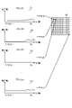
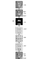
- FIG. 6 is a schematic diagram showing an example of generating the first QP map.
- FIG. 6 shows influence graphs G1 to Gm for m blocks from block 1 to block m.
- the vertical axis of the influence degree graphs G1 to Gm shown in FIG. 6 indicates the aggregate value of the influence degree
- the horizontal axis indicates the QP value.
- Influence graphs G1 to Gm shown in FIG. 6 are generated by plotting aggregated values of influence for each QP value for blocks 1 to m.
- FIG. 6 shows an example in which blocks 1 to m are of the same size, the size of each block may be variable depending on the encoding method.
- the aggregate value of each QP value of each block used to generate the influence graphs G1 to Gm is - It may be adjusted using an offset value common to all blocks. - The absolute value may be taken and aggregated. - The aggregate values of other blocks may be processed based on the aggregate values of blocks that have not received attention.
- the setting unit 13 ⁇ When the size of the aggregated value exceeds the threshold, or ⁇ If the amount of change in the aggregate value exceeds the threshold, or ⁇ If the slope of the aggregate value exceeds the threshold, or ⁇ If the change in the slope of the aggregate value exceeds the threshold, is satisfied, determine the optimum QP value for each block and generate a first QP map.
- the first QP map 40 shows how B 1 Q to B m Q are determined as optimal quantization values for blocks 1 to m and set to the corresponding blocks, respectively.
- the setting unit 13 determines the QP value as follows, for example. ⁇ When the size of the block used for compression processing is larger than the size of the block used for aggregation The average QP value (or (minimum value, maximum value, value processed by other indices) is used as the QP value of each block used for compression processing. ⁇ When the size of the block used for compression processing is smaller than the size of the block used for aggregation The total value of the blocks used for aggregation is used as the QP value of each block used for compression processing, which is included in the block used for aggregation. using the QP value based on
- the process of actually deriving the total value may be obtained from only one QP value (image quality deterioration state of one image).
- different QP values image quality deterioration states of different images
- the assumed QP value image quality deterioration state of a different image
- the assumed QP value image quality deterioration state of a different image
- the assumed QP value image quality deterioration state of a different image
- the assumed QP value image quality deterioration state of a different image
- the decoded data of the data actually encoded with the QP value may be used, or image processing (for example, low-pass filter, etc.) that produces the same effect may be applied.
- the threshold applied when evaluating the aggregate value graph may or may not be different for each block, and may or may not be adjusted, for example, by the inference score value.
- the threshold is automatically obtained from the information obtained during inference and information from images, or statistics using them, the amount and transition of encoded data, or other information that can be obtained from the content of processing. It may be determined, it may be determined based on information acquired in advance by a learning method or statistical means in advance, or it may be determined by other means.
- the setting unit 13 sets, in the first QP map, blocks included in the bounding box of the object recognized in the original image 30 to be processed as foreground blocks. Further, the setting unit 13 sets blocks other than the blocks set as foreground blocks in the first QP map as background blocks.
- the setting unit 13 sets, among the foreground blocks, the foreground blocks corresponding to the identified objects for which the original image 30 to be processed is not selected by the selection unit 12 as background blocks. As a result, blocks corresponding to identified objects that are not subject to video analysis are set as background blocks. Then, the setting unit 13 maximizes the QP value of the block set as the background block among the QP values set for each block. As a result, a second QP map is generated that includes the QP values set for the foreground blocks and the QP values set for the background blocks, for example, the maximum "51".
- the setting unit 13 sets the confidence level output by the machine learning model when the decoded image is input as follows under the constraint condition that the confidence level is an allowable range from the reference confidence level output by the machine learning model when the original image 30 is input. process. That is, the setting unit 13 executes clip processing in which the QP values of the second QP map are decreased in order from the maximum QP value and the QP values are increased in order from the minimum QP value. A QP map is output to the compression unit 14 .
- the compression unit 14 is a processing unit that compresses the original image 30 at the compression ratio set by the setting unit 13. As an example only, the compression unit 14 generates compressed data by encoding the original image 30 according to the second QP map generated by the setting unit 13 .
- the compression unit 14 uses MPEG-2, MPEG-4, H.264, and MPEG-2. Any coding scheme can be used, such as H.264, HEVC, or VVC.
- FIG. 7 is a schematic diagram showing an example of compression processing of an original image.
- FIG. 7 schematically shows the compression processing performed on the original image 31A captured by the imaging device 3A as an example only.
- two hanging clocks are recognized as identified objects Obj31 and Obj32 from the original image 31A.
- the original image 31A is resized according to the input size of the machine learning model executed by the service execution unit 51 of the server device 50.
- FIG. After resizing, the original image 31A is input to a machine learning model similar to the machine learning model used by the service execution unit 51 of the server device 50, and the output of the machine learning model obtained is set as the correct label.
- BP calculation is performed based on the error between the correct label and the output of the machine learning model to which the decoded image generated for each QP value is input.
- an influence map is obtained for each QP value in which the influence of each pixel of the decoded image on video analysis realized by the machine learning model of the service execution unit 51, such as object recognition by the YOLO model, is mapped.
- each of the influence maps obtained for each QP value is divided into blocks of coding units, and the influence of pixels included in the block is aggregated for each block.
- an influence graph is generated.
- a first QP map 41A is generated in which QP values used for quantization of each block are mapped based on the influence graph generated for each block.
- blocks included in the bounding boxes of the identified objects Obj31 and Obj32 recognized in the original image 30A to be processed are set as foreground blocks.
- the blocks corresponding to the bounding box of the identified object Obj31 the block at the 2nd row and the 2nd column and the block at the 2nd row and the 3rd column are set as the foreground blocks.
- the blocks corresponding to the bounding box of the identified object Obj32 the block at the 4th row, the 2nd column and the block at the 4th row, the 3rd column are set as the foreground blocks.
- blocks other than the blocks set as foreground blocks are set as background blocks.
- the foreground block corresponding to the identified object for which the original image 31A to be processed is not selected is set as the background block.
- the original image 31A is selected as an image for compressing the identified object Obj31 with high image quality
- the original image 31A is selected as an image for compressing the identified object Obj32 with high image quality
- block reconstruction from the foreground to the background is performed. No settings are executed.
- the QP value of the block set as the background block is maximized.
- the QP values of the blocks other than the 2nd row, 2nd column block, the 2nd row, 3rd column block, the 4th row, 2nd column block, and the 4th row, 3rd column block are maximized. be.
- the QP values of the block at row 1, column 2, the block at row 1, column 3, and the block at row 3, column 3, which did not have the maximum value are changed to 51. Thereby, the second QP map 42A is generated.
- the following processing is executed under the constraint that the confidence level output by the machine learning model when the decoded image is input is within the allowable range from the reference confidence level output by the machine learning model when the original image 31A is input. be. That is, a clip process is performed in which the QP values of the second QP map 42A are decreased in order from the maximum QP value and the QP values are increased in order from the minimum QP value.
- the QP value is changed from "45" to Downgraded to "30".
- the QP value is increased from “20” to “47” for the second row, second column block having the minimum QP value of "20” in the second QP map 42A.
- the QP value is raised from "22" to "47” for the second row, third column block having the second smallest QP value "22" in the second QP map 42A.
- Compressed data of the original image 31A is generated by encoding the original image 31A according to the second QP map 42A' after clip processing. When the compressed data of such original image 31A is decoded, it becomes a decoded image 43A.
- FIG. 7 shows an example in which the original image 31A is selected as an image for compressing the identified object Obj31 with high image quality, and the original image 31A is selected as an image for compressing the identified object Obj32 with high image quality. listed in If the original image 31A is not selected as the image for compressing the identified object Obj31 with high image quality, the foreground blocks corresponding to the identified object Obj31, ie, the block at the second row and the second column and the block at the second row and the third column are Resets to background block.
- the foreground blocks corresponding to the identified object Obj32 ie, the block at the 4th row, the 2nd column and the block at the 4th row, the 3rd column, are Resets to background block.
- ⁇ Process flow> 8 and 9 are flowcharts showing the procedure of image processing. As shown in FIGS. 8 and 9, as an example only, as long as new frames of the original images 30A to 30N are acquired by the acquisition unit 11, loop processing 1 is executed to repeat the processing from step S101 to step S114. .
- the acquiring unit 11 acquires original images 30A to 30N of new frames from the imaging devices 3A to 3N (step S101). Subsequently, the selection unit 12 recognizes objects included in the original images 30A to 30N by executing object recognition for each original image 30 (step S102).
- the selection unit 12 selects the original image 30 in which the regions corresponding to the identified objects are compressed with high image quality the number of times corresponding to the number L of the identified objects among the objects recognized from the original images 30A to 30N.
- a loop process 2 that repeats the process (step S103) is executed.
- the setting unit 13 and the compression unit 14 execute a loop process 3 that repeats the processes from step S104 to step S114 below for the number of times corresponding to the number N of original images 30 .
- the setting unit 13 resizes the original image 30 acquired in step S101 according to the input size of the machine learning model used by the service execution unit 51 of the server device 50 (step S104).
- the setting unit 13 inputs the resized original image 30 to a machine learning model similar to the machine learning model used by the service execution unit 51 of the server device 50, and uses the output of the machine learning model as the correct label.
- Set step S105.
- the setting unit 13 encodes the resized original image 30 according to each QP value and decodes the encoded data to generate a decoded image (step S106).
- the setting unit 13 executes BP calculation based on the error between the correct label and the output of the machine learning model to which the decoded image obtained for each QP value is input (step S107).
- an influence map is obtained for each QP value in which the influence of each pixel of the decoded image on video analysis realized by the machine learning model of the service execution unit 51, such as object recognition by the YOLO model, is mapped.
- the setting unit 13 divides each of the influence maps obtained for each QP value into blocks of the encoding unit of the encoding method applied to the compression unit 14, and divides each block into pixels included in the block. Aggregate the impact of Furthermore, the setting unit 13 generates an influence graph for each block by associating the relationship between the aggregate value of the influence and the QP value for each same block (step S108).
- the setting unit 13 generates a first QP map in which QP values used for quantization of each block are mapped based on the influence graph generated for each block in step S108 (step S109).
- the setting unit 13 sets blocks included in the bounding box of the object recognized in the original image 30 being loop-processed in the first QP map as foreground blocks. Further, the setting unit 13 sets blocks other than the blocks set as the foreground blocks in the first QP map as background blocks (step S110).
- the setting unit 13 resets, among the foreground blocks, the foreground blocks corresponding to the identified objects for which the original image 30 being loop-processed is not selected in step S110 as background blocks (step S111).
- the setting unit 13 maximizes the QP value of the block set as the background block among the QP values of each block included in the first QP map (step S112).
- a second QP map is generated that includes the QP values set for the foreground blocks and the QP values set for the background blocks, for example, the maximum "51".
- the setting unit 13 sets the confidence level output by the machine learning model when the decoded image is input as follows under the constraint condition that the confidence level is an allowable range from the reference confidence level output by the machine learning model when the original image 30 is input. process. That is, the setting unit 13 performs clip processing for decreasing the QP values in order from the maximum QP value in the second QP map and increasing the QP values in order from the minimum QP value (step S113).
- the compression unit 14 generates compressed data by encoding the original image 30 being loop-processed according to the second QP map generated in step S113 (step S114), and ends the process.
- the edge computer 10 selects an image to be compressed with high image quality for each object identified among a plurality of images captured by a plurality of cameras, and compresses the selected image. to compress the area of the object to high image quality. For this reason, it is possible to compress the object region to low image quality using images that are not selected for use in video analysis. Therefore, according to the edge computer 10 of this embodiment, it is possible to reduce the amount of data to be transmitted or recorded.
- ⁇ Application example 1> In the above-described first embodiment, an example was given in which the other identified objects other than the area of the identified object for which compression with high image quality was selected in the original image were compressed to low image quality. A reduction in the amount of data can also be achieved.
- the setting unit 13 sets the error between the region of the identified object not selected for use in the video analysis realized by the machine learning model of the service execution unit 51 and the correct label to be equal to or less than the threshold, and calculates the BP. can also be executed.
- the QP value of the block is set smaller as the influence degree or the increment of the influence degree with respect to the increase of the QP value is larger, and the QP value of the block is set larger as the influence degree or the increment of the influence degree with respect to the increase of the QP value is smaller.
- a first QP map generation algorithm is used. For this reason, the maximum QP value is likely to be set to a block to which an area in which the error is set to a threshold value or less, for example zero, belongs.
- FIG. 10 is a flowchart showing the procedure of image processing according to Application Example 1.
- FIG. 10 different step numbers are given to different processes from the flowchart shown in FIG. 9, while the same step numbers are given to the same processes as in the flowchart shown in FIG. In addition, below, the difference between the flowchart shown in FIG. 10 and the flowchart shown in FIG. 9 is demonstrated.
- the flowchart shown in FIG. 10 differs in that the process of step S201 is executed instead of the process of step S107 shown in FIG. 9 and that the process of step S111 shown in FIG. 9 can be skipped.
- step S106 the setting unit 13 sets the error between the region of the identified object not selected for video analysis and the correct label to zero, and BP calculation is executed with the decoded image obtained in (step S201).
- the maximum QP value "51" can be set to the block corresponding to the area of the identified object that has not been selected for video analysis. can be skipped.
- the setting unit 13 masks areas other than the area of the identified object selected for video analysis in the original image and the area of the non-identified object included only in the original image. Further, the setting unit 13 sets blocks corresponding to the mask region as background blocks when generating the first QP map.
- FIG. 11 is a flowchart showing the procedure of image processing according to Application Example 2.
- FIG. 11 different step numbers are given to different processes from those in the flowchart shown in FIG. 9, while the same step numbers are given to the same processes as in the flowchart shown in FIG.
- the difference between the flowchart shown in FIG. 11 and the flowchart shown in FIG. 9 is demonstrated.
- step S301 is inserted before the processing of step S104 shown in FIG. 9, and the processing of step S302 is performed instead of the processing of steps S110 and S111 shown in FIG. is executed.
- the setting unit 13 masks the area of the original image 30 being loop-processed, other than the area of the identified object selected for video analysis (step S301). ). After that, after the process of step S109, the setting unit 13 sets the QP value of the block corresponding to the region masked in step S301 in the first QP map to a specific value, for example, the maximum value, thereby obtaining the second QP value.
- a QP map is generated (step S302).
- the maximum QP value "51" can be set for blocks corresponding to areas not selected for video analysis.
- FIG. 12 is a schematic diagram showing another example of compression processing of an original image.
- FIG. 12 schematically shows the compression processing performed on the original image 31A captured by the imaging device 3A as an example only.
- two hanging clocks are recognized as identified objects Obj31 and Obj32 from the original image 31A.
- the original image 31A is selected as the image for compressing the identified object Obj31 with high image quality
- the original image 31A is selected as the image for compressing the identified object Obj32 with high image quality.
- the area selected for video analysis that is, the area other than the area of the identified object Obj31 and the area of the identified object Obj32 is masked as the mask area ME.
- the masked original image 31A is resized according to the input size of the machine learning model used by the service execution unit 51 of the server device 50 .
- the original image 31A is input to a machine learning model similar to the machine learning model executed by the service execution unit 51 of the server device 50, and the output of the machine learning model obtained is set as the correct label.
- BP calculation is performed based on the error between the correct label and the output of the machine learning model to which the decoded image generated for each QP value is input. At this time, the BP calculation of the mask area ME in the decoded image is skipped.
- an influence map is obtained in which the influence of each pixel of the decoded image other than the mask area ME on the video analysis realized by the machine learning model of the service execution unit 51, for example, the object recognition by the YOLO model is mapped. obtained for each QP value.
- each of the influence maps obtained for each QP value is divided into blocks of coding units, and the influence of pixels included in the block is aggregated for each block.
- an influence graph is generated.
- a first QP map 41A1 is generated in which QP values used for quantization of each block are mapped based on the influence graph generated for each block.
- the BP calculation is skipped and the degree of influence is not calculated. Therefore, an asterisk indicates that there is no value of the degree of influence.
- the second QP map 42A is generated by setting the QP value of the block corresponding to the mask area ME in the first QP map 41A1 to a specific value, for example, the maximum value.
- a specific value for example, the maximum value.
- the QP values of the blocks at column 4, row 4, column 1 and row 4, column 4 are maximized. Thereby, the second QP map 42A is generated.
- the following processing is executed under the constraint that the confidence level output by the machine learning model when the decoded image is input is within the allowable range from the reference confidence level output by the machine learning model when the original image 31A is input. be. That is, a clip process is performed in which the QP values of the second QP map 42A are decreased in order from the maximum QP value and the QP values are increased in order from the minimum QP value.
- the QP value is changed from "45" to Downgraded to "30".
- the QP value is increased from “20” to “47” for the second row, second column block having the minimum QP value of "20” in the second QP map 42A.
- the QP value is raised from "22" to "47” for the second row, third column block having the second smallest QP value "22" in the second QP map 42A.
- Compressed data of the original image 31A is generated by encoding the original image 31A according to the second QP map 42A' after clip processing. When the compressed data of such original image 31A is decoded, it becomes a decoded image 43A.
- each component of each illustrated device does not necessarily have to be physically configured as illustrated.
- the specific form of distribution and integration of each device is not limited to the one shown in the figure, and all or part of them can be functionally or physically distributed and integrated in arbitrary units according to various loads and usage conditions. Can be integrated and configured.
- the acquisition unit 11, the selection unit 12, the setting unit 13, or the compression unit 14 may be connected to the edge computer 10 via a network as external devices.
- the functions of the edge computer 10 may be realized by having different devices each having the acquisition unit 11, the selection unit 12, the setting unit 13, or the compression unit 14, and connected to a network to cooperate with each other. good.
- FIG. 13 is a diagram illustrating an example of a hardware configuration
- the computer 200 has a processor 201 , a memory 202 , an auxiliary storage device 203 , an I/F (Interface) device 204 , a communication device 205 and a drive device 206 .
- Each piece of hardware of the computer 200 is interconnected via a bus 207 .
- the processor 201 has various computing devices such as a CPU (Central Processing Unit) and a GPU (Graphics Processing Unit).
- the processor 201 reads the above image processing program and the like onto the memory 202 and executes them.
- the memory 202 has main storage devices such as ROM (Read Only Memory) and RAM (Random Access Memory).
- the processor 201 executes the image processing program read on the memory 202, so that the computer 200 performs image processing functions corresponding to the acquisition unit 11, the selection unit 12, the setting unit 13, and the compression unit 14 shown in FIG. Realize
- the auxiliary storage device 203 stores various programs and various data used when the various programs are executed by the processor 201 .
- the I/F device 204 is a connection device that connects the operation device 210 and the display device 220, which are examples of external devices, and the computer 200.
- the I/F device 204 receives operations for the computer 200 via the operation device 210 .
- the I/F device 204 also outputs the results of processing by the computer 200 and displays them via the display device 220 .
- the communication device 205 is a communication device for communicating with other devices. For example, it communicates with imaging devices 3A to 3N and the server device 50, which are other devices, via the communication device 205.
- FIG. 1 A communication device for communicating with other devices. For example, it communicates with imaging devices 3A to 3N and the server device 50, which are other devices, via the communication device 205.
- FIG. 1 A communication device for communicating with other devices. For example, it communicates with imaging devices 3A to 3N and the server device 50, which are other devices, via the communication device 205.
- a drive device 206 is a device for setting a recording medium 230 .
- the recording medium 230 here includes media for optically, electrically or magnetically recording information such as a CD-ROM, a flexible disk, a magneto-optical disk, and the like.
- the recording medium 230 may also include a semiconductor memory or the like that electrically records information, such as a ROM or flash memory.
- auxiliary storage device 203 can be installed, for example, by setting the distributed recording medium 230 in the drive device 206 and reading the image processing program recorded in the recording medium 230 by the drive device 206. Installed. Alternatively, various programs installed in the auxiliary storage device 203 may be installed by being downloaded from the network via the communication device 205 .
Landscapes
- Engineering & Computer Science (AREA)
- Multimedia (AREA)
- Signal Processing (AREA)
- Compression Or Coding Systems Of Tv Signals (AREA)
Abstract
画像処理装置は、複数の撮像装置ごとに画像を取得し、複数の撮像装置ごとに取得された複数の画像の間で同定された同定オブジェクトごとに第1の画質よりも高い第2の画質で圧縮する画像を選択し、該選択された画像で同定オブジェクトの領域を第2の画質で圧縮する、処理を実行する制御部を含む。
Description
本発明は、画像処理技術に関する。
一般に、画像データを記録または伝送する際には、画像データに対して圧縮処理を行い、データサイズを小さくすることで、記録コストの削減や伝送コストの削減を実現している。
一方で、近年、AI(Artificial Intelligence)による映像解析に利用される目的で、画像データを記録または伝送するケースが増えてきている。AIの代表的なモデルとして、例えば、深層学習や機械学習を用いたモデルが挙げられる。例えば、カメラで撮像される画像のうち解析対象のオブジェクトのみを高画質に圧縮する技術がある。
しかしながら、上記の従来技術では、同一の対象が複数のカメラで撮像される場合でも各カメラで撮像される画像ごとに圧縮処理が行われる。この場合、解析対象のオブジェクトが重複して高画質に圧縮されるので、AIによる映像解析に寄与しないカメラの画像まで高画質に圧縮される結果、クラウド等の伝送先に無駄なデータが伝送される。
1つの側面では、本発明は、伝送又は記録のデータ量の削減を実現できる画像処理装置、画像処理方法及び画像処理プログラムを提供することを目的とする。
一態様の画像処理装置は、複数の撮像装置ごとに画像を取得し、前記複数の撮像装置ごとに取得された複数の画像の間で同定された同定オブジェクトごとに第1の画質よりも高い第2の画質で圧縮する画像を選択し、該選択された画像で前記同定オブジェクトの領域を前記第2の画質で圧縮する、処理を実行する制御部を含む。
伝送又は記録のデータ量の削減を実現できる。
以下、添付図面を参照して本願に係る画像処理装置、画像処理方法及び画像処理プログラムの実施例について説明する。各実施例には、あくまで1つの例や側面を示すに過ぎず、このような例示により数値や機能の範囲、利用シーンなどは限定されない。そして、各実施例は、処理内容を矛盾させない範囲で適宜組み合わせることが可能である。
<システム構成>
図1は、画像圧縮システムの構成例を示す図である。図1に示す画像圧縮システム1は、撮像装置3A~3Nにより撮像される複数のオリジナル画像を圧縮してネットワークNWを介してサーバ装置50へ伝送するものである。
図1は、画像圧縮システムの構成例を示す図である。図1に示す画像圧縮システム1は、撮像装置3A~3Nにより撮像される複数のオリジナル画像を圧縮してネットワークNWを介してサーバ装置50へ伝送するものである。
図1に示すように、画像圧縮システム1には、エッジコンピュータ10と、撮像装置3A~3Nと、サーバ装置50とが含まれ得る。以下、撮像装置3A~3Nのことを「撮像装置3」と記載する場合がある。
撮像装置3は、画像を撮像する撮像機能を有する。1つの側面として、撮像装置3は、特定のフレーム周期で画像を撮影することにより動画を撮像することができる。以下、撮像装置3により撮像される画像を符号化により得られた符号化データや符号化データが復号化された復号画像と区別する側面から、「オリジナル画像」と記載する場合がある。
あくまで一例として、撮像装置3は、AIによる映像解析の導入のモチベーションを高める側面から、AIによる映像解析の導入前に設置済みであるカメラ、例えば監視カメラ等により実現され得る。このように撮像装置3A~3Nが監視カメラにより実現される場合、撮像装置3A~3Nでは、同一の被写体、例えばAIによる映像解析で対象とされるオブジェクトが複数の監視カメラで重複して撮像され得る。
エッジコンピュータ10は、エッジコンピューティングに用いられるコンピュータである。エッジコンピュータ10は、画像処理装置の一例に対応する。これはあくまで一例であってIoT(Internet of Things)ゲートウェイなどの他の装置も画像処理装置に対応し得る。1つの側面として、エッジコンピュータ10には、図2~図4を用いて後述する通り、撮像装置3により同一のオブジェクトが撮像されたオリジナル画像の間で圧縮率を高める圧縮処理を実行する画像処理機能が搭載される。このような圧縮処理で圧縮された圧縮データがネットワークNWを介してサーバ装置50へ伝送される。
サーバ装置50は、エッジコンピュータ10から伝送されるオリジナル画像の圧縮データを用いた任意のサービスを提供するコンピュータの一例である。例えば、サービスの例として、AIによる映像解析を用いる行動認識サービスが挙げられる。行動認識サービスでは、映像から解析対象とするオブジェクトの行動が認識される。例えば、解析対象とするオブジェクトが「人」である場合、作業行動や不審行動、購買行動などの各種の行動が解析対象とされる。なお、解析対象とするオブジェクトは、人に限らず、人以外の「動物」、例えば動物園の動物などであってもよい。
あくまで一例として、サーバ装置50は、上記のサービスに対応する機能を実現するソフトウェアを任意のコンピュータに実行させることにより上記のサービスを提供できる。一例として、サーバ装置50は、上記のサービスをオンプレミスに提供するサーバとして実装することができる。他の一例として、サーバ装置50は、SaaS(Software as a Service)型のアプリケーションとして実装することで、上記のサービスをクラウドサービスとして提供することもできる。
<課題の一側面>
AIによる映像解析に用いられるカメラの増加に伴って動画データの数も増加し、通信や記録のコストが増大している側面がある。
AIによる映像解析に用いられるカメラの増加に伴って動画データの数も増加し、通信や記録のコストが増大している側面がある。
このような側面から、背景技術の欄で挙げた従来技術の通り、AIによる映像解析で使用に耐える最低限の画質まで圧縮率を高めて画像が圧縮されているが、依然として、通信や記録のコストの増大は抑制できていない現状がある。
図2は、圧縮処理の一例を示す模式図である。図2には、従来技術に従って撮像装置3Aにより撮像されるオリジナル画像30Aおよび撮像装置3Bにより撮像されるオリジナル画像30Bが圧縮される例が示されている。
図2に示すように、オブジェクトObj1は、撮像装置3A及び撮像装置3Bの両方で撮像される。このような場合においても、従来技術では、撮像装置3Aで撮像されるオリジナル画像30A及び撮像装置3Bで撮像されるオリジナル画像30Bごとに圧縮処理が行われる。
例えば、オリジナル画像30AのうちオブジェクトObj1が認識された領域が高画質で圧縮されると共に、他の領域が低画質で圧縮される。また、オリジナル画像30BのうちオブジェクトObj1が認識された領域が高画質で圧縮されると共に、他の領域が低画質で圧縮される。このように、上記の従来技術では、撮像装置3Aおよび撮像装置3Bの間で解析対象のオブジェクトOgj1が重複して高画質に圧縮される。
ところが、AIによる映像解析では、オリジナル画像30Aの圧縮データおよびオリジナル画像30Bの圧縮データの両方が必ずしも必要とされない場合がある。図2に示す例で言えば、オリジナル画像30Aでは、オブジェクトObj1の全身が撮像される。その一方で、オリジナル画像30Bでは、オブジェクトObj1の下半身が椅子などの物体で遮られた状態で撮影されるので、オブジェクトObj1の下半身にオクルージョンが発生する。この場合、オリジナル画像30Bの圧縮データがネットワークNWを介して伝送されたとしてもAIによる映像解析に寄与しないので、オブジェクトObj1を高画質で圧縮して伝送したとしても無駄になる可能性が高い。
<課題解決アプローチの一側面>
そこで、本実施例に係る画像処理機能は、重複データを低画質に圧縮するというアプローチにより課題を解決する。すなわち、本実施例に係る画像処理機能は、複数のカメラで撮像された複数の画像の間で同定されたオブジェクトごとに高画質で圧縮する画像を選択し、該選択された画像で当該オブジェクトの領域を高画質に圧縮する。
そこで、本実施例に係る画像処理機能は、重複データを低画質に圧縮するというアプローチにより課題を解決する。すなわち、本実施例に係る画像処理機能は、複数のカメラで撮像された複数の画像の間で同定されたオブジェクトごとに高画質で圧縮する画像を選択し、該選択された画像で当該オブジェクトの領域を高画質に圧縮する。
図3は、圧縮処理の一例を示す模式図である。図3には、本実施例に係る画像処理機能により、撮像装置3Aにより撮像されるオリジナル画像30Aおよび撮像装置3Bにより撮像されるオリジナル画像30Bが圧縮される例が示されている。
図3に示すように、画像処理機能は、オリジナル画像30Aおよびオリジナル画像30Bに含まれるオブジェクトObj1を2つの画像のうちいずれの画像で高画質に圧縮するのかを選択する。図3に示す例で言えば、オブジェクトObj1を高画質に圧縮する画像として、オブジェクトObj1のオクルージョンが検出されないオリジナル画像30Aが選択される。これにより、オリジナル画像30AのうちオブジェクトObj1が認識された領域が高画質で圧縮されると共に、他の領域が低画質で圧縮される。一方、オリジナル画像30Bは、いずれのオブジェクトを高画質で圧縮する画像として選択されていない。このため、オリジナル画像30B全体が低画質で圧縮される。
このように、本実施例に係る画像処理機能では、撮像装置3Aおよび撮像装置3Bの間で解析対象のオブジェクトOgj1が重複して高画質に圧縮されるのを抑制できる。このため、AIによる映像解析に寄与しないオリジナル画像30BのオブジェクトObj1の領域が高画質で圧縮されると共にネットワークNWを介して伝送される無駄を削減できる。
したがって、本実施例に係る画像処理機能によれば、伝送又は記録のデータ量の削減を実現できる。なお、図3には、オリジナル画像30Aおよびオリジナル画像30Bに含まれるオブジェクトがオブジェクトObj1の1つである例を挙げたが、当然のことながら、各画像に含まれるオブジェクトは複数であってよい。
1つの側面として、本実施例に係る画像処理機能は、オブジェクトごとに高画質に圧縮する画像を選択するので、複数の撮像装置により撮像された画像のうち1つの画像を択一で選択する参考技術とは区別される。なぜなら、AIによる映像解析に適する画像がオブジェクトによって異なる場合、択一で画像を選択する参考技術では、いずれの画像が選択されたとしても一部のオブジェクトでAIによる映像解析により適する画像を選択できない事態に陥るからである。
図4は、圧縮処理の一例を示す模式図である。図4には、本実施例に係る画像処理機能により、撮像装置3Aにより撮像されるオリジナル画像30A、撮像装置3Bにより撮像されるオリジナル画像30Bおよび撮像装置3Cにより撮像されるオリジナル画像30Cが圧縮される例が示されている。
図4に示すように、オブジェクトObj21~Obj23は、撮像装置3A、撮像装置3Bおよび撮像装置3Cの3つで撮像される。この場合、オリジナル画像30A、オリジナル画像30Bおよびオリジナル画像30Cに含まれるオブジェクトObj21~Obj23を3つの画像のうちいずれの画像で高画質に圧縮するのかを選択する。図4に示す例で言えば、オブジェクトObj21を高画質に圧縮する画像として、オリジナル画像30Aが選択される。さらに、オブジェクトObj22を高画質に圧縮する画像として、オリジナル画像30Bが選択される。さらに、オブジェクトObj23を高画質に圧縮する画像として、オリジナル画像30Cが選択される。このように、AIによる映像解析に適する画像がオブジェクトObj21~23によって異なる場合でも、オブジェクトObj21~23ごとにAIによる映像解析に適する画像を選択できる。
<エッジコンピュータ10の構成>
図5は、エッジコンピュータ10の機能構成例を示すブロック図である。図5には、画像処理機能に対応するブロックが模式化されている。図5に示すように、エッジコンピュータ10は、取得部11と、選択部12と、設定部13と、圧縮部14とを有する。
図5は、エッジコンピュータ10の機能構成例を示すブロック図である。図5には、画像処理機能に対応するブロックが模式化されている。図5に示すように、エッジコンピュータ10は、取得部11と、選択部12と、設定部13と、圧縮部14とを有する。
これら取得部11、選択部12、設定部13および圧縮部14などの機能部は、CPU(Central Processing Unit)やGPU(Graphics Processing Unit)などのハードウェアプロセッサにより仮想的に実現される。なお、図5には、上記の画像処理機能に関連する機能部が抜粋して示されているに過ぎず、フィルタリング機能やセキュリティ機能などの既存のエッジコンピュータがデフォルトまたはオプションで装備する機能が備わることを妨げない。
取得部11は、撮像装置3からオリジナル画像を取得する処理部である。あくまで一例として、取得部11は、撮像装置3A~3Nからオリジナル画像30A~30Nをフレーム単位で取得することができる。以下、オリジナル画像30A~30Nのことを「オリジナル画像30」と記載する場合がある。ここで、取得部11がオリジナル画像30を取得する情報ソースは、任意の情報ソースであってよく、必ずしも撮像装置3A~3Nに限定されない。例えば、取得部11は、エッジコンピュータ10に接続されたストレージ、あるいはエッジコンピュータ10に着脱可能なリムーバブルメディアなどからオリジナル画像30を取得することとしてもよい。
選択部12は、取得部11により取得されたオリジナル画像30に含まれるオブジェクトごとに高画質で圧縮する画像を選択する処理部である。あくまで一例として、選択部12は、取得部11によりオリジナル画像30A~30Nのフレームが取得される度に、次のような処理を実行する。すなわち、選択部12は、オリジナル画像30ごとに当該オリジナル画像30に対するオブジェクト認識を実行する。このようなオブジェクト認識のアルゴリズムの一例として、YOLO(You Only Look Once)などを適用できる。例えば、YOLOの場合、オブジェクト認識は、DL(Deep Learning)などの機械学習アルゴリズムに従ってオブジェクトが訓練済みである機械学習モデル、例えばCNN(Convolutional Neural Network)により実現され得る。このような機械学習モデルは、オリジナル画像30が入力されることにより、オブジェクトが存在する領域、例えばバウンディングボックスの他、オブジェクトのクラスなどを出力する。
これにより、オリジナル画像30A~30Nに含まれるオブジェクトが認識される。このようにオリジナル画像30A~30Nの各々で認識されるオブジェクトのうち少なくとも2つ以上のオリジナル画像で同定される同定オブジェクトを識別する。例えば、同定オブジェクトの識別は、公知の技術を用いて、オブジェクトの位置や大きさ、類似度、特徴点などを複数のオリジナル画像30A~30Nの間でマッチングすることにより同定できる。
続いて、選択部12は、オリジナル画像30A~30Nに含まれる同定オブジェクトの個数Lに対応する回数の分、当該同定オブジェクトに対応する領域を高画質で圧縮するオリジナル画像30を選択する処理を繰り返す。
ここで、オリジナル画像30を選択する選択基準には、同定オブジェクトのオクルージョンの度合い、例えば有無や割合の他、同定オブジェクトのサイズ、機械学習モデルの出力、例えばクラスの確率などのうち少なくとも1つを用いることができる。定性的に言えば、オクルージョンがない、あるいはオクルージョンの割合が低く、画像に映るサイズが大きく、かつクラスの確率が高いオリジナル画像30ほど選択され易い。逆に言えば、オクルージョンがあり、あるいはオクルージョンの割合が高く、画像に映るサイズが小さく、かつクラスの確率が低いオリジナル画像30ほど選択されにくい。
設定部13は、オリジナル画像30の圧縮率を設定する処理部である。以下、あくまで一例として、オリジナル画像30の個数Nに対応する回数の分、設定部13および圧縮部14による処理が反復される例を挙げるが、オリジナル画像30の個数Nに対応する設定部13および圧縮部14のスレッドを生成して並列処理してもよい。
より詳細には、設定部13は、取得部11により取得されるオリジナル画像30をサーバ装置50のサービス実行部51が用いる機械学習モデルの入力サイズに合わせてリサイズする。例えば、上記の行動認識サービスを例に挙げれば、行動認識サービスでは、オブジェクト認識や骨格検出を含むDLフレームワークが用いられる。この場合、オリジナル画像30のサイズがオブジェクト認識に用いるYOLOモデルのサイズに合わせてリサイズされる。
続いて、設定部13は、リサイズ後のオリジナル画像30をサーバ装置50のサービス実行部51で実行される機械学習モデルと同様の機械学習モデルへ入力することにより得られる機械学習モデルの出力を教師、いわゆる正解ラベルに設定する。そして、設定部13は、量子化パラメータ(QP:Quantization Parameter)の値ごとに当該QP値に従ってリサイズ後のオリジナル画像30を符号化し、該符号化された符号化データを復号化することにより復号画像を生成する。例えば、QPの下限値から上限値までの範囲が0~51であるとしたとき、QP1からQP51までのQP値ごとに復号画像が生成される。
その後、設定部13は、正解ラベルと、QP値ごとに得られた復号画像が入力された機械学習モデルの出力との間の誤差に基づいてBP(Back Propagation)計算を実行する。例えば、BP計算は、BP法、GBP(Guided Back Propagation)法または選択的BP法などに従って実行できる。この際、BP計算には、サービス実行部51の機械学習モデルが有する入力層、隠れ層及び出力層の各層のニューロンやシナプスなどの層構造を始め、各層の重みやバイアスなどのパラメータなどのモデルの構造情報が用いられる。これにより、復号画像の画素ごとにサービス実行部51の機械学習モデルにより実現される映像解析、例えばYOLOモデルによるオブジェクト認識に与える影響度がマッピングされた影響度マップがQP値ごとに得られる。
続いて、設定部13は、QP値ごとに得られた影響度マップの各々を圧縮部14に適用される符号化方式の符号化単位のブロックに分割してブロックごとに当該ブロックに含まれる画素の影響度を集計することにより、ブロックごとに影響度の集計値を算出する。さらに、設定部13は、同一のブロックごとに影響度の集計値とQP値との関係を対応付けることにより、ブロックごとに影響度グラフを生成する。その上で、設定部13は、ブロックごとに生成された影響度グラフに基づいて各ブロックの量子化に用いるQP値がマッピングされた第1のQPマップを生成する。
図6は、第1のQPマップの生成例を示す模式図である。図6には、ブロック1からブロックmまでのm個のブロックごとに影響度グラフG1~Gmが示されている。例えば、図6に示す影響度グラフG1~Gmの縦軸は、影響度の集計値を指し、横軸は、QP値を指す。図6に示す影響度グラフG1~Gmは、ブロック1~mごとにQP値別の影響度の集計値がプロットされることにより生成される。なお、図6には、ブロック1~mが同一のサイズに模式化された例を挙げるが、符号化方式に応じて符号化単位のブロックは可変のサイズとされてよい。
影響度グラフG1~Gmの生成に用いられる各ブロックの各QP値の集計値は、
・全ブロック共通のオフセット値を用いて調整されていてもよい。
・絶対値をとって集計されていてもよい。
・注目されていないブロックの集計値に基づいて、他のブロックの集計値が加工されていてもよい。
・全ブロック共通のオフセット値を用いて調整されていてもよい。
・絶対値をとって集計されていてもよい。
・注目されていないブロックの集計値に基づいて、他のブロックの集計値が加工されていてもよい。
影響度グラフG1~Gmに示すように、最小のQP値(Q1)から最大のQP値(Qn)まで変化させた場合の集計値の変化は、ブロックごとに異なる。例えば、設定部13は、
・集計値の大きさが閾値を超える場合、あるいは、
・集計値の変化量が閾値を超える場合、あるいは、
・集計値の傾きが閾値を超える場合、あるいは、
・集計値の傾きの変化が閾値を超える場合、
のいずれかの条件を満たす場合に、各ブロックの最適なQP値を決定し、第1のQPマップを生成する。
・集計値の大きさが閾値を超える場合、あるいは、
・集計値の変化量が閾値を超える場合、あるいは、
・集計値の傾きが閾値を超える場合、あるいは、
・集計値の傾きの変化が閾値を超える場合、
のいずれかの条件を満たす場合に、各ブロックの最適なQP値を決定し、第1のQPマップを生成する。
図6において第1のQPマップ40は、ブロック1~ブロックmの最適な量子化値として、B1Q~BmQが決定され、対応するブロックにそれぞれ設定される様子を示している。
なお、集計の際に用いるブロックのサイズと圧縮処理に用いるブロックのサイズとは、一致していなくてもよい。その場合、設定部13では、例えば、以下のようにQP値を決定する。
・集計の際のブロックのサイズより、圧縮処理に用いるブロックのサイズの方が大きい場合
圧縮処理に用いるブロックに含まれる、集計の際の各ブロックの集計値に基づくQP値の平均値(あるいは、最小値、最大値、その他の指標で加工した値)を、圧縮処理に用いる各ブロックのQP値とする。
・集計の際のブロックのサイズより、圧縮処理に用いるブロックのサイズの方が小さい場合
集計の際のブロックに含まれる、圧縮処理に用いる各ブロックのQP値として、集計の際のブロックの集計値に基づくQP値を用いる。
・集計の際のブロックのサイズより、圧縮処理に用いるブロックのサイズの方が大きい場合
圧縮処理に用いるブロックに含まれる、集計の際の各ブロックの集計値に基づくQP値の平均値(あるいは、最小値、最大値、その他の指標で加工した値)を、圧縮処理に用いる各ブロックのQP値とする。
・集計の際のブロックのサイズより、圧縮処理に用いるブロックのサイズの方が小さい場合
集計の際のブロックに含まれる、圧縮処理に用いる各ブロックのQP値として、集計の際のブロックの集計値に基づくQP値を用いる。
なお、集計値を実際に導出する処理はひとつのQP値(ひとつの画像の画質劣化状態)のみにより求めてもよい。その場合、異なるQP値(異なる画像の画質劣化状態)を仮定して、仮定した集計値と実際に取得した集計値の差分や変化を測定する。仮定したQP値(異なる画像の画質劣化状態)は実際に取得するQP値(画像の画質劣化状態)より画質が良くても悪くてもよい。仮定したQP値(異なる画像の画質劣化状態)は、集計値の状態を推測しやすいものが望ましい。例えば、実際に取得するQP値(画像の画質劣化状態)の集計値と、符号化していない入力データ(画質劣化していない状態)を比較する場合には、一般的に、符号化していない入力データ(画質劣化していない状態)の集計値の方が実際に取得するQP値(画像の画質劣化状態)の集計値よりも小さくなる。
なお、集計値を取得する際には、実際にQP値により符号化したデータの復号データを用いてもよいし、同等の効果をもたらす画像処理(例えばローパスフィルタなど)を適用してもよい。
なお、集計値を取得する際には、量子化値の範囲で制御可能な画質変化の範囲を超えた操作をしたデータを用いてもよい。例えば、動画像符号化で指定可能な最大QP値を超えた画質劣化は画像処理により生成してもよい。
なお、集計値グラフを評価する際に適用する閾値は、ブロックごとに異なっていても異なっていなくてもよく、また、例えば推論のスコア値によって調整されていてもされていなくてもよい。閾値は、取得できる推論時の情報や画像からの情報、あるいは、それらを用いた統計量、あるいは、符号化データの量や推移、あるいは、そのほかに処理の内容から取得できる情報などにより自動的に決定してもよいし、事前の学習的手法やあらかじめ統計的手段等によって取得した情報を基に決定してもよいし、その他手段で決定してもよい。
その後、設定部13は、第1のQPマップのうち、処理対象のオリジナル画像30で認識されたオブジェクトのバウンディングボックスに含まれるブロックを前景ブロックに設定する。さらに、設定部13は、第1のQPマップのうち、前景ブロックと設定されるブロック以外のブロックを背景ブロックに設定する。
このような前景および背景の設定の下、設定部13は、前景ブロックのうち、選択部12により処理対象のオリジナル画像30が選択されていない同定オブジェクトに対応する前景ブロックを背景ブロックに設定する。これにより、映像解析の対象とされない同定オブジェクトに対応するブロックが背景ブロックに設定されることになる。その上で、設定部13は、ブロックごとに設定されたQP値のうち、背景ブロックと設定されたブロックのQP値を最大化する。これにより、前景ブロックに設定されたQP値と、背景ブロックに設定されたQP値、例えば最大の「51」とを含む第2のQPマップが生成される。
その後、設定部13は、復号画像の入力時に機械学習モデルが出力する確信度がオリジナル画像30の入力時に機械学習モデルが出力する基準確信度からの許容範囲となる制約条件の下、次のような処理を実行する。すなわち、設定部13は、第2のQPマップのうち最大のQP値から順にQP値を減少させると共に最小のQP値から順にQP値を上昇させるクリップ処理を実行し、クリップ処理後の第2のQPマップを圧縮部14へ出力する。
圧縮部14は、設定部13により設定された圧縮率でオリジナル画像30を圧縮する処理部である。あくまで一例として、圧縮部14は、設定部13により生成された第2のQPマップに従ってオリジナル画像30を符号化することにより、圧縮データを生成する。ここで、圧縮部14は、MPEG-2、MPEG-4、H.264、HEVC、あるいはVVCなどの任意の符号化方式を用いることができる。
<圧縮処理の模式例>
図7は、オリジナル画像の圧縮処理の一例を示す模式図である。図7には、あくまで一例として、撮像装置3Aにより撮像されたオリジナル画像31Aに行われる圧縮処理が模式的に示されている。図7に示すように、オリジナル画像31Aからは、2つの吊り下げ式の時計が同定オブジェクトObj31及びObj32として認識される。そして、オリジナル画像31Aは、サーバ装置50のサービス実行部51で実行される機械学習モデルの入力サイズに合わせてリサイズされる。リサイズ後、オリジナル画像31Aは、サーバ装置50のサービス実行部51が用いる機械学習モデルと同様の機械学習モデルへ入力することにより得られる機械学習モデルの出力が正解ラベルに設定される。そして、正解ラベルと、QP値ごとに生成される復号画像が入力された機械学習モデルの出力との間の誤差に基づいてBP計算が行われる。これにより、復号画像の画素ごとにサービス実行部51の機械学習モデルにより実現される映像解析、例えばYOLOモデルによるオブジェクト認識に与える影響度がマッピングされた影響度マップがQP値ごとに得られる。その後、QP値ごとに得られた影響度マップの各々を符号化単位のブロックに分割してブロックごとに当該ブロックに含まれる画素の影響度が集計された上で、同一のブロックごとに影響度の集計値とQP値の関係を対応付けることで、影響度グラフが生成される。その上で、ブロックごとに生成された影響度グラフに基づいて各ブロックの量子化に用いるQP値がマッピングされた第1のQPマップ41Aが生成される。
図7は、オリジナル画像の圧縮処理の一例を示す模式図である。図7には、あくまで一例として、撮像装置3Aにより撮像されたオリジナル画像31Aに行われる圧縮処理が模式的に示されている。図7に示すように、オリジナル画像31Aからは、2つの吊り下げ式の時計が同定オブジェクトObj31及びObj32として認識される。そして、オリジナル画像31Aは、サーバ装置50のサービス実行部51で実行される機械学習モデルの入力サイズに合わせてリサイズされる。リサイズ後、オリジナル画像31Aは、サーバ装置50のサービス実行部51が用いる機械学習モデルと同様の機械学習モデルへ入力することにより得られる機械学習モデルの出力が正解ラベルに設定される。そして、正解ラベルと、QP値ごとに生成される復号画像が入力された機械学習モデルの出力との間の誤差に基づいてBP計算が行われる。これにより、復号画像の画素ごとにサービス実行部51の機械学習モデルにより実現される映像解析、例えばYOLOモデルによるオブジェクト認識に与える影響度がマッピングされた影響度マップがQP値ごとに得られる。その後、QP値ごとに得られた影響度マップの各々を符号化単位のブロックに分割してブロックごとに当該ブロックに含まれる画素の影響度が集計された上で、同一のブロックごとに影響度の集計値とQP値の関係を対応付けることで、影響度グラフが生成される。その上で、ブロックごとに生成された影響度グラフに基づいて各ブロックの量子化に用いるQP値がマッピングされた第1のQPマップ41Aが生成される。
そして、第1のQPマップ41Aのうち、処理対象のオリジナル画像30Aで認識された同定オブジェクトObj31及びObj32のバウンディングボックスに含まれるブロックが前景ブロックに設定される。例えば、図7に示す例で言えば、同定オブジェクトObj31のバウンディングボックスに対応するブロックとして、2行2列目のブロックおよび2行3列目のブロックが前景ブロックに設定される。さらに、同定オブジェクトObj32のバウンディングボックスに対応するブロックとして、4行2列目のブロックおよび4行3列目のブロックが前景ブロックに設定される。また、第1のQPマップ41のうち、前景ブロックと設定されるブロック以外のブロックが背景ブロックに設定される。
このような前景および背景の設定の下、前景ブロックのうち、処理対象のオリジナル画像31Aが選択されていない同定オブジェクトに対応する前景ブロックが背景ブロックに設定される。ここで、同定オブジェクトObj31を高画質に圧縮する画像としてオリジナル画像31Aが選択され、かつ同定オブジェクトObj32を高画質に圧縮する画像としてオリジナル画像31Aが選択されている場合、前景から背景へのブロック再設定は実行されない。
続いて、第1のQPマップ41Aに含まれる各ブロックのQP値のうち、背景ブロックと設定されたブロックのQP値が最大化される。図7に示す例で言えば、2行2列目のブロック、2行3列目のブロック、4行2列目のブロックおよび4行3列目のブロック以外のブロックのQP値が最大化される。これにより、最大値でなかった1行2列目のブロック、1行3列目のブロックおよび3行3列目のブロックのQP値が51へ変更される。これにより、第2のQPマップ42Aが生成される。
その後、復号画像の入力時に機械学習モデルが出力する確信度がオリジナル画像31Aの入力時に機械学習モデルが出力する基準確信度からの許容範囲となる制約条件の下、次のような処理が実行される。すなわち、第2のQPマップ42Aのうち最大のQP値から順にQP値を減少させると共に最小のQP値から順にQP値を上昇させるクリップ処理が実行される。図7に示す例で言えば、第2のQPマップ42Aで最大のQP値「45」を持つ4行2列目のブロックおよび4行3列目のブロックを対象にQP値が「45」から「30」へ引き下げられる。さらに、第2のQPマップ42Aで最小のQP値「20」を持つ2行2列目のブロックを対象にQP値が「20」から「47」へ引き上げられる。加えて、第2のQPマップ42Aで最小から2番目のQP値「22」を持つ2行3列目のブロックを対象にQP値が「22」から「47」へ引き上げられる。そして、クリップ処理後の第2のQPマップ42A′に従ってオリジナル画像31Aが符号化されることにより、オリジナル画像31Aの圧縮データが生成される。このようなオリジナル画像31Aの圧縮データが復号化されると、復号画像43Aとなる。
なお、図7には、同定オブジェクトObj31を高画質に圧縮する画像としてオリジナル画像31Aが選択されており、かつ同定オブジェクトObj32を高画質に圧縮する画像としてオリジナル画像31Aが選択されている場合を例に挙げた。仮に、同定オブジェクトObj31を高画質に圧縮する画像としてオリジナル画像31Aが選択されていない場合、同定オブジェクトObj31に対応する前景ブロックである2行2列目のブロックおよび2行3列目のブロックは、背景ブロックに再設定される。また、同定オブジェクトObj32を高画質に圧縮する画像としてオリジナル画像31Aが選択されていない場合、同定オブジェクトObj32に対応する前景ブロックである4行2列目のブロックおよび4行3列目のブロックは、背景ブロックに再設定される。
<処理の流れ>
図8及び図9は、画像処理の手順を示すフローチャートである。図8及び図9に示すように、あくまで一例として、取得部11によりオリジナル画像30A~30Nの新規のフレームが取得される限り、ステップS101からステップS114までの処理を繰り返すループ処理1が実行される。
図8及び図9は、画像処理の手順を示すフローチャートである。図8及び図9に示すように、あくまで一例として、取得部11によりオリジナル画像30A~30Nの新規のフレームが取得される限り、ステップS101からステップS114までの処理を繰り返すループ処理1が実行される。
すなわち、図8に示すように、取得部11は、撮像装置3A~3Nの各々から新規フレームのオリジナル画像30A~30Nを取得する(ステップS101)。続いて、選択部12は、オリジナル画像30ごとに当該オリジナル画像30に対するオブジェクト認識を実行することにより、オリジナル画像30A~30Nに含まれるオブジェクトを認識する(ステップS102)。
次に、選択部12は、オリジナル画像30A~30Nから認識されたオブジェクトのうち同定オブジェクトの個数Lに対応する回数の分、同定オブジェクトに対応する領域を高画質で圧縮するオリジナル画像30を選択する処理(ステップS103)を繰り返すループ処理2を実行する。
その後、設定部13および圧縮部14は、オリジナル画像30の個数Nに対応する回数の分、下記のステップS104から下記のステップS114までの処理を繰り返すループ処理3を実行する。
すなわち、設定部13は、ステップS101で取得されたオリジナル画像30をサーバ装置50のサービス実行部51が用いる機械学習モデルの入力サイズに合わせてリサイズする(ステップS104)。
続いて、設定部13は、リサイズ後のオリジナル画像30をサーバ装置50のサービス実行部51が用いる機械学習モデルと同様の機械学習モデルへ入力することにより得られる機械学習モデルの出力を正解ラベルに設定する(ステップS105)。
そして、設定部13は、QP値ごとに当該QP値に従ってリサイズ後のオリジナル画像30を符号化し、該符号化された符号化データを復号化することにより復号画像を生成する(ステップS106)。
その上で、設定部13は、正解ラベルと、QP値ごとに得られた復号画像が入力された機械学習モデルの出力との間の誤差に基づいてBP計算を実行する(ステップS107)。これにより、復号画像の画素ごとにサービス実行部51の機械学習モデルにより実現される映像解析、例えばYOLOモデルによるオブジェクト認識に与える影響度がマッピングされた影響度マップがQP値ごとに得られる。
続いて、設定部13は、QP値ごとに得られた影響度マップの各々を圧縮部14に適用される符号化方式の符号化単位のブロックに分割してブロックごとに当該ブロックに含まれる画素の影響度を集計する。さらに、設定部13は、同一のブロックごとに影響度の集計値とQP値との関係を対応付けることにより、ブロックごとに影響度グラフを生成する(ステップS108)。
その上で、設定部13は、ステップS108でブロックごとに生成された影響度グラフに基づいて各ブロックの量子化に用いるQP値がマッピングされた第1のQPマップを生成する(ステップS109)。
続いて、設定部13は、第1のQPマップのうち、ループ処理中のオリジナル画像30で認識されたオブジェクトのバウンディングボックスに含まれるブロックを前景ブロックに設定する。さらに、設定部13は、第1のQPマップのうち、前景ブロックと設定されるブロック以外のブロックを背景ブロックに設定する(ステップS110)。
そして、設定部13は、前景ブロックのうち、ステップS110でループ処理中のオリジナル画像30が選択されていない同定オブジェクトに対応する前景ブロックを背景ブロックに再設定する(ステップS111)。
その上で、設定部13は、第1のQPマップに含まれる各ブロックのQP値のうち、背景ブロックと設定されたブロックのQP値を最大化する(ステップS112)。これにより、前景ブロックに設定されたQP値と、背景ブロックに設定されたQP値、例えば最大の「51」とを含む第2のQPマップが生成される。
その後、設定部13は、復号画像の入力時に機械学習モデルが出力する確信度がオリジナル画像30の入力時に機械学習モデルが出力する基準確信度からの許容範囲となる制約条件の下、次のような処理を実行する。すなわち、設定部13は、第2のQPマップのうち最大のQP値から順にQP値を減少させると共に最小のQP値から順にQP値を上昇させるクリップ処理を実行する(ステップS113)。
最後に、圧縮部14は、ステップS113で生成された第2のQPマップに従ってループ処理中のオリジナル画像30を符号化することにより、圧縮データを生成し(ステップS114)、処理を終了する。
<効果の一側面>
上述してきたように、本実施例に係るエッジコンピュータ10は、複数のカメラで撮像された複数の画像の間で同定されたオブジェクトごとに高画質で圧縮する画像を選択し、該選択された画像で当該オブジェクトの領域を高画質に圧縮する。このため、映像解析に用いる選択がされていない画像でオブジェクトの領域を低画質に圧縮できる。したがって、本実施例に係るエッジコンピュータ10によれば、伝送又は記録のデータ量の削減を実現することが可能である。
上述してきたように、本実施例に係るエッジコンピュータ10は、複数のカメラで撮像された複数の画像の間で同定されたオブジェクトごとに高画質で圧縮する画像を選択し、該選択された画像で当該オブジェクトの領域を高画質に圧縮する。このため、映像解析に用いる選択がされていない画像でオブジェクトの領域を低画質に圧縮できる。したがって、本実施例に係るエッジコンピュータ10によれば、伝送又は記録のデータ量の削減を実現することが可能である。
さて、これまで開示の装置に関する実施例について説明したが、本発明は上述した実施例以外にも、種々の異なる形態にて実施されてよいものである。そこで、以下では、本発明に含まれる他の実施例を説明する。
<応用例1>
上記の実施例1では、オリジナル画像で高画質に圧縮する選択が行われた同定オブジェクトの領域以外の他の同定オブジェクトを低画質に圧縮する例を挙げたが、他の方法により伝送又は記録のデータ量の削減を実現することもできる。例えば、設定部13は、サービス実行部51の機械学習モデルにより実現される映像解析に用いる選択がされていない同定オブジェクトの領域と、正解ラベルとの間の誤差を閾値以下に設定し、BP計算を実行することもできる。すなわち、影響度又はQP値の増加に対する影響度の増分が大きい程ブロックのQP値を小さく設定する一方で、影響度又はQP値の増加に対する影響度の増分が小さい程ブロックのQP値を大きく設定するという第1のQPマップ生成のアルゴリズムが利用される。このため、誤差が閾値以下、例えばゼロに設定された領域が属するブロックには、最大のQP値が設定され易くなる。
上記の実施例1では、オリジナル画像で高画質に圧縮する選択が行われた同定オブジェクトの領域以外の他の同定オブジェクトを低画質に圧縮する例を挙げたが、他の方法により伝送又は記録のデータ量の削減を実現することもできる。例えば、設定部13は、サービス実行部51の機械学習モデルにより実現される映像解析に用いる選択がされていない同定オブジェクトの領域と、正解ラベルとの間の誤差を閾値以下に設定し、BP計算を実行することもできる。すなわち、影響度又はQP値の増加に対する影響度の増分が大きい程ブロックのQP値を小さく設定する一方で、影響度又はQP値の増加に対する影響度の増分が小さい程ブロックのQP値を大きく設定するという第1のQPマップ生成のアルゴリズムが利用される。このため、誤差が閾値以下、例えばゼロに設定された領域が属するブロックには、最大のQP値が設定され易くなる。
図10は、応用例1に係る画像処理の手順を示すフローチャートである。図10には、図9に示されたフローチャートと異なる処理に異なるステップ番号が付与される一方で、図9に示されたフローチャートと同一の処理に同一のステップ番号が付与されている。なお、以下では、図10に示すフローチャートと、図9に示されたフローチャートとの差分を説明する。
図10に示すフローチャートでは、図9に示されたステップS107の処理の代わりにステップS201の処理が実行される点と、図9に示されたステップS111の処理をスキップできる点とが異なる。
図10に示すように、ステップS106実行後、設定部13は、映像解析に用いる選択がされていない同定オブジェクトの領域と正解ラベルとの間の誤差をゼロに設定し、正解ラベルとQP値ごとに得られた復号画像とのBP計算を実行する(ステップS201)。
このようなステップS201の処理により、映像解析に用いる選択がされていない同定オブジェクトの領域に対応するブロックには、最大のQP値「51」が設定され得るので、図9に示されたステップS111の処理をスキップできる。
以上のように、応用例1においても、上記の実施例1と同様、伝送又は記録のデータ量の削減を実現することが可能である。
<応用例2>
例えば、設定部13は、オリジナル画像で映像解析に用いる選択が行われた同定オブジェクトの領域および当該オリジナル画像のみに含まれる非同定オブジェクトの領域以外の領域をマスクする。さらに、設定部13は、第1のQPマップの生成時にマスク領域に対応するブロックを背景ブロックに設定する。
例えば、設定部13は、オリジナル画像で映像解析に用いる選択が行われた同定オブジェクトの領域および当該オリジナル画像のみに含まれる非同定オブジェクトの領域以外の領域をマスクする。さらに、設定部13は、第1のQPマップの生成時にマスク領域に対応するブロックを背景ブロックに設定する。
図11は、応用例2に係る画像処理の手順を示すフローチャートである。図11には、図9に示されたフローチャートと異なる処理に異なるステップ番号が付与される一方で、図9に示されたフローチャートと同一の処理に同一のステップ番号が付与されている。なお、以下では、図11に示すフローチャートと、図9に示されたフローチャートとの差分を説明する。
図11に示すフローチャートでは、図9に示されたステップS104の処理の前にステップS301の処理が挿入されると共に、図9に示されたステップS110及びステップS111の処理の代わりにステップS302の処理が実行される点とが異なる。
図11に示すように、ステップS104の処理前に、設定部13は、ループ処理中のオリジナル画像30のうち映像解析に用いる選択が行われた同定オブジェクトの領域以外の領域をマスクする(ステップS301)。その後、ステップS109の処理後、設定部13は、第1のQPマップのうち、ステップS301でマスクされた領域に対応するブロックのQP値を特定値、例えば最大値に設定することにより第2のQPマップを生成する(ステップS302)。
このようなステップS301及びステップS302の処理により、映像解析に用いる選択がされていない領域に対応するブロックには、最大のQP値「51」が設定され得る。
図12は、オリジナル画像の圧縮処理の他の一例を示す模式図である。図12には、あくまで一例として、撮像装置3Aにより撮像されたオリジナル画像31Aに行われる圧縮処理が模式的に示されている。図12に示すように、オリジナル画像31Aからは、2つの吊り下げ式の時計が同定オブジェクトObj31及びObj32として認識される。ここで、同定オブジェクトObj31を高画質に圧縮する画像としてオリジナル画像31Aが選択されており、かつ同定オブジェクトObj32を高画質に圧縮する画像としてオリジナル画像31Aが選択されているとする。この場合、オリジナル画像31Aのうち、映像解析に用いる選択が行われた領域、すなわち同定オブジェクトObj31の領域および同定オブジェクトObj32の領域以外の領域がマスク領域MEとしてマスクされる。そして、マスク後のオリジナル画像31Aは、サーバ装置50のサービス実行部51が用いる機械学習モデルの入力サイズに合わせてリサイズされる。リサイズ後、オリジナル画像31Aは、サーバ装置50のサービス実行部51が実行する機械学習モデルと同様の機械学習モデルへ入力することにより得られる機械学習モデルの出力が正解ラベルに設定される。そして、正解ラベルと、QP値ごとに生成される復号画像が入力された機械学習モデルの出力との間の誤差に基づいてBP計算が行われる。このとき、復号画像のうちマスク領域MEのBP計算は、スキップされる。これにより、復号画像の画素のうちマスク領域ME以外の画素ごとにサービス実行部51の機械学習モデルにより実現される映像解析、例えばYOLOモデルによるオブジェクト認識に与える影響度がマッピングされた影響度マップがQP値ごとに得られる。その後、QP値ごとに得られた影響度マップの各々を符号化単位のブロックに分割してブロックごとに当該ブロックに含まれる画素の影響度が集計された上で、同一のブロックごとに影響度の集計値とQP値の関係を対応付けることで、影響度グラフが生成される。その上で、ブロックごとに生成された影響度グラフに基づいて各ブロックの量子化に用いるQP値がマッピングされた第1のQPマップ41A1が生成される。このような第1のQPマップ41A1のマスク領域MEでは、BP計算がスキップされており、影響度が算出されていないので、影響度の値がない旨がアスタリスクで示されている。
そして、第1のQPマップ41A1のうち、マスク領域MEに対応するブロックのQP値を特定値、例えば最大値に設定することにより第2のQPマップ42Aが生成される。例えば、図12に示す例で言えば、マスク領域MEに対応する1行1列目~1行4列目、2行1列目、2行4列目、3行1列目~3行4列目、4行1列目および4行4列目のブロックのQP値が最大化される。これにより、第2のQPマップ42Aが生成される。
その後、復号画像の入力時に機械学習モデルが出力する確信度がオリジナル画像31Aの入力時に機械学習モデルが出力する基準確信度からの許容範囲となる制約条件の下、次のような処理が実行される。すなわち、第2のQPマップ42Aのうち最大のQP値から順にQP値を減少させると共に最小のQP値から順にQP値を上昇させるクリップ処理が実行される。図12に示す例で言えば、第2のQPマップ42Aで最大のQP値「45」を持つ4行2列目のブロックおよび4行3列目のブロックを対象にQP値が「45」から「30」へ引き下げられる。さらに、第2のQPマップ42Aで最小のQP値「20」を持つ2行2列目のブロックを対象にQP値が「20」から「47」へ引き上げられる。加えて、第2のQPマップ42Aで最小から2番目のQP値「22」を持つ2行3列目のブロックを対象にQP値が「22」から「47」へ引き上げられる。そして、クリップ処理後の第2のQPマップ42A′に従ってオリジナル画像31Aが符号化されることにより、オリジナル画像31Aの圧縮データが生成される。このようなオリジナル画像31Aの圧縮データが復号化されると、復号画像43Aとなる。
以上のように、応用例2においても、上記の実施例1と同様、伝送又は記録のデータ量の削減を実現することが可能である。
<分散および統合>
また、図示した各装置の各構成要素は、必ずしも物理的に図示の如く構成されていることを要しない。すなわち、各装置の分散・統合の具体的形態は図示のものに限られず、その全部または一部を、各種の負荷や使用状況などに応じて、任意の単位で機能的または物理的に分散・統合して構成することができる。例えば、取得部11、選択部12、設定部13または圧縮部14をエッジコンピュータ10の外部装置としてネットワーク経由で接続するようにしてもよい。また、取得部11、選択部12、設定部13または圧縮部14を別の装置がそれぞれ有し、ネットワーク接続されて協働することで、上記のエッジコンピュータ10の機能を実現するようにしてもよい。
また、図示した各装置の各構成要素は、必ずしも物理的に図示の如く構成されていることを要しない。すなわち、各装置の分散・統合の具体的形態は図示のものに限られず、その全部または一部を、各種の負荷や使用状況などに応じて、任意の単位で機能的または物理的に分散・統合して構成することができる。例えば、取得部11、選択部12、設定部13または圧縮部14をエッジコンピュータ10の外部装置としてネットワーク経由で接続するようにしてもよい。また、取得部11、選択部12、設定部13または圧縮部14を別の装置がそれぞれ有し、ネットワーク接続されて協働することで、上記のエッジコンピュータ10の機能を実現するようにしてもよい。
[ハードウェア構成]
以下、図13を用いて、実施例1及び実施例2と同様の機能を有する画像処理プログラムを実行するコンピュータの一例について説明する。図13は、ハードウェア構成の一例を示す図である。コンピュータ200は、プロセッサ201、メモリ202、補助記憶装置203、I/F(Interface)装置204、通信装置205、ドライブ装置206を有する。なお、コンピュータ200の各ハードウェアは、バス207を介して相互に接続されている。
以下、図13を用いて、実施例1及び実施例2と同様の機能を有する画像処理プログラムを実行するコンピュータの一例について説明する。図13は、ハードウェア構成の一例を示す図である。コンピュータ200は、プロセッサ201、メモリ202、補助記憶装置203、I/F(Interface)装置204、通信装置205、ドライブ装置206を有する。なお、コンピュータ200の各ハードウェアは、バス207を介して相互に接続されている。
プロセッサ201は、CPU(Central Processing Unit)、GPU(Graphics Processing Unit)等の各種演算デバイスを有する。プロセッサ201は、上記の画像処理プログラム等をメモリ202上に読み出して実行する。
メモリ202は、ROM(Read Only Memory)、RAM(Random Access Memory)等の主記憶デバイスを有する。プロセッサ201は、メモリ202上に読み出した画像処理プログラムを実行することで、当該コンピュータ200は図5に示された取得部11、選択部12、設定部13および圧縮部14に対応する画像処理機能を実現する。
補助記憶装置203は、各種プログラムや、各種プログラムがプロセッサ201によって実行される際に用いられる各種データを格納する。
I/F装置204は、外部装置の一例である操作装置210、表示装置220と、コンピュータ200とを接続する接続デバイスである。I/F装置204は、コンピュータ200に対する操作を、操作装置210を介して受け付ける。また、I/F装置204は、コンピュータ200による処理の結果を出力し、表示装置220を介して表示する。
通信装置205は、他の装置と通信するための通信デバイスである。例えば、通信装置205を介して他の装置である撮像装置3A~3Nやサーバ装置50と通信する。
ドライブ装置206は記録媒体230をセットするためのデバイスである。ここでいう記録媒体230には、CD-ROM、フレキシブルディスク、光磁気ディスク等のように情報を光学的、電気的あるいは磁気的に記録する媒体が含まれる。また、記録媒体230には、ROM、フラッシュメモリ等のように情報を電気的に記録する半導体メモリ等が含まれていてもよい。
なお、補助記憶装置203にインストールされる各種プログラムは、例えば、配布された記録媒体230がドライブ装置206にセットされ、該記録媒体230に記録された画像処理プログラムがドライブ装置206により読み出されることでインストールされる。あるいは、補助記憶装置203にインストールされる各種プログラムは、通信装置205を介してネットワークからダウンロードされることで、インストールされてもよい。
1 画像圧縮システム
3A,3B,・・・,3N 撮像装置
10 エッジコンピュータ
11 取得部
12 選択部
13 設定部
14 圧縮部
50 サーバ装置
51 サービス実行部
3A,3B,・・・,3N 撮像装置
10 エッジコンピュータ
11 取得部
12 選択部
13 設定部
14 圧縮部
50 サーバ装置
51 サービス実行部
Claims (20)
- 複数の撮像装置ごとに画像を取得し、
前記複数の撮像装置ごとに取得された複数の画像の間で同定された同定オブジェクトごとに第1の画質よりも高い第2の画質で圧縮する画像を選択し、
該選択された画像で前記同定オブジェクトの領域を前記第2の画質で圧縮する、
処理を実行する制御部を含む画像処理装置。 - 前記画像が分割されたブロックごとに圧縮率が前記画像の伝送先で実行される機械学習モデルの出力に与える影響度を算出し、前記画像で前記第2の画質で圧縮する選択が行われた同定オブジェクトの領域を前景ブロックに設定すると共に前記画像で前記第2の画質で圧縮する選択がなされていない同定オブジェクトの領域を背景ブロックに設定し、前記影響度に基づいて前記第2の画質に対応する第1の量子化パラメータを前記前景ブロックに設定すると共に前記第1の画質に対応する第2の量子化パラメータを前記背景ブロックに設定する処理を前記制御部がさらに実行し、
前記圧縮する処理は、前記前景ブロックに設定された第1の量子化パラメータおよび前記背景ブロックに設定された第2の量子化パラメータに従って前記画像を符号化する処理を含む、
ことを特徴とする請求項1に記載の画像処理装置。 - 前記ブロックは、前記圧縮する処理で前記画像が符号化される符号化単位のブロックに対応する、
ことを特徴とする請求項2に記載の画像処理装置。 - 前記画像で前記第2の画質で圧縮する選択が行われた同定オブジェクトの領域および前記画像のみに含まれる非同定オブジェクトの領域以外の領域をマスクし、前記画像が分割されたブロックごとに圧縮率が前記画像の伝送先で実行される機械学習モデルの出力に与える影響度を算出し、前記画像で前記第2の画質で圧縮する選択が行われた同定オブジェクトの領域および非同定オブジェクトの領域を前景ブロックに設定すると共に前記マスクが行われた領域を背景ブロックに設定し、前記影響度に基づいて前記第2の画質に対応する第1の量子化パラメータを前記前景ブロックに設定すると共に前記第1の画質に対応する第2の量子化パラメータを前記背景ブロックに設定する処理を前記制御部がさらに実行し、
前記圧縮する処理は、前記前景ブロックに設定された第1の量子化パラメータおよび前記背景ブロックに設定された第2の量子化パラメータに従って前記画像を符号化する処理を含む、
ことを特徴とする請求項1に記載の画像処理装置。 - 前記ブロックは、前記圧縮する処理で前記画像が符号化される符号化単位のブロックに対応する、
ことを特徴とする請求項4に記載の画像処理装置。 - 前記画像の圧縮率を段階的に変更して前記画像が圧縮された圧縮データの各々が復号化された復号画像ごとに、前記復号画像が前記画像の伝送先で実行される機械学習モデルに入力されることにより得られた前記機械学習モデルの出力と、前記画像が入力された前記機械学習モデルの出力との誤差に基づいて前記圧縮率が前記機械学習モデルの出力に与える影響度を算出する際、前記復号画像のうち前記画像で前記第2の画質で圧縮する選択がなされていない同定オブジェクトの領域と前記画像が入力された前記機械学習モデルの出力との誤差を閾値以下に設定して前記影響度を算出し、前記画像が分割されたブロックのうち前記画像でオブジェクトが存在する領域を前景ブロックに設定すると共に前記画像で前記前景ブロックに設定されたブロック以外のブロックを背景ブロックに設定し、前記影響度に基づいて前記第2の画質に対応する第1の量子化パラメータを前記前景ブロックに設定すると共に前記第1の画質に対応する第2の量子化パラメータを前記背景ブロックに設定する処理を前記制御部がさらに実行し、
前記圧縮する処理は、前記前景ブロックに設定された第1の量子化パラメータおよび前記背景ブロックに設定された第2の量子化パラメータに従って前記画像を符号化する処理を含む、
ことを特徴とする請求項1に記載の画像処理装置。 - 前記ブロックは、前記圧縮する処理で前記画像が符号化される符号化単位のブロックに対応する、
ことを特徴とする請求項6に記載の画像処理装置。 - 複数の撮像装置ごとに画像を取得し、
前記複数の撮像装置ごとに取得された複数の画像の間で同定された同定オブジェクトごとに第1の画質よりも高い第2の画質で圧縮する画像を選択し、
該選択された画像で前記同定オブジェクトの領域を前記第2の画質で圧縮する、
処理をコンピュータが実行することを特徴とする画像処理方法。 - 前記画像が分割されたブロックごとに圧縮率が前記画像の伝送先で実行される機械学習モデルの出力に与える影響度を算出し、前記画像で前記第2の画質で圧縮する選択が行われた同定オブジェクトの領域を前景ブロックに設定すると共に前記画像で前記第2の画質で圧縮する選択がなされていない同定オブジェクトの領域を背景ブロックに設定し、前記影響度に基づいて前記第2の画質に対応する第1の量子化パラメータを前記前景ブロックに設定すると共に前記第1の画質に対応する第2の量子化パラメータを前記背景ブロックに設定する処理を前記コンピュータがさらに実行し、
前記圧縮する処理は、前記前景ブロックに設定された第1の量子化パラメータおよび前記背景ブロックに設定された第2の量子化パラメータに従って前記画像を符号化する処理を含む、
ことを特徴とする請求項8に記載の画像処理方法。 - 前記ブロックは、前記圧縮する処理で前記画像が符号化される符号化単位のブロックに対応する、
ことを特徴とする請求項9に記載の画像処理方法。 - 前記画像で前記第2の画質で圧縮する選択が行われた同定オブジェクトの領域および前記画像のみに含まれる非同定オブジェクトの領域以外の領域をマスクし、前記画像が分割されたブロックごとに圧縮率が前記画像の伝送先で実行される機械学習モデルの出力に与える影響度を算出し、前記画像で前記第2の画質で圧縮する選択が行われた同定オブジェクトの領域および非同定オブジェクトの領域を前景ブロックに設定すると共に前記マスクが行われた領域を背景ブロックに設定し、前記影響度に基づいて前記第2の画質に対応する第1の量子化パラメータを前記前景ブロックに設定すると共に前記第1の画質に対応する第2の量子化パラメータを前記背景ブロックに設定する処理を前記コンピュータがさらに実行し、
前記圧縮する処理は、前記前景ブロックに設定された第1の量子化パラメータおよび前記背景ブロックに設定された第2の量子化パラメータに従って前記画像を符号化する処理を含む、
ことを特徴とする請求項8に記載の画像処理方法。 - 前記ブロックは、前記圧縮する処理で前記画像が符号化される符号化単位のブロックに対応する、
ことを特徴とする請求項11に記載の画像処理方法。 - 前記画像の圧縮率を段階的に変更して前記画像が圧縮された圧縮データの各々が復号化された復号画像ごとに、前記復号画像が前記画像の伝送先で実行される機械学習モデルに入力されることにより得られた前記機械学習モデルの出力と、前記画像が入力された前記機械学習モデルの出力との誤差に基づいて前記圧縮率が前記機械学習モデルの出力に与える影響度を算出する際、前記復号画像のうち前記画像で前記第2の画質で圧縮する選択がなされていない同定オブジェクトの領域と前記画像が入力された前記機械学習モデルの出力との誤差を閾値以下に設定して前記影響度を算出し、前記画像が分割されたブロックのうち前記画像でオブジェクトが存在する領域を前景ブロックに設定すると共に前記画像で前記前景ブロックに設定されたブロック以外のブロックを背景ブロックに設定し、前記影響度に基づいて前記第2の画質に対応する第1の量子化パラメータを前記前景ブロックに設定すると共に前記第1の画質に対応する第2の量子化パラメータを前記背景ブロックに設定する処理を前記コンピュータがさらに実行し、
前記圧縮する処理は、前記前景ブロックに設定された第1の量子化パラメータおよび前記背景ブロックに設定された第2の量子化パラメータに従って前記画像を符号化する処理を含む、
ことを特徴とする請求項8に記載の画像処理方法。 - 前記ブロックは、前記圧縮する処理で前記画像が符号化される符号化単位のブロックに対応する、
ことを特徴とする請求項13に記載の画像処理方法。 - 複数の撮像装置ごとに画像を取得し、
前記複数の撮像装置ごとに取得された複数の画像の間で同定された同定オブジェクトごとに第1の画質よりも高い第2の画質で圧縮する画像を選択し、
該選択された画像で前記同定オブジェクトの領域を前記第2の画質で圧縮する、
処理をコンピュータに実行させることを特徴とする画像処理プログラム。 - 前記画像が分割されたブロックごとに圧縮率が前記画像の伝送先で実行される機械学習モデルの出力に与える影響度を算出し、前記画像で前記第2の画質で圧縮する選択が行われた同定オブジェクトの領域を前景ブロックに設定すると共に前記画像で前記第2の画質で圧縮する選択がなされていない同定オブジェクトの領域を背景ブロックに設定し、前記影響度に基づいて前記第2の画質に対応する第1の量子化パラメータを前記前景ブロックに設定すると共に前記第1の画質に対応する第2の量子化パラメータを前記背景ブロックに設定する処理を前記コンピュータにさらに実行させ、
前記圧縮する処理は、前記前景ブロックに設定された第1の量子化パラメータおよび前記背景ブロックに設定された第2の量子化パラメータに従って前記画像を符号化する処理を含む、
ことを特徴とする請求項15に記載の画像処理プログラム。 - 前記ブロックは、前記圧縮する処理で前記画像が符号化される符号化単位のブロックに対応する、
ことを特徴とする請求項16に記載の画像処理プログラム。 - 前記画像で前記第2の画質で圧縮する選択が行われた同定オブジェクトの領域および前記画像のみに含まれる非同定オブジェクトの領域以外の領域をマスクし、前記画像が分割されたブロックごとに圧縮率が前記画像の伝送先で実行される機械学習モデルの出力に与える影響度を算出し、前記画像で前記第2の画質で圧縮する選択が行われた同定オブジェクトの領域および非同定オブジェクトの領域を前景ブロックに設定すると共に前記マスクが行われた領域を背景ブロックに設定し、前記影響度に基づいて前記第2の画質に対応する第1の量子化パラメータを前記前景ブロックに設定すると共に前記第1の画質に対応する第2の量子化パラメータを前記背景ブロックに設定する処理を前記コンピュータにさらに実行させ、
前記圧縮する処理は、前記前景ブロックに設定された第1の量子化パラメータおよび前記背景ブロックに設定された第2の量子化パラメータに従って前記画像を符号化する処理を含む、
ことを特徴とする請求項15に記載の画像処理プログラム。 - 前記ブロックは、前記圧縮する処理で前記画像が符号化される符号化単位のブロックに対応する、
ことを特徴とする請求項18に記載の画像処理プログラム。 - 前記画像の圧縮率を段階的に変更して前記画像が圧縮された圧縮データの各々が復号化された復号画像ごとに、前記復号画像が前記画像の伝送先で実行される機械学習モデルに入力されることにより得られた前記機械学習モデルの出力と、前記画像が入力された前記機械学習モデルの出力との誤差に基づいて前記圧縮率が前記機械学習モデルの出力に与える影響度を算出する際、前記復号画像のうち前記画像で前記第2の画質で圧縮する選択がなされていない同定オブジェクトの領域と前記画像が入力された前記機械学習モデルの出力との誤差を閾値以下に設定して前記影響度を算出し、前記画像が分割されたブロックのうち前記画像でオブジェクトが存在する領域を前景ブロックに設定すると共に前記画像で前記前景ブロックに設定されたブロック以外のブロックを背景ブロックに設定し、前記影響度に基づいて前記第2の画質に対応する第1の量子化パラメータを前記前景ブロックに設定すると共に前記第1の画質に対応する第2の量子化パラメータを前記背景ブロックに設定する処理を前記コンピュータにさらに実行させ、
前記圧縮する処理は、前記前景ブロックに設定された第1の量子化パラメータおよび前記背景ブロックに設定された第2の量子化パラメータに従って前記画像を符号化する処理を含む、
ことを特徴とする請求項15に記載の画像処理プログラム。
Priority Applications (1)
| Application Number | Priority Date | Filing Date | Title |
|---|---|---|---|
| PCT/JP2021/025046 WO2023276128A1 (ja) | 2021-07-01 | 2021-07-01 | 画像処理装置、画像処理方法及び画像処理プログラム |
Applications Claiming Priority (1)
| Application Number | Priority Date | Filing Date | Title |
|---|---|---|---|
| PCT/JP2021/025046 WO2023276128A1 (ja) | 2021-07-01 | 2021-07-01 | 画像処理装置、画像処理方法及び画像処理プログラム |
Publications (1)
| Publication Number | Publication Date |
|---|---|
| WO2023276128A1 true WO2023276128A1 (ja) | 2023-01-05 |
Family
ID=84692589
Family Applications (1)
| Application Number | Title | Priority Date | Filing Date |
|---|---|---|---|
| PCT/JP2021/025046 Ceased WO2023276128A1 (ja) | 2021-07-01 | 2021-07-01 | 画像処理装置、画像処理方法及び画像処理プログラム |
Country Status (1)
| Country | Link |
|---|---|
| WO (1) | WO2023276128A1 (ja) |
Citations (2)
| Publication number | Priority date | Publication date | Assignee | Title |
|---|---|---|---|---|
| JP2009027426A (ja) * | 2007-07-19 | 2009-02-05 | Fujifilm Corp | 画像処理装置、画像処理方法、及びプログラム |
| JP2015185896A (ja) * | 2014-03-20 | 2015-10-22 | 株式会社日立国際電気 | 画像監視システム |
-
2021
- 2021-07-01 WO PCT/JP2021/025046 patent/WO2023276128A1/ja not_active Ceased
Patent Citations (2)
| Publication number | Priority date | Publication date | Assignee | Title |
|---|---|---|---|---|
| JP2009027426A (ja) * | 2007-07-19 | 2009-02-05 | Fujifilm Corp | 画像処理装置、画像処理方法、及びプログラム |
| JP2015185896A (ja) * | 2014-03-20 | 2015-10-22 | 株式会社日立国際電気 | 画像監視システム |
Non-Patent Citations (2)
| Title |
|---|
| KUBOTA, TOMONORI ET AL.: "A high-compression video coding method for video analysis using Deep Learning", IEICE TECHNICAL REPORT, vol. 119, 27 February 2020 (2020-02-27), pages 121 - 126, XP009539202 * |
| NAKAO, TAKANORI ET AL.: "Motion picture coding algorithm for AI analysis", IPSJ SIG TECHNICAL REPORT, vol. 2020-OS-48, no. 7, 28 February 2020 (2020-02-28), pages 1 - 6, XP009542801 * |
Similar Documents
| Publication | Publication Date | Title |
|---|---|---|
| Kim et al. | Deep CNN-based blind image quality predictor | |
| US10496903B2 (en) | Using image analysis algorithms for providing training data to neural networks | |
| US12445625B2 (en) | Coding video frame key points to enable reconstruction of video frame | |
| CN111598026A (zh) | 动作识别方法、装置、设备及存储介质 | |
| US12432347B2 (en) | Method and system of video coding with reinforcement learning render-aware bitrate control | |
| CN110620924B (zh) | 编码数据的处理方法、装置、计算机设备及存储介质 | |
| CN111988611A (zh) | 量化偏移信息的确定方法、图像编码方法、装置及电子设备 | |
| CN114730450B (zh) | 基于水印的图像重建 | |
| TWI539407B (zh) | 移動物體偵測方法及移動物體偵測裝置 | |
| WO2024002496A1 (en) | Parallel processing of image regions with neural networks – decoding, post filtering, and rdoq | |
| WO2023172593A1 (en) | Systems and methods for coding and decoding image data using general adversarial models | |
| CN120050421A (zh) | 基于物联网的安防监控视频实时传输方法 | |
| KR20250084106A (ko) | 사전분석 기반 이미지 압축 방법들 | |
| EP4427458A2 (en) | Systems and methods for object and event detection and feature-based rate-distortion optimization for video coding | |
| US20250142066A1 (en) | Parallel processing of image regions with neural networks – decoding, post filtering, and rdoq | |
| CN118741088B (zh) | 一种视频会议系统图像画面信号异常识别方法与系统 | |
| CN114549302A (zh) | 一种图像超分辨率重建方法及系统 | |
| WO2023276128A1 (ja) | 画像処理装置、画像処理方法及び画像処理プログラム | |
| Chen et al. | Pixel-Level Just Noticeable Difference in Sonar Images: Modeling and Applications | |
| WO2023122244A1 (en) | Intelligent multi-stream video coding for video surveillance | |
| CN114913184A (zh) | 基于目标检测和深度强化学习的去伪影方法和系统 | |
| CN117336548B (zh) | 一种视频编码的处理方法、装置、设备及存储介质 | |
| EP4618534A1 (en) | Video quality estimation with a machine learning model as an operating system service or cloud service | |
| HK40070976A (en) | Image processing method, device, medium and electronic equipment | |
| WO2025007083A1 (en) | Systems and method for decoded frame augmentation for video coding for machines |
Legal Events
| Date | Code | Title | Description |
|---|---|---|---|
| 121 | Ep: the epo has been informed by wipo that ep was designated in this application |
Ref document number: 21948432 Country of ref document: EP Kind code of ref document: A1 |
|
| NENP | Non-entry into the national phase |
Ref country code: DE |
|
| 122 | Ep: pct application non-entry in european phase |
Ref document number: 21948432 Country of ref document: EP Kind code of ref document: A1 |
|
| NENP | Non-entry into the national phase |
Ref country code: JP |