WO2023275929A1 - 光干渉断層撮像装置、光干渉断層撮像方法、及び記録媒体 - Google Patents
光干渉断層撮像装置、光干渉断層撮像方法、及び記録媒体 Download PDFInfo
- Publication number
- WO2023275929A1 WO2023275929A1 PCT/JP2021/024337 JP2021024337W WO2023275929A1 WO 2023275929 A1 WO2023275929 A1 WO 2023275929A1 JP 2021024337 W JP2021024337 W JP 2021024337W WO 2023275929 A1 WO2023275929 A1 WO 2023275929A1
- Authority
- WO
- WIPO (PCT)
- Prior art keywords
- light
- optical
- optical coherence
- wavelength
- unit
- Prior art date
- Legal status (The legal status is an assumption and is not a legal conclusion. Google has not performed a legal analysis and makes no representation as to the accuracy of the status listed.)
- Ceased
Links
Images



Classifications
-
- G—PHYSICS
- G01—MEASURING; TESTING
- G01B—MEASURING LENGTH, THICKNESS OR SIMILAR LINEAR DIMENSIONS; MEASURING ANGLES; MEASURING AREAS; MEASURING IRREGULARITIES OF SURFACES OR CONTOURS
- G01B9/00—Measuring instruments characterised by the use of optical techniques
- G01B9/02—Interferometers
- G01B9/0209—Low-coherence interferometers
- G01B9/02091—Tomographic interferometers, e.g. based on optical coherence
-
- G—PHYSICS
- G01—MEASURING; TESTING
- G01N—INVESTIGATING OR ANALYSING MATERIALS BY DETERMINING THEIR CHEMICAL OR PHYSICAL PROPERTIES
- G01N21/00—Investigating or analysing materials by the use of optical means, i.e. using sub-millimetre waves, infrared, visible or ultraviolet light
- G01N21/17—Systems in which incident light is modified in accordance with the properties of the material investigated
Definitions
- This disclosure relates to the technical field of an optical coherence tomography apparatus, an optical coherence tomography method, and a recording medium that perform optical coherence tomography.
- OCT Optical Coherence Tomography
- Patent Literature 1 discloses a technique for calculating three-dimensional shape data of the cornea using OCT technology.
- Patent Literature 2 discloses a technique for performing OCT scanning with a probe for ophthalmic surgery to generate an electronic image of tissue.
- Patent Document 3 discloses that light from a light source may be split by two fiber couplers when creating a tomographic image showing the layer structure of the retina using OCT technology.
- the purpose of this disclosure is to improve the technology disclosed in prior art documents.
- One aspect of the optical coherence tomographic imaging apparatus of this disclosure includes a wavelength-swept laser light source, a branching unit that branches light emitted from the wavelength-swept laser light source into a plurality of lights, and a plurality of light beams output from the branching unit. and a plurality of units for acquiring tomographic structure information for different measurement objects using each of the lights, and each of the plurality of units splits the light output from the splitter to obtain object light and reference light.
- a light beam scanning unit that irradiates the object light onto the measurement object; and an intensity of interference light resulting from interference between the object light scattered by the measurement object and the reference light.
- an information generator for generating tomographic structure information of the measurement object based on the electrical signal.
- One aspect of the optical coherence tomographic imaging method of this disclosure is that a computer emits light from a wavelength-swept laser light source, branches the light emitted from the wavelength-swept laser light source into a plurality of lights, and divides the plurality of lights.
- An optical coherence tomography method for obtaining tomographic structure information for a different object to be measured using each of a plurality of units, wherein each of the plurality of units further splits the plurality of lights into object light and generating a reference light, irradiating the object light onto the object to be measured, and generating an electrical signal according to the intensity of interference light resulting from interference between the object light scattered by the object to be measured and the reference light; and generates tomographic structure information of the object to be measured based on the electric signal.
- a computer emits light from a wavelength-swept laser light source, splits the light emitted from the wavelength-swept laser light source into a plurality of lights, and uses each of the plurality of lights.
- an optical coherence tomography method for acquiring tomographic structure information for different measurement objects in each of a plurality of units, wherein each of the plurality of units further splits the plurality of lights into object light and reference light and irradiating the object light onto the object to be measured, and generating an electrical signal according to the intensity of interference light resulting from interference between the object light scattered by the object to be measured and the reference light
- a computer program for executing an optical coherence tomographic imaging method for generating tomographic structure information of the object to be measured based on the electrical signal is recorded.
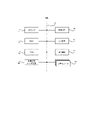
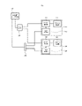
- FIG. 1 is a block diagram showing the hardware configuration of an optical coherence tomographic imaging apparatus according to a first embodiment
- FIG. 1 is a block diagram showing the configuration of an optical coherence tomographic imaging apparatus according to a first embodiment
- FIG. 11 is a block diagram showing the configuration of an optical coherence tomographic imaging apparatus according to a second embodiment
- FIG. 11 is a block diagram showing the configuration of an optical coherence tomographic imaging apparatus according to a third embodiment
- FIG. 11 is a block diagram showing the configuration of an optical coherence tomographic imaging apparatus according to a fourth embodiment
- FIG. 11 is a block diagram showing the configuration of an optical coherence tomographic imaging apparatus according to a fifth embodiment
- FIG. 11 is a block diagram showing the configuration of an optical coherence tomographic imaging apparatus according to a sixth embodiment
- FIG. 11 is a block diagram showing the configuration of an optical coherence tomographic imaging apparatus according to a seventh embodiment
- FIG. 12 is a block diagram showing the configuration of an optical coherence tomographic imaging apparatus according to an eighth embodiment
- FIG. 21 is a schematic diagram showing a configuration when the optical coherence tomographic imaging apparatus according to the ninth embodiment is applied to a contact fingerprint scanner
- FIG. 21 is a schematic diagram (Part 1) showing the configuration when the optical coherence tomographic imaging apparatus according to the ninth embodiment is applied to a non-contact fingerprint scanner
- FIG. 20 is a schematic diagram (part 2) showing the configuration when the optical coherence tomographic imaging apparatus according to the ninth embodiment is applied to a non-contact fingerprint scanner;
- FIG. 1 is a block diagram showing the hardware configuration of an optical coherence tomographic imaging apparatus according to the first embodiment.
- an optical coherence tomographic imaging apparatus 100 includes a processor 11, a RAM (Random Access Memory) 12, a ROM (Read Only Memory) 13, and a storage device 14. there is The optical coherence tomographic imaging apparatus 100 may further include an input device 15 and an output device 16 . Also, the optical coherence tomographic imaging apparatus 100 according to the first embodiment includes a wavelength swept laser light source 101 and a plurality of optical system units 20 .
- the above-described processor 11, RAM 12, ROM 13, storage device 14, input device 15, output device 16, wavelength swept laser light source 101, and a plurality of optical system units 20 are connected via data bus 17. may be connected.
- the processor 11 reads a computer program.
- processor 11 is configured to read a computer program stored in at least one of RAM 12, ROM 13 and storage device .
- the processor 11 may read a computer program stored in a computer-readable recording medium using a recording medium reader (not shown).
- the processor 11 may acquire (that is, read) a computer program from a device (not shown) arranged outside the optical coherence tomography apparatus 100 via a network interface.
- the processor 11 controls the RAM 12, the storage device 14, the input device 15 and the output device 16 by executing the read computer program.
- the processor 11 may be configured as, for example, a CPU (Central Processing Unit), GPU (Graphics Processing Unit), FPGA (Field-Programmable Gate Array), DSP (Demand-Side Platform), and ASIC (Application Specific Integrate).
- the processor 11 may be configured with one of these, or may be configured to use a plurality of them in parallel.
- the RAM 12 temporarily stores computer programs executed by the processor 11.
- the RAM 12 temporarily stores data temporarily used by the processor 11 while the processor 11 is executing the computer program.
- the RAM 12 may be, for example, a D-RAM (Dynamic RAM).
- the ROM 13 stores computer programs executed by the processor 11 .
- the ROM 13 may also store other fixed data.
- the ROM 13 may be, for example, a P-ROM (Programmable ROM).
- the storage device 14 stores data that the optical coherence tomographic imaging apparatus 100 stores for a long period of time.
- Storage device 14 may act as a temporary storage device for processor 11 .
- the storage device 14 may include, for example, at least one of a hard disk device, a magneto-optical disk device, an SSD (Solid State Drive), and a disk array device.
- the input device 15 is a device that receives input instructions from the user of the optical coherence tomographic imaging apparatus 100 .
- Input device 15 may include, for example, at least one of a keyboard, mouse, and touch panel.
- the input device 15 may be configured as a mobile terminal such as a smart phone or a tablet terminal.
- the output device 16 is a device that outputs information about the optical coherence tomographic imaging apparatus 100 to the outside.
- the output device 16 may be a display device (for example, display) capable of displaying information about the optical coherence tomography apparatus 10 .
- the output device 16 may be a device (for example, a speaker) capable of outputting information about the optical coherence tomographic imaging apparatus 10 by voice.
- the input device 15 may be configured as a mobile terminal such as a smart phone or a tablet terminal.
- the wavelength swept laser light source 101 is a light source capable of generating laser light whose wavelength is continuously changed.
- the optical coherence tomographic imaging apparatus 100 according to this embodiment is configured to be able to take a tomographic image of a measurement target using the coherence of laser light emitted from a wavelength-swept laser light source 101 .
- the optical system unit 20 is configured as a unit including a plurality of optical members.
- the optical system unit 20 guides the light emitted from the wavelength-swept laser light source 101 to the measurement target, and is configured to interfere light scattered by the measurement target to generate interference light.
- a more specific configuration of the optical system unit 20 will be described later.
- a plurality of optical system units 20 are provided for one wavelength swept laser light source 101 .
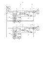
- FIG. 2 is a block diagram showing the configuration of the optical coherence tomographic imaging apparatus according to the first embodiment.
- an optical coherence tomographic imaging apparatus 100 is configured as an apparatus capable of imaging tomographic images of measurement objects 108 and 109 using light emitted from a wavelength-swept laser light source 101.
- the optical coherence tomographic imaging apparatus 100 branches one wavelength-swept laser light source 101 and outputs it to a plurality of units, and different measurement objects (here, measurement objects 108 and 109) in each unit. tomographic image can be captured.
- the optical pulse emitted from the wavelength-swept laser light source 101 is branched by the optical branching device 131, and then divided by the first optical interference/receiving unit 102, the optical beam scanning unit 104, and the signal processing unit 106. and a second unit including the optical interference/light receiving unit 103, the light beam scanning unit 105, and the signal processing unit 107, respectively.
- a tomographic image of the measurement object 108 is obtained in the first unit, and a tomographic image of the measurement object 109 is obtained in the second unit.
- the wavelength-swept laser light source 101 generates a light pulse whose wavelength increases from 1250 nm to 1350 nm for a duration of 10 ⁇ s, for example, and generates this light pulse at a repetition rate of 50 kHz every 20 ⁇ s.
- the light emitted from the wavelength-swept laser light source 101 and supplied to the light interference/light receiving unit 102 of the first unit via the light splitter 131 passes through the light beam scanning unit 104, is irradiated onto the measurement object 108, and is scattered. . Part of this scattered light is returned to the light interference/light receiving unit 102 and photoelectrically converted. An electrical signal output from the optical interference/light receiving unit 102 is converted into tomographic image data by the signal processing unit 106, and a tomographic image of the measurement object 108 is obtained.
- the light emitted from the wavelength swept laser light source 101 and supplied to the light interference/light receiving unit 103 of the second unit via the light splitter 131 passes through the light beam scanning unit 105, is irradiated onto the measurement object 109, and is scattered. be done. Part of this scattered light is returned to the light interference/light receiving unit 103 and photoelectrically converted. An electrical signal output from the optical interference/light receiving unit 103 is converted into tomographic image data by the signal processing unit 107, and a tomographic image of the measurement object 109 is obtained.
- the light supplied to the optical interference/light-receiving unit 102 of the first unit is input to the splitter/merger 112 via the circulator 111 .
- the light input to splitter/merger 112 is split into object light R11 and reference light R21.
- the object light R11 passes through a fiber collimator 115, an irradiation optical system 116 consisting of a scanning mirror and a lens, and irradiates an object 108 to be measured.
- the object light R31 scattered by the measurement object 108 returns to the splitter/merger 112 .
- the reference beam R21 passes through the reference beam mirror 113 and returns to the splitter/merger 112 .
- object light R31 scattered from measurement object 108 and reference light R41 reflected from reference light mirror 113 interfere with each other to generate interference light R51 and R61. That is, the intensity ratio between the interference light R51 and the interference light R61 is determined by the phase difference between the object light R31 and the reference light R41.
- the interference light R51 passes through the circulator 111, and the interference light R61 is directly input to the two-input balanced photodetector 114.
- a voltage corresponding to the intensity difference between the interference light R51 and the interference light R61 is output from the balanced photodetector 114 and input to the optical spectrum data generation/A-scan waveform generation section 117 forming the signal processing section 106 .
- the balanced photodetector 114 is a photodetector in which two photodiodes are connected in series and the connection serves as an output (differential output). Also, the band of the balanced photodetector 114 is 1 GHz or less.
- the optical spectrum data generation/A-scan waveform generation unit 117 generates an interference light spectrum based on the information on the wavelength change of the emitted light from the wavelength swept laser light source 101 and the information on the change in the intensity ratio between the interference lights R51 and R61. Generate data.
- the optical spectrum data generation/A-scan waveform generation unit 117 Fourier-transforms the generated interference light spectrum data to obtain data indicating the intensity of backscattered light (object light) at different positions in the depth direction (Z direction). (Hereinafter, the operation of obtaining data indicating the intensity of backscattered light (object light) in the depth direction (Z direction) at a certain position on the measurement object 108 is referred to as "A scan").
- an electrical signal with a repetition frequency of 50 kHz is supplied as a trigger signal from the wavelength-swept laser light source 101 to the signal processing unit 106 through the tomographic image generation unit 118 .
- the trigger signal is branched by the trigger signal splitter 132 after being output from the wavelength swept laser light source 101 and supplied to the tomographic image generator 118 and the tomographic image generator 128 .
- the intensity difference between the interference light R51 and the interference light R61 is given by the following equation (1).
- the interference light spectrum data I(k) obtained by measuring from wavenumber k 0 ⁇ k/2 to k 0 + ⁇ k/2 shows modulation with a period of 2 ⁇ /z 0 .
- the object to be measured is a mirror
- the object light irradiated to the object to be measured propagates to the inside while being attenuated to some extent and is sequentially backscattered, and the light scattering points of the object light are distributed in a range from the surface to a certain depth.
- the interference light spectrum has a modulation period of 2 ⁇ /(z 0 ⁇ z) to 2 ⁇ /(z 0 + ⁇ z). appear overlapping.
- the irradiation position of the object light R31 is scanned on the measurement object 108 by the irradiation optical system 116 .
- the beam position setting unit 119 controls the irradiation optical system 116 according to the trigger signal supplied through the tomographic image generation unit 118 to move the irradiation position of the object light R31 in the scanning line direction (X direction).
- a two-dimensional map of the intensity of the backscattered light (object light) in the scanning line direction and the depth direction is generated as tomographic structure data.
- B-scan the operation of repeatedly performing the A-scan operation in the scanning line direction (X direction) and connecting the measurement results.
- the irradiation optical system 116 moves the irradiation position of the object light R31 not only in the direction of the scanning line but also in the direction perpendicular to the scanning line (Y direction) while repeatedly performing the B-scanning operation. By connecting the measurement results, three-dimensional tomographic structure data can be obtained. scan”).
- the tomographic structure data of the object 109 to be measured can be obtained by the same procedure (that is, the same procedure as in the first unit described above).
- the optical coherence tomographic imaging apparatus 100 As described with reference to FIGS. 1 and 2, in the optical coherence tomographic imaging apparatus 100 according to the first embodiment, light emitted from one wavelength-swept laser light source 101 is distributed to a plurality of units for measurement. will be In this way, it is possible to acquire the tomographic structure data of the object to be measured in each unit while sharing the high-cost wavelength swept laser light source among a plurality of units. As a result, it becomes possible to suppress the device cost.
- ⁇ Second embodiment> An optical coherence tomographic imaging apparatus 200 according to the second embodiment will be described with reference to FIG.
- the second embodiment may differ from the above-described first embodiment only in a part of configuration and operation, and the other parts may be the same as those of the first embodiment. For this reason, in the following, portions different from the already described first embodiment will be described in detail, and descriptions of overlapping portions will be omitted as appropriate.
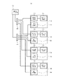
- FIG. 3 is a block diagram showing the configuration of an optical coherence tomographic imaging apparatus according to the second embodiment. Note that FIG. 3 omits illustration of detailed components included in the light interference/light receiving unit, the light beam scanning unit, and the signal processing unit shown in FIG. 2 .
- an optical coherence tomographic imaging apparatus 200 includes four units 210, 220, 230, and 240 as input destinations of light emitted from a wavelength-swept laser light source 201. ing.
- the number of units into which a plurality of branched lights are input is not particularly limited.
- the number of units may be, for example, 5, 6 or more.
- the light emitted from the wavelength-swept laser light source 201 is split into four lights by the light splitter 202 . Then, each branched light is transmitted to the optical interference/light receiving section 211 of the first unit 210, the optical interference/light receiving section 221 of the second unit 220, the optical interference/light receiving section 231 of the third unit 230, and It is supplied to the optical interference/light receiving section 241 of the fourth unit 240 .
- the light input to the light interference/light receiving section 211 of the first unit 210 is used for scanning by the light beam scanning section 212 .
- the light input to the optical interference/light receiving section 221 of the second unit 220 is used for scanning by the light beam scanning section 222 .
- the light input to the light interference/light receiving section 231 of the third unit 230 is used for scanning by the light beam scanning section 232 .
- the light input to the light interference/light receiving section 241 of the fourth unit 240 is used for scanning by the light beam scanning section 242 .
- each unit can acquire tomographic structure data of mutually different measurement objects (here, four measurement objects).
- the trigger signal output from the wavelength swept laser light source 201 is also split by the trigger signal splitter 203, and the signal processing section 213 of the unit 210, the signal processing section 223 of the unit 220, the signal processing section 233 of the unit 230, and the It is supplied to the signal processing section 243 of the unit 240 .
- the optical coherence tomographic imaging apparatus 200 As described with reference to FIG. 3, in the optical coherence tomographic imaging apparatus 200 according to the second embodiment, light emitted from one wavelength-swept laser light source 101 is distributed to a larger number of units than in the first embodiment. measurements are taken. In this way, the high-cost wavelength swept laser light source can be shared by a larger number of units, so that the device cost can be further reduced.
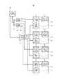
- FIG. 4 is a block diagram showing the configuration of an optical coherence tomographic imaging apparatus according to the third embodiment.
- the same symbols are assigned to the same components as those shown in FIG.
- an optical coherence tomographic imaging apparatus 300 includes an optical amplifier 204 that amplifies light pulses emitted from a wavelength-swept laser light source 201.
- the optical pulse emitted from the wavelength swept laser light source 201 is first amplified by the optical amplifier 204 .
- the amplified light is split into two by the optical splitter 205 .
- Each light branched by the optical splitter 205 is supplied to the optical interference/light receiving section 211 of the first unit 210 and the optical interference/light receiving section 221 of the second unit 220 .
- the light pulse emitted from the wavelength swept laser light source 201 is amplified before being split.
- the reduction in optical pulse power due to branching can be compensated for by amplification. Therefore, for example, even if the number of branches is large and the power of the optical pulse after branching is insufficient as it is, the power is compensated for by amplification, and a tomographic image can be captured appropriately.
- FIG. 5 is a block diagram showing the configuration of an optical coherence tomographic imaging apparatus according to the fourth embodiment.
- the same symbols are attached to the same components as those shown in FIGS.
- an optical coherence tomographic imaging apparatus 400 includes a first optical branching device 206 that branches an optical pulse emitted from a wavelength-swept laser light source 201, and a first optical branching device. It has two optical amplifiers 207 that amplify each of the amplified lights, and a second optical splitter 208 that further splits each of the lights amplified by each of the optical amplifiers 207 .
- the light pulse emitted from the wavelength-swept laser light source 201 is first split into two lights by the first optical splitter 206 .
- the two split lights are supplied to two optical amplifiers 207, respectively.
- the optical amplifier 207 amplifies each of the two lights split by the first optical splitter 206 .
- the two lights amplified by the optical amplifier 207 are supplied to the second optical splitter 208, respectively.
- the second optical splitter 208 splits the input light into two.
- the optical pulse emitted from the wavelength swept laser light source 201 passes through the first optical splitter 206, the optical amplifier 207, and the second optical splitter 208 and is split into four lights.
- the four lights emitted from the second optical splitter 208 are the optical interference/light receiving section 211 of the first unit 210, the optical interference/light receiving section 221 of the second unit 220, the It is supplied to the optical interference/light receiving section 231 of the third unit 230 and the optical interference/light receiving section 241 of the fourth unit 240 .
- optical pulses are branched in stages with amplification interposed therebetween. In this way, when optical pulses are branched into a relatively large number, branching and amplification can be performed appropriately.
- the optical pulse is branched in two steps, but the optical pulse may be branched in three or more steps. In that case, amplification may be performed before branching at each stage (that is, amplification may be performed multiple times in stages).
- ⁇ Fifth Embodiment> An optical coherence tomographic imaging apparatus 500 according to the fifth embodiment will be described with reference to FIG. It should be noted that the fifth embodiment may differ from the first to fourth embodiments described above only in a part of the configuration and operation, and the other parts may be the same as those of the first to fourth embodiments. Therefore, in the following, portions different from the respective embodiments already described will be described in detail, and descriptions of other overlapping portions will be omitted as appropriate.
- FIG. 6 is a block diagram showing the configuration of an optical coherence tomographic imaging apparatus according to the fifth embodiment.
- the same reference numerals are assigned to the same components as those shown in FIGS.
- an optical coherence tomographic imaging apparatus 500 is configured with an optical switch 209 as an element for branching the light pulse emitted from the wavelength swept laser light source 201.
- the optical switch 209 is configured to be able to time-divisionally split the wavelength-swept laser light source 201 (that is, switch the optical path depending on the timing).
- the optical switch 209 switches so that the light pulses emitted from the wavelength swept laser light source 201 are sequentially supplied to the units 210 and 220.
- the optical switch 209 is switched so that the optical pulse is first supplied to the optical interference/light receiving section 211 of the first unit 210 .
- the optical switch 209 is switched so that the optical pulse is supplied to the optical interference/light receiving section 221 of the second unit 220 .
- the optical pulse emitted from the wavelength swept laser light source 201 is split by the optical switch 209 .
- the optical switch 209 it is possible to suppress a decrease in the power of the optical pulse due to branching. Therefore, it is possible to maintain the power of the optical pulse after branching without providing an optical amplifier as in the above-described third and fourth embodiments.
- FIG. 7 is a block diagram showing the configuration of an optical coherence tomographic imaging apparatus according to the sixth embodiment.
- an optical coherence tomographic imaging apparatus 600 is configured as one integrated unit 310 in which the optical interference/light receiving units and signal processing units in a plurality of units are common.
- the aggregation unit 310 includes optical interference/light receiving units 311 and 321 and signal processing units 313 and 323 .
- the optical pulses branched by the optical branching unit 302 are supplied to each of the optical interference/light receiving units 311 and 321 included in the aggregation unit 310 . Further, the signal processing units 313 and 323 included in the aggregation unit 310 are supplied with the trigger signal split by the trigger signal splitter 303 .
- a plurality of light beam scanners 312 and 322 are remotely located in the aggregation unit 310 .
- Each of the plurality of light beam scanning units 312 and 322 is configured to operate via different optical interference/light receiving units and signal processing units included in the aggregation unit 310 .
- Each of the light beam scanning units 312 and 322 is capable of scanning a plurality of different objects to be measured.
- a plurality of optical interference/light receiving units and signal processing units are configured as one integrated unit 310 in common.
- the device configuration can be simplified, and the cost is reduced. It is also possible to suppress the increase in
- FIG. 8 is a block diagram showing the configuration of an optical coherence tomographic imaging apparatus according to the seventh embodiment.
- an optical coherence tomographic imaging apparatus 700 includes an optical combiner 721 and an optical splitter 722 .
- the optical combiner 721 is configured to combine the wavelength-swept first optical pulse and the second optical pulse to output.
- the optical splitter 722 is configured to split and output the light combined by the optical combiner 721 .
- a wavelength-swept first optical pulse and a second optical pulse synchronized with repetition of this optical pulse are emitted from a wavelength-swept laser light source 701 .
- a first wavelength-swept optical pulse is generated with a 50 kHz repetition every 20 ⁇ s, increasing in wavelength from 1250 nm to 1350 nm for a duration of 10 ⁇ s.
- the second optical pulse is generated with a wavelength band of 1550 nm and a repetition rate of 50 kHz.
- the first optical pulse and the second optical pulse are combined at the optical combiner 721 and split at the optical splitter 723 .
- the optical combiner 721 can suppress optical loss during combining using a wavelength combiner.
- the light branched by the optical splitter 723 is sent to the first unit consisting of the light interference/light receiving unit 702, the light beam scanning unit 104, and the signal processing unit 106, the light interference/light receiving unit 703, the light beam scanning unit 105, It is fed to a second unit consisting of signal processing section 107 .
- the light emitted from the wavelength swept laser light source 701 and supplied to the optical interference/light receiving section 702 via the optical combiner 721 and optical splitter 722 is input to the trigger signal separation section 724 .
- the first light pulse is guided to the circulator 111, and the second light pulse is photoelectrically converted by the light receiver.
- the first light pulse is used to acquire tomographic structure data of the measurement object 108 in the same procedure as in the first embodiment (see FIG. 2).
- An electrical signal obtained by photoelectrically converting the second light pulse is input to the tomographic image generation unit 118 of the signal processing unit 106 as in the first embodiment.
- the tomographic structure data of the object 109 to be measured can be obtained by the same procedure (that is, the same procedure as in the first unit described above).
- the first pulse and the second pulse are generated in each unit (specifically, the trigger signal separator 724 and 725).
- the trigger signal separator 724 and 725 it is not necessary to separately supply the light pulses for generating the object light and the reference light and the light pulses for the trigger signal to each unit. Therefore, it is not necessary to separately provide an optical splitter and a trigger signal splitter, for example, in front of each unit.
- FIG. 8 An optical coherence tomographic imaging apparatus 800 according to the eighth embodiment will be described with reference to FIG. It should be noted that the eighth embodiment may differ from the first to seventh embodiments described above only in part of the operation, and may be the same as the first to seventh embodiments in other respects. Therefore, in the following, portions different from the respective embodiments already described will be described in detail, and descriptions of other overlapping portions will be omitted as appropriate.
- FIG. 9 is a block diagram showing the configuration of an optical coherence tomographic imaging apparatus according to the eighth embodiment.
- each unit of the optical coherence tomographic imaging apparatus 800 includes trigger signal extractors 822 and 823 .
- the trigger signal extraction units 822 and 823 are configured to be capable of generating an electrical signal synchronized with the optical pulse by branching and photoelectrically converting a portion of the power of the optical pulse.
- a light pulse is emitted from the wavelength-swept laser light source 801, and a first unit consisting of a light interference/light receiving unit 802, a light beam scanning unit 104, a signal processing unit 106, and , the light interference/light receiving unit 803 , the light beam scanning unit 105 and the signal processing unit 107 .
- one of the lights split by the optical splitter 821 is supplied to the optical interference/light receiving section 802 .
- the optical pulse supplied to the optical interference/light receiving unit 802 is input to the trigger signal extraction unit 822 .
- the trigger signal extractor 822 splits a portion of the power of the optical pulse and photoelectrically converts it to generate an electrical signal synchronized with the optical pulse. Most of the remaining power of the optical pulse is used to acquire tomographic structure data of the measurement object 108 in the same procedure as in the first embodiment (see FIG. 2).
- the electrical signal obtained by the trigger signal extraction unit 822 is input to the tomographic image generation unit 118 of the signal processing unit 106 as a trigger signal.
- the tomographic structure data of the object 109 to be measured can be obtained by the same procedure (that is, the same procedure as in the first unit described above).
- each unit specifically, the trigger signal extraction units 822 and 823 of each unit.
- FIG. 10 to 12 An optical coherence tomographic imaging apparatus according to the ninth embodiment will be described with reference to FIGS. 10 to 12.
- FIG. The ninth embodiment describes specific application examples of the optical coherence tomographic imaging apparatuses according to the above-described first to eighth embodiments, and the basic configuration and operation of the apparatus are described in the first to eighth embodiments. It may be the same as the eighth embodiment. Therefore, in the following, portions different from the respective embodiments already described will be described in detail, and descriptions of other overlapping portions will be omitted as appropriate.
- FIG. 10 is a schematic diagram showing the configuration when the optical coherence tomographic imaging apparatus according to the ninth embodiment is applied to a contact fingerprint scanner.
- symbol is attached
- the optical coherence tomography apparatus may be applied to a contact fingerprint scanner (that is, a device that reads fingerprints by touching a finger to the device).
- the scanning unit 910 with which the living finger 50 comes into contact may be configured with the irradiation optical system 116 .
- the irradiation optical system 116 irradiates the finger 50 of the living body in contact with the scanning unit 910 with a light beam. Scattered light scattered by finger 50 of the living body enters irradiation optical system 116 . Based on this scattered light, a fingerprint image is generated in a contact fingerprint scanner.
- the irradiation optical system 116 is supplied with the laser light emitted from the wavelength-swept laser light source 101 in a branched state. Therefore, although illustration is omitted here, a plurality of scanning units 910 may be provided for one wavelength swept laser light source 101 .
- FIG. 11 is a schematic diagram (Part 1) showing the configuration when the optical coherence tomographic imaging apparatus according to the ninth embodiment is applied to a non-contact fingerprint scanner.
- FIG. 12 is a schematic diagram (part 2) showing the configuration when the optical coherence tomographic imaging apparatus according to the ninth embodiment is applied to a non-contact fingerprint scanner.
- FIGS. 11 and 12 the same symbols are attached to the same elements as those shown in FIG.
- the optical coherence tomography apparatus may be applied to a non-contact fingerprint scanner (that is, a device that reads fingerprints without touching the finger to the device).
- the scanning unit 920 over which the living finger 50 is held may be configured with the irradiation optical system 116 .
- the irradiation optical system 116 irradiates a light beam to the living finger 50 that is not in contact with the scanning unit 920 .
- Scattered light scattered by finger 50 of the living body enters irradiation optical system 116 . Based on this scattered light, a fingerprint image is generated in a contactless fingerprint scanner.
- the optical coherence tomography apparatus may be applied to a non-contact fingerprint scanner with a guide.
- the scanning unit 930 over which the finger 50 of the living organism is held is provided with guide units 931 and 932 on which the finger 50 of the living organism is placed. In this way, even if the finger 50 of the living body is brought into contact with the guide parts 931 and 932, the scanner part 930 and the finger 50 of the living body do not contact each other (that is, the non-contact state can be maintained).
- the irradiation optical system 116 in the non-contact scanner is also supplied with the laser light emitted from the wavelength swept laser light source 101 in a branched state. Therefore, although illustration is omitted here, a plurality of scanning units 920 or 930 may be provided for one wavelength swept laser light source 101 .
- the optical coherence tomographic imaging apparatus is applied to contact fingerprint scanners or non-contact fingerprint scanners.
- the high-cost wavelength swept laser light source 101 is shared by a plurality of units, each unit can obtain a fingerprint image of the living finger 50 . Therefore, even if there is only one wavelength swept laser light source 101, for example, fingerprint images of a plurality of living bodies can be obtained at the same time.
- a processing method of recording a program for operating the configuration of each embodiment so as to realize the functions of each embodiment described above on a recording medium, reading the program recorded on the recording medium as a code, and executing it on a computer is also implemented. Included in the category of form. That is, a computer-readable recording medium is also included in the scope of each embodiment. In addition to the recording medium on which the above program is recorded, the program itself is also included in each embodiment.
- a floppy (registered trademark) disk, hard disk, optical disk, magneto-optical disk, CD-ROM, magnetic tape, non-volatile memory card, and ROM can be used as recording media.
- the program recorded on the recording medium alone executes the process, but also the one that operates on the OS and executes the process in cooperation with other software and functions of the expansion board. included in the category of
- the optical coherence tomographic imaging apparatus includes a wavelength-swept laser light source, a branching section that branches light emitted from the wavelength-swept laser light source into a plurality of lights, and a plurality of lights output from the branching section. and a plurality of units for acquiring tomographic structure information for different measurement objects using each of the plurality of units, each of the plurality of units branching the light output from the branching unit into object light and reference light.
- a branch generating unit that generates a branch, a light beam scanning unit that irradiates the object light onto the measurement object, and the object light scattered by the measurement object and the reference light according to the intensity of the interference light that interferes an optical coherence tomographic imaging apparatus comprising: a signal generation unit that generates an electric signal by using a signal; and an information generation unit that generates tomographic structure information of the object to be measured based on the electric signal.
- the branching unit branches light emitted from the wavelength-swept laser light source, amplifies the branched light, further branches the amplified light, and divides the plurality of lights. It is an optical coherence tomographic imaging apparatus according to Supplementary Note 1, which outputs as .
- (Appendix 4) 4. The optical coherence tomographic imaging apparatus according to any one of appendices 1 to 3, wherein the branching unit time-divides the light emitted from the wavelength-swept laser light source and outputs the light as the plurality of lights. It is an optical coherence tomographic imaging apparatus of description.
- the wavelength-swept laser light source emits a first optical pulse and a second optical pulse
- the branching unit emits the first optical pulse and the second optical pulse.
- the light pulses are combined and output as the plurality of lights, and each of the plurality of units divides the light output from the branching section into the first light pulse and the second light
- the first optical pulse is output as light for generating the object light and the reference light
- the second optical pulse is used as a trigger for the signal generator to generate the tomographic structure information.
- each of the plurality of units separates and photoelectrically converts a portion of the power of the light output from the branching unit, so that the signal generating unit is the tomographic structure.
- a computer emits light from a wavelength-swept laser light source, branches the light emitted from the wavelength-swept laser light source into a plurality of lights, and divides each of the plurality of lights into an optical coherence tomography method for acquiring tomographic structure information for different measurement objects in each of a plurality of units, wherein each of the plurality of units further splits the plurality of lights into object light and reference and irradiating the object light onto the object to be measured, and generating an electric signal according to the intensity of the interference light resulting from interference between the object light scattered by the object to be measured and the reference light. and an optical coherence tomographic imaging method for generating tomographic structural information of the object to be measured based on the electrical signal.
- the recording medium according to appendix 9 emits light from a wavelength-swept laser light source to a computer, branches the light emitted from the wavelength-swept laser light source into a plurality of lights, and uses each of the plurality of lights to An optical coherence tomography method for obtaining tomographic structure information for different measurement objects in each of a plurality of units, wherein each of the plurality of units further splits the plurality of lights into object light and reference light.
- the recording medium stores a computer program for executing an optical coherence tomographic imaging method for generating tomographic structure information of the object to be measured based on the signal.
- Appendix 10 causes a computer to emit light from a wavelength-swept laser light source, split the light emitted from the wavelength-swept laser light source into a plurality of lights, and use each of the plurality of lights to An optical coherence tomography method for obtaining tomographic structure information for different measurement objects in each of a plurality of units, wherein each of the plurality of units further splits the plurality of lights into object light and reference light.
- a computer program for executing an optical coherence tomography method for generating tomographic structure information of the measurement object based on a signal.
- optical coherence tomographic imaging apparatus 101 wavelength sweeping laser light source 102 optical interference/light receiving unit 104 light beam scanning unit 108 measurement object 111 circulator 112 branching/combining unit 113 reference light mirror 115 fiber collimator 116 irradiation optical system 117 optical spectrum data generation A Scan waveform generation unit 118 Tomographic image generation unit 119 Beam position setting unit 131 Optical splitter 132 Trigger signal splitter 204 Optical amplifier 205 Optical splitter 206 First optical splitter 207 Optical amplifier 208 Second optical splitter 209 Optical switch 310 Aggregation Unit 721 Optical Combiner 722 Optical Splitter 724 Trigger Signal Separating Section 822 Trigger Signal Extracting Section 910, 920, 930 Scanning Section 931, 932 Guide Section
Landscapes
- Health & Medical Sciences (AREA)
- General Health & Medical Sciences (AREA)
- Physics & Mathematics (AREA)
- General Physics & Mathematics (AREA)
- Nuclear Medicine, Radiotherapy & Molecular Imaging (AREA)
- Radiology & Medical Imaging (AREA)
- Life Sciences & Earth Sciences (AREA)
- Chemical & Material Sciences (AREA)
- Analytical Chemistry (AREA)
- Biochemistry (AREA)
- Immunology (AREA)
- Pathology (AREA)
- Investigating Or Analysing Materials By Optical Means (AREA)
Priority Applications (3)
| Application Number | Priority Date | Filing Date | Title |
|---|---|---|---|
| PCT/JP2021/024337 WO2023275929A1 (ja) | 2021-06-28 | 2021-06-28 | 光干渉断層撮像装置、光干渉断層撮像方法、及び記録媒体 |
| JP2023531146A JP7666598B2 (ja) | 2021-06-28 | 2021-06-28 | 光干渉断層撮像装置、光干渉断層撮像方法、及び記録媒体 |
| US18/571,402 US20240288263A1 (en) | 2021-06-28 | 2021-06-28 | Optical coherence tomography imaging apparatus, optical coherence tomography imaging method, and recording medium |
Applications Claiming Priority (1)
| Application Number | Priority Date | Filing Date | Title |
|---|---|---|---|
| PCT/JP2021/024337 WO2023275929A1 (ja) | 2021-06-28 | 2021-06-28 | 光干渉断層撮像装置、光干渉断層撮像方法、及び記録媒体 |
Publications (1)
| Publication Number | Publication Date |
|---|---|
| WO2023275929A1 true WO2023275929A1 (ja) | 2023-01-05 |
Family
ID=84691001
Family Applications (1)
| Application Number | Title | Priority Date | Filing Date |
|---|---|---|---|
| PCT/JP2021/024337 Ceased WO2023275929A1 (ja) | 2021-06-28 | 2021-06-28 | 光干渉断層撮像装置、光干渉断層撮像方法、及び記録媒体 |
Country Status (3)
| Country | Link |
|---|---|
| US (1) | US20240288263A1 (https=) |
| JP (1) | JP7666598B2 (https=) |
| WO (1) | WO2023275929A1 (https=) |
Citations (8)
| Publication number | Priority date | Publication date | Assignee | Title |
|---|---|---|---|---|
| JP2002014037A (ja) * | 2000-04-26 | 2002-01-18 | Fuji Photo Film Co Ltd | 光断層画像化装置 |
| WO2008090599A1 (ja) * | 2007-01-22 | 2008-07-31 | School Juridical Person Kitasato Institute | オプティカル・コヒーレンス・トモグラフィー装置 |
| JP2010540914A (ja) * | 2007-09-28 | 2010-12-24 | カール ツァイス メディテック アクチエンゲゼルシャフト | ショート・コヒーレンス干渉計 |
| WO2013118541A1 (ja) * | 2012-02-08 | 2013-08-15 | 株式会社 日立ハイテクノロジーズ | 光断層画像測定装置 |
| JP2014525563A (ja) * | 2011-08-19 | 2014-09-29 | マイケルソン ダイアグノステックス リミテッド | 干渉計用検出回路 |
| JP2018521326A (ja) * | 2015-07-22 | 2018-08-02 | メドルミクス, エセ.エレ.Medlumics, S.L. | 抑制された多重散乱クロストークを有する複数の干渉計を用いる高速光干渉断層撮影 |
| JP2020060455A (ja) * | 2018-10-10 | 2020-04-16 | 株式会社吉田製作所 | 光干渉断層画像生成装置 |
| JP2021503595A (ja) * | 2017-11-16 | 2021-02-12 | クオリティー ヴィジョン インターナショナル インコーポレイテッドQuality Vision International, Inc. | 測定機のための複数ビーム走査システム |
Family Cites Families (2)
| Publication number | Priority date | Publication date | Assignee | Title |
|---|---|---|---|---|
| JPH03123323A (ja) * | 1989-10-06 | 1991-05-27 | Furukawa Electric Co Ltd:The | ファイバカップラー |
| JP2002050816A (ja) | 2000-08-02 | 2002-02-15 | Fujitsu Ltd | 光増幅器 |
-
2021
- 2021-06-28 WO PCT/JP2021/024337 patent/WO2023275929A1/ja not_active Ceased
- 2021-06-28 US US18/571,402 patent/US20240288263A1/en active Pending
- 2021-06-28 JP JP2023531146A patent/JP7666598B2/ja active Active
Patent Citations (8)
| Publication number | Priority date | Publication date | Assignee | Title |
|---|---|---|---|---|
| JP2002014037A (ja) * | 2000-04-26 | 2002-01-18 | Fuji Photo Film Co Ltd | 光断層画像化装置 |
| WO2008090599A1 (ja) * | 2007-01-22 | 2008-07-31 | School Juridical Person Kitasato Institute | オプティカル・コヒーレンス・トモグラフィー装置 |
| JP2010540914A (ja) * | 2007-09-28 | 2010-12-24 | カール ツァイス メディテック アクチエンゲゼルシャフト | ショート・コヒーレンス干渉計 |
| JP2014525563A (ja) * | 2011-08-19 | 2014-09-29 | マイケルソン ダイアグノステックス リミテッド | 干渉計用検出回路 |
| WO2013118541A1 (ja) * | 2012-02-08 | 2013-08-15 | 株式会社 日立ハイテクノロジーズ | 光断層画像測定装置 |
| JP2018521326A (ja) * | 2015-07-22 | 2018-08-02 | メドルミクス, エセ.エレ.Medlumics, S.L. | 抑制された多重散乱クロストークを有する複数の干渉計を用いる高速光干渉断層撮影 |
| JP2021503595A (ja) * | 2017-11-16 | 2021-02-12 | クオリティー ヴィジョン インターナショナル インコーポレイテッドQuality Vision International, Inc. | 測定機のための複数ビーム走査システム |
| JP2020060455A (ja) * | 2018-10-10 | 2020-04-16 | 株式会社吉田製作所 | 光干渉断層画像生成装置 |
Also Published As
| Publication number | Publication date |
|---|---|
| JP7666598B2 (ja) | 2025-04-22 |
| US20240288263A1 (en) | 2024-08-29 |
| JPWO2023275929A1 (https=) | 2023-01-05 |
Similar Documents
| Publication | Publication Date | Title |
|---|---|---|
| US9833148B2 (en) | Methods and systems for integrated imaging using optical coherence tomography and photoacoustic imaging | |
| US7812961B2 (en) | Method, apparatus, and program for processing tomographic images | |
| JP2021512336A (ja) | コヒーレンスゲーテッド光音響リモートセンシング(cg−pars) | |
| EP4306901B1 (en) | Method for multiple reference arm spectral domain optical coherence tomography | |
| JP5373485B2 (ja) | Oct装置及びその干渉信号レベル制御方法 | |
| CN105476605A (zh) | 高速光学相干层析成像系统和方法 | |
| WO2016023502A1 (en) | Phase-inverted sidelobe-annihilated optical coherence tomography | |
| CN110907451A (zh) | 一种基于艾里光束和组织透明化技术的超深oct系统装置 | |
| JP2005351839A (ja) | 断層映像装置 | |
| JP7327620B2 (ja) | 光干渉断層撮像装置、撮像方法、及び、撮像プログラム | |
| EP2799838A1 (en) | Information signal generating method | |
| JP7201007B2 (ja) | 光干渉断層撮像装置、および光干渉断層画像の生成方法 | |
| JP7666598B2 (ja) | 光干渉断層撮像装置、光干渉断層撮像方法、及び記録媒体 | |
| US20230102868A1 (en) | Optical coherence tomography (oct) apparatus and method for controlling an opticalcoherence tomography apparatus | |
| CN205597893U (zh) | 高速光学相干层析成像系统 | |
| KR20130126151A (ko) | 빗살무늬 스펙트럼의 광원을 이용한 광 간섭성 단층 촬영 장치 | |
| JP6404451B2 (ja) | 光音響計測装置及びプローブ | |
| JP5631671B2 (ja) | 光イメージング装置 | |
| JP7540492B2 (ja) | 光干渉断層撮像装置 | |
| EP4129156A1 (en) | Optical coherence tomography device, imaging method, and non-transitory computer-readable medium in which imaging program is stored | |
| WO2022044204A1 (ja) | 光干渉断層撮像装置 | |
| JP2012110521A (ja) | Octシステム | |
| JP2017211192A (ja) | 撮像装置及び撮像装置の制御方法 | |
| CN116849620A (zh) | 一种皮肤诊断装置 | |
| JP2010025943A (ja) | 断層映像装置 |
Legal Events
| Date | Code | Title | Description |
|---|---|---|---|
| 121 | Ep: the epo has been informed by wipo that ep was designated in this application |
Ref document number: 21948243 Country of ref document: EP Kind code of ref document: A1 |
|
| WWE | Wipo information: entry into national phase |
Ref document number: 2023531146 Country of ref document: JP |
|
| WWE | Wipo information: entry into national phase |
Ref document number: 18571402 Country of ref document: US |
|
| NENP | Non-entry into the national phase |
Ref country code: DE |
|
| 122 | Ep: pct application non-entry in european phase |
Ref document number: 21948243 Country of ref document: EP Kind code of ref document: A1 |