WO2023248792A1 - 植物育成装置および植物育成方法 - Google Patents
植物育成装置および植物育成方法 Download PDFInfo
- Publication number
- WO2023248792A1 WO2023248792A1 PCT/JP2023/021119 JP2023021119W WO2023248792A1 WO 2023248792 A1 WO2023248792 A1 WO 2023248792A1 JP 2023021119 W JP2023021119 W JP 2023021119W WO 2023248792 A1 WO2023248792 A1 WO 2023248792A1
- Authority
- WO
- WIPO (PCT)
- Prior art keywords
- plant
- artificial light
- light
- light source
- plant growing
- Prior art date
- Legal status (The legal status is an assumption and is not a legal conclusion. Google has not performed a legal analysis and makes no representation as to the accuracy of the status listed.)
- Ceased
Links
Images





Classifications
-
- A—HUMAN NECESSITIES
- A01—AGRICULTURE; FORESTRY; ANIMAL HUSBANDRY; HUNTING; TRAPPING; FISHING
- A01G—HORTICULTURE; CULTIVATION OF VEGETABLES, FLOWERS, RICE, FRUIT, VINES, HOPS OR SEAWEED; FORESTRY; WATERING
- A01G31/00—Soilless cultivation, e.g. hydroponics
- A01G31/02—Special apparatus therefor
-
- A—HUMAN NECESSITIES
- A01—AGRICULTURE; FORESTRY; ANIMAL HUSBANDRY; HUNTING; TRAPPING; FISHING
- A01G—HORTICULTURE; CULTIVATION OF VEGETABLES, FLOWERS, RICE, FRUIT, VINES, HOPS OR SEAWEED; FORESTRY; WATERING
- A01G7/00—Botany in general
Definitions
- the present invention relates to a plant growing device and a plant growing method for growing plants using artificial light.
- BACKGROUND ART Greenhouse horticulture and plant factories are being considered as measures to increase production and achieve stable harvests of agricultural crops. Furthermore, in plant factories, consideration is being given to the adoption of vertical farming, which allows stable production of agricultural products in a relatively small space, even if it is not possible to secure vast amounts of land as in conventional agriculture.
- the intensity of light irradiated onto crops from an artificial light source for photosynthesis, environmental conditions such as temperature, humidity, carbon dioxide (CO 2 ) concentration, and wind speed in the plant growing space, and fertilizer components for plant growth are important. It is possible to control each parameter such as. Therefore, it is possible to produce crops year-round, and it is possible to dramatically increase the productivity of crops.
- Patent Document 1 discloses a closed plant factory that cultivates plants by irradiating artificial light such as LED light without using sunlight.
- this closed plant factory by irradiating light closely from the sides of the plants, it is possible to grow vegetables that grow vertically and grow taller, such as tomatoes and cucumbers.
- an object of the present invention is to provide a plant growing device and a plant growing method that can further improve the productivity of plants per unit space while suppressing costs.
- one aspect of the plant growing device is a plant growing device that grows plants using artificial light, the artificial light being irradiated from the side with respect to the growth direction of the plant. and an elongation regulating part having a pair of elongation regulating surfaces that are arranged opposite to each other across the plant in the irradiation direction of the artificial light and that regulates the lateral extension of the plant.
- the artificial light sources may be arranged opposite to each other with the plant in between, and may irradiate the artificial light from both sides with respect to the growth direction of the plant.
- the plants can be irradiated with light more efficiently.
- the separation width between the pair of elongation regulating surfaces is such that the cumulative leaf area of all the leaves of the plant existing between the pair of elongation regulating surfaces is calculated per unit area of the elongation regulating surfaces.
- the distance may be such that the index value converted to is less than 4. In this case, the artificial light irradiated onto the plants can be effectively utilized without wasting it.
- the separation width between the pair of elongation regulating surfaces may be set to be greater than or equal to the size of a crop harvested from the plant.
- the crops can be cultivated without being destroyed.
- the elongation regulating section may form a closed space surrounding the plant.
- the width (thickness), height, and depth of the space occupied by the plants can be appropriately defined.
- the width of the space occupied by one plant defined by the elongation regulating section in the irradiation direction of the artificial light is narrower than the depth of the space occupied by one plant. Good too. In this case, it is possible to restrict the expansion of the expansion regulating portion in the width direction and prevent the expansion in the depth direction from being obstructed, so that the plant can be grown appropriately.
- the size of the elongation regulating surface is equivalent to the size of the light emitting surface of the artificial light source, and even if the entire surface of the elongation regulating surface is the irradiation surface of the artificial light. good. In this case, light can be appropriately irradiated into the space occupied by the plant defined by the extension regulating section.
- the photosynthetic photon flux density (PPFD) of the artificial light emitted from the artificial light source may be 400 ⁇ mol ⁇ m ⁇ 2 ⁇ s ⁇ 1 or more.
- the photosynthetic efficiency of soybeans can be maximized, and productivity can be further improved.
- the photosynthetic photon flux density (PPFD) of the artificial light emitted from the artificial light source may be 2000 ⁇ mol ⁇ m ⁇ 2 ⁇ s ⁇ 1 or less.
- the photosynthetic photon flux density (PPFD) of the artificial light emitted from the artificial light source may be 1000 ⁇ mol ⁇ m ⁇ 2 ⁇ s ⁇ 1 or less.
- the production rate (growth rate) of plants can be increased while suppressing the decrease in photosynthetic efficiency to an acceptable range.
- the elongation regulating surface is arranged between the plant and the artificial light source, and is a light-transmissive member that can transmit the artificial light, or a light-transmitting member that can transmit the artificial light. It may be made of a light-transmissive member.
- the plant can be appropriately irradiated with light emitted from the artificial light source via the extension regulating section. Furthermore, since it is possible to avoid plants from coming into contact with artificial light sources, it is possible to suppress problems caused to plants due to heat from the artificial light sources.
- the artificial light source may be provided on the surface of the elongation regulating surface.
- the extension regulating section can also be used as a support for supporting the artificial light source, so the number of parts can be reduced and the device can be made more compact.
- the elongation regulating surface may be a flat or corrugated plate-like body, and the artificial light source may be provided on the surface of the plate-like body.
- the artificial light source can be appropriately supported by the extension regulating section, and the plant can be appropriately irradiated with light.
- the extension regulating section is a corrugated plate-like body
- the surface area of the light source installation surface increases compared to when it is a flat plate-like body, so that it becomes possible to install more artificial light sources.
- the surface area of the surface from which heat from the light sources is radiated increases, it becomes possible to efficiently radiate heat even if the number of artificial light sources increases.
- the above-mentioned plant growing device may include a heat exhaust mechanism that exhausts heat emitted by the artificial light source on the opposite side to the direction in which the artificial light is radiated from the artificial light source. In this case, it is possible to more appropriately suppress problems caused to plants due to heat generated by the artificial light source.
- one aspect of the plant growing method according to the present invention is a plant growing method for growing plants using artificial light, which includes a step of irradiating the artificial light from the side with respect to the growth direction of the plant; and regulating the lateral extension of the plant in the direction of light irradiation.
- FIG. 1 is a diagram for explaining an overview of the present invention.
- FIG. 1 is a schematic diagram showing an example of a schematic configuration of a plant growing device according to the present embodiment. This is an example of the configuration of an artificial light source. It is an example of a structure of an artificial light source provided with a heat insulation member. This is another configuration example of an artificial light source. This is an example in which the supporting substrate of the artificial light source and the extension regulating section are also used.
- 1 is a schematic diagram showing an example of a schematic configuration of a conventional plant growing device. It is a figure showing the relationship between distance from a growth point and light transmittance. It is a diagram showing a light-photosynthesis curve.
- a plant growing device that grows plants using artificial light will be described.
- the plant growing device in this embodiment is placed, for example, in a plant factory.
- the above-mentioned plant can be, for example, an agricultural crop such as beans (immature/seed).
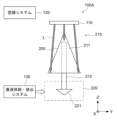
- FIG. 7 is a schematic diagram showing a schematic configuration example of a conventional plant growing apparatus 100A.
- the plant growing device 100A includes a light source (artificial light source) 110 that emits light L used for photosynthesis of plants (for example, agricultural products) 200.
- the light source 110 is arranged above the plants 200 in a space within a plant factory where the plants 200 are grown, and irradiates the plants 200 with light L from above.
- the light used for photosynthesis and the like is sunlight. Sunlight falls from the top of the plant. Therefore, conventional plant factories are often based on reproducing the state of the natural environment.
- the plant growing device 100A can include an air conditioning system 120 that adjusts the temperature, humidity, and carbon dioxide (CO 2 ) concentration of the space within the plant factory to a predetermined state suitable for growing the plants 200. Further, the plant growing device 100A can also include a nutrient solution supply/discharge system 130. In the space inside the plant factory, the area where the plant 200 to be grown is placed is an above-ground space 210 where most of the leaves 211 and stems 212 of the plants 200 are exposed, and the lower part of the stems 212 and roots (tap roots, lateral roots, etc.) It is divided into an underground space 220 where 221 is placed.
- the nutrient solution supply/discharge system 130 has a function of supplying and discharging fertilizer (for example, a culture solution), and supplies and replaces the culture solution to the roots 221 located in the underground space 220.
- FIG. 7 specific components such as a shelf on which the plants 200 are arranged, a support section that supports the plants 200, and a storage section that stores the nutrient solution supplied and discharged by the nutrient solution supply/discharge system 130 are not shown in the illustration. is omitted.
- the above plant growing apparatus 100A has the following problems.
- the light that reaches the leaves that overlap with the leaves that are irradiated with the light or the leaves that are arranged on the lower side of the leaves that are irradiated with the light is less likely to reach the leaves.
- the amount of light decreases. Therefore, a problem arises in that photosynthesis is not sufficiently carried out in the inner leaves of the plant 200 (the leaves closer to the stem) and the lower leaves of the plant 200.
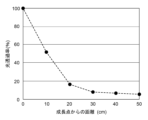
- FIG. 8 is a diagram showing the relationship between the distance from the growing point and the light transmittance when the plant is irradiated with light from above.
- the diagram shown in Figure 8 is the result of investigating how much the illuminance of light at leaves located below is attenuated compared to the illuminance of light irradiated directly on the leaf surface at the growing point.
- the leaf at the growing point is the uppermost leaf of the plant.
- the ratio of the illuminance on the surface of the leaf below the leaf to the illuminance on the surface of the leaf at the growing point is defined as "light transmittance.”
- the plants to be investigated are soybeans (variety: Sachiyutaka) that are planted with a row spacing of 30 cm and are 100 cm tall.
- the light transmittance of leaves 10 cm below the directly irradiated leaf is approximately 50%, and the light transmittance of leaves 20 cm or more below is less than 20%.
- photosynthesis is not sufficiently carried out in the inner leaves of the plant (the leaves closer to the stem) and the lower leaves of the plant.
- FIG. 9 is a diagram showing a light-photosynthesis curve.
- the curve ⁇ shows the light-photosynthesis curve of soybean (variety: Tachinagaha), and the curve ⁇ shows the light-photosynthesis curve of soybean (variety: UA4805).
- the photosynthetic rate at PPFD 800 ⁇ mol ⁇ m ⁇ 2 ⁇ s ⁇ 1 is approximately 22.2 ⁇ mol ⁇ m ⁇ 2 ⁇ s ⁇ 1 .
- FIG. 1(a) The cube shown in FIG. 1(a) is a model showing the occupied space occupied by one plant (crop) in a conventional plant growing apparatus.
- the vertical and horizontal extension (length) of the plant is all assumed to be a, and the volume of the space occupied by the plant is expressed as a3 .
- this is a model in which a plant is spread over an area with a volume of A 3 and is in a state where photosynthesis can occur in the entire area (photosynthesis occurs when it receives light).
- the light irradiation surface when light is irradiated from above the plant, the light irradiation surface is only the upper surface of the space occupied by the plant.
- the cross-sectional area of this light irradiation surface is a 2 (m 2 ). If the irradiance of light on the light irradiation surface is L (w/m 2 ), then the light energy input into the plant occupied space per second is La 2 (J).
- FIG. 1(b) is a model related to a configuration that can improve the problems of the conventional plant growing device described above.
- the model shown in FIG. 1(b) is the same model as in FIG. 1(a), and shows a case in which light is irradiated from the entire surface (ie, six sides) of the plant-occupied space shown as a cube. That is, in this model, light is irradiated not only from the top surface of the plant but also from the four sides and the bottom surface.
- the efficiency of light use by plants is about 80%.
- the total light irradiation cross-sectional area is six times that of the model shown in Figure 1(a), that is, the light input direction is six times larger, which significantly burdens the equipment design. It will be imposed.
- the light does not attenuate until it travels a distance of 0.2a, and that the intensity of the light becomes 0 when the traveling distance exceeds 0.2a.
- the model shown in FIG. 1(c) is a model corresponding to the plant growing device according to the present invention.
- This model restricts the elongation of plants, especially in the lateral direction, and makes the space occupied by one plant a thin rectangular parallelepiped.
- the growth of the plant in the Y direction is restricted, and the space occupied by the plant is shaped like a rectangular parallelepiped with a thickness (in the Y direction) of 0.2a.
- light is irradiated from two opposing sides of a rectangular parallelepiped representing the plant-occupied space.
- the surfaces perpendicular to the Y direction are each used as a light irradiation surface.
- the plant growing device in this embodiment irradiates light from the side (one side or both sides) with respect to the growth direction of the plant.
- the growth direction of a plant refers to an up-down direction (vertical direction).
- the plant growing device in this embodiment limits the thickness of the space occupied by the plant in the direction of light irradiation.
- the amount of attenuation of light traveling in the thickness direction of the plant-occupied space can be suppressed to a small value.
- the design of the equipment can be placed on the back side of the leaves (on the side where the light travels) that is directly irradiated, with a smaller burden on equipment design. It becomes possible to irradiate relatively strong light even to the leaves that are exposed to the leaves, and the efficiency of light use (photosynthesis efficiency) by plants can be improved.
- FIG. 2 is a diagram showing a schematic configuration example of the plant growing apparatus 100 in this embodiment.
- the plant growing device 100 is placed, for example, in a plant factory.
- the temperature, humidity, and carbon dioxide (CO 2 ) concentration of the space inside the plant factory are adjusted to predetermined conditions suitable for growing the plants 200. Therefore, the plant growing device 100 may include an air conditioning system 20 that adjusts the environment in the area where the plants 200 are grown to a temperature, humidity, and carbon dioxide (CO 2 ) concentration suitable for growing the plants 200.
- CO 2 carbon dioxide
- the plants 200 are supported by a plant support section 50.
- the upper side of the plant support section 50 is a space for the stem 212 of the plant 200 to extend and the leaves 211 from the stem 212 to spread out, and most of the leaves 211 and stems 212 of the plant 200 are exposed.
- the lower side of the plant support section 50 is an underground space 220 in which the nutrient solution supply section 31, the lower part of the stem 212, and roots (primary roots, lateral roots, etc.) 221 are arranged, and the nutrient solution 32 is supplied to the roots 221. .
- the nutrient solution supply unit 31 is a container into which a nutrient solution (liquid fertilizer) 32 to be supplied to the roots 221 of the plants 200 is supplied and discharged.
- the nutrient solution 32 is supplied to and discharged from the nutrient solution supply section 31 by a nutrient solution supply/discharge system 30 connected to the nutrient solution supply section 31 .
- the plant growing device 100 in this embodiment is configured to irradiate artificial light L from the side in the growth direction of the plant 200 in the above-ground space 210 of the plant 200.
- the plant growing apparatus 100 in this embodiment is configured to limit the width (thickness) of the plant-occupied space in the above-ground space 210.
- the plant growing device 100 includes a light source (artificial light source) 10A and an extension regulating section 40.
- the light sources 10A are arranged to face each other across the plant 200 in a direction perpendicular to the growth direction 231 of the plant 200 (the Y direction in FIG. 2), and provide artificial light L from both sides with respect to the growth direction 231 of the plant 200. irradiate.
- the elongation regulating section 40 includes a pair of elongation regulating surfaces 40a that are arranged opposite to each other across the plant 200 in the direction of irradiation of the artificial light L (Y direction), and regulate the extension of the plant 200 in the lateral direction (Y direction). That is, the elongation regulating surfaces 40a are arranged on the sides of the plants 200 that are irradiated with the artificial light L, respectively.
- the plant growing device 100 may include a light source (artificial light source) 10B placed above the plant 200.
- the light source 10B irradiates the plant 200 with artificial light L from above.
- the extension regulating section 40 may form a closed space surrounding the plant 200, as shown in FIG. 2. That is, the elongation regulating section 40 may include an elongation regulating surface 40b that is connected to the upper end portions of the pair of elongation regulating surfaces 40a and that regulates the elongation of the plant 200 in the growth direction 231 above the plant 200.
- the shelf on which the plants 200 are placed may be movable.
- the light sources 10A and 10B may be fixed or may be configured to move together with the shelf on which the plants 200 are placed.
- the shelves on which the plants 200 are arranged may be arranged in multiple stages in the vertical direction (Z direction).
- Extension regulation section The elongation regulating section 40 comes into contact with any part of the plant 200 (stem 212 or leaf 211) during the growth process of the plant 200, and limits the elongation of the plant 200 to the space inside the elongation regulating section 40. That is, the elongation regulating section 40 regulates the plant 200 so that it does not spread beyond the space inside the elongation regulating section 40 .
- the elongation regulating section 40 is arranged between the plant 200 and the light sources 10A and 10B.
- the extension regulating section 40 is a light-transmitting member that can transmit the artificial light L emitted from the light sources 10A and 10B, or a light-transmitting member that has a light passage section (an opening through which light passes) through which the artificial light L can pass. It is composed of a permeable member.
- the light emitted from the light sources 10A and 10B is irradiated onto the plant 200 via the elongation suppressing section 40.
- the elongation regulating section 40 can be made of a glass member that transmits light irradiated onto the plant 200, a transparent resin member such as an acrylic member or a PET member, or the like. Further, for example, the elongation regulating section 40 may be composed of a net (for example, a wire mesh), a punching board, or the like.
- the pair of elongation regulating surfaces 40a arranged opposite to each other in the Y direction with the plant 200 in between are two surfaces parallel or substantially parallel to the XZ plane.
- the width w in the Y direction of the elongation regulating section 40 (the separation width between the pair of elongation regulating surfaces 40a) is the occupied area occupied by one plant 200 when the plant 200 grows without the elongation regulating section 40 provided. (w ⁇ W). Therefore, during the growth process, the plant 200 comes into contact with the elongation regulating surfaces 40a arranged to face each other in the Y direction, and the elongation in the Y direction is regulated. Note that details of the width w in the Y direction of the extension regulating portion 40 will be described later.
- the elongation regulating surface 40b arranged above the plant 200 is a surface parallel or substantially parallel to the XY plane.
- the height h of the extension regulating section 40 in the Z direction (installation height of the extension regulating surface 40b) is the occupied area occupied by one plant 200 when the plant 200 grows without the extension regulating section 40 provided. (h ⁇ H). Therefore, during the growth process, the plant 200 comes into contact with the elongation regulating surface 40b arranged above the plant 200, and its elongation (growth) in the Z direction is regulated. Note that details of the height h in the Z direction of the extension regulating portion 40 will be described later.
- the light source 10A is provided so that its light-emitting surface faces a side surface of the plant 200 (a surface parallel to the XZ plane in FIG. 2), and irradiates the side surface of the plant 200 with artificial light L. In this way, by irradiating the artificial light L from the side with respect to the growth direction (Z direction) of the plant 200, the leaves 211 located at the upper part of the plant 200 and the leaves 211 located at the lower part of the plant 200 are illuminated. It is possible to irradiate light with the same amount of light.
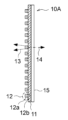
- the light source 10A may be a surface emitting source in which a plurality of LEDs 12 are arranged on a flat support 11, for example, as shown in FIG. 3(a).
- the LED 12 mainly includes an LED chip 12a that emits light, and an LED board 12b that supplies power from a power supply device (not shown) to the LED chip 12a.
- These plurality of LEDs 12 can be arranged in a grid pattern on the support body 11, as shown in FIG. 3(b), which is a view taken in the direction of arrow A in FIG. 3(a).
- the support 11 may be, for example, an acrylic plate.
- the light source 10A light is emitted from the LED chip 12a, and heat is radiated from the LED board 12b as power is supplied to the LED chip 12a. That is, the light emitting direction 13 in which light is emitted and the heat radiation direction 14 are opposite to each other.
- the plurality of LEDs 12 may emit light with different wavelengths. Further, depending on the growth stage of the plant 200, light of different wavelengths may be irradiated as appropriate.
- the light source 10B is provided so that its light emitting surface faces the upper surface of the plant 200 (a surface parallel to the XY plane in FIG. 2), and irradiates the upper surface of the plant 200 with artificial light L.
- the configuration of the light source 10B can be similar to that of the light source 10A.
- a heat dissipation member 15 such as a heat sink may be arranged on the surface of the support 11 opposite to the surface on which the LEDs 12 are arranged.
- the support that supports the LED 12 is not limited to the flat shape as described above, and the support surface may have a curved surface.
- the light source 10A may have a configuration in which a plurality of LEDs 12 are arranged on a corrugated support 11a.
- the surface area of the LED installation surface is increased compared to the flat support 11, so it is possible to install more LEDs 12.
- the surface area of the surface from which heat from the LEDs 12 is radiated increases, even if the number of LEDs 12 increases, it is possible to radiate heat efficiently.
- the light source 10A may have a configuration in which a plurality of lamp light sources each having a cylindrical light emitting surface are arranged in parallel.
- FIG. 2 shows an example in which the light sources 10A and 10B are arranged outside the extension regulating section 40 (on the opposite side from the plant 200), the arrangement of the light sources 10A and 10B is not limited to the above.
- the light sources 10A and 10B may be arranged inside the extension regulating section 40 and between the extension regulating section 40 and the plant 200. In this case, since there are no inclusions between the light sources 10A, 10B and the plants 200, it becomes possible to irradiate the plants 200 with light more efficiently.
- LED light sources can be used as the light sources 10A and 10B.
- the light sources 10A and 10B are arranged inside the extension regulating section 40, the light sources 10A and 10B are arranged relatively close to the plant 200, so that humidity such as transpiration flow from the leaves of the plant 200 is prevented. will be more affected. Therefore, when the light sources 10A and 10B are LED light sources, the LED surfaces may be waterproofed to reduce the influence of humidity on the LEDs.
- the support body on which the plurality of LEDs 12 constituting the light source 10A are arranged may also be used as the extension regulating section 40. That is, a plurality of LEDs 12 may be provided on the inner surface of the extension regulating section 40.
- the light source 10A for example, a film-type LED may be used, and the film may be bonded to the inner surface of the elongation regulating portion 40.
- the light source 10B for example, the plant 200 comes into contact with the LED 12 as the plant 200 extends.
- the heat radiation direction 14 from the LED 12 is opposite to the light emission direction 13 of the LED 12, heating of the plant 200 due to the heat of the LED 12 is suppressed, and malfunction of the plant due to heat is suppressed.
- the light sources 10A are arranged facing each other in the Y direction with the plants 200 in between, but the light sources 10 may be arranged only on one side with respect to the plants 200. good.
- the light source 10B is arranged above the plant, but the light source 10B does not need to be arranged.
- the extension regulating section 40 when the light sources 10A and 10B are arranged inside the extension regulating section 40 and the extension regulating section 40 on the side where the light sources 10A and 10B are not arranged have light transmittance and light transmittance. You don't have to.
- the width (thickness) w in the Y direction of the elongation regulating section 40 is set so that the amount of attenuation of light traveling through the space occupied by the plant defined by the elongating regulating section 40 is as small as possible, as explained in the model shown in FIG. 1(c). is set to For example, the width w of the elongation regulating portion 40, that is, the separation width w between the pair of elongation regulating surfaces 40a, is the sum of the leaf areas of all the leaves 211 of the plant 200 between the pair of elongating regulating surfaces 40a. It may be set based on an index value converted per unit light irradiation area.
- Leaf Area Index is an index that indicates radiation absorption, photosynthesis/transpiration, carbon absorption capacity, etc. of vegetation.
- LAI is defined as the total projected area of leaves per unit ground surface area (for example, 1 m 2 ) of a vegetation community, assuming that the vegetation is irradiated with light from above.
- the width w of the elongation regulating portion 40 is determined by integrating the leaf areas of all the leaves 211 of the plant 200 between the pair of elongation regulating surfaces 40a per unit area of the elongation regulating surfaces 40a.
- the converted index value may be set to be less than 4. If the index value is less than 4, the input light energy can be used effectively without loss.
- the above index value is set to be less than 2.
- the width w of the extension restricting portion 40 may be set to .
- the width w of the elongation regulating portion 40 is set to be larger than the thickness of the stem 212 of the plant 200 or the size of the harvested product.
- the height h in the Z direction and the depth in the X direction of the extension regulating portion 40 are not particularly limited.
- the height h and depth in the Z direction of the expansion restriction section 40 that is, the size of the expansion restriction surface 40a, may be the same or approximately the same as the size of the light emitting surface of the light source 10A.
- the entire surface of the elongation regulating surface 40a can be used as a light irradiation surface, and the plant 200 whose growth in the Z direction is regulated by the elongation regulating section 40 is entirely irradiated with light from the light source 10A. Can be done.
- the depth of the extension regulating portion 40 in the X direction may be, for example, the same or approximately the same as the depth of the shelf on which the plants 200 are placed in the X direction.
- the plants 200 may be planted in a row in the X direction.
- the distance between the plants 200 is such that the depth in the X direction of the space occupied by one plant 200 defined by the extension regulating section 40 is wider than the width w in the Y direction of the space occupied by one plant. Set the interval.
- the PPFD of the artificial light emitted from the light source 10A is set to a value that allows the plants 200 to photosynthesize efficiently.
- the light compensation point can be said to be the minimum amount of energy required for plant growth.
- the light compensation point is 50 ⁇ mol ⁇ m ⁇ 2 ⁇ s ⁇ 1 or less. Therefore, the lower limit value of PPFD of the light emitted from the light source 10A may be set to the lower limit value of 50 ⁇ mol ⁇ m ⁇ 2 ⁇ s ⁇ 1 .
- the plant growing device 100 includes a light source 10A that irradiates artificial light from the side in the growth direction of the plant 200, and an elongation regulating section that regulates the lateral elongation of the plant 200. 40.
- the light sources 10A are arranged opposite to each other with the plant 200 in between, and irradiate artificial light from both sides with respect to the growth direction of the plant 200.
- the elongation regulating section 40 has a pair of elongation regulating surfaces 40a that are arranged to face each other across the plant 200 in the irradiation direction of the artificial light from the light source 10A, and that regulate the lateral extension of the plant 200.
- the space occupied by one plant 200 defined by the elongation regulating section 40 is made into a rectangular parallelepiped shape in which the depth in the X direction is wider than the width (thickness) in the Y direction, which is the direction of light irradiation. Can be done. Thereby, the growth of the plant 200 that is restricted in the Y direction by the pair of growth restriction surfaces 40a can be allowed in the X direction, and the plant 200 can be grown appropriately.
- the separation width between the pair of elongation regulating surfaces 40a is determined by an index value obtained by converting the cumulative leaf area of all leaves of the plant 200 existing between the pair of elongation regulating surfaces 40a per unit area of the elongation regulating surfaces 40a.
- the distance can be less than 4. Thereby, the artificial light irradiated onto the plant 200 can be effectively used without wasting it.
- the PPFD of the artificial light emitted from the light source 10A should be 400 ⁇ mol ⁇ m ⁇ 2 ⁇ s ⁇ 1 or more and 2000 ⁇ mol ⁇ m ⁇ 2 ⁇ s ⁇ 1 or less, preferably 1000 ⁇ mol ⁇ m ⁇ 2 ⁇ s ⁇ 1 or less. Can be done.
- PPDF By setting PPDF to 400 ⁇ mol ⁇ m ⁇ 2 ⁇ s ⁇ 1 , for example, in the case of soybeans, photosynthetic efficiency can be maximized and productivity can be further improved.
- the PPFD by setting the PPFD to 2000 ⁇ mol ⁇ m ⁇ 2 ⁇ s ⁇ 1 or less, it is possible to irradiate light that is less than the PPFD of sunlight on a clear day, and it is possible to appropriately avoid adverse effects on plants. can. Further, when the PPFD is set to 1000 ⁇ mol ⁇ m ⁇ 2 ⁇ s ⁇ 1 or less, the production rate (growth rate) of the plants 200 can be increased while suppressing the decrease in photosynthetic efficiency to an acceptable range.
- the productivity of plants per unit space can be further improved.
- plants can be grown efficiently while minimizing the burden of equipment design.
- the plant 200 to be grown is a legume such as a soybean, but the plant 200 is not limited to legumes.
- the elongation regulating section 40 comes into contact with any part of the plant 200 (leaves 211, stems 212, etc.) and regulates the elongation of the plant 200.
- the shape of the portion that comes into contact with the extension regulating portion 40 is forcibly changed. Therefore, it is preferable that the plant 200 to be grown is a plant that is allowed to change its shape as described above.
- 10A, 10B ...Artificial light source, 11...Support, 12...LED, 20...Air conditioning system, 30...Nutritional solution supply/discharge system, 40...Elongation regulation section, 100...Plant growth device, 200...Plant, 210...Aerial part Space, 211...Leaf, 212...Stem, 220...Underground space, 221...Root, 231...Growth direction, 232...Elongation direction
Landscapes
- Life Sciences & Earth Sciences (AREA)
- Environmental Sciences (AREA)
- Biodiversity & Conservation Biology (AREA)
- Botany (AREA)
- Ecology (AREA)
- Forests & Forestry (AREA)
- Cultivation Of Plants (AREA)
Abstract
コストを抑えつつ、単位空間あたりの植物の生産性をより向上させることができる植物育成装置および植物育成方法を提供する。 植物育成装置100は、人工光により植物を育成する。植物育成装置100は、植物200の成長方向(Z方向)に対して側方から人工光を照射する光源10Aと、人工光の照射方向において植物200を挟んで対向配置され、植物200の側方への伸長を規制する一対の伸長規制面40aを有する伸長規制部40と、を備える。光源10Aは、植物200を挟んで対向配置され、植物200の成長方向に対して両側方から人工光を照射してもよい。
Description
本発明は、人工光により植物を育成する植物育成装置および植物育成方法に関する。
近年、世界的に人口増の傾向にあり、2050年までに世界人口は90億人に達すると予測されている。そのため、将来は食料不足の問題の懸念がある。
このような食料不足への対応の一つとして、農作物を増産し、一年中安定に収穫できるようにすることが期待されている。特に、動物性たんぱく質の代替としての植物性たんぱく質の確保は重要な課題である。
このような食料不足への対応の一つとして、農作物を増産し、一年中安定に収穫できるようにすることが期待されている。特に、動物性たんぱく質の代替としての植物性たんぱく質の確保は重要な課題である。
農作物の増産および安定収穫を実現するための方策として、施設園芸農業や植物工場が検討されてきている。更に植物工場においては、従来の農業のように広大な土地が確保できなくても比較的狭い空間で農作物を安定量生産することが可能な、垂直農業の採用も検討されている。
植物工場においては、人工光源から農作物に照射される光合成のための光の強度や、植物育成空間における温度、湿度、二酸化炭素(CO2)濃度、風速といった環境条件、植物成長のための肥料成分といった各パラメータを制御することが可能である。そのため、農作物の周年生産を行うことができ、農作物の生産性を飛躍的に高めることが可能である。
植物工場においては、人工光源から農作物に照射される光合成のための光の強度や、植物育成空間における温度、湿度、二酸化炭素(CO2)濃度、風速といった環境条件、植物成長のための肥料成分といった各パラメータを制御することが可能である。そのため、農作物の周年生産を行うことができ、農作物の生産性を飛躍的に高めることが可能である。
例えば特許文献1は、太陽光を用いずにLED光などの人工光を照射して植物を栽培する閉鎖型植物工場を開示する。この閉鎖型植物工場では、植物体の側面から光を近接照射することで、トマトやキュウリなどの垂直方向に伸長して草丈の高くなる野菜でも栽培することができるようにしている。
しかしながら、植物工場には経済性の課題があり、現状、大規模な普及には至っていない。植物工場自体の建設コスト、LEDなどを備える人工光源装置や環境条件を調整するための空調等のランニングコストは数億円程度かかり、ビニールハウス等を用いる施設園芸農業と比較しても10倍前後の費用が発生する。
よって、植物工場においては、より効率的に植物を育成することが可能な植物育成装置(システム)を導入することが望まれる。
よって、植物工場においては、より効率的に植物を育成することが可能な植物育成装置(システム)を導入することが望まれる。
そこで、本発明は、コストを抑えつつ、単位空間あたりの植物の生産性をより向上させることができる植物育成装置および植物育成方法を提供することを課題としている。
上記課題を解決するために、本発明に係る植物育成装置の一態様は、人工光により植物を育成する植物育成装置であって、前記植物の成長方向に対して側方から前記人工光を照射する人工光源と、前記人工光の照射方向において前記植物を挟んで対向配置され、前記植物の前記側方への伸長を規制する一対の伸長規制面を有する伸長規制部と、を備える。
このように、植物の成長方向(上下方向)に対して側方から光を照射するので、植物の上部のみならず植物の下部に位置する葉に対しても適切な光量の光を照射することができる。また、伸長規制部によって光の照射方向における植物の伸長を規制し、当該照射方向における植物の占有空間の幅(厚み)を制限するので、人工光源からの光が直接照射される葉の裏側(光が進行する側)に配置される葉にも比較的強度の強い光を照射することが可能となる。したがって、設備の設計の負担を抑えた状態で、植物による光の利用効率(光合成効率)を高めることができる。
また、上記の植物育成装置において、前記人工光源は、前記植物を挟んで対向配置され、前記植物の成長方向に対して両側方から前記人工光を照射してもよい。
この場合、植物に対してより効率的に光を照射することができる。
この場合、植物に対してより効率的に光を照射することができる。
さらに、上記の植物育成装置において、前記一対の伸長規制面の離隔幅は、該一対の伸長規制面の間に存在する前記植物のすべての葉の積算葉面積を前記伸長規制面の単位面積あたりに換算した指標値が、4未満となる距離であってよい。
この場合、植物に照射された人工光を無駄にすることなく有効活用することができる。
この場合、植物に照射された人工光を無駄にすることなく有効活用することができる。
また、上記の植物育成装置において、前記一対の伸長規制面の離隔幅は、前記植物から収穫される収穫物の大きさ以上に設定されていてもよい。
この場合、収穫物を潰すことなく栽培することができる。
この場合、収穫物を潰すことなく栽培することができる。
また、上記の植物育成装置において、前記伸長規制部は、前記植物を取り囲む閉鎖空間を形成していてもよい。
この場合、植物の占有空間の幅(厚み)、高さおよび奥行を適切に規定することができる。
この場合、植物の占有空間の幅(厚み)、高さおよび奥行を適切に規定することができる。
さらに、上記の植物育成装置において、前記伸長規制部により規定される前記植物の1株分の占有空間の前記人工光の照射方向における幅は、当該1株分の占有空間の奥行よりも狭くてもよい。
この場合、伸長規制部の幅方向の伸長を規制し、奥行方向の伸長を妨げないようにすることができるので、植物を適切に育成させることができる。
この場合、伸長規制部の幅方向の伸長を規制し、奥行方向の伸長を妨げないようにすることができるので、植物を適切に育成させることができる。
さらにまた、上記の植物育成装置において、前記伸長規制面の大きさは、前記人工光源の発光面の大きさと同等であり、前記伸長規制面の全面が前記人工光の照射面となっていてもよい。
この場合、伸長規制部により規定される植物の占有空間内に適切に光を照射することができる。
この場合、伸長規制部により規定される植物の占有空間内に適切に光を照射することができる。
また、上記の植物育成装置において、前記人工光源から放出される人工光の光合成光量子束密度(PPFD)が400μmol・m-2・s-1以上であってよい。
この場合、例えば大豆の光合成効率を最大にすることができ、生産性をより向上させることができる。
この場合、例えば大豆の光合成効率を最大にすることができ、生産性をより向上させることができる。
さらに、上記の植物育成装置において、前記人工光源から放出される人工光の光合成光量子束密度(PPFD)が2000μmol・m-2・s-1以下であってよい。
快晴時の太陽光のPPFDを人工光源から放出される人工光の上限値とすることで、植物への悪影響を適切に回避することができる。
快晴時の太陽光のPPFDを人工光源から放出される人工光の上限値とすることで、植物への悪影響を適切に回避することができる。
また、上記の植物育成装置において、前記人工光源から放出される人工光の光合成光量子束密度(PPFD)が1000μmol・m-2・s-1以下であってもよい。
この場合、光合成効率の低下を許容できる範囲に抑えつつ、植物の生産速度(成長速度)を速めることができる。
この場合、光合成効率の低下を許容できる範囲に抑えつつ、植物の生産速度(成長速度)を速めることができる。
また、上記の植物育成装置において、前記伸長規制面は、前記植物と前記人工光源との間に配置されており、前記人工光を透過可能な光透過性の部材、または、前記人工光を通過可能な光通過性の部材により構成されていてもよい。
この場合、人工光源から放出される光を、伸長規制部を介して適切に植物に照射することができる。また、植物が人工光源と接触することを回避できるので、人工光源の熱による植物の不具合を抑制することができる。
この場合、人工光源から放出される光を、伸長規制部を介して適切に植物に照射することができる。また、植物が人工光源と接触することを回避できるので、人工光源の熱による植物の不具合を抑制することができる。
さらに、上記の植物育成装置において、前記人工光源は、前記伸長規制面の表面に設けられていてもよい。
この場合、伸長規制部を、人工光源を支持する支持体として兼用することができるので、部品点数を削減し、装置の小型化を実現することができる。
この場合、伸長規制部を、人工光源を支持する支持体として兼用することができるので、部品点数を削減し、装置の小型化を実現することができる。
また、上記の植物育成装置において、前記伸長規制面は、平板状または波板状の板状体であり、前記板状体の表面に前記人工光源が設けられていてもよい。
この場合、伸長規制部によって人工光源を適切に支持し、植物に対して適切に光を照射することができる。また、伸長規制部が波板状の板状体である場合、平板状の場合と比較して光源設置面の表面積が増加するため、人工光源をより多く設置することが可能となる。また、光源からの熱が放熱される面の表面積も増加するので、人工光源の数が増加しても効率良く放熱することが可能となる。
この場合、伸長規制部によって人工光源を適切に支持し、植物に対して適切に光を照射することができる。また、伸長規制部が波板状の板状体である場合、平板状の場合と比較して光源設置面の表面積が増加するため、人工光源をより多く設置することが可能となる。また、光源からの熱が放熱される面の表面積も増加するので、人工光源の数が増加しても効率良く放熱することが可能となる。
さらにまた、上記の植物育成装置は、前記人工光源からの前記人工光の放射方向とは反対側に、前記人工光源が発する熱を排熱する排熱機構を備えていてもよい。
この場合、人工光源が発する熱による植物の不具合をより適切に抑制することができる。
この場合、人工光源が発する熱による植物の不具合をより適切に抑制することができる。
また、本発明に係る植物育成方法の一態様は、人工光により植物を育成する植物育成方法であって、前記植物の成長方向に対して側方から前記人工光を照射する工程と、前記人工光の照射方向における前記植物の前記側方への伸長を規制する工程と、を含む。
このように、植物の成長方向に対して側方から光を照射するので、植物の上部のみならず植物の下部に位置する葉に対しても適切な光量の光を照射することができる。また、光の照射方向における植物の伸長を規制し、当該照射方向における植物の占有空間の幅(厚み)を制限するので、人工光源からの光が直接照射される葉の裏側(光が進行する側)に配置される葉にも比較的強度の強い光を照射することが可能となる。したがって、設備の設計の負担を抑えた状態で、植物による光の利用効率(光合成効率)を高めることができる。
本発明では、コストを抑えつつ、単位空間あたりの植物の生産性をより向上させることができる。
以下、本発明の実施形態を図面に基づいて説明する。
本実施形態では、人工光により植物を育成する植物育成装置について説明する。本実施形態における植物育成装置は、例えば植物工場内に配置される。
ここで、上記植物は、例えば豆類(未成熟/種実)などの農作物とすることができる。
本実施形態では、人工光により植物を育成する植物育成装置について説明する。本実施形態における植物育成装置は、例えば植物工場内に配置される。
ここで、上記植物は、例えば豆類(未成熟/種実)などの農作物とすることができる。
まず、従来の植物育成装置について説明する。
図7は、従来の植物育成装置100Aの概略構成例を示す模式図である。
植物育成装置100Aは、植物(例えば農作物)200の光合成等に利用される光Lを放出する光源(人工光源)110を備える。光源110は、植物200が育成される植物工場内空間における植物200の上方に配置され、植物200の上方から光Lを照射する。
自然環境にて成長する植物(例えば農作物)の場合、光合成等に利用される光は太陽光である。太陽光は、植物の上部から降り注いでいる。よって、従来の植物工場においても、この自然環境の状態を再現することを基本としていることが多い。
図7は、従来の植物育成装置100Aの概略構成例を示す模式図である。
植物育成装置100Aは、植物(例えば農作物)200の光合成等に利用される光Lを放出する光源(人工光源)110を備える。光源110は、植物200が育成される植物工場内空間における植物200の上方に配置され、植物200の上方から光Lを照射する。
自然環境にて成長する植物(例えば農作物)の場合、光合成等に利用される光は太陽光である。太陽光は、植物の上部から降り注いでいる。よって、従来の植物工場においても、この自然環境の状態を再現することを基本としていることが多い。
植物育成装置100Aは、植物工場内空間の温度、湿度、二酸化炭素(CO2)濃度が、植物200の育成に適した所定の状態となるように調整する空調システム120を備えることができる。
また、植物育成装置100Aは、養液供給・排出システム130を備えることもできる。植物工場内空間において、育成対象の植物200が配置される領域は、植物200の葉211や茎212の大部分が露出する地上部空間210と、茎212の下部および根(主根、側根など)221が配置される地下部空間220とに分割される。養液供給・排出システム130は、肥料(例えば、培養液)を供給したり、排出したりする機能を有し、地下部空間220に位置する根221に対する培養液の供給と入れ替えとを行う。
また、植物育成装置100Aは、養液供給・排出システム130を備えることもできる。植物工場内空間において、育成対象の植物200が配置される領域は、植物200の葉211や茎212の大部分が露出する地上部空間210と、茎212の下部および根(主根、側根など)221が配置される地下部空間220とに分割される。養液供給・排出システム130は、肥料(例えば、培養液)を供給したり、排出したりする機能を有し、地下部空間220に位置する根221に対する培養液の供給と入れ替えとを行う。
なお、図7において、植物200が配置される棚、植物200を支える支持部、養液供給・排出システム130により供給および排出される養液を貯蔵する貯蔵部といった具体的な構成物は、図示を省略している。
上記の植物育成装置100Aにおいては、以下の問題点がある。
〔問題点1〕
植物200は、成長につれ上下方向(Z方向)および左右方向(X方向、Y方向)に伸長する。図7に示すように光源110を植物200の上方に設置し、植物200の上方から光Lを照射した場合、光Lは、まず植物200の最上部にある葉に到達する。しかしながら、最上部の葉の内側や当該葉の下側(植物200の下部)には、光Lは到達しづらい。
すなわち、光が確実に照射される植物200の上部に位置する葉に比べ、当該光照射される葉と重なり合った葉や、当該光照射される葉の下側に配置される葉に到達する光の光量は低下する。そのため、植物200の内側の葉(茎に近い側の葉)や植物200の下側の葉における光合成が十分に行われないという問題が生じる。
〔問題点1〕
植物200は、成長につれ上下方向(Z方向)および左右方向(X方向、Y方向)に伸長する。図7に示すように光源110を植物200の上方に設置し、植物200の上方から光Lを照射した場合、光Lは、まず植物200の最上部にある葉に到達する。しかしながら、最上部の葉の内側や当該葉の下側(植物200の下部)には、光Lは到達しづらい。
すなわち、光が確実に照射される植物200の上部に位置する葉に比べ、当該光照射される葉と重なり合った葉や、当該光照射される葉の下側に配置される葉に到達する光の光量は低下する。そのため、植物200の内側の葉(茎に近い側の葉)や植物200の下側の葉における光合成が十分に行われないという問題が生じる。
図8は、植物の上方から光照射した場合の成長点からの距離と光透過率との関係を示す図である。
この図8に示す図は、成長点にある葉の表面に直接照射される光の照度に対して、下側に配置される葉における光の照度がどの程度減衰するかを調査した結果である。ここで、成長点にある葉とは、植物の最上部の葉である。
この図8では、成長点にある葉の表面における照度に対する、当該葉の下側の葉の表面における照度の比を「光透過率」として定義している。また、調査対象の植物は、条間30cmで植えられていて、背丈が100cmである大豆(品種:サチユタカ)としている。
この図8に示す図は、成長点にある葉の表面に直接照射される光の照度に対して、下側に配置される葉における光の照度がどの程度減衰するかを調査した結果である。ここで、成長点にある葉とは、植物の最上部の葉である。
この図8では、成長点にある葉の表面における照度に対する、当該葉の下側の葉の表面における照度の比を「光透過率」として定義している。また、調査対象の植物は、条間30cmで植えられていて、背丈が100cmである大豆(品種:サチユタカ)としている。
図8に示すように、直接光照射される葉(成長点にある葉)から10cm下側の葉における光透過率は約50%であり、20cm以上下側にある葉においては、光透過率は20%以下となっている。本測定からも明らかなように、植物の内側の葉(茎に近い側の葉)や植物の下側の葉における光合成は、十分に行われていない。
〔問題点2〕
植物(農作物)に照射する光の光合成有効光量子束密度(Photosynthetic Photon Flux density:PPFD)と光合成効率との関係は、必ずしも線形の関係ではないことが知られている。
図9は、光-光合成曲線を示す図である。この図9において、曲線αは大豆(品種:タチナガハ)の光-光合成曲線、曲線βは大豆(品種:UA4805)の光-光合成曲線を示している。
この図9に示す光-光合成曲線は、品種ごとにPPFD=0,50,100,200,400,600,800,1200,2000μmol・m-2・s-1のときの光合成速度を測定した結果である。
植物(農作物)に照射する光の光合成有効光量子束密度(Photosynthetic Photon Flux density:PPFD)と光合成効率との関係は、必ずしも線形の関係ではないことが知られている。
図9は、光-光合成曲線を示す図である。この図9において、曲線αは大豆(品種:タチナガハ)の光-光合成曲線、曲線βは大豆(品種:UA4805)の光-光合成曲線を示している。
この図9に示す光-光合成曲線は、品種ごとにPPFD=0,50,100,200,400,600,800,1200,2000μmol・m-2・s-1のときの光合成速度を測定した結果である。
この図9に示すように、大豆の場合、PPFD=400μmol・m-2・s-1以下では光-光合成曲線が略線形となる。つまり、大豆の場合は、最大の効率でかつ最大量(最速成長)の光合成が行えるPPFDが400μmol・m-2・s-1である。そこで、PPFD=400μmol・m-2・s-1に対する光合成速度=約15μmol・m-2・s-1を光合成効率100%として定義する。
光-光合成曲線が線形であれば、PPFD=800μmol・m-2・s-1に対する光合成速度は約30μmol・m-2・s-1となるはずである。しかしながら、実際は、光-光合成曲線は飽和傾向にあり、曲線αの場合、PPFD=800μmol・m-2・s-1での光合成速度は約22.2μmol・m-2・s-1となっている。つまり、PPFD=800μmol・m-2・s-1での光合成効率は約74%となる。同様に、PPFD=1000μmol・m-2・s-1での光合成効率は約64%となる。
なお、図9に示す特性は、大豆のみならず、他の農作物にも当てはまる傾向にある。
光-光合成曲線が線形であれば、PPFD=800μmol・m-2・s-1に対する光合成速度は約30μmol・m-2・s-1となるはずである。しかしながら、実際は、光-光合成曲線は飽和傾向にあり、曲線αの場合、PPFD=800μmol・m-2・s-1での光合成速度は約22.2μmol・m-2・s-1となっている。つまり、PPFD=800μmol・m-2・s-1での光合成効率は約74%となる。同様に、PPFD=1000μmol・m-2・s-1での光合成効率は約64%となる。
なお、図9に示す特性は、大豆のみならず、他の農作物にも当てはまる傾向にある。
このように、光強度が高くなると光合成速度はある一定以上にはならなくなる。つまり、植物の内側の葉(茎に近い側の葉)や植物の下側の葉に十分な強度の光を導光するために、光源から放出される光のピーク強度を増大させても、最上部の葉における光合成効率はいずれ飽和状態に達する。そのため、光源に投入する電力の一部は無駄な電力となってしまう。
以下、本発明の概要(考え方)について説明する。
図1(a)に示す立方体は、従来の植物育成装置において植物(農作物)1株が占有する占有空間を示すモデルである。本モデルは、植物の上下および左右の伸長(長さ)を全てaとして仮想したものであり、植物占有空間の体積はa3として表される。つまり、植物は体積a3の領域に広がっており、その全領域で光合成が行える(光を受ければ光合成が行われる)状態になっているモデルである。
図1(a)に示す立方体は、従来の植物育成装置において植物(農作物)1株が占有する占有空間を示すモデルである。本モデルは、植物の上下および左右の伸長(長さ)を全てaとして仮想したものであり、植物占有空間の体積はa3として表される。つまり、植物は体積a3の領域に広がっており、その全領域で光合成が行える(光を受ければ光合成が行われる)状態になっているモデルである。
図1(a)に示すように、植物の上方から光を照射した場合、光照射面は植物占有空間の上面のみとなる。この光照射面の断面積はa2(m2)である。
光照射面における光の放射照度をL(w/m2)とすると、植物占有空間に対して1秒間に投入される光エネルギーは、La2(J)となる。
光照射面における光の放射照度をL(w/m2)とすると、植物占有空間に対して1秒間に投入される光エネルギーは、La2(J)となる。
上記したように、光合成等のための光が植物の上方から照射される場合、植物の下側に位置する葉(直接光照射される葉と重なりあった葉や直接光照射される葉から光進行方向にある程度離隔している葉)に到達する光の光量は低下する。
ここで仮に、植物の最上部の葉から下方に0.2a進行した場所での光の放射照度が0になると仮定すると、実際に植物占有空間にて光合成が行われる領域は、0.2a3となる。すなわち、植物の光合成能力の利用効率は20%となる。
なお、実際は、光は照射面から0.2a進行するにつれて徐々に減衰するので、投入したエネルギーの減衰を考慮すると植物による光の利用効率は20%を下回る。しかしながら、ここでは理解を容易にするために、光は0.2aの距離だけ進むまでは減衰せず、進行距離が0.2aを越えたら、光の強度が0となると仮定している。
ここで仮に、植物の最上部の葉から下方に0.2a進行した場所での光の放射照度が0になると仮定すると、実際に植物占有空間にて光合成が行われる領域は、0.2a3となる。すなわち、植物の光合成能力の利用効率は20%となる。
なお、実際は、光は照射面から0.2a進行するにつれて徐々に減衰するので、投入したエネルギーの減衰を考慮すると植物による光の利用効率は20%を下回る。しかしながら、ここでは理解を容易にするために、光は0.2aの距離だけ進むまでは減衰せず、進行距離が0.2aを越えたら、光の強度が0となると仮定している。
図1(b)は、上記従来の植物育成装置の問題点の改善を実現しうる構成に関するモデルである。図1(b)に示すモデルは、図1(a)と同様のモデルであり、立方体で示す植物占有空間について、全面(すなわち6面)より光照射するケースを示す。
すなわち、本モデルでは、植物の上面のみならず、4側面および下面より光照射するものである。
図1(b)に示すモデルでは、植物占有空間を示す立方体の6面方向から光が照射されるので、総光照射断面積は6×a2=6a2(m2)となる。よって、光照射面における光の放射照度をL(w/m2)とすると、植物占有空間に対して1秒間に投入される光エネルギーは、6La2(J)となる。
すなわち、本モデルでは、植物の上面のみならず、4側面および下面より光照射するものである。
図1(b)に示すモデルでは、植物占有空間を示す立方体の6面方向から光が照射されるので、総光照射断面積は6×a2=6a2(m2)となる。よって、光照射面における光の放射照度をL(w/m2)とすると、植物占有空間に対して1秒間に投入される光エネルギーは、6La2(J)となる。
ここでも同様に、植物の最上部の葉から下方に0.2a進行した場所での光の放射照度が0になると仮定すると、実際に植物占有空間にて光合成が行われる領域は、a3-(0.6a)3=0.784a3となる。すなわち、植物による光の利用効率は約80%となる。
ただし、図1(b)に示すモデルでは、総光照射断面積が図1(a)に示すモデルの6倍、即ち光の投入方向が6倍になっており、著しく設備の設計に負担を課すことになる。
また、ここまで設備に負担を課しても、植物による光の利用効率を100%にすることができていない。
なお、ここでも、理解を容易にするために、光は0.2aの距離だけ進むまでは減衰せず、進行距離が0.2aを越えたら光の強度が0となると仮定している。
ただし、図1(b)に示すモデルでは、総光照射断面積が図1(a)に示すモデルの6倍、即ち光の投入方向が6倍になっており、著しく設備の設計に負担を課すことになる。
また、ここまで設備に負担を課しても、植物による光の利用効率を100%にすることができていない。
なお、ここでも、理解を容易にするために、光は0.2aの距離だけ進むまでは減衰せず、進行距離が0.2aを越えたら光の強度が0となると仮定している。
図1(c)に示すモデルは、本発明に係る植物育成装置に対応するモデルである。
本モデルは、植物の特に側面方向への伸長を規制して、植物1株の占有空間を厚みの薄い直方体にするものである。図1(c)に示す例では、Y方向への植物の伸長を規制し、植物の占有空間を、厚み(Y方向)を0.2aとした直方体形状としている。
図1(c)に示すモデルでは、植物占有空間を示す直方体のうち、対向する2側面から光を照射している。具体的には、Y方向に対して直交する面をそれぞれ光照射面としている。この場合、総光照射断面積は2×5a×a=10a2となる。よって、光照射面における光の放射照度をL(w/m2)とすると、植物占有空間に対して1秒間に投入される投入される光エネルギーは、10La2(J)となる。
本モデルは、植物の特に側面方向への伸長を規制して、植物1株の占有空間を厚みの薄い直方体にするものである。図1(c)に示す例では、Y方向への植物の伸長を規制し、植物の占有空間を、厚み(Y方向)を0.2aとした直方体形状としている。
図1(c)に示すモデルでは、植物占有空間を示す直方体のうち、対向する2側面から光を照射している。具体的には、Y方向に対して直交する面をそれぞれ光照射面としている。この場合、総光照射断面積は2×5a×a=10a2となる。よって、光照射面における光の放射照度をL(w/m2)とすると、植物占有空間に対して1秒間に投入される投入される光エネルギーは、10La2(J)となる。
ここでも、図1(a)および図1(b)の場合と同様、光が直接照射される葉から0.2a進行した場所での放射照度が0になると仮定する。また、理解を容易にするために、光は0.2aの距離だけ進むまでは減衰せず、進行距離が0.2aを越えたら光の強度が0となると仮定する。
図1(c)に示すモデルでは、植物占有空間の厚み(Y方向)は0.2aに制限されているため、一方の側面(Y方向に垂直な側面)から投入される光は、全て植物に利用される。すなわち、植物による光の利用効率は100%となる。なお、当該利用効率は、光を片側一方から照射した場合でも変わらず100%となる。
このように、図1(c)に示すモデルでは、光の投入方向が1方向若しくは2方向であるので、設備の設計の負担が小さくて済み、尚且つ、植物に対して容易に大きな光エネルギーを投入できる。
図1(c)に示すモデルでは、植物占有空間の厚み(Y方向)は0.2aに制限されているため、一方の側面(Y方向に垂直な側面)から投入される光は、全て植物に利用される。すなわち、植物による光の利用効率は100%となる。なお、当該利用効率は、光を片側一方から照射した場合でも変わらず100%となる。
このように、図1(c)に示すモデルでは、光の投入方向が1方向若しくは2方向であるので、設備の設計の負担が小さくて済み、尚且つ、植物に対して容易に大きな光エネルギーを投入できる。
そこで、本実施形態における植物育成装置は、植物の成長方向に対して側方(一側方または両側方)から光照射を行う。ここで、植物の成長方向とは、上下方向(鉛直方向)のことをいう。このような構成により、図1(a)に模式的に示した従来の植物の上方から光照射する植物育成装置とは異なり、植物の下部に位置する葉に対しても比較的光量の強い光を照射することが可能となる。
さらに、本実施形態における植物育成装置は、光の照射方向における植物占有空間の厚みを制限する。このような構成により、植物占有空間を厚み方向に進む光の減衰量を小さく抑えることができる。その結果、図1(b)に模式的に示した植物育成装置と比較すると、設備の設計の負担を小さく抑えた状態で、直接光照射される葉の裏側(光が進行する側)に配置される葉にも比較的強度の強い光を照射することが可能となり、植物による光の利用効率(光合成効率)を向上させることができる。
図2は、本実施形態における植物育成装置100の概略構成例を示す図である。
植物育成装置100は、例えば植物工場内に配置される。植物工場内空間は、温度、湿度、二酸化炭素(CO2)濃度が、植物200の育成に適した所定の状態に調整されていることが好ましい。
よって、植物育成装置100は、植物200が育成される領域の環境を、植物200の育成に適した温度、湿度、二酸化炭素(CO2)濃度に調整する空調システム20を備えてよい。
植物育成装置100は、例えば植物工場内に配置される。植物工場内空間は、温度、湿度、二酸化炭素(CO2)濃度が、植物200の育成に適した所定の状態に調整されていることが好ましい。
よって、植物育成装置100は、植物200が育成される領域の環境を、植物200の育成に適した温度、湿度、二酸化炭素(CO2)濃度に調整する空調システム20を備えてよい。
植物工場内空間において、植物200は、植物支持部50により支持されている。
植物支持部50の上側は、植物200の茎212が伸び、更に茎212からの葉211が広がるように伸長するための空間であって、植物200の葉211や茎212の大部分が露出する地上部空間210である。一方、植物支持部50の下側は、養液供給部31、茎212の下部および根(主根、側根など)221が配置され、根221に養液32が供給される地下部空間220である。
養液供給部31は、植物200の根221に供給される養液(液肥)32が供給・排出される容器である。養液供給部31への養液32の供給・排出は、養液供給部31と接続される養液供給・排出システム30により行われる。
植物支持部50の上側は、植物200の茎212が伸び、更に茎212からの葉211が広がるように伸長するための空間であって、植物200の葉211や茎212の大部分が露出する地上部空間210である。一方、植物支持部50の下側は、養液供給部31、茎212の下部および根(主根、側根など)221が配置され、根221に養液32が供給される地下部空間220である。
養液供給部31は、植物200の根221に供給される養液(液肥)32が供給・排出される容器である。養液供給部31への養液32の供給・排出は、養液供給部31と接続される養液供給・排出システム30により行われる。
本実施形態における植物育成装置100は、植物200の地上部空間210において、植物200の成長方向に対して側方から人工光Lを照射するように構成されている。また、本実施形態における植物育成装置100は、地上部空間210における植物占有空間の幅(厚み)を制限するように構成されている。
具体的には、植物育成装置100は、光源(人工光源)10Aと、伸長規制部40と、を備える。光源10Aは、植物200の成長方向231に対して直交する方向(図2ではY方向)において植物200を挟んで対向配置されており、植物200の成長方向231に対して両側方から人工光Lを照射する。伸長規制部40は、人工光Lの照射方向(Y方向)において植物200を挟んで対向配置され、植物200の側方(Y方向)への伸長を規制する一対の伸長規制面40aを備える。つまり、伸長規制面40aは、植物200に対して人工光Lが照射される側にそれぞれ配置される。
具体的には、植物育成装置100は、光源(人工光源)10Aと、伸長規制部40と、を備える。光源10Aは、植物200の成長方向231に対して直交する方向(図2ではY方向)において植物200を挟んで対向配置されており、植物200の成長方向231に対して両側方から人工光Lを照射する。伸長規制部40は、人工光Lの照射方向(Y方向)において植物200を挟んで対向配置され、植物200の側方(Y方向)への伸長を規制する一対の伸長規制面40aを備える。つまり、伸長規制面40aは、植物200に対して人工光Lが照射される側にそれぞれ配置される。
さらに、植物育成装置100は、植物200の上方に配置された光源(人工光源)10Bを備えてもよい。光源10Bは、植物200の上方から人工光Lを照射する。
また、伸長規制部40は、図2に示すように、植物200を取り囲む閉鎖空間を形成していてもよい。つまり、伸長規制部40は、一対の伸長規制面40aの上端部に接続され、植物200の上方において、植物200の成長方向231の伸長を規制する伸長規制面40bを備えていてもよい。
また、伸長規制部40は、図2に示すように、植物200を取り囲む閉鎖空間を形成していてもよい。つまり、伸長規制部40は、一対の伸長規制面40aの上端部に接続され、植物200の上方において、植物200の成長方向231の伸長を規制する伸長規制面40bを備えていてもよい。
なお、図2において、植物200が配置される棚、養液供給・排出システム30により供給および排出される養液を貯蔵する貯蔵部といった具体的な構成物は、図示を省略している。
例えば、植物200が配置される棚は可動式であってもよい。この場合、光源10A、10Bは、固定されていてもよいし、植物200が配置される棚とともに移動する構成であってもよい。
また、植物200が配置される棚は、上下方向(Z方向)に多段に配置してもよい。
例えば、植物200が配置される棚は可動式であってもよい。この場合、光源10A、10Bは、固定されていてもよいし、植物200が配置される棚とともに移動する構成であってもよい。
また、植物200が配置される棚は、上下方向(Z方向)に多段に配置してもよい。
〔伸長規制部〕
伸長規制部40は、植物200の生育過程において、植物200のいずれかの部位(茎212または葉211)と接触して、当該植物200の伸長を伸長規制部40の内側の空間に制限する。つまり、伸長規制部40は、植物200が、当該伸長規制部40の内側の空間以上には広がらないように規制する。
伸長規制部40は、植物200の生育過程において、植物200のいずれかの部位(茎212または葉211)と接触して、当該植物200の伸長を伸長規制部40の内側の空間に制限する。つまり、伸長規制部40は、植物200が、当該伸長規制部40の内側の空間以上には広がらないように規制する。
伸長規制部40は、植物200と光源10A、10Bとの間に配置されている。伸長規制部40は、光源10A、10Bから放出される人工光Lを透過可能な光透過性の部材、または、人工光Lが通過可能な光通過部(光が通過する開口部)を有する光通過性の部材により構成されている。光源10A、10Bから放出された光は、伸長抑制部40を介して植物200に対して照射される。
例えば伸長規制部40は、植物200に照射される光を透過するガラス部材、アクリル部材やPET部材等の透明樹脂部材などから構成することができる。また、例えば伸長規制部40は、網(例えば金網)やパンチングボード等から構成されていてもよい。
例えば伸長規制部40は、植物200に照射される光を透過するガラス部材、アクリル部材やPET部材等の透明樹脂部材などから構成することができる。また、例えば伸長規制部40は、網(例えば金網)やパンチングボード等から構成されていてもよい。
植物200を挟んでY方向に対向配置された一対の伸長規制面40aは、X-Z平面に平行または略平行な2面である。
伸長規制部40のY方向における幅w(一対の伸長規制面40aの離隔幅)は、伸長規制部40を設けない状態で植物200が生育した際に、1株の植物200が占有する占有領域の幅Wよりも狭くなるように設定されている(w<W)。そのため、植物200は、生育過程において、Y方向に対向配置された伸長規制面40aと接触し、Y方向への伸長が規制される。
なお、伸長規制部40のY方向における幅wの詳細については後述する。
伸長規制部40のY方向における幅w(一対の伸長規制面40aの離隔幅)は、伸長規制部40を設けない状態で植物200が生育した際に、1株の植物200が占有する占有領域の幅Wよりも狭くなるように設定されている(w<W)。そのため、植物200は、生育過程において、Y方向に対向配置された伸長規制面40aと接触し、Y方向への伸長が規制される。
なお、伸長規制部40のY方向における幅wの詳細については後述する。
また、植物200の上方に配置された伸長規制面40bは、X-Y平面に平行または略平行な面である。
伸長規制部40のZ方向における高さh(伸長規制面40bの設置高さ)は、伸長規制部40を設けない状態で植物200が生育した際に、1株の植物200が占有する占有領域の高さHよりも低くなるように設定されている(h<H)。そのため、植物200は、生育過程において、植物200の上方に配置された伸長規制面40bと接触し、Z方向への伸長(成長)が規制される。
なお、伸長規制部40のZ方向における高さhの詳細については後述する。
伸長規制部40のZ方向における高さh(伸長規制面40bの設置高さ)は、伸長規制部40を設けない状態で植物200が生育した際に、1株の植物200が占有する占有領域の高さHよりも低くなるように設定されている(h<H)。そのため、植物200は、生育過程において、植物200の上方に配置された伸長規制面40bと接触し、Z方向への伸長(成長)が規制される。
なお、伸長規制部40のZ方向における高さhの詳細については後述する。
〔人工光源〕
光源10Aは、その発光面が植物200の側面(図2ではX-Z平面と平行な面)に対向するように設けられ、植物200の当該側面に対して人工光Lを照射する。このように、植物200の成長方向(Z方向)に対して側方から人工光Lを照射する構成とすることで、植物200の上部に位置する葉211と下部に位置する葉211とに対して同等の光量の光を照射することが可能である。
光源10Aは、その発光面が植物200の側面(図2ではX-Z平面と平行な面)に対向するように設けられ、植物200の当該側面に対して人工光Lを照射する。このように、植物200の成長方向(Z方向)に対して側方から人工光Lを照射する構成とすることで、植物200の上部に位置する葉211と下部に位置する葉211とに対して同等の光量の光を照射することが可能である。
光源10Aは、例えば図3(a)に示すように、平板状の支持体11上に複数のLED12が配置された面発光源であってよい。LED12は、主として光が放出されるLEDチップ12aと、不図示の給電装置から供給される電力をLEDチップ12aに給電するためのLED基板12bと、を備える。
これら複数のLED12は、図3(b)に図3(a)におけるA方向矢視図を示すように、支持体11上に格子状に配置することができる。支持体11は、例えばアクリル板であってよい。
これら複数のLED12は、図3(b)に図3(a)におけるA方向矢視図を示すように、支持体11上に格子状に配置することができる。支持体11は、例えばアクリル板であってよい。
光源10Aにおいては、LEDチップ12aから光が放出され、LED基板12bからはLEDチップ12aへの電力供給に伴い熱が放熱される。すなわち、光が放出される発光方向13と放熱方向14とは、互いに反対方向となる。
複数のLED12は、互いに波長が異なる光を放出するものであってもよい。また、植物200の育成段階に応じて、適宜異なる波長の光を照射するようにしてもよい。
複数のLED12は、互いに波長が異なる光を放出するものであってもよい。また、植物200の育成段階に応じて、適宜異なる波長の光を照射するようにしてもよい。
光源10Bは、その発光面が植物200の上面(図2ではX-Y平面と平行な面)に対向するように設けられ、植物200の当該上面に対して人工光Lを照射する。光源10Bの構成は、光源10Aと同様の構成とすることができる。
なお、光源10Aの構成は、図3(a)および図3(b)に示す構成に限定されない。
例えば図4に示すように、支持体11におけるLED12が配置される面とは反対側の面に、ヒートシンク等の放熱部材15を配置してもよい。
例えば図4に示すように、支持体11におけるLED12が配置される面とは反対側の面に、ヒートシンク等の放熱部材15を配置してもよい。
また、LED12を支持する支持体は、上記のような平板状に限定されるものではなく、支持体表面が曲面部を有していてもよい。例えば図5に示すように、光源10Aは、波板状の支持体11a上に複数のLED12が配置された構成であってもよい。
図5に示すように、波板状の支持体11aの場合、平板状の支持体11と比較してLED設置面の表面積が増加するので、LED12をより多く設置することが可能となる。また、LED12からの熱が放熱される面の表面積も増加するので、LED12の数が増加しても、効率良く放熱することが可能となる。
図5に示すように、波板状の支持体11aの場合、平板状の支持体11と比較してLED設置面の表面積が増加するので、LED12をより多く設置することが可能となる。また、LED12からの熱が放熱される面の表面積も増加するので、LED12の数が増加しても、効率良く放熱することが可能となる。
また、光源10Aは、円筒形の発光面を有するランプ光源を複数並列に並べた構成であってもよい。
さらに、図2では、光源10A、10Bが、伸長規制部40の外側(植物200とは反対側)に配置された例を示しているが、光源10A、10Bの配置は上記に限定されない。例えば、光源10A、10Bは、伸長規制部40の内側であって、伸長規制部40と植物200との間に配置してもよい。この場合、光源10A、10Bと植物200との間に介在物が存在しないので、より効率良く光を植物200に照射することが可能となる。
この場合にも、光源10A、10Bとしては、例えばLED光源を用いることができる。なお、伸長規制部40の内側に光源10A、10Bを配置する場合、光源10A、10Bは植物200に対して比較的近い位置に配置されるので、植物200の葉からの蒸散流等の湿度の影響をより多く受けることになる。よって、光源10A、10BがLED光源の場合、LED表面に防水処理を施し、湿度のLEDへの影響を低減するようにしてもよい。
この場合にも、光源10A、10Bとしては、例えばLED光源を用いることができる。なお、伸長規制部40の内側に光源10A、10Bを配置する場合、光源10A、10Bは植物200に対して比較的近い位置に配置されるので、植物200の葉からの蒸散流等の湿度の影響をより多く受けることになる。よって、光源10A、10BがLED光源の場合、LED表面に防水処理を施し、湿度のLEDへの影響を低減するようにしてもよい。
また、この場合、図6に示すように、光源10Aを構成する複数のLED12が配置される支持体を伸長規制部40と兼用させてもよい。つまり、複数のLED12を、伸長規制部40の内表面に設けてもよい。この場合、光源10Aとしては、例えばフィルムタイプのLEDを用い、フィルムを伸長規制部40の内表面に接着させる構成であってもよい。光源10Bについても同様である。
上記のように伸長規制部40の内側にLED12が配置されている場合、植物200の伸長につれて、植物200はLED12と接触することになる。しかしながら、上記したように、LED12からの放熱方向14は、LED12の発光方向13とは反対方向となるため、LED12の熱による植物200の加熱は抑制され、熱による植物の不具合は抑制される。
上記のように伸長規制部40の内側にLED12が配置されている場合、植物200の伸長につれて、植物200はLED12と接触することになる。しかしながら、上記したように、LED12からの放熱方向14は、LED12の発光方向13とは反対方向となるため、LED12の熱による植物200の加熱は抑制され、熱による植物の不具合は抑制される。
なお、図2に示す植物育成装置100においては、光源10Aを、植物200を挟んでY方向に対向配置しているが、光源10は、植物200に対して一方の側のみに配置してもよい。また、図2に示す植物育成装置100においては、植物の上方に光源10Bを配置しているが、光源10Bは配置されていなくてもよい。
光源10A、10Bを伸長規制部40の内側に配置する場合の伸長規制部40や、光源10A、10Bが配置されていない側の伸長規制部40は、光透過性および光通過性を有していなくてもよい。
光源10A、10Bを伸長規制部40の内側に配置する場合の伸長規制部40や、光源10A、10Bが配置されていない側の伸長規制部40は、光透過性および光通過性を有していなくてもよい。
〔伸長抑制部のサイズ〕
伸長規制部40のY方向の幅(厚み)wは、図1(c)に示すモデルで説明したとおり、伸長規制部40により規定される植物占有空間を進む光の減衰量ができるだけ小さくなるように設定される。
例えば、伸長規制部40の幅w、即ち、一対の伸長規制面40aの離隔幅wは、一対の伸長規制面40aの間にある植物200のすべての葉211の葉面積を積算した値を、単位光照射面積あたりに換算した指標値に基づいて設定してもよい。
伸長規制部40のY方向の幅(厚み)wは、図1(c)に示すモデルで説明したとおり、伸長規制部40により規定される植物占有空間を進む光の減衰量ができるだけ小さくなるように設定される。
例えば、伸長規制部40の幅w、即ち、一対の伸長規制面40aの離隔幅wは、一対の伸長規制面40aの間にある植物200のすべての葉211の葉面積を積算した値を、単位光照射面積あたりに換算した指標値に基づいて設定してもよい。
植生の放射吸収、光合成・蒸散量、炭素吸収能力などを示す指標として、葉面積指数(Leaf Area Index:LAI)がある。LAIは、植生の上方からの光照射を前提として、植生群落の単位地表面積(例えば1m2)あたりの葉の投影面積の総和として定義される。
例えば大豆の場合、伸長の規制なく成長させると、LAIが4以上になることが知られている。
そこで、本実施形態では、伸長規制部40の幅wは、一対の伸長規制面40aの間にある植物200のすべての葉211の葉面積を積算した値を伸長規制面40aの単位面積あたりに換算した指標値が、4未満となるように設定してもよい。当該指標値が4未満であれば、投入された光エネルギーをロスなく有効活用できる。
例えば大豆の場合、伸長の規制なく成長させると、LAIが4以上になることが知られている。
そこで、本実施形態では、伸長規制部40の幅wは、一対の伸長規制面40aの間にある植物200のすべての葉211の葉面積を積算した値を伸長規制面40aの単位面積あたりに換算した指標値が、4未満となるように設定してもよい。当該指標値が4未満であれば、投入された光エネルギーをロスなく有効活用できる。
なお、図2に示す植物育成装置100では、植物200のY方向両側から光照射しているが、植物200のY方向片側からのみ光照射する場合には、上記指標値が2未満となるように伸長規制部40の幅wを設定してもよい。
ただし、伸長規制部40の幅wは、植物200の茎212の太さまたは収穫物の大きさ以上に設定するものとする。
ただし、伸長規制部40の幅wは、植物200の茎212の太さまたは収穫物の大きさ以上に設定するものとする。
また、伸長規制部40のZ方向の高さhおよびX方向の奥行は、特に限定されない。
例えば、伸長規制部40のZ方向の高さhおよび奥行、即ち、伸長規制面40aの大きさは、光源10Aの発光面の大きさと同等または略同等であってよい。この場合、伸長規制面40aの全面を光照射面とすることができ、伸長規制部40によりZ方向の成長が規制された植物200に対して、光源10Aからの光を全体的に照射することができる。
例えば、伸長規制部40のZ方向の高さhおよび奥行、即ち、伸長規制面40aの大きさは、光源10Aの発光面の大きさと同等または略同等であってよい。この場合、伸長規制面40aの全面を光照射面とすることができ、伸長規制部40によりZ方向の成長が規制された植物200に対して、光源10Aからの光を全体的に照射することができる。
また、伸長規制部40のX方向の奥行は、例えば、植物200が配置される棚のX方向の奥行と同等または略同等であってよい。
例えば伸長規制部40の内側において、植物200は、X方向に一列に植えられていてよい。この場合、伸長規制部40により規定される植物200の1株分の占有空間のX方向の奥行が、当該1株分の占有空間のY方向の幅wよりも広くなるように植物200間の間隔を設定する。
例えば伸長規制部40の内側において、植物200は、X方向に一列に植えられていてよい。この場合、伸長規制部40により規定される植物200の1株分の占有空間のX方向の奥行が、当該1株分の占有空間のY方向の幅wよりも広くなるように植物200間の間隔を設定する。
〔人工光源からの光量〕
光源10Aから放出される人工光のPPFDは、植物200が効率良く光合成を行うことができる値に設定する。
図9に示すように、大豆の場合、最大の効率でかつ最大量(最速成長)の光合成が行えるPPFDが400μmol・m-2・s-1であり、400μmol・m-2・s-1から飽和傾向が始まる。したがって、投入エネルギーのロスなく成長率を最大化できるポイントとして、光強度に対する光合成効率が直線性を保っている上限であるPPFD=400μmol・m-2・s-1を、光源10Aから放出される光のPPFDの下限値として設定してもよい。この場合、生産性を確保しつつ電力の無駄をなくすことができる。
光源10Aから放出される人工光のPPFDは、植物200が効率良く光合成を行うことができる値に設定する。
図9に示すように、大豆の場合、最大の効率でかつ最大量(最速成長)の光合成が行えるPPFDが400μmol・m-2・s-1であり、400μmol・m-2・s-1から飽和傾向が始まる。したがって、投入エネルギーのロスなく成長率を最大化できるポイントとして、光強度に対する光合成効率が直線性を保っている上限であるPPFD=400μmol・m-2・s-1を、光源10Aから放出される光のPPFDの下限値として設定してもよい。この場合、生産性を確保しつつ電力の無駄をなくすことができる。
また、光合成効率を許容できる範囲で若干犠牲にしたとしても生産速度(成長速度)を優先させる場合は、植物に悪影響を及ぼさない2000μmol・m-2・s-1を、光源10Aから放出される光のPPFDの上限値としてもよい。一般に、快晴時の太陽光のPPFDは2000μmol・m-2・s-1である。
さらに、光源10Aから放出される光のPPFDの上限値は、1000μmol・m-2・s-1とすることがより好ましい。この場合、光合成効率を約60%以上確保することができる。
さらに、光源10Aから放出される光のPPFDの上限値は、1000μmol・m-2・s-1とすることがより好ましい。この場合、光合成効率を約60%以上確保することができる。
なお、植物は、生存中に呼吸等のエネルギーも使用している。よって、PPFDが光補償点に相当する値を越えない場合、植物は光より光合成は行っているものの成長しない。
言い換えれば、光補償点は、植物が成長するのに最低限必要なエネルギー量といえる。
大豆の場合、光補償点は50μmol・m-2・s-1以下である。したがって、光源10Aから放出される光のPPFDの下限値は、下限値50μmol・m-2・s-1に設定してもよい。
言い換えれば、光補償点は、植物が成長するのに最低限必要なエネルギー量といえる。
大豆の場合、光補償点は50μmol・m-2・s-1以下である。したがって、光源10Aから放出される光のPPFDの下限値は、下限値50μmol・m-2・s-1に設定してもよい。
以上説明したように、本実施形態における植物育成装置100は、植物200の成長方向に対して側方から人工光を照射する光源10Aと、植物200の側方への伸長を規制する伸長規制部40と、を備える。
具体的には、光源10Aは、植物200を挟んで対向配置され、植物200の成長方向に対して両側方から人工光を照射する。伸長規制部40は、光源10Aからの人工光の照射方向において植物200を挟んで対向配置され、植物200の側方への伸長を規制する一対の伸長規制面40aを有する。
具体的には、光源10Aは、植物200を挟んで対向配置され、植物200の成長方向に対して両側方から人工光を照射する。伸長規制部40は、光源10Aからの人工光の照射方向において植物200を挟んで対向配置され、植物200の側方への伸長を規制する一対の伸長規制面40aを有する。
このように、植物200の成長方向(Z方向)に対して側方から光を照射するので、植物200の上部のみならず植物200の下部に位置する葉に対しても適切な光量の光を照射することができる。
また、伸長規制部40によって光の照射方向における植物200の伸長を規制し、当該照射方向における植物200の占有空間の幅(厚み)を制限するので、光源10Aからの光が直接照射される葉の裏側(光が進行する側)に配置される葉にも比較的強度の強い光を照射することが可能となる。したがって、設備の設計の負担を抑えた状態で、植物200による光の利用効率(光合成効率)を高めることができる。
また、伸長規制部40によって光の照射方向における植物200の伸長を規制し、当該照射方向における植物200の占有空間の幅(厚み)を制限するので、光源10Aからの光が直接照射される葉の裏側(光が進行する側)に配置される葉にも比較的強度の強い光を照射することが可能となる。したがって、設備の設計の負担を抑えた状態で、植物200による光の利用効率(光合成効率)を高めることができる。
また、伸長規制部40により規定される植物200の1株分の占有空間を、光の照射方向であるY方向の幅(厚み)よりも、X方向の奥行の方が広い直方体形状とすることができる。これにより、一対の伸長規制面40aによりY方向に規制している分の植物200の伸長を、X方向に許容することができ、植物200を適切に育成させることができる。
また、一対の伸長規制面40aの離隔幅は、一対の伸長規制面40aの間に存在する植物200のすべての葉の積算葉面積を伸長規制面40aの単位面積あたりに換算した指標値が、4未満となる距離とすることができる。
これにより、植物200に照射された人工光を無駄にすることなく有効活用することができる。
これにより、植物200に照射された人工光を無駄にすることなく有効活用することができる。
さらに、光源10Aから放出される人工光のPPFDは、400μmol・m-2・s-1以上2000μmol・m-2・s-1以下、好ましくは1000μmol・m-2・s-1以下とすることができる。
PPDFを400μmol・m-2・s-1とすることで、例えば大豆の場合、光合成効率を最大にすることができ、生産性をより向上させることができる。
また、PPFDを2000μmol・m-2・s-1以下とすることで、快晴時の太陽光のPPFD以下の光を照射するようにすることができ、植物への悪影響を適切に回避することができる。
さらに、PPFDを1000μmol・m-2・s-1以下した場合には、光合成効率の低下を許容できる範囲に抑えつつ、植物200の生産速度(成長速度)を速めることができる。
PPDFを400μmol・m-2・s-1とすることで、例えば大豆の場合、光合成効率を最大にすることができ、生産性をより向上させることができる。
また、PPFDを2000μmol・m-2・s-1以下とすることで、快晴時の太陽光のPPFD以下の光を照射するようにすることができ、植物への悪影響を適切に回避することができる。
さらに、PPFDを1000μmol・m-2・s-1以下した場合には、光合成効率の低下を許容できる範囲に抑えつつ、植物200の生産速度(成長速度)を速めることができる。
したがって、本実施形態における植物育成装置100では、単位空間あたりの植物の生産性をより向上させることができる。特に、本実施形態における植物育成装置100では、設備の設計の負担を小さく抑えた状態で、効率良く植物を育成することができる。
なお、上記実施形態においては、育成対象の植物200が大豆などの豆類である場合について説明したが、植物200は豆類に限定されるものではない。ただし、伸長規制部40は、植物200のいずれかの部位(葉211、茎212など)と接触して、当該植物200の伸長を規制する。つまり、伸長規制部40と接触した部位は、その形状が強制的に変化する。したがって、育成対象の植物200は、上記のような形状の変化が許容される植物であることが好ましい。
本発明に係る植物育成装置によれば、農作物の増産および安定収穫を実現することができる。このことは、国連が主導する持続可能な開発目標(SDGs)の目標2「飢餓を終わらせ、食料安全保障及び栄養の改善を実現し、持続可能な農業を促進する」に対応し、また、ターゲット2.1「2030年までに、飢餓を撲滅し、全ての人々、特に貧困層及び幼児を含む脆弱な立場にある人々が一年中安全かつ栄養のある食料を十分得られるようにする」に大きく貢献するものである。
10A,10B…人工光源、11…支持体、12…LED、20…空調システム、30…養液供給・排出システム、40…伸長規制部、100…植物育成装置、200…植物、210…地上部空間、211…葉、212…茎、220…地下部空間、221…根、231…成長方向、232…伸長方向
Claims (15)
- 人工光により植物を育成する植物育成装置であって、
前記植物の成長方向に対して側方から前記人工光を照射する人工光源と、
前記人工光の照射方向において前記植物を挟んで対向配置され、前記植物の前記側方への伸長を規制する一対の伸長規制面を有する伸長規制部と、
を備えることを特徴とする植物育成装置。 - 前記人工光源は、前記植物を挟んで対向配置され、前記植物の成長方向に対して両側方から前記人工光を照射する
ことを特徴とする請求項1に記載の植物育成装置。 - 前記一対の伸長規制面の離隔幅は、当該一対の伸長規制面の間に存在する前記植物のすべての葉の積算葉面積を前記伸長規制面の単位面積あたりに換算した指標値が、4未満となる距離である
ことを特徴とする請求項1に記載の植物育成装置。 - 前記一対の伸長規制面の離隔幅は、前記植物から収穫される収穫物の大きさ以上に設定されている
ことを特徴とする請求項1に記載の植物育成装置。 - 前記伸長規制部は、前記植物を取り囲む閉鎖空間を形成していることを特徴とする請求項1に記載の植物育成装置。
- 前記伸長規制部により規定される前記植物の1株分の占有空間の前記人工光の照射方向における幅は、当該1株分の占有空間の奥行よりも狭い
ことを特徴とする請求項1に記載の植物育成装置。 - 前記伸長規制面の大きさは、前記人工光源の発光面の大きさと同等であり、
前記伸長規制面の全面が前記人工光の照射面となっていることを特徴とする請求項1に記載の植物育成装置。 - 前記人工光源から放出される人工光の光合成光量子束密度(PPFD)が400μmol・m-2・s-1以上であることを特徴とする請求項1に記載の植物育成装置。
- 前記人工光源から放出される人工光の光合成光量子束密度(PPFD)が2000μmol・m-2・s-1以下であることを特徴とする請求項1に記載の植物育成装置。
- 前記人工光源から放出される人工光の光合成光量子束密度(PPFD)が1000μmol・m-2・s-1以下であることを特徴とする請求項1に記載の植物育成装置。
- 前記伸長規制面は、
前記植物と前記人工光源との間に配置されており、
前記人工光を透過可能な光透過性の部材、または、前記人工光を通過可能な光通過性の部材により構成されていることを特徴とする請求項1に記載の植物育成装置。 - 前記人工光源は、前記伸長規制面の表面に設けられていることを特徴とする請求項1に記載の植物育成装置。
- 前記伸長規制面は、平板状または波板状の板状体であり、前記板状体の表面に前記人工光源が設けられていることを特徴とする請求項12に記載の植物育成装置。
- 前記人工光源からの前記人工光の放射方向とは反対側に、前記人工光源が発する熱を排熱する排熱機構を備えることを特徴とする請求項1に記載の植物育成装置。
- 人工光により植物を育成する植物育成方法であって、
前記植物の成長方向に対して側方から前記人工光を照射する工程と、
前記人工光の照射方向における前記植物の前記側方への伸長を規制する工程と、
を含むことを特徴とする植物育成方法。
Applications Claiming Priority (2)
| Application Number | Priority Date | Filing Date | Title |
|---|---|---|---|
| JP2022100307A JP2024001570A (ja) | 2022-06-22 | 2022-06-22 | 植物育成装置および植物育成方法 |
| JP2022-100307 | 2022-06-22 |
Publications (1)
| Publication Number | Publication Date |
|---|---|
| WO2023248792A1 true WO2023248792A1 (ja) | 2023-12-28 |
Family
ID=89379665
Family Applications (1)
| Application Number | Title | Priority Date | Filing Date |
|---|---|---|---|
| PCT/JP2023/021119 Ceased WO2023248792A1 (ja) | 2022-06-22 | 2023-06-07 | 植物育成装置および植物育成方法 |
Country Status (2)
| Country | Link |
|---|---|
| JP (1) | JP2024001570A (ja) |
| WO (1) | WO2023248792A1 (ja) |
Citations (6)
| Publication number | Priority date | Publication date | Assignee | Title |
|---|---|---|---|---|
| JPS5087818A (ja) * | 1973-11-29 | 1975-07-15 | ||
| JP2005328702A (ja) * | 2004-05-18 | 2005-12-02 | Matsushita Electric Works Ltd | 植物育成用照明装置 |
| JP2007274905A (ja) * | 2006-04-03 | 2007-10-25 | Tsujiko Co Ltd | 照明装置 |
| JP2013005741A (ja) * | 2011-06-23 | 2013-01-10 | Citizen Holdings Co Ltd | 植物育成装置 |
| US20140000163A1 (en) * | 2012-07-02 | 2014-01-02 | Ming-Tsun LIN | Water culture hydroponics system |
| JP2022028364A (ja) * | 2020-08-03 | 2022-02-16 | 株式会社ホネスト | 水稲の栽培方法及び水稲の栽培プラント |
-
2022
- 2022-06-22 JP JP2022100307A patent/JP2024001570A/ja not_active Withdrawn
-
2023
- 2023-06-07 WO PCT/JP2023/021119 patent/WO2023248792A1/ja not_active Ceased
Patent Citations (6)
| Publication number | Priority date | Publication date | Assignee | Title |
|---|---|---|---|---|
| JPS5087818A (ja) * | 1973-11-29 | 1975-07-15 | ||
| JP2005328702A (ja) * | 2004-05-18 | 2005-12-02 | Matsushita Electric Works Ltd | 植物育成用照明装置 |
| JP2007274905A (ja) * | 2006-04-03 | 2007-10-25 | Tsujiko Co Ltd | 照明装置 |
| JP2013005741A (ja) * | 2011-06-23 | 2013-01-10 | Citizen Holdings Co Ltd | 植物育成装置 |
| US20140000163A1 (en) * | 2012-07-02 | 2014-01-02 | Ming-Tsun LIN | Water culture hydroponics system |
| JP2022028364A (ja) * | 2020-08-03 | 2022-02-16 | 株式会社ホネスト | 水稲の栽培方法及び水稲の栽培プラント |
Also Published As
| Publication number | Publication date |
|---|---|
| JP2024001570A (ja) | 2024-01-10 |
Similar Documents
| Publication | Publication Date | Title |
|---|---|---|
| Kobayashi et al. | Light-emitting diodes (LEDs) for miniature hydroponic lettuce | |
| US20210321574A1 (en) | System and method for growing a plant in an at least partly conditioned environment | |
| US10172296B2 (en) | Method for enhancing the nutritional value in an edible plant part by light, and lighting device therefore | |
| EP3661348B1 (en) | Wake up light optimization for plant growth | |
| Bhuiyan et al. | Only extreme fluctuations in light levels reduce lettuce growth under sole source lighting | |
| Velez-Ramirez et al. | Continuous light as a way to increase greenhouse tomato production: Expected challenges | |
| CA2889597A1 (en) | Self-sustaining artificially controllable environment within a storage container or other enclosed space | |
| KR101414473B1 (ko) | 상,하부 성장 촉진램프를 이용한 식물 재배방법 및 장치 | |
| CN115812586A (zh) | 一种具有连续传送结构的立式植物栽培装置 | |
| JP2022028364A (ja) | 水稲の栽培方法及び水稲の栽培プラント | |
| JP2019041694A (ja) | 植物栽培装置および植物栽培方法 | |
| KR101397193B1 (ko) | 엘이디 광원을 이용한 접목묘 활착용 육묘 장치 | |
| Marcelis et al. | Sustainable crop production in greenhouses based on understanding crop physiology | |
| Goto | Production of pharmaceuticals in a specially designed plant factory | |
| Misu et al. | High-quality tomato seedling production system using artificial light | |
| Hovi-Pekkanen et al. | Increasing productivity of sweet pepper with interlighting | |
| RU2490868C2 (ru) | Способ повышения продуктивности и рентабельности выращивания огурца в условиях защищенного грунта на севере | |
| JP2024001570A (ja) | 植物育成装置および植物育成方法 | |
| JP2001258389A (ja) | 植物栽培方法 | |
| Wheeler | NASA's controlled environment agriculture testing for space habitats | |
| JP2024131961A (ja) | 植物育成装置および植物育成方法 | |
| Goto et al. | Effects of using LED supplementary lighting to improve photosynthesis on growth and yield of strawberry forcing culture | |
| JP4159485B2 (ja) | アブラナ科植物の花芽誘導方法 | |
| KR20170002783U (ko) | 식물 공장용 베드 부재와 형광등의 장착 시스템 | |
| Hao et al. | Optimizing vertical light spectral distribution to improve yield and quality in greenhouse fruit vegetable production |
Legal Events
| Date | Code | Title | Description |
|---|---|---|---|
| 121 | Ep: the epo has been informed by wipo that ep was designated in this application |
Ref document number: 23826979 Country of ref document: EP Kind code of ref document: A1 |
|
| NENP | Non-entry into the national phase |
Ref country code: DE |
|
| 122 | Ep: pct application non-entry in european phase |
Ref document number: 23826979 Country of ref document: EP Kind code of ref document: A1 |