WO2023248317A1 - 仮想専用ネットワーク制御装置、通信システム、仮想専用ネットワーク制御方法、及びプログラム - Google Patents
仮想専用ネットワーク制御装置、通信システム、仮想専用ネットワーク制御方法、及びプログラム Download PDFInfo
- Publication number
- WO2023248317A1 WO2023248317A1 PCT/JP2022/024619 JP2022024619W WO2023248317A1 WO 2023248317 A1 WO2023248317 A1 WO 2023248317A1 JP 2022024619 W JP2022024619 W JP 2022024619W WO 2023248317 A1 WO2023248317 A1 WO 2023248317A1
- Authority
- WO
- WIPO (PCT)
- Prior art keywords
- network
- information
- user
- virtual private
- private network
- Prior art date
- Legal status (The legal status is an assumption and is not a legal conclusion. Google has not performed a legal analysis and makes no representation as to the accuracy of the status listed.)
- Ceased
Links
Images






Classifications
-
- H—ELECTRICITY
- H04—ELECTRIC COMMUNICATION TECHNIQUE
- H04L—TRANSMISSION OF DIGITAL INFORMATION, e.g. TELEGRAPHIC COMMUNICATION
- H04L41/00—Arrangements for maintenance, administration or management of data switching networks, e.g. of packet switching networks
- H04L41/08—Configuration management of networks or network elements
- H04L41/0895—Configuration of virtualised networks or elements, e.g. virtualised network function or OpenFlow elements
Definitions
- the present invention relates to a virtual private network control device, a communication system, a virtual private network control method, and a program.
- a network slice consists of multiple physical resources that are divided into virtualization functions and virtual networks and connected to each other in three sections: radio access, transport, and core network. Management and control of network slices is performed in the M-plane. Communication control for each user terminal is executed on the C plane. Furthermore, in the U-plane, quality control, billing, and routing to target servers for each service are performed on the communication path between the terminal and the service.
- 3GPP TS28.531 “Management and orchestration; Provisioning;” GSMA NG116, Generic Network Slice Template Version 2.0, Oct. 2019 3GPP TS28.541, “5G Network Resource Model (NRM)” ETSI GR NFV-IFA 029, Report on the Enhancements of the NFV architecture towards “Cloud-native” and “PaaS” 3GPP TS23.501, “System architecture for the 5G System (5GS)”
- the disclosed technology aims to improve the utilization efficiency of hardware resources in a communication network.
- the disclosed technology includes data regarding users of a communication service, information indicating the attributes of a virtualized network for each user, information for controlling communication between the user's terminal, and the configuration of a physical network.
- a determining unit that determines a configuration of a virtualized network for each of the users in response to a request from the terminal, based on the determined configuration of the virtualized network for each of the users;
- a control instruction unit that instructs a device that controls the transport device or the server device to transfer data or logic for processing to a transport device that transfers data or a server device that performs processing. It is a virtual private network controller.
- FIG. 1 is a diagram for explaining the configuration of a conventional wireless communication network.
- FIG. 2 is a diagram for explaining the flow of processing in a conventional wireless communication network.
- 1 is a diagram showing the configuration of a wireless communication network according to an embodiment of the present invention.
- 1 is a diagram showing an example of a functional configuration of a virtual private network control device according to an embodiment of the present invention.
- FIG. 3 is a diagram showing an example of information stored in a user database according to an embodiment of the present invention.
- FIG. 2 is a diagram showing an example of information stored in the virtual private network configuration profile management device according to the embodiment of the present invention.
- FIG. 2 is a diagram illustrating an example of information stored in a network configuration information management device according to an embodiment of the present invention.
- FIG. 2 is a diagram illustrating an example of a configuration of a transport device resource pool according to an embodiment of the present invention.
- 1 is a diagram illustrating an example of a configuration of a server device group according to an embodiment of the present invention.
- FIG. 3 is a flowchart illustrating an example of a process flow according to an embodiment of the present invention.
- FIG. 2 is a diagram for explaining an example in which an embodiment of the present invention is applied to a 5G network.
- 1 is a diagram showing an example of a hardware configuration of a computer.
- FIG. 1 is a diagram for explaining the configuration of a conventional wireless communication network.
- a network slice in a 5G wireless network is composed of multiple physical resources that are divided into virtualization functions and virtual networks and interconnected in three sections: radio access, transport, and core network.
- Management and control of network slices is performed in the M-plane.
- Communication control for each user terminal is executed on the C plane.
- quality control, billing, and routing to target servers for each service are performed on the communication path between the terminal and the service.
- Non-Patent Document 1 discloses M-plane functions such as NSMS (Network Slice Management Service)/NSSMS (Network Slice Subnet Management Service) as regulations for the management and control of network slices by network operators. There is.
- NSMS Network Slice Management Service
- NSSMS Network Slice Subnet Management Service
- Non-Patent Document 2 and Non-Patent Document 3 describe instances called NSI (Network Slice Instance)/NSSI (Network Slice Subnet Instance) and slice profiles (SliceProfile), which are used as units of management or control of network slices. Information is disclosed.
- NSI Network Slice Instance
- NSSI Network Slice Subnet Instance
- SliceProfile slice profiles
- Non-Patent Document 4 describes a virtual network function (VNF) that is configured by controlling and setting hardware resources such as network virtualization infrastructure and transport infrastructure from an orchestrator, controller, etc. and management of a virtual network in association with an instance as a network slice is disclosed.
- VNF virtual network function
- FIG. 2 is a diagram for explaining the flow of processing in a conventional wireless communication network.
- the functions of the C-plane include connecting terminals to network slices in the CU (Centralized Unit), AMF (Access and Mobility Management Function) in the 5G core network, NSSF (Network Slice Selection Function), SMF (Session Management Function), etc. Distribution, authentication at the timing of starting and ending communication on a network slice, control of a communication path called a QoS flow, etc. are executed.
- CU Centralized Unit
- AMF Access and Mobility Management Function
- NSSF Network Slice Selection Function
- SMF Session Management Function
- the NSSF accommodates the terminal in the corresponding network slice based on the service conditions of the user profile.
- a session is managed for each terminal/service by an SMF placed in each network slice, and quality control/connection route control information is exchanged for each QoS flow for each terminal.
- U-plane quality control such as bandwidth guarantee required for each service is executed in CU-UP (Centralized Unit - User Plane), UPF (User plane function), etc.
- CU-UP Centralized Unit - User Plane
- UPF User plane function
- this embodiment implements network and session control that allocates hardware resources on demand according to the occurrence of user communications. Thereby, it is possible to improve the utilization efficiency of hardware resources in the wireless communication network.
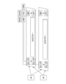
- FIG. 3 is a diagram showing the configuration of a wireless communication network according to an embodiment of the present invention.
- the wireless communication network 1 includes a virtual private network control device 10, a user database 20, a virtual private network configuration profile management device 30, an authentication/session control device 40, a network configuration information management device 50, and a transport device resource pool. 60 and a server device group 70.
- the virtual private network control device 10 communicates with a user database 20, a virtual private network configuration profile management device 30, an authentication/session control device 40, a network configuration information management device 50, a transport device resource pool 60, and a server device group 70, respectively. Possibly connected.
- Each communication method may be wireless or wired.
- the virtual private network control device 10 performs design control of specific communication functions in conjunction with C-plane control (session control) such as terminal authentication, session control, and mobility control.
- the virtual private network control device 10 also provides a network function that combines user subscription service attribute information, slice identification information, session information, access line/area information, location information, etc. with network slice function configuration conditions, network configuration information, etc. Perform design control.
- the virtual dedicated network control device 10 determines the hardware, resource amount, etc. for general-purpose devices such as server devices, accelerator devices, programmer switches, white box switches, etc. that deploy data transfer/processing logic based on the network design. do.
- the virtual private network control device 10 has a communication line configuration redesign function based on the access line/area after the movement, location information, etc. when the terminal moves in conjunction with session information, and movement or redeployment of data transfer processing logic. make it happen.
- the user database 20 stores communication service user IDs, contract service types, virtual private network identification information that provides services, communication session information, access lines, service area information, location information, etc. as data related to communication service users. do.
- the virtual private network configuration profile management device 30 stores identification information of the virtual network accommodated for each communication service, network function information deployed within the virtual private network, communication quality conditions, applicable access lines, applicable area information, and information on the virtual private network. Stores autonomous operation policy information, etc.
- the authentication/session control device 40 performs authentication of communication services with terminals on the network and control of communication sessions at the time of starting service usage.
- the network configuration information management device 50 stores physical configuration information of server devices and transport devices, physical resources (CPU (Central Processing Unit) / memory / storage / FPGA (field-programmable gate array) / GPU (Graphics Processing Unit) in each device).
- NIC Network Interface Card
- Smart NIC Smart NIC, etc.
- the transport device resource pool 60 is a group of devices that transfer data. Each transport device included in the transport device resource pool 60 is a device onto which software functions can be written.
- the transport device resource pool 60 includes a transport device control management device 61, a data transfer/processing logic repository 62, a programmable switch 63, and a white box device 64.
- the transport device control management device 61 manages the resources of the transport device resource pool, controls the allocation of data transfer and processing logic to the transport devices, and manages the status.
- the data transfer/processing logic repository 62 manages software groups deployed in programmable areas on the server device/transport device.
- the server device group 70 is a device group that performs processing such as a general-purpose server 73 and an accelerator 74. Each server device included in the server device group 70 is a device into which software functions can be written.
- the server device group 70 includes a server device control management device 71, a data transfer/processing logic repository 72, a general-purpose server 73, and an accelerator 74.
- the server device control management device 71 manages server resources included in the server device group 70, and controls data transfer and allocation of processing logic to the server devices and manages the status.
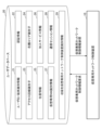
- FIG. 4 is a diagram showing an example of the functional configuration of the virtual private network control device according to the embodiment of the present invention.
- the virtual private network control device 10 includes a user data processing unit 11, a virtual private network profile processing unit 12, a communication control information processing unit 13, a physical network configuration processing unit 14, and a virtual private network design and configuration determination unit for specific communication. 15, a specific communication virtual dedicated network deployment base/resource amount determining unit 16, a communication quality/network state determination unit 17, a specific communication virtual dedicated network control instruction unit 18, a specific communication virtual dedicated network management/resource amount determination unit 16, A monitoring unit 19 is provided.
- the user data processing unit 11 processes user data stored in the user database 20. Specifically, the user data processing unit 11 acquires the user profile included in the user data from the user database 20.
- the virtual private network profile processing unit 12 acquires information indicating the attributes of the accommodation destination network stored in the virtual private network configuration profile management device 30. Specifically, the virtual private network profile processing unit 12 acquires the virtual private network configuration profile from the virtual private network type identification information.
- the communication control information processing unit 13 acquires communication control information.
- Communication control information is information for controlling communication with a terminal.
- the communication control information processing unit 13 acquires session information from the authentication/session control device 40. Session information is an example of communication control information.
- the physical network configuration processing unit 14 acquires data (information) that configures the physical network. Specifically, the physical network configuration processing unit 14 acquires physical configuration information from the network configuration information management device 50. Physical configuration information is data (information) indicating the configuration of a physical network.
- the specific communication virtual private network design/configuration determining unit 15 determines the virtual private network design/configuration for specific communication for the user. Specifically, the specific communication virtual private network design/configuration determining unit 15 designs the configuration of physical device resources corresponding to the virtual private network configuration profile.
- the specific communication virtual private network deployment base/resource amount determination unit 16 determines the base where the virtual private network is deployed and the required resource allocation amount.
- the configuration of physical device resources, the necessary resource allocation, and the like are examples of requirements that the virtual dedicated network configuration profile should satisfy (virtual dedicated network configuration profile requirements).
- the communication quality/network state determination unit 17 determines whether there is a physical device resource that satisfies the virtual dedicated network configuration profile requirements based on the communication quality and network state of the virtual dedicated network for each physical device resource.
- the specific communication virtual private network design/configuration determining unit 15, the specific communication virtual private network deployment base/resource amount determining unit 16, and the communication quality/network status determining unit 17 work together to It functions as a decision unit that decides the configuration of a virtualized network for each user.
- the specific communication virtual private network control instruction unit 18 instructs virtual private network control. Specifically, the specific communication virtual dedicated network control instruction unit 18 instructs the transfer of data transfer processing logic to the transport device control management device or server device control management device of the target base based on the design result.
- the specific communication virtual dedicated network management/monitoring unit 19 monitors the virtual dedicated network for specific communication and acquires physical device resource usage information.
- the physical device resource usage information is information indicating the usage status of the physical network.
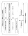
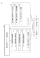
- FIG. 5 is a diagram showing an example of information stored in the user database according to the embodiment of the present invention.
- the user database 20 includes information necessary for identifying the type of virtual private network necessary for providing communication services for each communication service user, specifying application destination access, areas such as regions, and positions, and identifying communication sessions to be accommodated in the virtual private network. Memorize information, etc.
- the user database 20 includes user ID/terminal identification information 21, authentication information 22, access line identifier 23, service area identifier 24, location information 25, subscription service information 26, and virtual dedicated Network identification information 27, communication session information 28, and destination virtual dedicated network control device identification information 29 are stored.
- the user ID/terminal identification information 21 is information for uniquely identifying a user as a user ID and identifying the terminal being used.
- the authentication information 22 is information for authenticating users communicating on the network.
- the access line identifier 23 is information for identifying the access source line.
- the serving area identifier 24 is information for identifying the serving area that specifies the area to be accessed by the terminal.
- the location information 25 is information for specifying the location of the terminal.
- the subscription service information 26 is information indicating a service to which the user subscribes. The subscription service information 26 allows the virtual private network controller 10 to identify the service with which the terminal communicates.
- the virtual private network identification information 27 is information for identifying a virtual private network that provides a communication path to the subscribed service.
- Communication session information 28 is information for identifying and managing communications from terminals.
- the accommodation destination virtual private network control device identification information 29 is information for identifying the accommodation virtual private network control device 10.
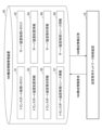
- FIG. 6 is a diagram showing an example of information stored in the virtual private network configuration profile management device according to the embodiment of the present invention.
- the virtual private network configuration profile management device 30 uses logical topology, data transfer processing logic configuration/sequence information, applicable area/access line type information, and quality conditions of the virtual private network as basic attribute values when configuring the virtual private network. , information indicating the type of hardware resource to be applied, resource design templates, etc. are stored.
- the virtual private network configuration profile management device 30 stores virtual private network type identification information 31, logical topology information 32, data transfer/processing logic configuration/sequence information 33, and applicable area/access line type information. 34, virtual private network quality conditions 35, applicable hardware resource type information 36, and resource design template 37.
- the virtual private network type identification information 31 is information for identifying the type of virtual private network to be designed and controlled.
- the logical topology information 32 is information indicating a logical network configuration.
- the data transfer/processing logic configuration/order information 33 is information indicating the configuration and application order of the data transfer/processing logic group included in the virtual private network.
- the applicable area/access line type information 34 is information used to determine areas/access lines that can be connected to the virtual private network based on location, area, and line.
- the virtual private network quality condition 35 is information indicating communication quality conditions related to services on the virtual private network.
- the applicable hardware resource type information 36 is information indicating the type of hardware resource that is applicable in the configuration of the virtual private network.
- the resource design template 37 is a template showing a typical resource deployment pattern, design, etc.
- FIG. 7 is a diagram showing an example of information stored in the network configuration information management device according to the embodiment of the present invention.
- the network configuration information management device 50 stores information indicating the physical topology, device arrangement, device type, physical resources, etc. of the transport device resource pool 60 and the server device group 70.
- the network configuration information management device 50 includes a transport physical topology 51, a server device physical topology 52, transport device placement information 53, server device placement information 54, transport device type information 55, Server device type information 56, transport device physical resource information 57, and server device physical resource information 58 are stored.
- the transport physical topology 51 is information indicating the physical connection configuration between transport devices and deployment bases.
- the server device physical topology 52 is information indicating the physical connection configuration between the server device and the deployment base.
- the transport device placement information 53 is information indicating the deployment base of each transport device included in the transport device resource pool 60.
- the server device location information 54 is information indicating the deployment base of each server device included in the server device group 70.
- the transport device type information 55 is information indicating the type of each transport device included in the transport device resource pool 60.
- the server device type information 56 is information indicating the type of each server device included in the server device group 70.
- the transport device physical resource information 57 is information indicating the type of resource included in each transport device included in the transport device resource pool 60.
- the server device physical resource information 58 is information indicating the type of resource included in each server device included in the server device group 70.
- FIG. 8 is a diagram illustrating an example of the configuration of a transport device resource pool according to an embodiment of the present invention.
- the transport device resource pool 60 includes a transport device control management device 61, a data transfer/processing logic repository 62, a programmable switch 63, and a white box device 64.
- the transport device control management device 61 includes a transport device control API function section 611, a transport device state management section 612, a transport device control management IF section 613, and a data transfer/processing logic control section 614. .
- the transport device control API function unit 611 provides an API (Application Programming Interface) for controlling the transport device.
- the transport device state management unit 612 manages the state of the transport device.
- the transport device control management IF unit 613 provides an interface for controlling the transport device.
- the data transfer/processing logic control unit 614 controls the data transfer/processing logic transferred to the transport device. Specifically, the data transfer/processing logic control unit 614 transfers the data transfer/processing logic to a transport device including the programmable switch 63, the white box device 64, etc., and activates the transferred data transfer/processing logic. After that, necessary control information is set for each session in order to set the content applied to each communication.
- the data transfer/processing logic repository 62 stores data transfer/processing logic identification information 621 and data transfer/processing logic information 622.
- the data transfer/processing logic identification information 621 is an identifier for identifying the data transfer/processing logic.
- the data transfer/processing logic information 622 is information indicating data transfer/processing logic transferred to each transport device.
- the programmable switch 63 and the white box device 64 are examples of transport devices, and may be other devices.
- FIG. 9 is a diagram illustrating an example of the configuration of a server device group according to an embodiment of the present invention.
- the server device group 70 includes a server device control management device 71, a data transfer/processing logic repository 72, a general-purpose server 73, and an accelerator 74.
- the server device control management device 71 includes a server device control API function section 711, a server device state management section 712, a server device control management IF section 713, and a data transfer/processing logic control section 714.
- the server device control API function unit 711 provides an API (Application Programming Interface) for controlling the server device.
- the server device state management unit 712 manages the state of the server device.
- the server device control management IF section 713 provides an interface for controlling the server device.
- the data transfer/processing logic control unit 714 controls data transfer/processing logic transferred to the server device. Specifically, the data transfer/processing logic control unit 714 transfers the data transfer/processing logic to a server device including the general-purpose server 73, the accelerator 74, etc., and after the transferred data transfer/processing logic is activated, Set the necessary control information for each session in order to set the content applied to each communication.
- the data transfer/processing logic repository 72 stores data transfer/processing logic identification information 721 and data transfer/processing logic information 722.
- the data transfer/processing logic identification information 721 is an identifier for identifying the data transfer/processing logic.
- the data transfer/processing logic information 722 is information indicating data transfer/processing logic to be transferred to each server device.
- the general-purpose server 73 and the accelerator 74 are examples of server devices, and may be other server devices.
- FIG. 10 is a flowchart showing an example of the flow of processing according to the embodiment of the present invention.
- the virtual private network control device 10 receives a request from a terminal and registers a user with a communication service (step S101).
- the terminal authenticates and connects to the communication network and starts communication (step S102). Subsequently, the virtual private network control device 10 acquires virtual private network information that accommodates the user from the user profile session information (step S103).
- step S103 the user data processing unit 11 acquires the user profile included in the user data from the user database 20.
- the communication control information processing unit 13 acquires session information from the authentication/session control device 40 .
- the virtual private network control device 10 acquires virtual private network information that accommodates the user from the user profile session information.
- step S104 determines whether connection to the virtual private network is permitted.
- step S104 determines that connection to the virtual private network is not permitted.
- step S104 When the virtual private network control device 10 determines that connection to the virtual private network is permitted (step S104: YES), the virtual private network profile processing unit 12 creates a virtual private network configuration profile from the virtual private network identification information. is acquired (step S105).
- the virtual private network control device 10 determines whether a virtual private network can be constructed in the user access line/area (step S106). When the virtual private network control device 10 determines that the virtual private network cannot be constructed in the user access line/area (step S106: NO), the process ends.
- step S106 determines that it is possible to construct a virtual private network in the user access line/area
- step S107 the virtual private network control device 10 acquires physical configuration information and physical device resource usage information from the network configuration information management device 50.
- step S107 the physical network configuration processing unit 14 acquires physical configuration information from the network configuration information management device 50. Further, the specific communication virtual dedicated network management/monitoring unit 19 monitors the virtual dedicated network for specific communication and acquires physical device resource usage information.
- the virtual private network control device 10 designs the configuration and allocation amount of physical device resources corresponding to the virtual private network configuration profile (step S108). Specifically, in step S108, the specific communication virtual private network design/configuration determining unit 15 designs the configuration of physical device resources corresponding to the virtual private network configuration profile. Further, the specific communication virtual private network deployment base/resource amount determination unit 16 determines the base where the virtual private network is deployed and the required resource allocation amount.
- the communication quality/network state determining unit 17 determines whether there is a physical device resource that satisfies the virtual dedicated network configuration profile requirements (step S109).
- the communication quality/network state determination unit 17 determines that there is no physical device resource that satisfies the virtual dedicated network configuration profile requirements (step S109: NO)
- the process ends.
- the specific communication virtual private network control instruction unit 18 determines the target virtual private network configuration profile based on the design result.
- the controller instructs the transport device control management device 61 or the server device control management device 71 at the base to transfer data and process logic (step S110).
- the virtual private network control device 10 loads and starts the data transfer/processing logic (step S111).
- the virtual private network control device 10 sets a transfer route between data transfer/processing logics (step S112).
- the data transfer/processing logic control unit 614 of the transport device control management device 61 or the data transfer/processing logic control unit 714 of the server device control management device 71 controls the communication flow of the user for the activated data transfer/processing logic. Parameters used in the process are set (step S113).
- the virtual private network control device 10 transfers the communication flow of the user to the activated virtual private network device (step S114).
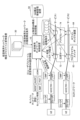
- FIG. 11 is a diagram for explaining an example in which the embodiment of the present invention is applied to a 5G network.
- the 5G network authenticates the terminal, performs session control to start communication, and establishes a communication path as a QoS flow within the 5G network. Then, in the process of establishing a QoS flow by session control of the 5G network, the corresponding session control signal is transferred to the virtual private network control device 10 (1).
- the virtual private network control device 10 acquires a user profile based on the session identifier included in the session control, and acquires information on the selection of the virtual private network of the corresponding user (2).
- the virtual private network control device 10 extracts the type of virtual private network to be set based on the information on the selection of the virtual private network, and extracts the functional configuration of the virtual private network from the virtual private network configuration profile management device 30. Information indicating conditions is acquired (3).
- the virtual private network control device 10 acquires physical network configuration information and current resource allocation information for the virtual private network from the network configuration information management device 50 (4). Next, the virtual private network control device 10 designs the data transfer/processing logic and application hardware necessary for the corresponding communication flow, and their configuration.
- the virtual private network control device 10 transfers data transfer/processing logic data to and activates the target general-purpose server 73/accelerator 74/programmable switch 63/white box device 64 according to the design (6).
- the virtual private network control device 10 sets parameters necessary to process the communication flow of the terminal in accordance with the profile conditions of the corresponding user via the transport device control management device 61 or the server device control management device 71. (7).
- the virtual private network control device 10 is realized, for example, by the hardware configuration of a computer 500 shown in FIG. 12.
- the user database 20, virtual dedicated network configuration profile management device 30, authentication/session control device 40, network configuration information management device 50, transport device control management device 61, server device control management device 71, etc. also have similar hardware configurations. It may be realized by
- the computer 500 shown in FIG. 12 includes an input device 501, a display device 502, an external I/F 503, a communication I/F 504, a processor 505, and a memory device 506. Each of these pieces of hardware is communicably connected via a bus 507.
- the input device 501 is, for example, a keyboard, a mouse, a touch panel, or the like.
- the display device 502 is, for example, a display. Note that the computer 500 does not need to have at least one of the input device 501 and the display device 502.
- the external I/F 503 is an interface with an external device such as a recording medium 503a.
- a recording medium 503a examples include a CD (Compact Disc), a DVD (Digital Versatile Disk), an SD memory card (Secure Digital memory card), and a USB (Universal Serial Bus) memory card.
- the communication I/F 504 is an interface for performing data communication with other devices, equipment, systems, etc.
- the processor 505 is, for example, various arithmetic devices such as a CPU.
- the memory device 506 is, for example, various storage devices such as an HDD, an SSD, a RAM (Random Access Memory), a ROM (Read Only Memory), and a flash memory.
- the virtual private network control device 10 can implement the various processes described above by having the hardware configuration of the computer 500 shown in FIG. 12.
- the hardware configuration of the computer 500 shown in FIG. 12 is an example, and the computer 500 may have another hardware configuration.
- computer 500 may have multiple processors 505 and multiple memory devices 506.
- the processing functions necessary for communication services are realized at the timing of starting and ending communication, and the hardware resources of the server device or the transport device are controlled by the user. Allocate data transfer/processing logic only for the necessary time while using the service. Thereby, it is possible to improve the utilization efficiency of hardware resources in the wireless communication network.
- This specification describes at least a virtual private network control device, a wireless communication system, a virtual private network control method, and a program described in the following sections.
- (Section 1) Based on data regarding users of communication services, information indicating attributes of a virtualized network for each user, information for controlling communication with the user's terminal, and information indicating the configuration of a physical network.
- a determining unit that determines a configuration of a virtualized network for each user in response to a request from the terminal; Based on the determined configuration of the virtualized network for each user, the transport device or the logic for processing is transferred to the transport device that performs data transfer or the server device that performs processing.
- a control instruction unit that instructs a device that controls the server device; Virtual private network controller.
- the determining unit determines the base where the virtualized network is deployed for each user and the necessary resource allocation as profile requirements that the virtualized network should satisfy for each user, and determines the network state or communication quality. determining a configuration of a virtualized network for each user depending on whether or not there are resources of the transport device or the server device that meet the profile requirements based on the state; The virtual private network control device according to paragraph 1. (Section 3)
- the data regarding the user of the communication service includes information for uniquely identifying the user as a user ID, identifying the terminal in use, information for authenticating the user communicating on the network, and identifying the access source line.
- the information indicating the attributes of the virtualized network for each user includes information for identifying the type of virtual private network to be designed or controlled, information indicating the logical network configuration, data transfer and Information indicating the configuration and application order of the processing logic group, information used to determine areas or access lines that can be connected to the virtual private network by location, area, or line, communication quality related to services on the virtual private network information indicating conditions, information indicating types of hardware resources that are applicable in the configuration of the virtual private network, and templates indicating typical deployment patterns or designs of the resources;
- the virtual private network control device according to paragraph 1.
- a wireless communication system comprising a virtual private network control device and a device that controls a transport device that transfers data or a server device that performs processing
- the virtual private network control device includes: Based on data regarding users of communication services, information indicating attributes of a virtualized network for each user, information for controlling communication with the user's terminal, and information indicating the configuration of a physical network.
- a determining unit that determines a configuration of a virtualized network for each user in response to a request from the terminal; Controlling the transport device or the server device to transfer data or logic for processing to the transport device or the server device based on the determined configuration of the virtualized network for each user.
- a control instruction section for instructing the device to A device that controls the transport device or the server device performs logic for the data transfer or processing in a virtualized manner for each session of the terminal, at the time of network connection of the terminal, or for each user.
- the control information required for each session is transferred when controlling the network, and the content that is applied to each communication is set after the logic for transferring or processing the transferred data is activated.
- a virtual private network control method executed by a computer the method comprising: Based on data regarding users of communication services, information indicating attributes of a virtualized network for each user, information for controlling communication with the user's terminal, and information indicating the configuration of a physical network.
- Wireless communication network 10
- Virtual private network control device 11
- User data processing unit 12
- Virtual private network profile processing unit 13
- Communication control information processing unit 14
- Physical network configuration processing unit 15
- Virtual private network design/configuration determination unit for specific communication 16
- For specific communication Virtual private network deployment base/resource amount determination unit 17
- Communication quality/network status determination unit 18
- Specific communication virtual private network control instruction unit 19
- Specific communication virtual private network management/monitoring unit 20
- User database 21 User ID/terminal identification information 22
- Authentication information 23
- Access line identifier 24
- Area area identifier 25
- Location information 26
- Subscription service information 27
- Virtual private network identification information 28
- Communication session information 29
- Host virtual private network control device identification information 30
- Virtual private network configuration profile management device 31
- Logical topology information 33
- Data transfer/processing logic configuration/sequence information 34
- Applicable area/access line type information 35
- Virtual dedicated network quality conditions 36
- Applicable hardware resource type information 37
Landscapes
- Engineering & Computer Science (AREA)
- Computer Networks & Wireless Communication (AREA)
- Signal Processing (AREA)
- Mobile Radio Communication Systems (AREA)
Abstract
通信サービスのユーザに関するデータと、前記ユーザごとに仮想化されたネットワークの属性を示す情報と、前記ユーザの端末との間の通信を制御するため情報と、物理ネットワークの構成を示す情報とに基づいて、前記端末からの要求に応じて前記ユーザごとに仮想化されたネットワークの構成を決定する決定部と、決定された前記ユーザごとに仮想化されたネットワークの構成に基づいて、データ転送を行うトランスポート装置または処理を行うサーバ装置へのデータ転送または処理のためのロジックの転送を、前記トランスポート装置または前記サーバ装置を制御する装置に指示する制御指示部と、を備える仮想専用ネットワーク制御装置である。
Description
本発明は、仮想専用ネットワーク制御装置、通信システム、仮想専用ネットワーク制御方法、及びプログラムに関する。
無線通信のリソース割当制御技術に関し、特に、ユーザの通信の発生に応じてハードウェアリソースをオンデマンドに割り当てるネットワークとセッションの制御技術が研究されている。例えば、5G無線ネットワークでは、サービスの要件に応じた仮想的なネットワーク(ネットワークスライス)技術が使用されている。
ネットワークスライスは、無線アクセス・トランスポート・コアネットワークの3つの区間において、仮想化機能、仮想ネットワークごとに分割され、互いにつなぎ合わせられた複数の物理リソースから構成される。ネットワークスライスの管理および制御は、Mプレーンで実行される。ユーザ端末毎の通信の制御は、Cプレーンで実行される。また、Uプレーンでは、端末-サービス間の通信路における品質制御、課金、サービス毎の対象サーバへのルーティングが実行される。
ところで、大容量、低遅延および低ジッタの実現、強力な暗号化処理など、通信の品質、機能等に対して、高性能化または高度化されたニーズが顕在化しつつある。これには、ソフトウェア、サーバ処理等を高性能に実現するために必要なハードウェアリソースを、ユーザの利用するサービスで必要な性能または機能に応じて柔軟に構成し割り当てる必要がある。従来のアーキテクチャでは、Mプレーンから事前にハードウェアリソースを仮想化して組み合わせ、その後Cプレーンで端末からの要求に応じて仮想化された機能において、必要な品質保証のための処理の優先順位の決定と、計算処理等を実施している(非特許文献1-非特許文献5等)。
3GPP TS28.531, "Management and orchestration; Provisioning;"
GSMA NG116, Generic Network Slice Template Version 2.0, Oct. 2019
3GPP TS28.541, "5G Network Resource Model (NRM)"
ETSI GR NFV-IFA 029, Report on the Enhancements of the NFV architecture towards "Cloud-native" and "PaaS"
3GPP TS23.501, "System architecture for the 5G System (5GS)"
従来の技術では、高性能化・高度化が進展しネットワークスライスのバリエーションが増加すると、バリエーションの数だけネットワークのハードウェアリソースを占有して、大半のリソースの利用効率が低下するという問題がある。
開示の技術は、通信ネットワークにおけるハードウェアリソースの利用効率を向上させることを目的とする。
開示の技術は、通信サービスのユーザに関するデータと、前記ユーザごとに仮想化されたネットワークの属性を示す情報と、前記ユーザの端末との間の通信を制御するため情報と、物理ネットワークの構成を示す情報とに基づいて、前記端末からの要求に応じて前記ユーザごとに仮想化されたネットワークの構成を決定する決定部と、決定された前記ユーザごとに仮想化されたネットワークの構成に基づいて、データ転送を行うトランスポート装置または処理を行うサーバ装置へのデータ転送または処理のためのロジックの転送を、前記トランスポート装置または前記サーバ装置を制御する装置に指示する制御指示部と、を備える仮想専用ネットワーク制御装置である。
通信ネットワークにおけるハードウェアリソースの利用効率を向上させることができる。
以下、図面を参照して本発明の実施の形態(本実施の形態)を説明する。以下で説明する実施の形態は一例に過ぎず、本発明が適用される実施の形態は、以下の実施の形態に限られるわけではない。
<従来の技術>
まず、従来の技術について説明する。
まず、従来の技術について説明する。
図1は、従来の無線通信ネットワークの構成について説明するための図である。5G無線ネットワークにおけるネットワークスライスは、無線アクセス・トランスポート・コアネットワークの3つの区間において、仮想化機能、仮想ネットワークごとに分割され、互いにつなぎ合わせられた複数の物理リソースから構成される。
ネットワークスライスの管理および制御は、Mプレーンで実行される。ユーザ端末毎の通信の制御は、Cプレーンで実行される。また、Uプレーンでは、端末-サービス間の通信路における品質制御、課金、サービス毎の対象サーバへのルーティングが実行される。
例えば、非特許文献1には、ネットワークオペレータによるネットワークスライスの管理・制御のための規定として、NSMS(Network Slice Management Service)/NSSMS(Network Slice Subnet Management Service)などのMプレーンの機能が開示されている。
さらに、非特許文献2および非特許文献3には、ネットワークスライスの管理または制御の単位として用いられる、NSI(Network Slice Instance)/NSSI(Network Slice Subnet Instance)と呼ばれるインスタンスとスライスプロファイル(SliceProfile)の情報について開示されている。
また、非特許文献4には、ネットワーク仮想化基盤、トランスポート基盤等のハードウェアリソースをオーケストレータ、コントローラ等から制御および設定することによって構成された、仮想化ネットワーク機能(VNF:Virtual Network Function)および仮想ネットワークを、ネットワークスライスとしてインスタンスと紐づけて管理することについて開示されている。
図2は、従来の無線通信ネットワークにおける処理の流れについて説明するための図である。Cプレーンの機能としては、CU(Centralized Unit)、5GコアネットワークにおけるAMF(Access and Mobility Management Function)、NSSF(Network Slice Selection Function)、SMF(Session Management Function)等において端末のネットワークスライスへの接続・振分、ネットワークスライス上での通信開始・終了のタイミングでの認証、QoSフローと呼ばれる通信路の制御等が実行される。
具体的には、AMFにおいて端末からの登録要求処理と連動して、NSSFにおいてユーザプロファイルのサービス条件から該当するネットワークスライスへ当該端末を収容する。次に、各サービスとの通信には、ネットワークスライス毎に配置されるSMFにより端末・サービス毎にセッションが管理され、端末毎のQoSフロー毎に品質制御・接続経路の制御情報が交換される。
また、Uプレーンの機能としては、CU-UP(Centralized Unit - User Plane)、UPF(User plane function)等においてサービス毎に必要な帯域保証などの品質の制御が実行される。
<従来の問題点>
低遅延および低ジッタの実現、強力な暗号化処理など、通信の品質、機能等に対して、高性能化または高度化されたニーズが顕在化しつつある。これには、ソフトウェア、サーバ処理等を高性能に実現するために必要なハードウェアリソースを、ユーザの利用するサービスで必要な性能または機能に応じて柔軟に構成し割り当てる必要がある。
低遅延および低ジッタの実現、強力な暗号化処理など、通信の品質、機能等に対して、高性能化または高度化されたニーズが顕在化しつつある。これには、ソフトウェア、サーバ処理等を高性能に実現するために必要なハードウェアリソースを、ユーザの利用するサービスで必要な性能または機能に応じて柔軟に構成し割り当てる必要がある。
従来のアーキテクチャでは、Mプレーンから事前にハードウェアリソースを仮想化して組み合わせ、その後Cプレーンで端末からの要求に応じて仮想化された機能において、必要な品質保証、計算処理等を実施している。
従来の技術では、高性能化・高度化が進展しネットワークスライスのバリエーションが増加すると、バリエーションの数だけネットワークのハードウェアリソースを占有して、大半のリソースの利用効率が低下するという問題がある。
<本実施の形態の概要>
本実施の形態では、上述した従来の問題点を解決するため、ユーザの通信の発生に応じてハードウェアリソースをオンデマンドに割り当てるネットワークとセッションの制御を実現させる。これによって、無線通信ネットワークにおけるハードウェアリソースの利用効率を向上させることができる。
本実施の形態では、上述した従来の問題点を解決するため、ユーザの通信の発生に応じてハードウェアリソースをオンデマンドに割り当てるネットワークとセッションの制御を実現させる。これによって、無線通信ネットワークにおけるハードウェアリソースの利用効率を向上させることができる。
<本実施の形態の全体構成>
図3は、本発明の実施の形態に係る無線通信ネットワークの構成を示す図である。無線通信ネットワーク1は、仮想専用ネットワーク制御装置10と、ユーザデータベース20と、仮想専用ネットワーク構成プロファイル管理装置30と、認証・セッション制御装置40と、ネットワーク構成情報管理装置50と、トランスポート装置リソースプール60と、サーバ装置群70と、を備える。
図3は、本発明の実施の形態に係る無線通信ネットワークの構成を示す図である。無線通信ネットワーク1は、仮想専用ネットワーク制御装置10と、ユーザデータベース20と、仮想専用ネットワーク構成プロファイル管理装置30と、認証・セッション制御装置40と、ネットワーク構成情報管理装置50と、トランスポート装置リソースプール60と、サーバ装置群70と、を備える。
仮想専用ネットワーク制御装置10は、ユーザデータベース20、仮想専用ネットワーク構成プロファイル管理装置30、認証・セッション制御装置40、ネットワーク構成情報管理装置50、トランスポート装置リソースプール60およびサーバ装置群70と、それぞれ通信可能に接続されている。それぞれの通信方法は無線でも有線でもよい。
仮想専用ネットワーク制御装置10は、端末の認証、セッション制御、移動制御などのCプレーン制御(セッション制御)と連動し特定の通信機能の設計制御を行う。また、仮想専用ネットワーク制御装置10は、ユーザの加入サービス属性情報、スライス識別情報、セッション情報、アクセス回線/エリア情報、位置情報等とネットワークスライス機能構成条件、ネットワーク構成情報等を組み合わせたネットワーク機能の設計制御を行う。
また、仮想専用ネットワーク制御装置10は、ネットワーク設計に基づくデータ転送・処理ロジックを配備するサーバ装置・アクセラレータ装置、プログラマスイッチ、ホワイトボックススイッチ等の汎用装置を対象とするハードウェア、リソース量等を決定する。さらに、仮想専用ネットワーク制御装置10は、セッション情報と連動した端末移動時の移動後のアクセス回線/エリア、位置情報等に基づく通信回線の構成再設計機能、データ転送処理ロジックの移動または再配備を実現させる。
ユーザデータベース20は、通信サービスの利用者に関するデータとして、通信サービスユーザID、契約サービス種別、サービスを提供する仮想専用ネットワーク識別情報、通信セッション情報、アクセス回線、在圏エリア情報、位置情報などを記憶する。
仮想専用ネットワーク構成プロファイル管理装置30は、通信サービス毎に収容する仮想ネットワークの識別情報、仮想専用ネットワーク内に配備するネットワーク機能情報、通信品質条件、適用対象アクセス回線、適用エリア情報、仮想専用ネットワークの自律運用ポリシ情報等を記憶する。
認証・セッション制御装置40は、ネットワーク上での端末との通信サービスの認証・サービス利用開始時の通信セッションの制御を行う。
ネットワーク構成情報管理装置50は、サーバ装置・トランスポート装置の物理構成情報、各装置内の物理リソース(CPU(Central Processing Unit)/メモリ/ストレージ/FPGA(field-programmable gate array)/GPU(Graphics Processing Unit)/NIC(Network Interface Card)/SmartNIC等)情報、各物理装置間の物理配線接続構成情報、および論理的なネットワーク機能の物理装置が有するリソースの使用状況を管理する。
トランスポート装置リソースプール60は、データ転送を行う装置群である。トランスポート装置リソースプール60に含まれる各トランスポート装置は、ソフトウェア機能を書き込み可能な装置である。
トランスポート装置リソースプール60は、トランスポート装置制御管理装置61と、データ転送・処理ロジックリポジトリ62と、プログラマブルスイッチ63と、ホワイトボックス装置64と、を備える。トランスポート装置制御管理装置61は、トランスポート装置リソースプールのリソースを管理し、トランスポート装置へのデータ転送・処理ロジックの割当の制御・状態の管理を行う。データ転送・処理ロジックリポジトリ62は、サーバ装置・トランスポート装置上のプログラマブル領域に配備するソフトウェア群を管理する。
サーバ装置群70は、汎用サーバ73、アクセラレータ74などの処理を行う装置群である。サーバ装置群70に含まれる各サーバ装置は、ソフトウェア機能を書き込み可能な装置である。サーバ装置群70は、サーバ装置制御管理装置71と、データ転送・処理ロジックリポジトリ72と、汎用サーバ73と、アクセラレータ74と、を備える。
サーバ装置制御管理装置71は、サーバ装置群70が備えるサーバリソースを管理し、サーバ装置へのデータ転送・処理ロジックの割当の制御・状態の管理を行う。
<本実施の形態に係る仮想専用ネットワーク制御装置の機能構成>
図4は、本発明の実施の形態に係る仮想専用ネットワーク制御装置の機能構成の一例を示す図である。仮想専用ネットワーク制御装置10は、ユーザデータ処理部11と、仮想専用ネットワークプロファイル処理部12と、通信制御情報処理部13と、物理ネットワーク構成処理部14と、特定通信用仮想専用ネットワーク設計・構成決定部15と、特定通信用仮想専用ネットワーク配備拠点・リソース量決定部16と、通信品質・ネットワーク状態判定部17と、特定通信用仮想専用ネットワーク制御指示部18と、特定通信用仮想専用ネットワーク管理・監視部19と、を備える。
図4は、本発明の実施の形態に係る仮想専用ネットワーク制御装置の機能構成の一例を示す図である。仮想専用ネットワーク制御装置10は、ユーザデータ処理部11と、仮想専用ネットワークプロファイル処理部12と、通信制御情報処理部13と、物理ネットワーク構成処理部14と、特定通信用仮想専用ネットワーク設計・構成決定部15と、特定通信用仮想専用ネットワーク配備拠点・リソース量決定部16と、通信品質・ネットワーク状態判定部17と、特定通信用仮想専用ネットワーク制御指示部18と、特定通信用仮想専用ネットワーク管理・監視部19と、を備える。
ユーザデータ処理部11は、ユーザデータベース20に格納されるユーザデータを処理する。具体的には、ユーザデータ処理部11は、ユーザデータに含まれるユーザプロファイルをユーザデータベース20から取得する。
仮想専用ネットワークプロファイル処理部12は、仮想専用ネットワーク構成プロファイル管理装置30が記憶する収容先のネットワークの属性を示す情報を取得する。具体的には、仮想専用ネットワークプロファイル処理部12は、仮想専用ネットワーク種別識別情報から仮想専用ネットワーク構成プロファイルを取得する。
通信制御情報処理部13は、通信制御情報を取得する。通信制御情報は、端末との間の通信を制御するための情報である。具体的には、通信制御情報処理部13は、認証・セッション制御装置40からセッション情報を取得する。セッション情報は、通信制御情報の一例である。
物理ネットワーク構成処理部14は、物理ネットワークを構成するデータ(情報)を取得する。具体的には、物理ネットワーク構成処理部14は、ネットワーク構成情報管理装置50から物理構成情報を取得する。物理構成情報は、物理ネットワークの構成を示すデータ(情報)である。
特定通信用仮想専用ネットワーク設計・構成決定部15は、当該ユーザ向けの特定通信のための仮想専用ネットワーク設計・構成を決定する。具体的には、特定通信用仮想専用ネットワーク設計・構成決定部15は、仮想専用ネットワーク構成プロファイルに対応した物理装置リソースの構成を設計する。
特定通信用仮想専用ネットワーク配備拠点・リソース量決定部16は、仮想専用ネットワークを配備する拠点および必要なリソースの割当量を決定する。物理装置リソースの構成および必要なリソースの割当量等は、仮想専用ネットワーク構成プロファイルが満たすべき要件(仮想専用ネットワーク構成プロファイル要件)の一例である。
通信品質・ネットワーク状態判定部17は、物理装置リソースごとの仮想専用ネットワークの通信品質とネットワーク状態等に基づいて、仮想専用ネットワーク構成プロファイル要件を満たす物理装置リソースがあるか否かを判定する。
特定通信用仮想専用ネットワーク設計・構成決定部15、特定通信用仮想専用ネットワーク配備拠点・リソース量決定部16および通信品質・ネットワーク状態判定部17は、協働して、端末からの要求に応じてユーザごとに仮想化されたネットワークの構成を決定する決定部として機能する。
特定通信用仮想専用ネットワーク制御指示部18は、仮想専用ネットワーク制御を指示する。具体的には、特定通信用仮想専用ネットワーク制御指示部18は、設計結果に基づき対象となる拠点のトランスポート装置制御管理装置またはサーバ装置制御管理装置へ、データ転送処理ロジックの転送を指示する。
特定通信用仮想専用ネットワーク管理・監視部19は、特定通信用の仮想専用ネットワークを監視して、物理装置リソース利用情報を取得する。物理装置リソース利用情報は、物理ネットワークの利用状況を示す情報である。
<本実施の形態に係る情報>
次に、本実施の形態に係る情報について説明する。
次に、本実施の形態に係る情報について説明する。
図5は、本発明の実施の形態に係るユーザデータベースに格納される情報の一例を示す図である。
ユーザデータベース20は、通信サービスユーザごとに通信サービスの提供に必要な仮想専用ネットワーク種別の識別、適用先アクセス、地域等のエリア、位置の特定、仮想専用ネットワークに収容する通信セッションの識別に必要な情報等を記憶する。
具体的には、ユーザデータベース20は、ユーザID/端末識別情報21と、認証情報22と、アクセス回線識別子23と、在圏エリア識別子24と、位置情報25と、加入サービス情報26と、仮想専用ネットワーク識別情報27と、通信セッション情報28と、収容先仮想専用ネットワーク制御装置識別情報29と、を記憶する。
ユーザID/端末識別情報21は、ユーザIDとしてユーザを一意に識別し、利用中の端末を識別するための情報である。認証情報22は、ネットワークにおいて通信するユーザの認証を行うための情報である。アクセス回線識別子23は、アクセス元の回線を識別するための情報である。
在圏エリア識別子24は、端末がアクセスする地域を特定する在圏エリアを識別するための情報である。位置情報25は、端末の位置を特定するための情報である。加入サービス情報26は、ユーザが加入するサービスを示す情報である。加入サービス情報26によって、仮想専用ネットワーク制御装置10は、端末の通信先のサービスを特定することができる。
仮想専用ネットワーク識別情報27は、加入サービスへの通信路を提供する仮想専用ネットワークを識別するための情報である。通信セッション情報28は、端末からの通信を識別・管理するための情報である。収容先仮想専用ネットワーク制御装置識別情報29は、収容先の仮想専用ネットワーク制御装置10を識別するための情報である。
図6は、本発明の実施の形態に係る仮想専用ネットワーク構成プロファイル管理装置に格納される情報の一例を示す図である。仮想専用ネットワーク構成プロファイル管理装置30は、仮想専用ネットワークの構成時に基本とする属性値として、論理トポロジ、データ転送処理ロジック構成・順序情報、適用可能エリア/アクセス回線種別情報、仮想専用ネットワークの品質条件、適用されるハードウェアリソースの種別を示す情報、リソース設計テンプレートなどを記憶する。
具体的には、仮想専用ネットワーク構成プロファイル管理装置30は、仮想専用ネットワーク種別識別情報31と、論理トポロジ情報32と、データ転送・処理ロジック構成・順序情報33と、適用可能エリア/アクセス回線種別情報34と、仮想専用ネットワーク品質条件35と、適用ハードウェアリソース種別情報36と、リソース設計テンプレート37と、を記憶する。
仮想専用ネットワーク種別識別情報31は、設計・制御する仮想専用ネットワークの種類を識別するための情報である。論理トポロジ情報32は、論理的なネットワーク構成を示す情報である。データ転送・処理ロジック構成・順序情報33は、仮想専用ネットワークに含まれるデータ転送・処理ロジック群の構成および適用順序を示す情報である。
適用可能エリア/アクセス回線種別情報34は、場所・エリア・回線による仮想専用ネットワークへの接続が可能なエリア/アクセス回線の判断に用いられる情報である。仮想専用ネットワーク品質条件35は、仮想専用ネットワーク上でのサービスに係る通信品質の条件を示す情報である。
適用ハードウェアリソース種別情報36は、仮想専用ネットワークの構成において適用可能とするハードウェアリソースの種別を示す情報である。リソース設計テンプレート37は、リソースの典型的な配備パターン、設計等を示すテンプレートである。
図7は、本発明の実施の形態に係るネットワーク構成情報管理装置に格納される情報の一例を示す図である。ネットワーク構成情報管理装置50は、トランスポート装置リソースプール60およびサーバ装置群70の物理トポロジ、装置配置、装置種別、物理リソース等を示す情報を記憶する。
具体的には、ネットワーク構成情報管理装置50は、トランスポート物理トポロジ51と、サーバ装置物理トポロジ52と、トランスポート装置配置情報53と、サーバ装置配置情報54と、トランスポート装置種別情報55と、サーバ装置種別情報56と、トランスポート装置物理リソース情報57と、サーバ装置物理リソース情報58と、を記憶する。
トランスポート物理トポロジ51は、トランスポート装置・配備拠点間の物理的な接続構成を示す情報である。サーバ装置物理トポロジ52は、サーバ装置・配備拠点間の物理的な接続構成を示す情報である。
トランスポート装置配置情報53は、トランスポート装置リソースプール60に含まれる各トランスポート装置の配備拠点を示す情報である。サーバ装置配置情報54は、サーバ装置群70に含まれる各サーバ装置の配備拠点を示す情報である。
トランスポート装置種別情報55は、トランスポート装置リソースプール60に含まれる各トランスポート装置の種別を示す情報である。サーバ装置種別情報56は、サーバ装置群70に含まれる各サーバ装置の種別を示す情報である。
トランスポート装置物理リソース情報57は、トランスポート装置リソースプール60に含まれる各トランスポート装置に含まれるリソースの種別を示す情報である。サーバ装置物理リソース情報58は、サーバ装置群70に含まれる各サーバ装置に含まれるリソースの種別を示す情報である。
<本実施の形態に係る仮想専用ネットワーク装置>
次に、本実施の形態に係る仮想専用ネットワーク装置について説明する。
次に、本実施の形態に係る仮想専用ネットワーク装置について説明する。
図8は、本発明の実施の形態に係るトランスポート装置リソースプールの構成の一例を示す図である。トランスポート装置リソースプール60は、トランスポート装置制御管理装置61と、データ転送・処理ロジックリポジトリ62と、プログラマブルスイッチ63と、ホワイトボックス装置64と、を備える。
トランスポート装置制御管理装置61は、トランスポート装置制御API機能部611と、トランスポート装置状態管理部612と、トランスポート装置制御管理IF部613と、データ転送・処理ロジック制御部614と、を備える。
トランスポート装置制御API機能部611は、トランスポート装置を制御するためのAPI(Application Programming Interface)を提供する。トランスポート装置状態管理部612は、トランスポート装置の状態を管理する。トランスポート装置制御管理IF部613は、トランスポート装置を制御するためのインタフェースを提供する。
データ転送・処理ロジック制御部614は、トランスポート装置に転送されたデータ転送・処理ロジックを制御する。具体的には、データ転送・処理ロジック制御部614は、プログラマブルスイッチ63、ホワイトボックス装置64等を含むトランスポート装置にデータ転送・処理ロジックを転送し、転送されたデータ転送・処理ロジックが起動された後に、個々の通信に対して適用される内容を設定するため、セッションごとに必要な制御情報を設定する。
データ転送・処理ロジックリポジトリ62は、データ転送・処理ロジック識別情報621と、データ転送・処理ロジック情報622と、を記憶する。
データ転送・処理ロジック識別情報621は、データ転送・処理ロジックを識別するための識別子である。データ転送・処理ロジック情報622は、各トランスポート装置に転送されるデータ転送・処理ロジックを示す情報である。
プログラマブルスイッチ63およびホワイトボックス装置64は、トランスポート装置の一例であって、他でもよい。
図9は、本発明の実施の形態に係るサーバ装置群の構成の一例を示す図である。サーバ装置群70は、サーバ装置制御管理装置71と、データ転送・処理ロジックリポジトリ72と、汎用サーバ73と、アクセラレータ74と、を備える。
サーバ装置制御管理装置71は、サーバ装置制御API機能部711と、サーバ装置状態管理部712と、サーバ装置制御管理IF部713と、データ転送・処理ロジック制御部714と、を備える。
サーバ装置制御API機能部711は、サーバ装置を制御するためのAPI(Application Programming Interface)を提供する。サーバ装置状態管理部712は、サーバ装置の状態を管理する。サーバ装置制御管理IF部713は、サーバ装置を制御するためのインタフェースを提供する。
データ転送・処理ロジック制御部714は、サーバ装置に転送されたデータ転送・処理ロジックを制御する。具体的には、データ転送・処理ロジック制御部714は、汎用サーバ73、アクセラレータ74等を含むサーバ装置にデータ転送・処理ロジックを転送し、転送されたデータ転送・処理ロジックが起動された後に、個々の通信に対して適用される内容を設定するため、セッションごとに必要な制御情報を設定する。
データ転送・処理ロジックリポジトリ72は、データ転送・処理ロジック識別情報721と、データ転送・処理ロジック情報722と、を記憶する。
データ転送・処理ロジック識別情報721は、データ転送・処理ロジックを識別するための識別子である。データ転送・処理ロジック情報722は、各サーバ装置に転送されるデータ転送・処理ロジックを示す情報である。
汎用サーバ73およびアクセラレータ74は、サーバ装置の一例であって、他でもよい。
<本実施の形態に係る動作>
図10は、本発明の実施の形態に係る処理の流れの一例を示すフローチャートである。仮想専用ネットワーク制御装置10は、端末からの要求を受けて、ユーザを通信サービスに登録する(ステップS101)。
図10は、本発明の実施の形態に係る処理の流れの一例を示すフローチャートである。仮想専用ネットワーク制御装置10は、端末からの要求を受けて、ユーザを通信サービスに登録する(ステップS101)。
端末は、通信ネットワークへ認証・接続し通信を開始する(ステップS102)。続いて、仮想専用ネットワーク制御装置10は、ユーザプロファイル・セッション情報から当該ユーザの収容先となる仮想専用ネットワーク情報を取得する(ステップS103)。
ステップS103において、具体的には、ユーザデータ処理部11は、ユーザデータに含まれるユーザプロファイルをユーザデータベース20から取得する。通信制御情報処理部13は、認証・セッション制御装置40からセッション情報を取得する。これによって、仮想専用ネットワーク制御装置10は、ユーザプロファイル・セッション情報から当該ユーザの収容先となる仮想専用ネットワーク情報を取得する。
次に、仮想専用ネットワーク制御装置10は、当該仮想専用ネットワークへの接続が許可されているか否かを判定する(ステップS104)。仮想専用ネットワーク制御装置10は、当該仮想専用ネットワークへの接続が許可されていないと判定すると(ステップS104:NO)、処理を終了する。
仮想専用ネットワーク制御装置10が、当該仮想専用ネットワークへの接続が許可されていると判定すると(ステップS104:YES)、仮想専用ネットワークプロファイル処理部12は、仮想専用ネットワーク識別情報から仮想専用ネットワーク構成プロファイルを取得する(ステップS105)。
続いて、仮想専用ネットワーク制御装置10は、ユーザアクセス回線/エリアで仮想専用ネットワーク構築が可能か否かを判定する(ステップS106)。仮想専用ネットワーク制御装置10は、ユーザアクセス回線/エリアで仮想専用ネットワーク構築ができないと判定すると(ステップS106:NO)、処理を終了する。
仮想専用ネットワーク制御装置10は、ユーザアクセス回線/エリアで仮想専用ネットワーク構築が可能であると判定すると(ステップS106:YES)、ネットワーク構成情報管理装置50から物理構成情報および物理装置リソース利用情報を取得する(ステップS107)。
具体的には、ステップS107において、物理ネットワーク構成処理部14は、ネットワーク構成情報管理装置50から物理構成情報を取得する。また、特定通信用仮想専用ネットワーク管理・監視部19は、特定通信用の仮想専用ネットワークを監視して、物理装置リソース利用情報を取得する。
次に、仮想専用ネットワーク制御装置10は、仮想専用ネットワーク構成プロファイルに対応した物理装置リソースの構成・割当量を設計する(ステップS108)。具体的には、ステップS108において、特定通信用仮想専用ネットワーク設計・構成決定部15は、仮想専用ネットワーク構成プロファイルに対応した物理装置リソースの構成を設計する。また、特定通信用仮想専用ネットワーク配備拠点・リソース量決定部16は、仮想専用ネットワークを配備する拠点および必要なリソースの割当量を決定する。
続いて、通信品質・ネットワーク状態判定部17は、仮想専用ネットワーク構成プロファイル要件を満たす物理装置リソースがあるか否かを判定する(ステップS109)。通信品質・ネットワーク状態判定部17は、仮想専用ネットワーク構成プロファイル要件を満たす物理装置リソースがないと判定すると(ステップS109:NO)、処理を終了する。
通信品質・ネットワーク状態判定部17が、仮想専用ネットワーク構成プロファイル要件を満たす物理装置リソースがあると判定すると(ステップS109:YES)、特定通信用仮想専用ネットワーク制御指示部18は、設計結果に基づき対象となる拠点のトランスポート装置制御管理装置61またはサーバ装置制御管理装置71へデータ転送・処理ロジックの転送を指示する(ステップS110)。
続いて、仮想専用ネットワーク制御装置10は、トランスポート装置制御管理装置61またはサーバ装置制御管理装置71は、データ転送・処理ロジックをロードし起動する(ステップS111)。仮想専用ネットワーク制御装置10は、データ転送・処理ロジック間の転送経路を設定する(ステップS112)。
トランスポート装置制御管理装置61のデータ転送・処理ロジック制御部614またはサーバ装置制御管理装置71のデータ転送・処理ロジック制御部714は、起動したデータ転送・処理ロジックに対して当該ユーザの通信フローの処理で用いるパラメータを設定する(ステップS113)。仮想専用ネットワーク制御装置10は、当該ユーザの通信フローを起動した仮想専用ネットワーク装置へ転送する(ステップS114)。
<本実施の形態の実施例>
図11は、本発明の実施の形態を5Gネットワークに適用した実施例について説明するための図である。5Gネットワークは、端末を認証し、通信を開始するためセッション制御を行って、5Gネットワーク内にQoSフローとして通信路を確立する。そして、5Gネットワークのセッション制御によるQoSフロー確立過程において、仮想専用ネットワーク制御装置10に該当のセッション制御信号を転送する(1)。
図11は、本発明の実施の形態を5Gネットワークに適用した実施例について説明するための図である。5Gネットワークは、端末を認証し、通信を開始するためセッション制御を行って、5Gネットワーク内にQoSフローとして通信路を確立する。そして、5Gネットワークのセッション制御によるQoSフロー確立過程において、仮想専用ネットワーク制御装置10に該当のセッション制御信号を転送する(1)。
続いて、仮想専用ネットワーク制御装置10は、セッション制御に含まれるセッション識別子によりユーザプロファイルを取得し、該当ユーザの仮想専用ネットワークを選択した情報を取得する(2)。
そして、仮想専用ネットワーク制御装置10は、仮想専用ネットワークを選択した情報に基づいて、設定対象とする仮想専用ネットワークの種別を抽出し、仮想専用ネットワーク構成プロファイル管理装置30から仮想専用ネットワークの機能構成の条件を示す情報を取得する(3)。
仮想専用ネットワーク制御装置10は、ネットワーク構成情報管理装置50から物理ネットワーク構成情報・現在の仮想専用ネットワークへのリソース割当情報を取得する(4)。続いて、仮想専用ネットワーク制御装置10は、該当の通信フローに必要となるデータ転送・処理ロジックと適用先ハードウェア、およびそれらの構成を設計する。
仮想専用ネットワーク制御装置10は、設計に従い対象となる汎用サーバ73/アクセラレータ74/プログラマブルスイッチ63/ホワイトボックス装置64に対して、データ転送・処理ロジックデータを転送し起動する(6)。仮想専用ネットワーク制御装置10は、トランスポート装置制御管理装置61またはサーバ装置制御管理装置71を介して、該当のユーザのプロファイル条件に沿って端末の通信フローを処理するために必要なパラメータ設定を行う(7)。
このようにして、5GネットワークのUPFと、データ転送・処理ロジックに従った処理を実行している仮想専用ネットワーク装置(トランスポート装置またはサーバ装置)との間でデータ転送処理が実行され、サービスへの通信フローが確立する。
<ハードウェア構成>
最後に、本実施形態に係る仮想専用ネットワーク制御装置10のハードウェア構成について説明する。本実施形態に係る仮想専用ネットワーク制御装置10は、例えば、図12に示すコンピュータ500のハードウェア構成により実現される。なお、ユーザデータベース20、仮想専用ネットワーク構成プロファイル管理装置30、認証・セッション制御装置40、ネットワーク構成情報管理装置50、トランスポート装置制御管理装置61、サーバ装置制御管理装置71等も同様のハードウェア構成で実現されていてもよい。
最後に、本実施形態に係る仮想専用ネットワーク制御装置10のハードウェア構成について説明する。本実施形態に係る仮想専用ネットワーク制御装置10は、例えば、図12に示すコンピュータ500のハードウェア構成により実現される。なお、ユーザデータベース20、仮想専用ネットワーク構成プロファイル管理装置30、認証・セッション制御装置40、ネットワーク構成情報管理装置50、トランスポート装置制御管理装置61、サーバ装置制御管理装置71等も同様のハードウェア構成で実現されていてもよい。
図12に示すコンピュータ500は、入力装置501と、表示装置502と、外部I/F503と、通信I/F504と、プロセッサ505と、メモリ装置506とを有する。これらの各ハードウェアは、それぞれがバス507により通信可能に接続される。
入力装置501は、例えば、キーボードやマウス、タッチパネル等である。表示装置502は、例えば、ディスプレイ等である。なお、コンピュータ500は、入力装置501及び表示装置502のうちの少なくとも一方を有していなくてもよい。
外部I/F503は、記録媒体503a等の外部装置とのインタフェースである。なお、記録媒体503aとしては、例えば、CD(Compact Disc)、DVD(Digital Versatile Disk)、SDメモリカード(Secure Digital memory card)、USB(Universal Serial Bus)メモリカード等が挙げられる。
通信I/F504は、他の装置や機器、システム等との間でデータ通信を行うためのインタフェースである。プロセッサ505は、例えば、CPU等の各種演算装置である。メモリ装置506は、例えば、HDDやSSD、RAM(Random Access Memory)、ROM(Read Only Memory)、フラッシュメモリ等の各種記憶装置である。
本実施形態に係る仮想専用ネットワーク制御装置10は、図12に示すコンピュータ500のハードウェア構成を有することにより、上述した各種処理を実現することができる。なお、図12に示すコンピュータ500のハードウェア構成は一例であって、コンピュータ500は、他のハードウェア構成を有していてもよい。例えば、コンピュータ500は、複数のプロセッサ505を有していてもよいし、複数のメモリ装置506を有していてもよい。
本実施の形態に係る仮想専用ネットワーク制御装置10によれば、通信の開始・終了のタイミングで通信サービスに必要な処理機能を実現させ、サーバ装置またはトランスポート装置のハードウェアリソースに対し、ユーザのサービス利用中の必要な時間だけデータ転送・処理ロジックを割り当てる。これによって、無線通信ネットワークにおけるハードウェアリソースの利用効率を向上させることができる。
(実施の形態のまとめ)
本明細書には、少なくとも下記の各項に記載した仮想専用ネットワーク制御装置、無線通信システム、仮想専用ネットワーク制御方法、及びプログラムが記載されている。
(第1項)
通信サービスのユーザに関するデータと、前記ユーザごとに仮想化されたネットワークの属性を示す情報と、前記ユーザの端末との間の通信を制御するため情報と、物理ネットワークの構成を示す情報とに基づいて、前記端末からの要求に応じて前記ユーザごとに仮想化されたネットワークの構成を決定する決定部と、
決定された前記ユーザごとに仮想化されたネットワークの構成に基づいて、データ転送を行うトランスポート装置または処理を行うサーバ装置へのデータ転送または処理のためのロジックの転送を、前記トランスポート装置または前記サーバ装置を制御する装置に指示する制御指示部と、を備える、
仮想専用ネットワーク制御装置。
(第2項)
前記決定部は、前記ユーザごとに仮想化されたネットワークを配備する拠点および必要なリソースの割当量を前記ユーザごとに仮想化されたネットワークが満たすべきプロファイル要件として決定し、ネットワーク状態または通信品質の状態に基づいて、前記プロファイル要件を満たす前記トランスポート装置または前記サーバ装置のリソースがあるか否かに応じて、前記ユーザごとに仮想化されたネットワークの構成を決定する、
第1項に記載の仮想専用ネットワーク制御装置。
(第3項)
前記通信サービスのユーザに関するデータは、ユーザIDとしてユーザを一意に識別し、利用中の端末を識別するための情報、ネットワークにおいて通信するユーザの認証を行うための情報、アクセス元の回線を識別するための情報、端末がアクセスする地域を特定する在圏エリアを識別するための情報、端末の位置を特定するための情報、ユーザが加入するサービスを示す情報、加入サービスへの通信路を提供する仮想専用ネットワークを識別するための情報、および端末からの通信を識別または管理するための情報のいずれかを含む、
第1項に記載の仮想専用ネットワーク制御装置。
(第4項)
前記ユーザごとに仮想化されたネットワークの属性を示す情報は、設計または制御する仮想専用ネットワークの種類を識別するための情報、論理的なネットワーク構成を示す情報、仮想専用ネットワークに含まれるデータ転送・処理ロジック群の構成および適用順序を示す情報、場所、エリアまたは回線による仮想専用ネットワークへの接続が可能なエリアまたはアクセス回線の判断に用いられる情報、仮想専用ネットワーク上でのサービスに係る通信品質の条件を示す情報、仮想専用ネットワークの構成において適用可能とするハードウェアリソースの種別を示す情報、およびリソースの典型的な配備パターンまたは設計を示すテンプレートのいずれかを含む、
第1項に記載の仮想専用ネットワーク制御装置。
(第5項)
仮想専用ネットワーク制御装置と、データ転送を行うトランスポート装置または処理を行うサーバ装置を制御する装置と、を備える無線通信システムであって、
前記仮想専用ネットワーク制御装置は、
通信サービスのユーザに関するデータと、前記ユーザごとに仮想化されたネットワークの属性を示す情報と、前記ユーザの端末との間の通信を制御するため情報と、物理ネットワークの構成を示す情報とに基づいて、前記端末からの要求に応じて前記ユーザごとに仮想化されたネットワークの構成を決定する決定部と、
決定された前記ユーザごとに仮想化されたネットワークの構成に基づいて、前記トランスポート装置または前記サーバ装置へのデータ転送または処理のためのロジックの転送を、前記トランスポート装置または前記サーバ装置を制御する装置に指示する制御指示部と、を備え、
前記トランスポート装置または前記サーバ装置を制御する装置は、前記データ転送または処理のためのロジックを、前記端末のセッションごとに、前記端末のネットワーク接続の際に、または前記ユーザごとに仮想化されたネットワークの制御の際に転送し、転送された前記データ転送または処理のためのロジックが起動された後に、個々の通信に対して適用される内容を設定するため、セッションごとに必要な制御情報を設定するロジック制御部を備える、
無線通信システム。
(第6項)
コンピュータが実行する仮想専用ネットワーク制御方法であって、
通信サービスのユーザに関するデータと、前記ユーザごとに仮想化されたネットワークの属性を示す情報と、前記ユーザの端末との間の通信を制御するため情報と、物理ネットワークの構成を示す情報とに基づいて、前記端末からの要求に応じて前記ユーザごとに仮想化されたネットワークの構成を決定するステップと、
決定された前記ユーザごとに仮想化されたネットワークの構成に基づいて、データ転送を行うトランスポート装置または処理を行うサーバ装置へのデータ転送または処理のためのロジックの転送を、前記トランスポート装置または前記サーバ装置を制御する装置に指示するステップと、を備える、
仮想専用ネットワーク制御方法。
(第7項)
コンピュータを、第1項から第4項のいずれか1項に記載の仮想専用ネットワーク制御装置における各部として機能させるためのプログラム。
本明細書には、少なくとも下記の各項に記載した仮想専用ネットワーク制御装置、無線通信システム、仮想専用ネットワーク制御方法、及びプログラムが記載されている。
(第1項)
通信サービスのユーザに関するデータと、前記ユーザごとに仮想化されたネットワークの属性を示す情報と、前記ユーザの端末との間の通信を制御するため情報と、物理ネットワークの構成を示す情報とに基づいて、前記端末からの要求に応じて前記ユーザごとに仮想化されたネットワークの構成を決定する決定部と、
決定された前記ユーザごとに仮想化されたネットワークの構成に基づいて、データ転送を行うトランスポート装置または処理を行うサーバ装置へのデータ転送または処理のためのロジックの転送を、前記トランスポート装置または前記サーバ装置を制御する装置に指示する制御指示部と、を備える、
仮想専用ネットワーク制御装置。
(第2項)
前記決定部は、前記ユーザごとに仮想化されたネットワークを配備する拠点および必要なリソースの割当量を前記ユーザごとに仮想化されたネットワークが満たすべきプロファイル要件として決定し、ネットワーク状態または通信品質の状態に基づいて、前記プロファイル要件を満たす前記トランスポート装置または前記サーバ装置のリソースがあるか否かに応じて、前記ユーザごとに仮想化されたネットワークの構成を決定する、
第1項に記載の仮想専用ネットワーク制御装置。
(第3項)
前記通信サービスのユーザに関するデータは、ユーザIDとしてユーザを一意に識別し、利用中の端末を識別するための情報、ネットワークにおいて通信するユーザの認証を行うための情報、アクセス元の回線を識別するための情報、端末がアクセスする地域を特定する在圏エリアを識別するための情報、端末の位置を特定するための情報、ユーザが加入するサービスを示す情報、加入サービスへの通信路を提供する仮想専用ネットワークを識別するための情報、および端末からの通信を識別または管理するための情報のいずれかを含む、
第1項に記載の仮想専用ネットワーク制御装置。
(第4項)
前記ユーザごとに仮想化されたネットワークの属性を示す情報は、設計または制御する仮想専用ネットワークの種類を識別するための情報、論理的なネットワーク構成を示す情報、仮想専用ネットワークに含まれるデータ転送・処理ロジック群の構成および適用順序を示す情報、場所、エリアまたは回線による仮想専用ネットワークへの接続が可能なエリアまたはアクセス回線の判断に用いられる情報、仮想専用ネットワーク上でのサービスに係る通信品質の条件を示す情報、仮想専用ネットワークの構成において適用可能とするハードウェアリソースの種別を示す情報、およびリソースの典型的な配備パターンまたは設計を示すテンプレートのいずれかを含む、
第1項に記載の仮想専用ネットワーク制御装置。
(第5項)
仮想専用ネットワーク制御装置と、データ転送を行うトランスポート装置または処理を行うサーバ装置を制御する装置と、を備える無線通信システムであって、
前記仮想専用ネットワーク制御装置は、
通信サービスのユーザに関するデータと、前記ユーザごとに仮想化されたネットワークの属性を示す情報と、前記ユーザの端末との間の通信を制御するため情報と、物理ネットワークの構成を示す情報とに基づいて、前記端末からの要求に応じて前記ユーザごとに仮想化されたネットワークの構成を決定する決定部と、
決定された前記ユーザごとに仮想化されたネットワークの構成に基づいて、前記トランスポート装置または前記サーバ装置へのデータ転送または処理のためのロジックの転送を、前記トランスポート装置または前記サーバ装置を制御する装置に指示する制御指示部と、を備え、
前記トランスポート装置または前記サーバ装置を制御する装置は、前記データ転送または処理のためのロジックを、前記端末のセッションごとに、前記端末のネットワーク接続の際に、または前記ユーザごとに仮想化されたネットワークの制御の際に転送し、転送された前記データ転送または処理のためのロジックが起動された後に、個々の通信に対して適用される内容を設定するため、セッションごとに必要な制御情報を設定するロジック制御部を備える、
無線通信システム。
(第6項)
コンピュータが実行する仮想専用ネットワーク制御方法であって、
通信サービスのユーザに関するデータと、前記ユーザごとに仮想化されたネットワークの属性を示す情報と、前記ユーザの端末との間の通信を制御するため情報と、物理ネットワークの構成を示す情報とに基づいて、前記端末からの要求に応じて前記ユーザごとに仮想化されたネットワークの構成を決定するステップと、
決定された前記ユーザごとに仮想化されたネットワークの構成に基づいて、データ転送を行うトランスポート装置または処理を行うサーバ装置へのデータ転送または処理のためのロジックの転送を、前記トランスポート装置または前記サーバ装置を制御する装置に指示するステップと、を備える、
仮想専用ネットワーク制御方法。
(第7項)
コンピュータを、第1項から第4項のいずれか1項に記載の仮想専用ネットワーク制御装置における各部として機能させるためのプログラム。
以上、本実施の形態について説明したが、本発明はかかる特定の実施形態に限定されるものではなく、請求の範囲に記載された本発明の要旨の範囲内において、種々の変形・変更が可能である。
1 無線通信ネットワーク
10 仮想専用ネットワーク制御装置
11 ユーザデータ処理部
12 仮想専用ネットワークプロファイル処理部
13 通信制御情報処理部
14 物理ネットワーク構成処理部
15 特定通信用仮想専用ネットワーク設計・構成決定部
16 特定通信用仮想専用ネットワーク配備拠点・リソース量決定部
17 通信品質・ネットワーク状態判定部
18 特定通信用仮想専用ネットワーク制御指示部
19 特定通信用仮想専用ネットワーク管理・監視部
20 ユーザデータベース
21 ユーザID/端末識別情報
22 認証情報
23 アクセス回線識別子
24 在圏エリア識別子
25 位置情報
26 加入サービス情報
27 仮想専用ネットワーク識別情報
28 通信セッション情報
29 収容先仮想専用ネットワーク制御装置識別情報
30 仮想専用ネットワーク構成プロファイル管理装置
31 仮想専用ネットワーク種別識別情報
32 論理トポロジ情報
33 データ転送・処理ロジック構成・順序情報
34 適用可能エリア/アクセス回線種別情報
35 仮想専用ネットワーク品質条件
36 適用ハードウェアリソース種別情報
37 リソース設計テンプレート
40 認証・セッション制御装置
50 ネットワーク構成情報管理装置
51 トランスポート物理トポロジ
52 サーバ装置物理トポロジ
53 トランスポート装置配置情報
54 サーバ装置配置情報
55 トランスポート装置種別情報
56 サーバ装置種別情報
57 トランスポート装置物理リソース情報
58 サーバ装置物理リソース情報
60 トランスポート装置リソースプール
61 トランスポート装置制御管理装置
611 トランスポート装置制御API機能部
612 トランスポート装置状態管理部
613 トランスポート装置制御管理IF部
614 データ転送・処理ロジック制御部
62 データ転送・処理ロジックリポジトリ
621 データ転送・処理ロジック識別情報
622 データ転送・処理ロジック情報
63 プログラマブルスイッチ
64 ホワイトボックス装置
70 サーバ装置群
71 サーバ装置制御管理装置
711 サーバ装置制御API機能部
712 サーバ装置状態管理部
713 サーバ装置制御管理IF部
714 データ転送・処理ロジック制御部
72 データ転送・処理ロジックリポジトリ
721 データ転送・処理ロジック識別情報
722 データ転送・処理ロジック情報
73 汎用サーバ
74 アクセラレータ
500 コンピュータ
501 入力装置
502 表示装置
503 外部I/F
503a 記録媒体
504 通信I/F
505 プロセッサ
506 メモリ装置
507 バス
10 仮想専用ネットワーク制御装置
11 ユーザデータ処理部
12 仮想専用ネットワークプロファイル処理部
13 通信制御情報処理部
14 物理ネットワーク構成処理部
15 特定通信用仮想専用ネットワーク設計・構成決定部
16 特定通信用仮想専用ネットワーク配備拠点・リソース量決定部
17 通信品質・ネットワーク状態判定部
18 特定通信用仮想専用ネットワーク制御指示部
19 特定通信用仮想専用ネットワーク管理・監視部
20 ユーザデータベース
21 ユーザID/端末識別情報
22 認証情報
23 アクセス回線識別子
24 在圏エリア識別子
25 位置情報
26 加入サービス情報
27 仮想専用ネットワーク識別情報
28 通信セッション情報
29 収容先仮想専用ネットワーク制御装置識別情報
30 仮想専用ネットワーク構成プロファイル管理装置
31 仮想専用ネットワーク種別識別情報
32 論理トポロジ情報
33 データ転送・処理ロジック構成・順序情報
34 適用可能エリア/アクセス回線種別情報
35 仮想専用ネットワーク品質条件
36 適用ハードウェアリソース種別情報
37 リソース設計テンプレート
40 認証・セッション制御装置
50 ネットワーク構成情報管理装置
51 トランスポート物理トポロジ
52 サーバ装置物理トポロジ
53 トランスポート装置配置情報
54 サーバ装置配置情報
55 トランスポート装置種別情報
56 サーバ装置種別情報
57 トランスポート装置物理リソース情報
58 サーバ装置物理リソース情報
60 トランスポート装置リソースプール
61 トランスポート装置制御管理装置
611 トランスポート装置制御API機能部
612 トランスポート装置状態管理部
613 トランスポート装置制御管理IF部
614 データ転送・処理ロジック制御部
62 データ転送・処理ロジックリポジトリ
621 データ転送・処理ロジック識別情報
622 データ転送・処理ロジック情報
63 プログラマブルスイッチ
64 ホワイトボックス装置
70 サーバ装置群
71 サーバ装置制御管理装置
711 サーバ装置制御API機能部
712 サーバ装置状態管理部
713 サーバ装置制御管理IF部
714 データ転送・処理ロジック制御部
72 データ転送・処理ロジックリポジトリ
721 データ転送・処理ロジック識別情報
722 データ転送・処理ロジック情報
73 汎用サーバ
74 アクセラレータ
500 コンピュータ
501 入力装置
502 表示装置
503 外部I/F
503a 記録媒体
504 通信I/F
505 プロセッサ
506 メモリ装置
507 バス
Claims (7)
- 通信サービスのユーザに関するデータと、前記ユーザごとに仮想化されたネットワークの属性を示す情報と、前記ユーザの端末との間の通信を制御するため情報と、物理ネットワークの構成を示す情報とに基づいて、前記端末からの要求に応じて前記ユーザごとに仮想化されたネットワークの構成を決定する決定部と、
決定された前記ユーザごとに仮想化されたネットワークの構成に基づいて、データ転送を行うトランスポート装置または処理を行うサーバ装置へのデータ転送または処理のためのロジックの転送を、前記トランスポート装置または前記サーバ装置を制御する装置に指示する制御指示部と、を備える、
仮想専用ネットワーク制御装置。 - 前記決定部は、前記ユーザごとに仮想化されたネットワークを配備する拠点および必要なリソースの割当量を前記ユーザごとに仮想化されたネットワークが満たすべきプロファイル要件として決定し、ネットワーク状態または通信品質の状態に基づいて、前記プロファイル要件を満たす前記トランスポート装置または前記サーバ装置のリソースがあるか否かに応じて、前記ユーザごとに仮想化されたネットワークの構成を決定する、
請求項1に記載の仮想専用ネットワーク制御装置。 - 前記通信サービスのユーザに関するデータは、ユーザIDとしてユーザを一意に識別し、利用中の端末を識別するための情報、ネットワークにおいて通信するユーザの認証を行うための情報、アクセス元の回線を識別するための情報、端末がアクセスする地域を特定する在圏エリアを識別するための情報、端末の位置を特定するための情報、ユーザが加入するサービスを示す情報、加入サービスへの通信路を提供する仮想専用ネットワークを識別するための情報、および端末からの通信を識別または管理するための情報のいずれかを含む、
請求項1に記載の仮想専用ネットワーク制御装置。 - 前記ユーザごとに仮想化されたネットワークの属性を示す情報は、設計または制御する仮想専用ネットワークの種類を識別するための情報、論理的なネットワーク構成を示す情報、仮想専用ネットワークに含まれるデータ転送・処理ロジック群の構成および適用順序を示す情報、場所、エリアまたは回線による仮想専用ネットワークへの接続が可能なエリアまたはアクセス回線の判断に用いられる情報、仮想専用ネットワーク上でのサービスに係る通信品質の条件を示す情報、仮想専用ネットワークの構成において適用可能とするハードウェアリソースの種別を示す情報、およびリソースの典型的な配備パターンまたは設計を示すテンプレートのいずれかを含む、
請求項1に記載の仮想専用ネットワーク制御装置。 - 仮想専用ネットワーク制御装置と、データ転送を行うトランスポート装置または処理を行うサーバ装置を制御する装置と、を備える無線通信システムであって、
前記仮想専用ネットワーク制御装置は、
通信サービスのユーザに関するデータと、前記ユーザごとに仮想化されたネットワークの属性を示す情報と、前記ユーザの端末との間の通信を制御するため情報と、物理ネットワークの構成を示す情報とに基づいて、前記端末からの要求に応じて前記ユーザごとに仮想化されたネットワークの構成を決定する決定部と、
決定された前記ユーザごとに仮想化されたネットワークの構成に基づいて、前記トランスポート装置または前記サーバ装置へのデータ転送または処理のためのロジックの転送を、前記トランスポート装置または前記サーバ装置を制御する装置に指示する制御指示部と、を備え、
前記トランスポート装置または前記サーバ装置を制御する装置は、前記データ転送または処理のためのロジックを、前記端末のセッションごとに、前記端末のネットワーク接続の際に、または前記ユーザごとに仮想化されたネットワークの制御の際に転送し、転送された前記データ転送または処理のためのロジックが起動された後に、個々の通信に対して適用される内容を設定するため、セッションごとに必要な制御情報を設定するロジック制御部を備える、
無線通信システム。 - コンピュータが実行する仮想専用ネットワーク制御方法であって、
通信サービスのユーザに関するデータと、前記ユーザごとに仮想化されたネットワークの属性を示す情報と、前記ユーザの端末との間の通信を制御するため情報と、物理ネットワークの構成を示す情報とに基づいて、前記端末からの要求に応じて前記ユーザごとに仮想化されたネットワークの構成を決定するステップと、
決定された前記ユーザごとに仮想化されたネットワークの構成に基づいて、データ転送を行うトランスポート装置または処理を行うサーバ装置へのデータ転送または処理のためのロジックの転送を、前記トランスポート装置または前記サーバ装置を制御する装置に指示するステップと、を備える、
仮想専用ネットワーク制御方法。 - コンピュータを、請求項1から4のいずれか1項に記載の仮想専用ネットワーク制御装置における各部として機能させるためのプログラム。
Priority Applications (2)
| Application Number | Priority Date | Filing Date | Title |
|---|---|---|---|
| JP2024528126A JP7810261B2 (ja) | 2022-06-20 | 2022-06-20 | 仮想専用ネットワーク制御装置、無線通信システム、仮想専用ネットワーク制御方法、及びプログラム |
| PCT/JP2022/024619 WO2023248317A1 (ja) | 2022-06-20 | 2022-06-20 | 仮想専用ネットワーク制御装置、通信システム、仮想専用ネットワーク制御方法、及びプログラム |
Applications Claiming Priority (1)
| Application Number | Priority Date | Filing Date | Title |
|---|---|---|---|
| PCT/JP2022/024619 WO2023248317A1 (ja) | 2022-06-20 | 2022-06-20 | 仮想専用ネットワーク制御装置、通信システム、仮想専用ネットワーク制御方法、及びプログラム |
Publications (1)
| Publication Number | Publication Date |
|---|---|
| WO2023248317A1 true WO2023248317A1 (ja) | 2023-12-28 |
Family
ID=89379539
Family Applications (1)
| Application Number | Title | Priority Date | Filing Date |
|---|---|---|---|
| PCT/JP2022/024619 Ceased WO2023248317A1 (ja) | 2022-06-20 | 2022-06-20 | 仮想専用ネットワーク制御装置、通信システム、仮想専用ネットワーク制御方法、及びプログラム |
Country Status (2)
| Country | Link |
|---|---|
| JP (1) | JP7810261B2 (ja) |
| WO (1) | WO2023248317A1 (ja) |
Citations (5)
| Publication number | Priority date | Publication date | Assignee | Title |
|---|---|---|---|---|
| JP2016054451A (ja) * | 2014-09-04 | 2016-04-14 | Kddi株式会社 | 仮想ネットワーク割当方法および装置 |
| JP2018500817A (ja) * | 2014-11-28 | 2018-01-11 | 華為技術有限公司Huawei Technologies Co.,Ltd. | サービス指向ネットワーク自動作成に基づくカスタマイズされた仮想無線ネットワークを提供するためのシステム及び方法 |
| JP2018506873A (ja) * | 2014-12-05 | 2018-03-08 | 華為技術有限公司Huawei Technologies Co.,Ltd. | モビリティ管理のための仮想サービングゲートウェイを配置するためのシステムおよび方法 |
| JP2018521564A (ja) * | 2015-06-01 | 2018-08-02 | ホアウェイ・テクノロジーズ・カンパニー・リミテッド | 無線通信ネットワーク用の顧客サービス管理の方法および装置 |
| CN114465723A (zh) * | 2022-02-11 | 2022-05-10 | 西安电子科技大学 | 基于软件定义网络和切片的量子加密通信系统及通信方法 |
-
2022
- 2022-06-20 WO PCT/JP2022/024619 patent/WO2023248317A1/ja not_active Ceased
- 2022-06-20 JP JP2024528126A patent/JP7810261B2/ja active Active
Patent Citations (5)
| Publication number | Priority date | Publication date | Assignee | Title |
|---|---|---|---|---|
| JP2016054451A (ja) * | 2014-09-04 | 2016-04-14 | Kddi株式会社 | 仮想ネットワーク割当方法および装置 |
| JP2018500817A (ja) * | 2014-11-28 | 2018-01-11 | 華為技術有限公司Huawei Technologies Co.,Ltd. | サービス指向ネットワーク自動作成に基づくカスタマイズされた仮想無線ネットワークを提供するためのシステム及び方法 |
| JP2018506873A (ja) * | 2014-12-05 | 2018-03-08 | 華為技術有限公司Huawei Technologies Co.,Ltd. | モビリティ管理のための仮想サービングゲートウェイを配置するためのシステムおよび方法 |
| JP2018521564A (ja) * | 2015-06-01 | 2018-08-02 | ホアウェイ・テクノロジーズ・カンパニー・リミテッド | 無線通信ネットワーク用の顧客サービス管理の方法および装置 |
| CN114465723A (zh) * | 2022-02-11 | 2022-05-10 | 西安电子科技大学 | 基于软件定义网络和切片的量子加密通信系统及通信方法 |
Also Published As
| Publication number | Publication date |
|---|---|
| JP7810261B2 (ja) | 2026-02-03 |
| JPWO2023248317A1 (ja) | 2023-12-28 |
Similar Documents
| Publication | Publication Date | Title |
|---|---|---|
| US12483489B2 (en) | Network embedded framework for distributed network analytics | |
| US10075540B2 (en) | Network function virtualization (NFV) hardware trust in data communication systems | |
| CN107924383B (zh) | 用于网络功能虚拟化资源管理的系统和方法 | |
| KR102199278B1 (ko) | 가속 자원 처리 방법 및 장치, 및 네트워크 기능 가상화 시스템 | |
| US9384025B2 (en) | Traffic and/or workload processing | |
| JP6857781B2 (ja) | ビジネス移行のための方法および装置 | |
| JP2016536714A (ja) | データー・ストレージ入力/出力要求の制御 | |
| US11902108B2 (en) | Dynamic adaptive network | |
| KR20120008474A (ko) | 개방 가상화 형식 메타데이터 기반 네트워크 구성 및/또는 프로비저닝을 위한 방법 및 시스템 | |
| CN105052097A (zh) | 统一云资源控制器 | |
| US20180332052A1 (en) | Virtual network function (vnf) hardware trust in a network function virtualization (nfv) software defined network (sdn) | |
| US11902109B2 (en) | Method of network slice resource allocation and visualization | |
| CN107111521B (zh) | 用于动态编配的系统和方法 | |
| KR20170114923A (ko) | 네트워크 슬라이스를 이용한 통신 방법 및 통신 장치 | |
| US10382344B2 (en) | Generating and/or receiving at least one packet to facilitate, at least in part, network path establishment | |
| JP6962293B2 (ja) | 通信制御装置、通信制御システム、通信制御方法および通信制御プログラム | |
| CN108345490B (zh) | 一种nfv中部署虚拟机的方法和系统 | |
| WO2026008021A1 (zh) | 网元功能解耦方法和装置、设备、存储介质及程序产品 | |
| CN113366814B (zh) | 对边缘计算系统中的资源分配进行管理的方法 | |
| CN111836261A (zh) | 数据管理方法、lepm和mepm | |
| JP7810261B2 (ja) | 仮想専用ネットワーク制御装置、無線通信システム、仮想専用ネットワーク制御方法、及びプログラム | |
| US20250142317A1 (en) | Unified data registry (udr) synchronization in a wireless communication network | |
| US12587989B2 (en) | Shared data support (SDS) rules selection and enforcement in a wireless communication network | |
| US12155534B1 (en) | Service communication proxy (SCP) that serves network topology data | |
| WO2019052363A1 (zh) | 修改网络切片实例的方法及装置 |
Legal Events
| Date | Code | Title | Description |
|---|---|---|---|
| 121 | Ep: the epo has been informed by wipo that ep was designated in this application |
Ref document number: 22947880 Country of ref document: EP Kind code of ref document: A1 |
|
| WWE | Wipo information: entry into national phase |
Ref document number: 2024528126 Country of ref document: JP |
|
| NENP | Non-entry into the national phase |
Ref country code: DE |
|
| 122 | Ep: pct application non-entry in european phase |
Ref document number: 22947880 Country of ref document: EP Kind code of ref document: A1 |