WO2023238751A1 - 環境認識装置および環境認識方法 - Google Patents
環境認識装置および環境認識方法 Download PDFInfo
- Publication number
- WO2023238751A1 WO2023238751A1 PCT/JP2023/020282 JP2023020282W WO2023238751A1 WO 2023238751 A1 WO2023238751 A1 WO 2023238751A1 JP 2023020282 W JP2023020282 W JP 2023020282W WO 2023238751 A1 WO2023238751 A1 WO 2023238751A1
- Authority
- WO
- WIPO (PCT)
- Prior art keywords
- cost
- image
- feature map
- cost calculation
- convolution operation
- Prior art date
- Legal status (The legal status is an assumption and is not a legal conclusion. Google has not performed a legal analysis and makes no representation as to the accuracy of the status listed.)
- Ceased
Links
Images






Classifications
-
- G—PHYSICS
- G06—COMPUTING OR CALCULATING; COUNTING
- G06T—IMAGE DATA PROCESSING OR GENERATION, IN GENERAL
- G06T7/00—Image analysis
- G06T7/50—Depth or shape recovery
- G06T7/55—Depth or shape recovery from multiple images
- G06T7/593—Depth or shape recovery from multiple images from stereo images
-
- G—PHYSICS
- G06—COMPUTING OR CALCULATING; COUNTING
- G06T—IMAGE DATA PROCESSING OR GENERATION, IN GENERAL
- G06T7/00—Image analysis
- G06T7/20—Analysis of motion
-
- G—PHYSICS
- G06—COMPUTING OR CALCULATING; COUNTING
- G06V—IMAGE OR VIDEO RECOGNITION OR UNDERSTANDING
- G06V10/00—Arrangements for image or video recognition or understanding
- G06V10/70—Arrangements for image or video recognition or understanding using pattern recognition or machine learning
- G06V10/82—Arrangements for image or video recognition or understanding using pattern recognition or machine learning using neural networks
-
- G—PHYSICS
- G06—COMPUTING OR CALCULATING; COUNTING
- G06T—IMAGE DATA PROCESSING OR GENERATION, IN GENERAL
- G06T2207/00—Indexing scheme for image analysis or image enhancement
- G06T2207/20—Special algorithmic details
- G06T2207/20084—Artificial neural networks [ANN]
Definitions
- the present invention relates to an environment recognition device and an environment recognition method.
- a technique that calculates the distance to an object captured in an image and the flow of the object by calculating the correspondence relationship for each pixel between multiple images.
- This technology uses a camera mounted on the vehicle to calculate distance and flow information to analyze the behavior of other vehicles around the vehicle, which can be used for active safety functions. be able to.
- Patent Document 1 discloses an example of a method of calculating the correspondence between left and right images using a stereo camera. That is, Patent Document 1 describes a technique related to a method based on deep learning. Specifically, the technology described in Patent Document 1 connects the left and right feature maps by shifting them by the disparity value, and further connects the connected feature maps for the disparity search range to obtain the three-dimensional matching cost feature. I am trying to generate . Also, this three-dimensional matching cost feature is further coupled with the grouping cross-correlation feature. Thereafter, parallax is calculated for each pixel by performing three-dimensional convolution processing multiple times.
- the three-dimensional convolution process for the three-dimensional matching cost feature as described in Patent Document 1 is a convolution process for the width, height, and parallax direction, and there is a problem in that the processing load is high.
- the first convolution process for 3D matching cost features has large width, height, and disparity sizes, making it difficult to apply to devices with low computational resources, and it is required to reduce the amount of calculation. was.
- an object of the present invention to provide an environment recognition device and an environment recognition method that can calculate pixel-by-pixel correspondence between a plurality of images with a smaller amount of calculations.
- the present application includes multiple means for solving the above problems, and one example is as an environment recognition device.
- an image acquisition unit that acquires a first image and a second image; A first feature map obtained by finding feature amounts for multiple partial regions of the first image, and a second feature map obtained by finding feature amounts for multiple partial regions of the second image.
- the image forming apparatus includes a matching unit that determines the correspondence between the first image and the second image by analyzing the matching cost determined by the cost calculation unit. Then, the cost calculation unit performs a convolution operation on each of the first feature map and the second feature map using the first parameter and the second parameter for cost calculation. The convolution operation result and the second convolution operation result are respectively determined, and the matching cost is determined by integrating the first convolution operation result and the second convolution operation result.
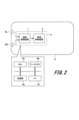
- FIG. 1 is a configuration diagram of an example of an environment recognition device according to an embodiment of the present invention.
- 1 is a diagram showing an example of an overall configuration and a hardware configuration installed in a vehicle according to an embodiment of the present invention
- FIG. 3 is a flowchart illustrating an example of environment recognition processing according to an embodiment of the present invention.
- FIG. 3 is a diagram showing feature extraction processing according to an embodiment of the present invention. It is a flowchart which shows the cost calculation processing example of the example of one embodiment of this invention. It is a figure showing cost calculation processing of an example of one embodiment of the present invention.
- FIG. 3 is a diagram showing cost correction processing according to an embodiment of the present invention.
- FIG. 3 is a diagram illustrating a kernel integration method in cost calculation processing according to an embodiment of the present invention.
- FIG. 6 is a diagram illustrating a method of generating a kernel for a right feature map in cost calculation processing according to an embodiment of the present invention.
- FIG. 7 is a diagram illustrating a method of generating a kernel for a left feature map in cost calculation processing according to an embodiment of the present invention.
- 12 is a flowchart when processing is performed for every fixed number of rows in cost calculation processing according to an embodiment of the present invention.
- 3 is a flowchart showing flow calculation processing according to an embodiment of the present invention.
- FIG. 1 is a functional block diagram showing the configuration of an environment recognition device 1.
- the environment recognition device 1 of this embodiment is configured with a camera, a computer, a memory, a storage device, etc., as described later, and the computer executes a control program stored in the memory etc. to control various functions. It works as.
- the environment recognition device 1 includes an image acquisition section 10, a feature extraction section 20, a cost calculation section 30, a cost aggregation section 40, and a matching section 50 as functional sections realized by the operation of a camera and a computer.
- the image acquisition unit 10 includes a first image storage unit 11 and a second image storage unit 12, and performs image acquisition processing to acquire a plurality of images captured by a camera.
- the first image storage section 11 and the second image storage section 12 acquire two left and right images taken at the same time.
- the first image storage section 11 and the second image storage section 12 acquire a plurality of images taken at different times.
- the feature extraction unit 20 includes a convolution calculation unit 21 and a feature extraction parameter storage unit 22.
- the convolution calculation unit 21 performs a convolution calculation on the plurality of images acquired by the image acquisition unit 10.
- the feature extraction parameter storage unit 22 stores kernel parameters used for convolution. The kernel used for convolution is determined by learning so as to minimize a predetermined loss function.
- the cost calculation unit 30 performs a cost calculation process to calculate the cost related to the correspondence between the plurality of images acquired by the image acquisition unit 10.
- the cost calculation unit 30 includes a first image convolution calculation unit 31 and a second image convolution calculation unit 32, and the first image convolution calculation unit 31 stores data in a first parameter storage unit 33.
- a convolution operation is executed using the stored first parameter
- the second image convolution operation section 32 executes a convolution operation using the second parameter stored in the second parameter storage section 34 .
- the convolution calculation results in each of the image convolution calculation units 31 and 32 are integrated by an integration unit 35.
- this cost calculation unit 30 calculates the cost related to the parallax between the left and right images, and in the case of a monocular camera, it calculates the cost related to the flow between images captured at different times.
- the image convolution calculation units 31 and 32 independently perform convolution calculations on each of the feature maps calculated by the feature extraction unit 20, and the results are integrated by the integration unit 35 to calculate the cost.
- a map is calculated.
- the kernel used in the convolution operation is determined to minimize a predetermined loss function.
- the cost aggregation unit 40 includes a convolution calculation unit 41 and a feature extraction parameter storage unit 42.
- the convolution calculation unit 41 corrects the cost map by performing a convolution calculation on the cost map calculated by the cost calculation unit 30.
- the feature extraction parameter storage unit 42 stores parameters of the convolution kernel executed by the convolution calculation unit 41.
- the kernel used here is a three-dimensional convolution kernel, which is determined to minimize a predetermined loss function.
- the matching unit 50 determines correspondence among the plurality of images acquired by the image acquisition unit 10 by having the cost analysis unit 51 analyze the cost map calculated and corrected by the cost aggregation unit 40. That is, the matching unit 50 determines the parallax between images in the case of a stereo camera, and determines the flow in the case of a monocular camera.
- the cost analysis unit 51 can execute SoftArgMin processing and analysis processing using a kernel.
- the feature extraction unit 20, cost calculation unit 30, cost aggregation unit 40, and matching unit 50 use a kernel determined by learning to minimize a predetermined loss function. These kernels are determined by comparing the matching result determined by the matching unit 50 with the correct value data and minimizing the defined loss function. In the case of a stereo camera, the loss to parallax between images is minimized, and in the case of a monocular camera, the loss to flow between images is minimized.
- FIG. 2 shows the configuration of a vehicle 5 equipped with a computer 4 including an environment recognition device 1 and a vehicle control device 2 according to this embodiment.
- Vehicle (automobile) 5 is equipped with on-vehicle cameras 3L and 3R for monitoring the front.
- the two vehicle-mounted cameras 3L and 3R are stereo cameras that obtain a left image and a right image, but one camera may be connected to the environment recognition device 1.
- Images captured by the on-vehicle cameras 3L and 3R are supplied to the environment recognition device 1 in the computer 4.
- the environment recognition device 1 executes image processing of captured images and performs environment recognition processing. Note that when the environment recognition device 1 recognizes the environment, it may use not only images captured by the vehicle-mounted cameras 3L and 3R, but also other detection mechanisms such as a radar (not shown).
- the environment information recognized by the environment recognition device 1 is sent to the vehicle control device 2, which is also configured in the computer 4, and the running of the vehicle 5 is controlled.
- the environment recognition device 1 and the vehicle control device 2 may be configured with separate computers.
- the computer 4 in which the environment recognition device 1 and the vehicle control device 2 are built-in includes a CPU (central processing unit) 4a, a work memory 4b, a storage section 4c, and an interface (I/F) 4d. , these are connected to each other so that data can be transferred.
- the CPU 4a executes the program stored in the storage unit 4c in the work memory 4b.
- each processing section that performs environment recognition processing and the like is configured in the work memory 4b.
- the storage unit 4c stores programs for performing environment recognition processing and vehicle control, as well as images, control data, and the like.
- the interface 4d performs input processing of image data from the on-vehicle cameras 3L and 3R, detection data from various sensors, and output processing of vehicle control data.
- FIG. 3 is a flowchart showing a process of calculating parallax by the environment recognition device 1.
- the environment recognition device 1 sequentially executes an image acquisition process (P101), a feature extraction process (P102), a matching cost calculation process (P103), a cost correction process (P104), and a parallax calculation process (P105).
- P101 image acquisition process
- P102 feature extraction process
- P103 matching cost calculation process
- P104 cost correction process
- P105 parallax calculation process
- the image acquisition unit 10 acquires data of left and right images of the stereo camera.
- the feature extraction unit 20 generates a feature map by performing a convolution operation on the left image and right image acquired in the image acquisition process (P101).
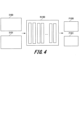
- FIG. 4 shows details of the feature extraction process (P102) by the feature extraction unit 20.
- the feature extraction unit 20 calculates a left feature map F100 and a right feature map F101 for the left image I100 and the right image I101, respectively, using the trained convolutional neural network N100.
- the convolutional neural network N100 is composed of a repeating structure of convolution operations, normalization operations, and activation operations. Batch Normalization is used for the normalization operation, and Rectified Linear Unit is used for the activation. However, Batch Normalization and Rectified Linear Unit are not used only in the final layer.
- the feature extraction unit 20 performs a convolution operation on the left image I100 and the right image I101 using the same convolutional neural network N100. Thereby, the feature extracting unit 20 can extract the same feature amount for locations that look the same. Further, the convolutional neural network N100 uses parameters estimated by learning, which will be described later.
- the cost calculation unit 30 uses the left feature map F100 and the right feature map F101 calculated in the feature extraction process (P102) to calculate the cost for each parallax. generate.
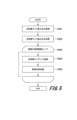
- FIG. 5 is a flowchart showing details of the matching cost calculation process (P103) by the cost calculation unit 30.
- the cost calculation unit 30 performs left feature map convolution process (P201), right feature map convolution process (P202), and cost generation corresponding to each disparity (P203).
- the cost calculation unit 30 performs shift processing of the left feature map (P204), and then performs element addition processing of the right feature map and the left feature map (P205). generates a cost corresponding to each parallax.
- the shift processing of the left feature map (P204) and the element addition processing of the right feature map and the left feature map (P205) are repeatedly executed within the search range of cost generation (P203) corresponding to the parallax.
- the cost calculation unit 30 performs normalization using Batch Normalization and activation using Rectified Linear Unit on the generated cost.
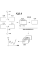
- FIG. 6 shows an example of the processing status of the matching cost calculation process (P103) by the cost calculation unit 30 described in the flowchart of FIG.
- the cost calculation unit 30 obtains the left feature map F110 by performing a convolution operation LC using the convolution parameter KL on the left feature map F100.
- the cost calculation unit 30 obtains the right feature map F111 by performing a convolution operation RC using the convolution parameter KR on the right feature map F101.
- the subsequent processing is executed a number of times according to the calculated parallax range (for example, 64 pixels, etc.).
- cost generation processing corresponding to a 4-pixel parallax will be explained.
- the cost calculation unit 30 shifts the left feature map F110 by 4 pixels to the left with respect to the right feature map F111.
- element addition processing (P205) the cost calculation unit 30 generates a cost map C104 corresponding to the 4-pix parallax by adding elements of the right feature map F111 and the shifted left feature map F110.
- the cost calculation unit 30 executes the shift processing (P204) and the element addition processing (P205) on the left feature map for the number of times (D+1) of the parallax range to be calculated, and combines them in the depth direction of the feature map. By doing this, a cost map C200 is generated. Here, a cost corresponding to each parallax is stored in each position of the cost map C200.
- the cost calculation unit 30 can use a plurality of kernels as the convolution parameters KL and KR.
- the sizes of the left feature map F110 and the right feature map F111 become (HL, WL, WL) and (HR, WR, CR), respectively.
- HL, WL, and WL indicate the height, width, and channel of the left feature map F110, respectively.
- HR, WR, and CR indicate the height, width, and channel of the right feature map F111, respectively.
- the cost calculation unit 30 calculates the size (D+1 , HR, WR, CR) is calculated. Then, the cost corresponding to the parallax is stored for each channel at each position in the cost map C200 calculated in this way.
- the convolution parameters KL and KR are parameters estimated by learning described later.
- the cost aggregation unit 40 performs a convolution operation using the convolutional neural network N200 to correct the cost map C201 on the cost map C200 calculated in the matching cost calculation process (P103). Calculate.
- the size of the cost map C201 is (D+1, HR, WR, 1), and the cost for each parallax is stored at each position.
- the corrected cost map C201 costs corrected in consideration of costs of surrounding pixels are stored.
- the convolution operation unit 41 of the cost aggregation unit 40 uses a three-dimensional convolution kernel to perform convolution operations on the width, height, and depth directions of the cost map C200.
- the convolutional neural network N200 is composed of a repeating structure of convolution operations, normalization operations, and activation operations.
- the convolutional neural network N200 is an encoder-decoder type network that downsamples the input cost map and then upsamples it.
- the kernel used in the neural network N200 is a parameter estimated by learning, which will be described later.
- the cost analysis unit 51 of the matching unit 50 calculates the parallax at each pixel of the right image by analyzing the cost stored in the cost map C201 calculated in the cost correction process (P104). do.
- the cost analysis unit 51 executes a known SoftArgMin process as a cost analysis method. That is, the cost analysis unit 51 performs SoftMax processing in the depth direction D for each position. At this time, the cost analysis unit 51 calculates the probability for each parallax by inverting the sign of the cost. After that, the cost analysis unit 51 calculates the parallax for each pixel by calculating the sum of the parallax value corresponding to the index in the depth direction of the cost map C201 and the probability calculated by SoftMax processing.
- the cost analysis unit 51 of the matching unit 50 performs the above-mentioned calculation on pixels that include correct value data in the estimated parallax image, and uses the average value as a loss function.
- Feature extraction processing (P102), matching cost calculation processing (P103), cost correction processing (P104), and disparity calculation processing (P105) are all composed of only differentiable operations, and disparity calculation processing (P105) By defining a loss function for and minimizing it, parameters for feature extraction processing (P102), matching cost calculation processing (P103), and cost correction processing (P104) are determined.
- the environment recognition device 1 of this embodiment performs a convolution operation once for the right image and the left image independently, and calculates the matching cost by integrating the results. can do.
- the matching cost has been calculated by connecting the right image and the left image in the parallax direction and performing a three-dimensional convolution operation once, but this requires convolution calculations for the number of times in the parallax search range.
- the number of convolution operations can be reduced, and the amount of calculations can be reduced.
- the environment recognition device 1 of this embodiment shifts the left image among the convolution calculation results of the right image and the left image, and performs element addition processing on the shifted result.
- the matching cost is calculated by executing In this way, the environment recognition device 1 of this embodiment can generate matching costs faster by generating costs by image shifting and simple addition processing without using complex calculations. can.
- the environment recognition device 1 of this embodiment corrects the cost calculated in the matching cost calculation process (P103) in the cost correction process (P104). As a result, in the environment recognition device 1 of this embodiment, even if the cost calculated in the matching cost calculation process (P103) includes an error, it can be corrected using surrounding costs, and the Parallax can be calculated with high accuracy.
- FIG. 8 is a diagram illustrating the configuration and procedure of the cost calculation unit 30 during learning.
- the process is performed on the left feature map F100 and the right feature map F101.
- the cost calculation unit 30 shifts the left feature map F100 with respect to the right feature map F101 by the number of times in the disparity search range (D+1 pix) to generate left and right pairs corresponding to each disparity.
- the feature map combined in the channel direction without shifting is F0 with "no shift”
- the feature map shifted by 1 pix and combined is F1 with "1 pix shift”
- the feature map combined with Dpix shift is FD with "Dpix shift”. It is.
- the cost calculation unit 30 generates a matching cost by further combining these D+1 pairs in the depth direction and performing a convolution operation using the three-dimensional convolution kernel K100.
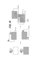
- FIG. 9 are diagrams showing a method for determining convolution parameters KL and KR using the three-dimensional convolution kernel K100 obtained during learning.
- the size of the three-dimensional convolution kernel K100 in the depth direction is "3", so it is a convolution kernel for three left and right pairs.
- the three-dimensional convolution kernel K100 can be considered to be an independent convolution kernel for each feature map (F0R, F1R, F2R, F0L, F1L, F2L).
- F0R, F1R, and F2R indicate the right feature maps of the three left and right pairs
- F0L, F1L, and F2L indicate the left feature maps of the three left and right pairs.
- F0R, F1R, and F2R are the same feature map
- F1L is a map shifted by 1 pix with F0L as a reference
- F2L is a map shifted by 2 pixels with F0L as a reference. It has become.
- convolution kernels for F0R, F1R, and F2R are assumed to be K0R, K1R, and K2R.
- convolution kernels for F0L, F1L, and F2L are assumed to be K0L, K1L, and K2L.
- the cost calculation unit 30 integrates the kernels K0R, K1R, and K2R to generate a two-dimensional convolution kernel K101 for the right feature map.
- the cost calculation unit 30 also integrates the kernels K0L, K1L, and K2L to generate a two-dimensional convolution kernel K102 for the left feature map.
- the two-dimensional convolution kernel K101 for the right feature map and the two-dimensional convolution kernel K102 for the left feature map that are generated correspond to the convolution parameters KR and KL used at the time of inference shown in FIG. 6, respectively.
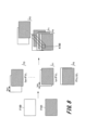
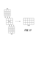
- FIG. 11 shows a method for generating a two-dimensional convolution kernel K102 for the left feature map.
- the cost calculation unit 30 performs element addition with respect to the convolution kernel K1L by shifting the convolution kernel K0L by one pixel to the left. That is, the cost calculation unit 30 adds each element in the second column of the convolution kernel K0L to each element in the first column of the convolution kernel K1L.
- the cost calculation unit 30 performs element addition by shifting the convolution kernel K2L to the right by one pixel with respect to the convolution kernel K1L added to the convolution kernel K0L.
- the cost calculation unit 30 adds each element in the first column of the convolution kernel K2L to each element in the second column of the convolution kernel K1L. Note that in the element addition process for the first column of the convolution kernel K0L and the third column of the convolution kernel K2L, elements are added to the 0th column and the 4th column of the convolution kernel K1L, which do not exist. In this case, the cost calculation unit 30 assumes that all elements in the 0th and 4th columns of the convolution kernel K1L are 0, and executes the element addition process.
- the two-dimensional convolution kernel K102 for the left feature map generated by the procedure described above has a size larger in the horizontal direction than the sizes of the convolution kernels K0R, K1R, and K2R.
- the environment recognition device 1 of this embodiment integrates the three-dimensional convolution kernel obtained during learning and uses it as a two-dimensional convolution kernel during inference. By doing so, the environment recognition device 1 according to the present embodiment can execute a model learned using a three-dimensional convolution kernel with a smaller amount of calculation without relearning during inference. Furthermore, when comparing the number of parameters of the three-dimensional convolution kernel used during learning and the number of parameters used during inference, the number of parameters used during inference is smaller. This makes it possible to perform parallax calculation with less memory usage.
- the matching cost calculation process (P301) the same process as the process of P201 to P205 shown in the flowchart of FIG. 5 is executed for a certain number of consecutive rows.
- the individual processes (P201, P202, P203, P204, P205) performed on a certain number of rows are as described with reference to FIG.
- the cost calculation unit 30 generates the final cost map by repeating the processing of P201 to P205 for every fixed number of rows.
- the cost calculation unit 30 can reduce the amount of memory used by generating a cost map for each constant number of consecutive rows and dividing the processing area. Moreover, in the case of an execution environment that allows distributed inference, the cost calculation unit 30 can shorten the inference time by performing distributed inference every certain number of consecutive lines and integrating the results.
- the feature extraction unit 20 can also make the size of the output feature map smaller than the size of the input image.
- the feature extraction unit 20 can output a feature map smaller in size than the input image by executing a convolution operation with a stride of 2 or more using the convolution operation unit 21 in the convolution neural network (N100).
- the feature map output by executing convolution with stride 2 twice by the convolution calculation unit 21 has a size that is 1/4 of the input image. That is, 1 pix of the output feature map corresponds to 4 pixels of the input image.
- the cost calculation unit 30 executes the cost calculation process 16 pixels times, which corresponds to 1/4 of the parallax search range, in the matching cost calculation process (P103). In this way, according to the feature extraction process of this embodiment, it is possible to change the configuration to output feature maps of various sizes.
- the convolution calculation unit 41 when outputting a cost map that is larger than the input, in the convolutional neural network (N200), the convolution calculation unit 41 should set a stride number that is larger than the number of strides used for encoding at the time of decoding. You can output large size feature maps.
- the convolution calculation unit 41 sets a stride number smaller than the number of strides used for encoding at the time of decoding. Feature maps can be output.
- the cost calculation unit 30 cuts the left and right ends of the right feature map (F101) by 1 pix. Then, the cost calculation unit 30 sets the size of the right feature map (F101) to WR-2.
- the size of the feature map thus output is (D+1, WR-4, H).
- the cost calculation unit 30 removes the left and right ends of the input right feature map (F101) by 1 pix, and sets the size of the right feature map (F101) to WR-2. Thereafter, the cost calculation unit 30 performs a convolution operation on the right feature map (F101) and the left feature map (F100), respectively, using the integrated kernel. Then, the cost calculation unit 30 further removes 1 pix from the left and right ends of the right feature map (F111), and sets the size of the right feature map (F111) to WR-4.
- FIG. 13 shows processing in flow calculation of operation example 2 in this embodiment.
- image acquisition processing P401
- feature extraction processing P402
- matching cost calculation processing P403
- cost correction processing P404
- optical flow calculation processing P405
- image acquisition processing P401
- the image acquisition unit 10 acquires two images taken at time T-1 and time T.
- feature extraction process P402
- the feature extraction unit 20 uses a convolutional neural network for each of the image captured at time T-1 and the image captured at time T acquired in the image acquisition process (P401). Generate a feature map from each image using .
- the difference from the feature extraction process in the parallax calculation shown in FIG. 4 is that the feature extraction unit 20 calculates feature maps for two images at time T-1 and time T, instead of for the left and right images. be. Further, the kernel used in the convolution process of the convolutional neural network is estimated by learning described later.
- the cost calculation unit 30 calculates the cost for each flow using the feature map F201 at time T-1 and the feature map F200 at time T obtained in the feature extraction process (P402). calculate.
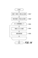
- FIG. 14 is a flowchart showing the matching cost calculation process (P403) by the cost calculation unit 30.
- the cost calculation unit 30 performs the feature map convolution process at time T-1 (P201') and the time T feature map convolution process (P202'). Then, the cost calculation unit 30 performs cost calculation corresponding to the candidate flows by the number of each flow candidate (7 ⁇ 7) (P203).
- the feature map convolution process at time T-1 (P201') and the time T feature map convolution process (P202') are respectively the left image feature map convolution process (P201) and the right image feature map convolution process explained in FIG.
- the image at (P202) only changes to an image at time T-1 and an image at time T, respectively.
- the cost calculation unit 30 shifts the feature map at time T-1 by the amount of the candidate flow (P204). After that, the cost calculation unit 30 calculates the cost for the flow by performing element addition processing on the shifted feature map at time T-1 and the feature map at time T (P205). The cost calculation unit 30 repeatedly performs cost calculation (P203) corresponding to this candidate flow within the search range.
- FIG. 15 shows the processing procedure of the matching cost calculation process (P403) of FIG. 13 by the cost calculation unit 30.
- the cost calculation unit 30 executes a convolution operation C(T-1) using the convolution parameter K(T-1) on the time T-1 feature map F201 to calculate a time T-1 feature map F211. .
- the cost calculation unit 30 also performs a convolution operation C(T) using the convolution parameter K(T) on the feature map F200 at time T to calculate a feature map F210 at time T. Thereafter, the cost calculation unit 30 calculates costs for the candidate flows (-3, -3) to (3, 3). Then, in cost generation for candidate flow (-3, -3), the cost calculation unit 30 shifts the time T-1 feature map F211 by 3 pixels to the left and 3 pixels upward with respect to the time T feature map F210. , executes element addition processing.
- the cost calculation unit 30 sequentially executes the above processing in the range of (-3, -3) to (3, 3), calculates the cost corresponding to each candidate flow, and connects each cost in the depth direction. By doing so, a cost map C200 is generated. A cost corresponding to a flow candidate is stored in each position of the cost map (C200).
- the cost map C200 stores costs for each channel. Furthermore, in the element addition process of the feature map F210 at time T and the feature map F211 at time T-1, the cost calculation unit 30 shifts the feature map F211 at time T-1. As a result, the feature map F210 at time T and the feature map F211 at time T-1 no longer overlap, and element addition processing may not be possible. Therefore, in order to prevent the element addition process from being impossible in the cost calculation unit 30, the feature extraction unit 20 specifies a wider range for the image at time T-1 than for the image at time T in the feature extraction process (P402). is input.
- the convolution calculation unit 41 executes the convolution process as shown in FIG. 7 on the cost map C200 calculated in the matching cost calculation process (P403).
- a cost map is generated that takes surrounding areas into consideration.
- a feature map having a size of (H, W, 2) is generated by a convolution operation performed by the cost analysis unit 51 on the cost map corrected in the cost correction process (P404). be done.
- H and W indicate the height and width of the feature map, respectively, and flow coordinates (horizontal flow, vertical flow) are stored for each position.
- the feature extraction process (P402), matching cost calculation process (P403), cost correction process (P404), and optical flow calculation process (P405) shown in FIG. 13 use the kernel determined by learning. Then the convolution operation is performed.
- a loss function is defined for the flow calculated in the optical flow calculation process (P405), and the defined loss function is minimized.
- the loss function calculates the absolute value of the difference between the horizontal flow and the vertical flow of correct value data for each of the horizontal flow and the vertical flow. Therefore, the error for each pixel is the sum of the absolute values of the differences between the horizontal flow and the vertical flow. This error is calculated only for pixels in which correct value data is stored, and the average value is used as a loss function.
- the environment recognition device 1 of this embodiment executes the convolution operation only once for the image at time T and the image at time T-1 in calculating the matching cost in flow calculation. , it becomes possible to calculate costs for flows. Therefore, the amount of calculation can be reduced compared to the case where three-dimensional convolution calculation is performed for each flow candidate.
- the kernel determined during learning is used in the matching cost calculation process (P403) during inference.
- an integrated kernel determined by learning can also be used in the matching cost calculation process (P403).
- by generating a kernel to be used during inference through the process described below it is possible to obtain the same output results as the configuration during learning.
- FIG. 16 shows matching cost calculation processing (P403) during learning.
- the cost calculation unit 30 creates a pair of feature maps of the feature map F200 at time T and the feature map F201 at time T-1 for each candidate flow. Specifically, for the candidate flow (-3, -3), the cost calculation unit 30 shifts the feature map F201 at time T-1 by 3 pixels to the left with respect to the feature map F200 at time T, and shifts the feature map F201 at time T-1 upward by 3 pixels. , and create a feature map pair F(-3,-3). The cost calculation unit 30 generates F(-3,-3) to F(3,3) by executing this procedure a number of times corresponding to each candidate flow.
- the cost calculation unit 30 connects the generated feature map pairs F(-3,-3) to F(3,3) in the depth direction and executes a convolution operation using a three-dimensional convolution kernel (K100). do.
- the three-dimensional convolution kernel (K100) used at this time has a size of (49, 3, 3).
- the three-dimensional convolution kernel (K100) has a size of 3x3 in the spatial direction, and all feature up pairs F(-3,-3) to F(3,3) in the depth direction. It becomes a size that can be convolved.
- the cost calculation unit 30 integrates and uses the three-dimensional convolution kernel (K100) used during learning.
- the convolution parameter K(T-1) and the convolution parameter K(T) shown in FIG. 15 are an integrated kernel used at the time of inference.
- the method of integration is basically a procedure similar to the first operation example. Specifically, the cost calculation unit 30 calculates the convolution parameter K(T) by adding elements of each kernel for the feature map F200 at time T among the three-dimensional convolution kernels (K100). (T) is generated. Furthermore, for the convolution parameter K(T-1), the cost calculation unit 30 uses each kernel for the feature map F201 at time T-1 among the three-dimensional convolution kernels (K100).
- the cost calculation unit 30 adds the kernels for F(-3,-3) to F(3,3) to the kernel for the feature map pair F(0,0), but at this time, Shift F(-3,-3) to F(3,3) and add the elements.
- the cost calculation unit 30 shifts the kernel by 3 pixels to the left and 3 pixels upward, and executes the element addition.
- the cost calculation unit 30 generates the convolution parameter K(T-1).
- the difference from operation example 1 is that the kernel is not only shifted in the horizontal direction but also in the vertical direction.
- the three-dimensional convolution kernel obtained during learning is integrated during inference and used as a two-dimensional convolution kernel.
- a model learned using a three-dimensional convolution kernel can be executed with a smaller amount of calculations without having to be retrained during inference.
- the number of parameters used during inference is smaller. This makes it possible to perform parallax calculation with less memory usage.
- the present invention has been described above using the first and second operational examples according to the embodiments, the present invention is not limited to the above-described embodiments.
- the configuration includes the cost aggregation unit 40.
- the parallax or flow may be calculated without the cost aggregation unit 40.
- the parallax calculation corresponding to the right image among the left and right images of the stereo camera was performed, but it can also be used to calculate the parallax corresponding to the left image.
- the flow calculation corresponding to the image at time T-1 and the image at time T of the monocular camera was executed, but the flow calculation corresponding to the image at time T-2 before time T-1 and the image at time T
- the flow of images may be calculated. That is, operation example 2 can be applied to calculation of flows between arbitrary frames.
- the network structure and kernel size explained in the figures are only a concrete example, and the above-mentioned The structure or size may be different.
- the embodiments described so far have been described in detail to explain the present invention in an easy-to-understand manner, and are not necessarily limited to those having all the configurations described.
- the environment is recognized from the image taken by the camera mounted on the vehicle shown in Fig. 2, and the vehicle is controlled. It may be applied to the case of recognizing the environment from the camera.
- the use of environment recognition results is not limited to vehicle control either.
- the configuration diagrams shown in Figures 1 and 2 only control lines and information lines that are considered necessary for explanation are shown, and not all control lines and information lines are necessarily shown in the product. . In reality, almost all components may be considered to be interconnected.
- the flow of the operational processing in the flowcharts shown in FIG. 3 and the like is also an example, and as long as the processing results are the same, the order of some of the processing may be changed or a plurality of processing may be executed simultaneously.
- the processing performed within the environment recognition device of the present invention is performed by executing a program (software), and for example, an existing computer (information processing device) can execute the processing described in the embodiment example.
- a program software
- an existing computer information processing device
- the program information in this case can be stored in various recording media such as memory, hard disk, SSD (Solid State Drive), IC card, SD card optical disk, etc.
- the environment recognition device is configured with a computer executed under the control of the CPU, but some or all of the functions performed by the environment recognition device can be implemented using an FPGA (Field Programmable Gate Array). It may also be realized by dedicated hardware such as or ASIC (Application Specific Integrated Circuit).
- SYMBOLS 1...Environment recognition device 2...Vehicle control device, 3L...Vehicle camera, 4...Computer, 4a...CPU, 4b...Work memory, 4c...Storage part, 4d...Interface, 5...Vehicle, 10...Image acquisition part, 11 ...Image storage unit, 12...Image storage unit, 20...Feature extraction unit, 21...Convolution calculation unit, 22...Feature extraction parameter storage unit, 30...Cost calculation unit, 31...Image convolution calculation unit, 32...Image convolution calculation unit , 33... Parameter storage section, 34... Parameter storage section, 35... Integration section, 40... Cost aggregation section, 41... Convolution calculation section, 42... Feature extraction parameter storage section, 50... Matching section, 51... Cost analysis section
Landscapes
- Engineering & Computer Science (AREA)
- Theoretical Computer Science (AREA)
- General Physics & Mathematics (AREA)
- Computer Vision & Pattern Recognition (AREA)
- Physics & Mathematics (AREA)
- Evolutionary Computation (AREA)
- Multimedia (AREA)
- Databases & Information Systems (AREA)
- Medical Informatics (AREA)
- Software Systems (AREA)
- General Health & Medical Sciences (AREA)
- Computing Systems (AREA)
- Artificial Intelligence (AREA)
- Health & Medical Sciences (AREA)
- Image Analysis (AREA)
Abstract
第一および第二の画像から第一の特徴マップおよび第二の特徴マップを求める特徴抽出部と、各特徴マップに対して畳み込み演算を行うことで各部分領域の対応関係に関する確からしさを表現したマッチングコストを求めるコスト算出部と、マッチングコストを解析することで第一の画像と第二の画像の対応関係を確定させるマッチング部とを備える。コスト算出部は、各特徴マップのそれぞれに対して、コスト算出用のパラメータを利用した畳み込み演算を実行して畳み込み演算結果を求め、各畳み込み演算結果を統合してマッチングコストを求める。
Description
本発明は、環境認識装置および環境認識方法に関する。
複数の画像間における画素毎の対応関係を算出することで、画像に撮像された対象までの距離や物体のフローを算出する技術が知られている。この技術は、車両に搭載されたカメラを利用して、これらの距離やフロー情報を算出することで、当該車両の周囲の他車両などの挙動を解析することができ、予防安全機能に利用することができる。
特許文献1には、ステレオカメラを使用して、左右画像間の対応関係を算出する手法の一例が開示されている。すなわち、特許文献1には、深層学習に基づく手法に関する技術が記載されている。具体的には、特許文献1に記載される技術は、左右の特徴マップを視差値だけずらして連結し、それら連結された特徴マップを視差の探索範囲分さらに連結することで3次元マッチングコスト特徴を生成するようにしている。また、この3次元マッチングコスト特徴はグループ化相互相関特徴とさらに連結される。その後、3次元畳み込み処理を複数回実行することで、各画素に対して視差を算出している。
特許文献1に記載されるような3次元マッチングコスト特徴に対する3次元畳み込み処理は、幅、高さ、視差方向に対する畳み込み処理になり、処理負荷が高いという問題がある。特に、3次元マッチングコスト特徴に対する1回目の畳み込み処理は、幅、高さ、視差のサイズが大きいため、計算リソースの少ないデバイスへの適用が困難であり、演算量の削減を行うことが要求されていた。
本発明は、かかる課題に鑑み、複数の画像間における画素毎の対応関係をより少ない演算量で算出可能な環境認識装置および環境認識方法を提供することを目的とする。
上記課題を解決するために、例えば請求の範囲に記載の構成を採用する。
本願は、上記課題を解決する手段を複数含んでいるが、その一例を挙げるならば、環境認識装置として、
第一の画像と第二の画像を取得する画像取得部と、
第一の画像の複数の部分領域に対して特徴量を求めることによって得られる第一の特徴マップと、第二の画像の複数の部分領域に対して特徴量を求めることによって得られる第二の特徴マップと、を求める特徴抽出部と、
第一の特徴マップおよび第二の特徴マップに対して畳み込み演算を行うことで各部分領域の対応関係に関する確からしさを表現したマッチングコストを求めるコスト算出部と、
コスト算出部で求めたマッチングコストを解析することで第一の画像と第二の画像の対応関係を確定させるマッチング部と、を備える。
そして、コスト算出部は、第一の特徴マップと第二の特徴マップのそれぞれに対して、コスト算出用の第一のパラメータと第二のパラメータを利用した畳み込み演算を実行することで第一の畳み込み演算結果と第二の畳み込み演算結果をそれぞれ求め、第一の畳み込み演算結果と第二の畳み込み演算結果とを統合することでマッチングコストを求めるようにした。
本発明によれば、複数の画像間における画素毎の対応関係をより少ない演算量で算出することができる。
上記した以外の課題、構成および効果は、以下の実施形態の説明により明らかにされる。
上記した以外の課題、構成および効果は、以下の実施形態の説明により明らかにされる。
以下、本発明の一実施の形態例を、添付図面を参照して説明する。
図1は、環境認識装置1の構成を示す機能ブロックである。
本実施の形態例の環境認識装置1は、後述するようにカメラ、コンピュータ、メモリ、および記憶装置などで構成されており、コンピュータがメモリ等に格納された制御プログラムを実行することにより各種機能部として動作する。
図1は、環境認識装置1の構成を示す機能ブロックである。
本実施の形態例の環境認識装置1は、後述するようにカメラ、コンピュータ、メモリ、および記憶装置などで構成されており、コンピュータがメモリ等に格納された制御プログラムを実行することにより各種機能部として動作する。
[環境認識装置の構成]
図1に示すように、環境認識装置1は、カメラやコンピュータの動作により実現される機能部として画像取得部10、特徴抽出部20、コスト算出部30、コスト集約部40、及びマッチング部50を有している。
画像取得部10は、第一の画像格納部11と第二の画像格納部12を有し、カメラで撮像された複数の画像を取得する画像取得処理を行う。ステレオカメラの場合には、第一の画像格納部11と第二の画像格納部12は、同時刻に撮像された左右の2枚の画像を取得する。また、単眼カメラの場合、第一の画像格納部11と第二の画像格納部12は、異なる時刻に撮像された複数枚の画像を取得する。
図1に示すように、環境認識装置1は、カメラやコンピュータの動作により実現される機能部として画像取得部10、特徴抽出部20、コスト算出部30、コスト集約部40、及びマッチング部50を有している。
画像取得部10は、第一の画像格納部11と第二の画像格納部12を有し、カメラで撮像された複数の画像を取得する画像取得処理を行う。ステレオカメラの場合には、第一の画像格納部11と第二の画像格納部12は、同時刻に撮像された左右の2枚の画像を取得する。また、単眼カメラの場合、第一の画像格納部11と第二の画像格納部12は、異なる時刻に撮像された複数枚の画像を取得する。
特徴抽出部20は、畳み込み演算部21と特徴抽出パラメータ格納部22とを有する。
畳み込み演算部21は、画像取得部10で取得した複数枚の画像に対して、畳み込み演算を実行する。特徴抽出パラメータ格納部22には、畳み込みに利用されるカーネルのパラメータが格納される。畳み込みに利用されるカーネルは、所定のロス関数を最小化するように学習により決定される。
畳み込み演算部21は、画像取得部10で取得した複数枚の画像に対して、畳み込み演算を実行する。特徴抽出パラメータ格納部22には、畳み込みに利用されるカーネルのパラメータが格納される。畳み込みに利用されるカーネルは、所定のロス関数を最小化するように学習により決定される。
コスト算出部30は、画像取得部10で取得された複数の画像の対応関係に関するコストを算出するコスト算出処理を行う。具体的には、コスト算出部30は、第一の画像畳み込み演算部31と第二の画像畳み込み演算部32とを備え、第一の画像畳み込み演算部31は、第一のパラメータ格納部33に格納された第一のパラメータによる畳み込み演算を実行し、第二の画像畳み込み演算部32は、第二のパラメータ格納部34に格納された第二のパラメータによる畳み込み演算を実行する。
各画像畳み込み演算部31、32での畳み込み演算結果は、統合部35で統合される。
このコスト算出部30は、ステレオカメラの場合、左右画像間の視差に関するコストを算出し、単眼カメラの場合には異なる時刻に撮像された画像間のフローに関するコストを算出する。コスト算出処理では、特徴抽出部20で算出された特徴マップそれぞれに対して独立に各画像畳み込み演算部31、32で畳み込み演算が実施され、その結果が統合部35で統合されることで、コストマップが算出される。畳み込み演算で利用するカーネルは、所定のロス関数を最小化するように決定されたものである。
このコスト算出部30は、ステレオカメラの場合、左右画像間の視差に関するコストを算出し、単眼カメラの場合には異なる時刻に撮像された画像間のフローに関するコストを算出する。コスト算出処理では、特徴抽出部20で算出された特徴マップそれぞれに対して独立に各画像畳み込み演算部31、32で畳み込み演算が実施され、その結果が統合部35で統合されることで、コストマップが算出される。畳み込み演算で利用するカーネルは、所定のロス関数を最小化するように決定されたものである。
コスト集約部40は、畳み込み演算部41と特徴抽出パラメータ格納部42とを備える。
畳み込み演算部41は、コスト算出部30で算出されたコストマップに対して、畳み込み演算を実施することで、コストマップを補正する。特徴抽出パラメータ格納部42には、畳み込み演算部41で実行する畳み込みカーネルのパラメータが格納される。
ここで利用されるカーネルは3次元畳み込みカーネルであり、所定のロス関数を最小化するように決定されたものである。
マッチング部50は、コスト集約部40で算出され、補正されたコストマップをコスト解析部51が解析することで、画像取得部10で取得した複数枚の画像における対応関係を決定する。すなわち、マッチング部50は、ステレオカメラの場合には画像間の視差を決定し、単眼カメラの場合にはフローを決定する。コスト解析部51では、SoftArgMin処理やカーネルを利用した解析処理を実行することができる。
特徴抽出部20、コスト算出部30、コスト集約部40、及びマッチング部50では、所定のロス関数を最小化する学習により決定されたカーネルが利用される。これらカーネルは、マッチング部50で決定したマッチング結果と正解値データを比較して定義されたロス関数を最小化することで決定される。ステレオカメラの場合には、画像間の視差に対するロスが最小化され、単眼カメラの場合には、画像間のフローに対するロスが最小化される。
[環境認識装置が搭載された車両の構成]
図2は、本実施の形態例の環境認識装置1と車両制御装置2を含むコンピュータ4が搭載された車両5の構成を示す。
車両(自動車)5には、前方監視を行うために車載カメラ3L、3Rが設置されている。ここでは、2台の車載カメラ3L、3Rは、左画像と右画像を得るステレオカメラとしたが、1台のカメラが環境認識装置1に接続される場合もある。
図2は、本実施の形態例の環境認識装置1と車両制御装置2を含むコンピュータ4が搭載された車両5の構成を示す。
車両(自動車)5には、前方監視を行うために車載カメラ3L、3Rが設置されている。ここでは、2台の車載カメラ3L、3Rは、左画像と右画像を得るステレオカメラとしたが、1台のカメラが環境認識装置1に接続される場合もある。
車載カメラ3L、3Rで撮像された画像は、コンピュータ4内の環境認識装置1に供給される。環境認識装置1は、撮像画像の画像処理を実行し、環境認識処理を行う。なお、環境認識装置1が環境を認識する際には、車載カメラ3L、3Rによる撮像画像だけでなく、不図示のレーダなどの他の検出機構を併用する場合もある。
環境認識装置1で認識された環境の情報は、同じくコンピュータ4内に構成される車両制御装置2に送られ、車両5の走行などが制御される。但し、環境認識装置1と車両制御装置2とは、それぞれ別のコンピュータで構成するようにしてもよい。
環境認識装置1で認識された環境の情報は、同じくコンピュータ4内に構成される車両制御装置2に送られ、車両5の走行などが制御される。但し、環境認識装置1と車両制御装置2とは、それぞれ別のコンピュータで構成するようにしてもよい。
図2に示すように、環境認識装置1と車両制御装置2が内蔵されたコンピュータ4は、CPU(中央処理ユニット)4aとワークメモリ4bと記憶部4cとインターフェース(I/F)4dとを備え、これらが相互にデータ転送可能に接続されている。
CPU4aは、記憶部4cが記憶したプログラムをワークメモリ4b内で実行する。これにより、ワークメモリ4b内に環境認識処理などを行う各処理部が構成される。
記憶部4cは、環境認識処理や車両制御を行うプログラムを記憶すると共に、画像や制御データなどを記憶する。
インターフェース4dは、車載カメラ3L、3Rからの画像データや、各種センサの検出データの入力処理や、車両の制御データの出力処理を行う。
CPU4aは、記憶部4cが記憶したプログラムをワークメモリ4b内で実行する。これにより、ワークメモリ4b内に環境認識処理などを行う各処理部が構成される。
記憶部4cは、環境認識処理や車両制御を行うプログラムを記憶すると共に、画像や制御データなどを記憶する。
インターフェース4dは、車載カメラ3L、3Rからの画像データや、各種センサの検出データの入力処理や、車両の制御データの出力処理を行う。
[環境認識装置が行う処理の動作例1:ステレオカメラを利用して視差を算出する例]
次に、環境認識装置1が行う動作例1として、ステレオカメラである車載カメラ3L、3Rを利用して視差を算出する動作を説明する。
以降では、ステレオカメラで取得される左右画像のうち、右画像に対して視差を算出する処理を説明する。
次に、環境認識装置1が行う動作例1として、ステレオカメラである車載カメラ3L、3Rを利用して視差を算出する動作を説明する。
以降では、ステレオカメラで取得される左右画像のうち、右画像に対して視差を算出する処理を説明する。
図3は、環境認識装置1による視差を算出する処理を示すフローチャートである。
まず、環境認識装置1は、画像取得処理(P101)、特徴抽出処理(P102)、マッチングコスト算出処理(P103)、コスト補正処理(P104)、及び視差算出処理(P105)を順に実行する。
まず、環境認識装置1は、画像取得処理(P101)、特徴抽出処理(P102)、マッチングコスト算出処理(P103)、コスト補正処理(P104)、及び視差算出処理(P105)を順に実行する。
画像取得処理(P101)において、画像取得部10は、ステレオカメラの左右画像のデータを取得する。
特徴抽出処理(P102)では、画像取得処理(P101)で取得された左画像及び右画像に対して、特徴抽出部20が畳み込み演算を実施することで特徴マップを生成する。
特徴抽出処理(P102)では、画像取得処理(P101)で取得された左画像及び右画像に対して、特徴抽出部20が畳み込み演算を実施することで特徴マップを生成する。
図4は、特徴抽出部20による特徴抽出処理(P102)の詳細を示す。
ここでは、特徴抽出部20は、左画像I100と右画像I101に対して、学習済みの畳み込みニューラルネットワークN100を利用して、左特徴マップF100と右特徴マップF101をそれぞれ算出する。畳み込みニューラルネットワークN100は、畳み込み演算、正規化演算、活性化演算の繰り返し構造から構成される。正規化演算としては、Batch Normalization、活性化としてはRectified Linear Unitが利用される。ただし、最終層のみBatch NormalizationとRectified Linear Unitは利用されない。
ここでは、特徴抽出部20は、左画像I100と右画像I101に対して、学習済みの畳み込みニューラルネットワークN100を利用して、左特徴マップF100と右特徴マップF101をそれぞれ算出する。畳み込みニューラルネットワークN100は、畳み込み演算、正規化演算、活性化演算の繰り返し構造から構成される。正規化演算としては、Batch Normalization、活性化としてはRectified Linear Unitが利用される。ただし、最終層のみBatch NormalizationとRectified Linear Unitは利用されない。
ここで、特徴抽出部20は、左画像I100と右画像I101に対して、同一の畳み込みニューラルネットワークN100を利用して畳み込み演算を実施する。これにより、特徴抽出部20は、同一の見え方をする箇所に対して、同一の特徴量を抽出することができる。また、畳み込みニューラルネットワークN100は、後述する学習により推定されたパラメータを利用する。
図3の説明に戻ると、マッチングコスト算出処理(P103)では、コスト算出部30は、特徴抽出処理(P102)で算出した左特徴マップF100と右特徴マップF101を利用して、各視差に対するコストを生成する。
図3の説明に戻ると、マッチングコスト算出処理(P103)では、コスト算出部30は、特徴抽出処理(P102)で算出した左特徴マップF100と右特徴マップF101を利用して、各視差に対するコストを生成する。
図5は、コスト算出部30によるマッチングコスト算出処理(P103)の詳細を示すフローチャートである。
マッチングコスト算出処理(P103)では、コスト算出部30は、左特徴マップ畳み込み処理(P201)、右特徴マップ畳み込み処理(P202)、及び各視差に対応したコスト生成(P203)を実施する。
各視差に対応したコスト生成(P203)では、コスト算出部30は、左特徴マップのシフト処理(P204)を実施し、その後右特徴マップと左特徴マップの要素加算処理(P205)を実行することで各視差に対応したコストを生成する。
ここで、左特徴マップのシフト処理(P204)と、右特徴マップと左特徴マップの要素加算処理(P205)とは、視差に対応したコスト生成(P203)の探索範囲で繰り返し実行される。
その後、コスト算出部30は、生成したコストに対して、Batch Normalizationによる正規化と、Rectified Linear Unitによる活性化を実行する。
図6は、図5のフローチャートで説明したコスト算出部30によるマッチングコスト算出処理(P103)の処理状況の例を示す。
コスト算出部30は、左特徴マップ畳み込み処理(P201)で、左特徴マップF100に対して、畳み込みパラメータKLを利用した畳み込み演算LCを実行することで左特徴マップF110を取得する。
また、コスト算出部30は、右特徴マップ畳み込み処理(P202)で、右特徴マップF101に対して、畳み込みパラメータKRを利用した畳み込み演算RCを実行することで右特徴マップF111を取得する。
コスト算出部30は、左特徴マップ畳み込み処理(P201)で、左特徴マップF100に対して、畳み込みパラメータKLを利用した畳み込み演算LCを実行することで左特徴マップF110を取得する。
また、コスト算出部30は、右特徴マップ畳み込み処理(P202)で、右特徴マップF101に対して、畳み込みパラメータKRを利用した畳み込み演算RCを実行することで右特徴マップF111を取得する。
各視差に対応したコスト生成(P203)では、算出する視差範囲(例えば、64pixなど)に応じた回数、以降の処理が実行される。
ここでは、視差4pixに対応したコスト生成処理に関して説明する。左特徴マップのシフト処理(P204)では、コスト算出部30は、右特徴マップF111に対して、左特徴マップF110を左方向に4pixシフトさせる。その後、コスト算出部30は、要素加算処理(P205)で、右特徴マップF111とシフトした左特徴マップF110を要素加算することで視差4pixに対応したコストマップC104を生成する。
ここでは、視差4pixに対応したコスト生成処理に関して説明する。左特徴マップのシフト処理(P204)では、コスト算出部30は、右特徴マップF111に対して、左特徴マップF110を左方向に4pixシフトさせる。その後、コスト算出部30は、要素加算処理(P205)で、右特徴マップF111とシフトした左特徴マップF110を要素加算することで視差4pixに対応したコストマップC104を生成する。
そして、コスト算出部30は、この左特徴マップのシフト処理(P204)と要素加算処理(P205)を、算出する視差範囲回数分(D+1回)実行し、それを特徴マップの奥行方向に結合することでコストマップC200を生成する。ここで、コストマップC200の各位置には、各視差に対応したコストが格納される。
上述した説明では、説明の都合上、特徴マップのチャンネルに関する説明を省略したが、コスト算出部30は、畳み込みパラメータKLとKRとして、複数のカーネルを利用することができる。これにより、左特徴マップF110と右特徴マップF111のサイズはそれぞれ、(HL、WL、WL)、(HR、WR、CR)となる。ここで、HL、WL、WLは、それぞれ左特徴マップF110の高さ、幅、チャンネルを示している。また、HR、WR、CRは、それぞれ右特徴マップF111の高さ、幅、チャンネルを示している。
要素加算処理において、コスト算出部30は、視差範囲に対応したD+1回の左特徴マップF110のシフト処理、及び左特徴マップF110と右特徴マップF111の要素加算処理を実行することで、サイズ(D+1、HR、WR、CR)のコストマップC200を算出する。そして、このように算出されたコストマップC200の各位置のチャンネル毎に、視差に対応したコストが格納される。
また、コスト算出部30は、左特徴マップF110の幅として、WL=WR+Dとなるサイズの左特徴マップF100自体を入力することで、右特徴マップF111に対して、シフトした左特徴マップF110を横方向に重複させて配置することができる。ここで、左特徴マップF110の幅をWL=WR+Dとすることは、図4に示す左画像I100を右画像I101よりも大きいサイズで畳み込みニューラルネットワークN100に入力することを意味している。なお、畳み込みパラメータKLとKRは後述する学習により推定されたパラメータである。
コスト補正処理(P104)では、マッチングコスト算出処理(P103)で算出したコストマップC200に対して、コスト集約部40が畳み込みニューラルネットワークN200を利用した畳み込み演算を実行することで補正されたコストマップC201を算出する。コストマップC201のサイズは、(D+1、HR、WR、1)であり、各位置において、各視差に対するコストが格納される。補正されたコストマップC201としては、周辺画素のコストを考慮して補正されたコストが格納される。
図7に示す畳み込みニューラルネットワークN200では、コスト集約部40の畳み込み演算部41が3次元畳み込みカーネルを利用して、コストマップC200の幅、高さ、奥行方向に対して畳み込み演算を実施する。
畳み込みニューラルネットワークN200は、畳み込み演算、正規化演算、活性化演算の繰り返し構造から構成される。
図7に示す畳み込みニューラルネットワークN200では、コスト集約部40の畳み込み演算部41が3次元畳み込みカーネルを利用して、コストマップC200の幅、高さ、奥行方向に対して畳み込み演算を実施する。
畳み込みニューラルネットワークN200は、畳み込み演算、正規化演算、活性化演算の繰り返し構造から構成される。
正規化演算としては、Batch Normalization、活性化演算としてはRectified Linear Unitが利用される。但し、最終層のみBatch NormalizationとRectified Linear Unitは利用されない。また、畳み込みニューラルネットワークN200は、入力されたコストマップをダウンサンプリングし、その後アップサンプリングするエンコーダ・デコーダ形式のネットワークである。また、ニューラルネットワークN200で利用されるカーネルは後述する学習により推定されたパラメータである。
視差算出処理(P105)では、マッチング部50のコスト解析部51が、コスト補正処理(P104)で算出したコストマップC201に格納されたコストを解析することで、右画像の各画素における視差を算出する。コスト解析部51は、コストの解析方法として、公知のSoftArgMin処理を実行する。すなわち、コスト解析部51は、各位置に対する奥行方向Dに対してSoftMax処理を実施する。その際に、コスト解析部51は、コストを符号反転することで、各視差に対する確からしさを算出する。その後、コスト解析部51は、コストマップC201の奥行方向のインデックスに対応した視差値とSoftMax処理で算出した確からしさの総和を計算することで、各画素に対する視差を算出する。
以上説明したように、図3に示す特徴抽出処理(P102)、マッチングコスト算出処理(P103)及びコスト補正処理(P104)では、学習により求めたカーネルを利用して畳み込み演算が実行される。また、Batch Normalizationのパラメータも利用される。
以降では、畳み込みのカーネル、及びBatch Normalizationのパラメータの推定で実施される学習方法に関して説明する。
この学習方法では、図3の視差算出処理(P105)で推定した最終的な視差と正解値データを利用してロス関数が定義され、カーネルはこのロス関数を最小化することで推定される。ロス関数としては、推定した視差と正解値データの差の絶対値が利用される。
なお、マッチング部50のコスト解析部51は、推定した視差画像のうち、正解値データが含まれる画素に対して上に述べた計算を実行し、その平均値をロス関数とする。
特徴抽出処理(P102)、マッチングコスト算出処理(P103)、コスト補正処理(P104)、及び視差算出処理(P105)は、いずれも微分可能な演算のみから構成されており、視差算出処理(P105)に対してロス関数を定義し、それを最小化することで、特徴抽出処理(P102)、マッチングコスト算出処理(P103)、及びコスト補正処理(P104)のパラメータが決定される。
以上より、本実施の形態例の環境認識装置1は、マッチングコスト算出処理(P103)において、右画像と左画像独立に1度畳み込み演算を実施し、その結果を統合することでマッチングコストを算出することができる。従来、右画像と左画像を視差方向に連結して3次元畳み込み演算を1度実行することでマッチングコストを算出していたが、視差の探索範囲回数の畳み込み演算が必要であった。これに対して、本実施の形態例を適用することで畳み込み演算の回数を削減することができ、演算量の削減が可能になる。
また、本実施の形態例の環境認識装置1は、マッチングコスト算出処理(P103)において、右画像と左画像の畳み込み演算結果のうち、左画像をシフトさせ、シフトした結果に対して要素加算処理を実行することでマッチングコストを算出している。このように、本実施の形態例の環境認識装置1は、複雑な演算を利用せず、画像のシフトと単純な加算処理によりコストを生成することで、より高速にマッチングコストを生成することができる。
また、本実施形態の環境認識装置1は、マッチングコスト算出処理(P103)で算出したコストをコスト補正処理(P104)で補正するようにした。これにより、本実施の形態例の環境認識装置1では、マッチングコスト算出処理(P103)で算出したコストが誤りを含む場合に対しても、周辺のコストを利用して補正することができ、より高精度に視差を算出することができる。
また、本実施形態の環境認識装置1は、マッチングコスト算出処理(P103)で算出したコストをコスト補正処理(P104)で補正するようにした。これにより、本実施の形態例の環境認識装置1では、マッチングコスト算出処理(P103)で算出したコストが誤りを含む場合に対しても、周辺のコストを利用して補正することができ、より高精度に視差を算出することができる。
以上の動作例1は、学習時により決定したカーネルを推論時のマッチングコスト算出処理(P103)で利用する構成であった。
これに対して、図8以降で説明する処理に基づいて、学習により決定したカーネルを統合したものをマッチングコスト算出処理(P103)で利用する構成にすることもできる。すなわち、学習時と推論時で演算方法を変更した構成にすることもできる。また、図8以降で述べる手続きに従い、推論時に利用するカーネルを生成することで、学習時の構成と同一の出力結果を得ることができる。
これに対して、図8以降で説明する処理に基づいて、学習により決定したカーネルを統合したものをマッチングコスト算出処理(P103)で利用する構成にすることもできる。すなわち、学習時と推論時で演算方法を変更した構成にすることもできる。また、図8以降で述べる手続きに従い、推論時に利用するカーネルを生成することで、学習時の構成と同一の出力結果を得ることができる。
図8は、学習時における、コスト算出部30の構成、及び手続きを説明する図である。
マッチングコスト算出処理(P103)において、左特徴マップF100と右特徴マップF101に対して処理を実行する。図8に示すように、コスト算出部30は、右特徴マップF101に対して、視差の探索範囲(D+1pix)回数だけ左特徴マップF100をシフトし、各視差に対応した左右ペアを生成する。
シフトせずにチャンネル方向に結合した特徴マップが「ずらしなし」のF0、1pixシフトして結合した特徴マップが「1pixずらし」のF1、Dpixシフトして結合した特徴マップが「Dpixずらし」のFDである。学習では、コスト算出部30は、これらD+1個のペアを奥行方向にさらに結合して、3次元畳み込みカーネルK100を利用した畳み込み演算を実行することでマッチングコストを生成する。
ここで、3次元畳み込みカーネルK100は、幅、高さだけでなく、奥行方向に対しても次元を持つカーネルである。以降の説明では、奥行方向のサイズは「3」であるものとして説明する。学習時には、コスト算出部30は、上述した手順によりマッチングコストを生成する。生成したマッチングコストを利用して、コスト集約部40、及びマッチング部50が実行されることで、最終的に視差が算出される。そして、コスト解析部51は、視差算出処理(P105)が推定した視差に基づきロス関数を定義し、それを最小化することでマッチングコスト算出処理(P103)における3次元畳み込みカーネルK100の値を決定する。
推論時の構成は、図6に示したものが適用される。すなわち、コスト算出部30では、学習時に求めた3次元畳み込みカーネルK100の値を利用して、図6に示す畳み込みパラメータKL、及びKRが決定される。
推論時の構成は、図6に示したものが適用される。すなわち、コスト算出部30では、学習時に求めた3次元畳み込みカーネルK100の値を利用して、図6に示す畳み込みパラメータKL、及びKRが決定される。
図9、図10、及び図11は、学習時に求めた3次元畳み込みカーネルK100を利用した畳み込みパラメータKL、及びKRの決定方法を示す図である。
図9に示すように、3次元畳み込みカーネルK100の奥行方向のサイズは「3」であるため、3枚の左右ペアに対する畳み込みカーネルとなっている。3次元畳み込みカーネルK100は、それぞれの特徴マップ(F0R、F1R、F2R、F0L、F1L、F2L)に対して独立した畳み込みカーネルであるとみなすことができる。
F0R、F1R、及びF2Rは、3枚の左右ペアのうちの右特徴マップを示しており、F0L、F1L、及びF2Lは、3枚の左右ペアのうちの左特徴マップを示している。ここで、F0R、F1R、及びF2Rは同一の特徴マップであるのに対し、F0L、F1L、及びF2Lでは、F1LがF0Lを基準として1pixシフトしたマップ、F2LがF0Lを基準として2pixシフトしたマップになっている。
3次元畳み込みカーネルK100のうち、F0R、F1R、及びF2Rに対する畳み込みカーネルを、K0R、K1R、及びK2Rとする。同様に、3次元畳み込みカーネルK100のうち、F0L、F1L、及びF2Lに対する畳み込みカーネルを、K0L、K1L、及びK2Lとする。
コスト算出部30は、カーネルK0R、K1R、及びK2Rを統合して右特徴マップ向け2次元畳み込みカーネルK101を生成する。また、コスト算出部30は、カーネルK0L、K1L、及びK2Lを統合して左特徴マップ向け2次元畳み込みカーネルK102を生成する。生成された右特徴マップ向け2次元畳み込みカーネルK101と左特徴マップ向け2次元畳み込みカーネルK102は、図6に示した推論時に利用される畳み込みパラメータKRとKLにそれぞれ対応する。
コスト算出部30は、カーネルK0R、K1R、及びK2Rを統合して右特徴マップ向け2次元畳み込みカーネルK101を生成する。また、コスト算出部30は、カーネルK0L、K1L、及びK2Lを統合して左特徴マップ向け2次元畳み込みカーネルK102を生成する。生成された右特徴マップ向け2次元畳み込みカーネルK101と左特徴マップ向け2次元畳み込みカーネルK102は、図6に示した推論時に利用される畳み込みパラメータKRとKLにそれぞれ対応する。
図10は、右特徴マップ向け2次元畳み込みカーネルK101の生成方法を示す。
コスト算出部30は、畳み込みカーネルK0R、K1R、及びK2Rを要素加算することで、右特徴マップ向け2次元畳み込みカーネルK101を生成する。
コスト算出部30は、畳み込みカーネルK0R、K1R、及びK2Rを要素加算することで、右特徴マップ向け2次元畳み込みカーネルK101を生成する。
図11は、左特徴マップ向け2次元畳み込みカーネルK102の生成方法を示す。
コスト算出部30は、左特徴マップ向け2次元畳み込みカーネルK102の生成処理では、畳み込みカーネルK1Lに対して、畳み込みカーネルK0Lを左に1ピクセルシフトさせて要素加算を実行する。すなわち、コスト算出部30は、畳み込みカーネルK0Lの2列目の各要素を畳み込みカーネルK1Lの1列目の各要素に加算する。
次に、コスト算出部30は、畳み込みカーネルK0Lと加算された畳み込みカーネルK1Lに対して、畳み込みカーネルK2Lを右に1ピクセルシフトさせて要素加算を実行する。すなわち、コスト算出部30は、畳み込みカーネルK2Lの1列目の各要素を畳み込みカーネルK1Lの2列目の各要素に加算する。なお、畳み込みカーネルK0Lの1列目、及び畳み込みカーネルK2Lの3列目の要素加算処理では、存在していない畳み込みカーネルK1Lの0列目と4列目に要素加算することとなる。
この場合、コスト算出部30は、畳み込みカーネルK1Lの0列目と4列目の全ての要素は0であるとみなして、要素加算処理を実行する。上で述べた手続きにより生成された左特徴マップ向け2次元畳み込みカーネルK102は、畳み込みカーネルK0R、K1R、及びK2Rのサイズに比べて横方向に大きなサイズを持つカーネルとなる。
これら生成された右特徴マップ向け2次元畳み込みカーネルK101と左特徴マップ向け2次元畳み込みカーネルK102は、図6に示す畳み込みパラメータKRとKLとしてそれぞれ利用される。これにより、異なる演算方法で学習時の構成と同一の出力を得ることができる。
本実施の形態例の環境認識装置1は、学習時に求めた3次元畳み込みカーネルを推論時には統合して2次元畳み込みカーネルとして利用する。このようにすることで、本実施の形態例の環境認識装置1は、3次元畳み込みカーネルを利用して学習されたモデルを、推論時において再学習不要でより少ない演算量で実行できる。また、学習時に利用する3次元畳み込みカーネルのパラメータ数と推論時に利用するパラメータ数を比較した場合、推論時に利用するパラメータ数の方が少なくなる。これにより、より少ないメモリ使用量で視差算出を実行することが可能になる。
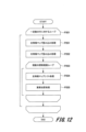
これまでに説明した動作例1では、コスト算出部30によるマッチングコスト算出処理(P103)において、画像全体に対して1度にコストマップを生成する場合に関して説明したが、次に説明する図12のフローチャートに示す処理のように、部分領域毎に処理を実行することもできる。
すなわち、図12に示すように、マッチングコスト算出処理(P301)では、連続した一定数の行に対して、図5のフローチャートに示すP201~P205の処理と同一の処理を実行する。一定数の行に対して行われる個々の処理(P201、P202、P203、P204、P205)は、図5で説明した通りである。
コスト算出部30は、P201~P205の処理を一定数の行毎に繰り返すことで、最終的なコストマップを生成する。
コスト算出部30は、P201~P205の処理を一定数の行毎に繰り返すことで、最終的なコストマップを生成する。
このように、コスト算出部30は、連続した一定数の行毎にコストマップを生成し、処理する領域を分割することで、使用するメモリ量を低減することができる。また、コスト算出部30は、分散して推論できる実行環境の場合に、連続した一定数の行毎に分散して推論し、その結果を統合することで、推論時間を短縮することができる。
なお、これまで説明した(動作例1)の特徴抽出処理(P102)では、入力画像のサイズと出力される特徴マップのサイズが等しい想定であった。一方で、特徴抽出部20は、入力画像のサイズに比べて出力される特徴マップのサイズを小さくすることもできる。
特徴抽出部20は、畳み込みニューラルネットワーク(N100)において、畳み込み演算部21によりストライド2以上の畳み込み演算を実行することで入力画像に比べて小さいサイズの特徴マップを出力することができる。
例えば、畳み込み演算部21によりストライド2の畳み込みを2回実行することで出力される特徴マップは、入力画像の1/4のサイズとなる。すなわち、出力された特徴マップの1pixが、入力画像における4pixに相当する。この場合において、コスト算出部30は、入力画像に対する視差の探索範囲が64pixであった場合、その1/4に対応した16pix回数のコスト算出処理をマッチングコスト算出処理(P103)で実行する。このように、本実施の形態例の特徴抽出処理によれば、様々なサイズの特徴マップを出力する構成に変更することができる。
また、これまで説明した(動作例1)のコスト補正処理(P104)では、入力されたコストマップと同一サイズのコストマップを出力する想定で処理を説明したが、入力されたコストマップに比べて大きいコストマップを出力したり、小さいコストマップを出力したりするように変更することもできる。
具体的には、入力に比べて大きいコストマップを出力する場合には、畳み込みニューラルネットワーク(N200)において、畳み込み演算部41は、エンコードに利用したストライド数に比べて大きなストライドをデコード時に設定することで、大きいサイズの特徴マップを出力できる。入力に比べて小さいコストマップを出力する場合には、畳み込みニューラルネットワーク(N200)において、畳み込み演算部41は、エンコードに利用したストライド数に比べて小さなストライドをデコード時に設定することで、小さいサイズの特徴マップを出力できる。
具体的には、入力に比べて大きいコストマップを出力する場合には、畳み込みニューラルネットワーク(N200)において、畳み込み演算部41は、エンコードに利用したストライド数に比べて大きなストライドをデコード時に設定することで、大きいサイズの特徴マップを出力できる。入力に比べて小さいコストマップを出力する場合には、畳み込みニューラルネットワーク(N200)において、畳み込み演算部41は、エンコードに利用したストライド数に比べて小さなストライドをデコード時に設定することで、小さいサイズの特徴マップを出力できる。
また、図8~図11に示す処理を利用して、学習時に決定した3次元畳み込みカーネルを、推論時に統合して利用する方法を説明したが、畳み込み演算の横方向と視差方向のパディングの影響を考慮し、以下のように変更してもよい。
以降の説明では、3次元畳み込みカーネルのサイズが幅、高さ、奥行方向それぞれ3pixであると想定する。
すなわち、コスト算出部30は、学習時において左右特徴マップのペアを生成する際に、右特徴マップ(F101)の左右端を1pixずつ削る。そして、コスト算出部30は、右特徴マップ(F101)のサイズをWR-2とする。その後、コスト算出部30は、左特徴マップ(F100)と右特徴マップ(F101)のペアを生成する。これにより、左特徴マップのサイズはWL=WR+Dであるため、D+3個のペアが生成される。その後、コスト算出部30は、D+3個のペアに対して3次元畳み込み処理を実行する。そして、コスト算出部30は、出力したコストマップの幅方向に対して左右端1pixずつ、奥行方向に対しては最小と最大の1枚ずつの特徴マップを削る。
これにより出力される特徴マップのサイズは、(D+1、WR-4、H)となる。推論時では、コスト算出部30は、入力の右特徴マップ(F101)の左右端を1pixずつ削り、右特徴マップ(F101)のサイズをWR-2とする。その後、コスト算出部30は、右特徴マップ(F101)と左特徴マップ(F100)に対して、統合したカーネルを利用してそれぞれ畳み込み演算を実行する。
そして、コスト算出部30は、右特徴マップ(F111)の左右端1pixずつをさらに削り、右特徴マップ(F111)のサイズをWR-4とする。その後、コスト算出部30は、左特徴マップ(F110)の左右端2pixずつをさらに削り、左特徴マップ(F110)のサイズをWL=WR+D―4とする。そして、コスト算出部30は、要素加算処理を実行することで、(D+1、WR-4、H)のコストマップを生成する。このようにすることで、コスト算出部30は、学習時においてパディングの影響を受けるコストマップを推論時に除外することができ、画像端や視差の最大値・最小値まで、学習時と推論時の演算結果を一致させることができる。
そして、コスト算出部30は、右特徴マップ(F111)の左右端1pixずつをさらに削り、右特徴マップ(F111)のサイズをWR-4とする。その後、コスト算出部30は、左特徴マップ(F110)の左右端2pixずつをさらに削り、左特徴マップ(F110)のサイズをWL=WR+D―4とする。そして、コスト算出部30は、要素加算処理を実行することで、(D+1、WR-4、H)のコストマップを生成する。このようにすることで、コスト算出部30は、学習時においてパディングの影響を受けるコストマップを推論時に除外することができ、画像端や視差の最大値・最小値まで、学習時と推論時の演算結果を一致させることができる。
[環境認識装置が行う処理の動作例2:単眼カメラを利用してフローを算出する例]
次に、環境認識装置1が行う動作例2として、単眼カメラで撮像された複数時刻の画像から同一被写体の画素の移動量を表現したフロー(オプティカルフロー)を算出する動作について説明する。
以降では、単眼カメラで撮像された時刻T-1の画像と、その直後の時刻Tの画像の2枚を利用して、時刻Tから時刻T-1へのフローを算出する処理動作に関して説明する。
また、フローの最大値・最小値は、縦方向と横方向で±3pixであり、時刻Tの対象画素において7×7の画素の領域内でフローを算出する処理として説明する。
次に、環境認識装置1が行う動作例2として、単眼カメラで撮像された複数時刻の画像から同一被写体の画素の移動量を表現したフロー(オプティカルフロー)を算出する動作について説明する。
以降では、単眼カメラで撮像された時刻T-1の画像と、その直後の時刻Tの画像の2枚を利用して、時刻Tから時刻T-1へのフローを算出する処理動作に関して説明する。
また、フローの最大値・最小値は、縦方向と横方向で±3pixであり、時刻Tの対象画素において7×7の画素の領域内でフローを算出する処理として説明する。
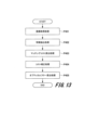
図13は、本実施の形態例における動作例2のフロー算出における処理を示す。
フローの算出では、画像取得処理(P401)、特徴抽出処理(P402)、マッチングコスト算出処理(P403)、コスト補正処理(P404)、及びオプティカルフロー算出処理(P405)が順に実行される。
まず、画像取得処理(P401)において、画像取得部10は、時刻T-1と時刻Tに撮像された2枚の画像を取得する。
特徴抽出処理(P402)では、特徴抽出部20は、画像取得処理(P401)で取得された時刻T-1に撮像された画像と時刻Tに撮像された画像のそれぞれに対して、畳み込みニューラルネットワークを利用してそれぞれの画像から特徴マップを生成する。
フローの算出では、画像取得処理(P401)、特徴抽出処理(P402)、マッチングコスト算出処理(P403)、コスト補正処理(P404)、及びオプティカルフロー算出処理(P405)が順に実行される。
まず、画像取得処理(P401)において、画像取得部10は、時刻T-1と時刻Tに撮像された2枚の画像を取得する。
特徴抽出処理(P402)では、特徴抽出部20は、画像取得処理(P401)で取得された時刻T-1に撮像された画像と時刻Tに撮像された画像のそれぞれに対して、畳み込みニューラルネットワークを利用してそれぞれの画像から特徴マップを生成する。
図4に示した視差算出における特徴抽出処理との違いは、特徴抽出部20が左右の画像ではなく、時刻T-1と時刻Tの2枚の画像に対して特徴マップをそれぞれ算出する点である。また、畳み込みニューラルネットの畳み込み処理で利用されるカーネルは、後述する学習により推定される。
マッチングコスト算出処理(P403)では、コスト算出部30は、特徴抽出処理(P402)で取得された時刻T-1の特徴マップF201と時刻Tの特徴マップF200を利用して、各フローに対するコストを算出する。
マッチングコスト算出処理(P403)では、コスト算出部30は、特徴抽出処理(P402)で取得された時刻T-1の特徴マップF201と時刻Tの特徴マップF200を利用して、各フローに対するコストを算出する。
図14は、コスト算出部30によるマッチングコスト算出処理(P403)を示すフローチャートである。
コスト算出部30は、マッチングコスト算出処理(P403)において、時刻T-1の特徴マップ畳み込み処理(P201′)、時刻T特徴マップ畳み込み処理(P202′)を実施する。そして、コスト算出部30は、候補フローに対応したコスト算出を各フロー候補数(7×7)だけ実行する(P203)。時刻T-1の特徴マップ畳み込み処理(P201′)と、時刻T特徴マップ畳み込み処理(P202′)は、それぞれ図5で説明した左画像特徴マップ畳み込み処理(P201)と、右画像特徴マップ畳み込み処理(P202)の画像が、それぞれ時刻T-1の画像と時刻Tの画像に変わるだけである。
コスト算出部30は、マッチングコスト算出処理(P403)において、時刻T-1の特徴マップ畳み込み処理(P201′)、時刻T特徴マップ畳み込み処理(P202′)を実施する。そして、コスト算出部30は、候補フローに対応したコスト算出を各フロー候補数(7×7)だけ実行する(P203)。時刻T-1の特徴マップ畳み込み処理(P201′)と、時刻T特徴マップ畳み込み処理(P202′)は、それぞれ図5で説明した左画像特徴マップ畳み込み処理(P201)と、右画像特徴マップ畳み込み処理(P202)の画像が、それぞれ時刻T-1の画像と時刻Tの画像に変わるだけである。
候補フローに対応したコスト算出(P203)では、コスト算出部30は、時刻T-1の特徴マップを、候補フロー分だけシフトさせる(P204)。その後、コスト算出部30は、シフトされた時刻T-1の特徴マップと時刻Tの特徴マップを、要素加算処理を行うことで当該フローに対するコストを算出する(P205)。コスト算出部30は、この候補フローに対応したコスト算出(P203)を、探索範囲で繰り返し実行する。
図15は、コスト算出部30による図13のマッチングコスト算出処理(P403)の処理手順を示す。
コスト算出部30は、時刻T-1特徴マップF201に対して、畳み込みパラメータK(T-1)を利用した畳み込み演算C(T-1)を実行し、時刻T-1特徴マップF211を算出する。また、コスト算出部30は、時刻Tにおける特徴マップF200に対して、畳み込みパラメータK(T)を利用した畳み込み演算C(T)を実行し、時刻Tにおける特徴マップF210を算出する。その後、コスト算出部30は、候補フローである(-3,-3)~(3,3)に対して、コストを算出する。そして、コスト算出部30は、候補フロー(-3,-3)に関するコスト生成において、時刻T特徴マップF210に対して、時刻T-1特徴マップF211を左方向に3pix、上方向に3pixシフトさせ、要素加算処理を実行する。
コスト算出部30は、時刻T-1特徴マップF201に対して、畳み込みパラメータK(T-1)を利用した畳み込み演算C(T-1)を実行し、時刻T-1特徴マップF211を算出する。また、コスト算出部30は、時刻Tにおける特徴マップF200に対して、畳み込みパラメータK(T)を利用した畳み込み演算C(T)を実行し、時刻Tにおける特徴マップF210を算出する。その後、コスト算出部30は、候補フローである(-3,-3)~(3,3)に対して、コストを算出する。そして、コスト算出部30は、候補フロー(-3,-3)に関するコスト生成において、時刻T特徴マップF210に対して、時刻T-1特徴マップF211を左方向に3pix、上方向に3pixシフトさせ、要素加算処理を実行する。
コスト算出部30は、以上の処理を、(-3,-3)~(3,3)の範囲で順に実行し、各候補フローに対応したコストを算出し、それぞれのコストを奥行方向に連結することでコストマップC200を生成する。コストマップ(C200)の各位置には、フロー候補に応じたコストが格納される。
これまでの説明では、説明の都合上、特徴マップのチャンネルに関して記載しなかったが、各特徴マップは、チャンネル方向にサイズを持っている。また、動作例1の視差算出で説明したのと同様に、コストマップC200はチャンネル毎にコストが格納されている。また、時刻Tにおける特徴マップF210と時刻T-1における特徴マップF211の要素加算処理において、コスト算出部30は、時刻T-1における特徴マップF211をシフトする。これにより、時刻Tにおける特徴マップF210と時刻T-1における特徴マップF211は、重なることがなくなり、要素加算処理ができない場合がある。そのため、特徴抽出部20は、コスト算出部30において要素加算処理ができなくなることを防ぐために、特徴抽出処理(P402)において時刻T-1の画像は、時刻Tの画像に比べて広い範囲を指定して入力される。
コスト集約部40によるコスト補正処理(P404)では、マッチングコスト算出処理(P403)で算出されたコストマップC200に対して、畳み込み演算部41において、図7に示すように畳み込み処理を実行することで周辺領域を考慮したコストマップが生成される。
オプティカルフロー算出処理(P405)では、コスト補正処理(P404)で補正したコストマップに対して、コスト解析部51が実行する畳み込み演算により、(H、W、2)のサイズとなる特徴マップが生成される。H、Wは特徴マップの高さと幅をそれぞれ示しており、各位置に対して、フローの座標(横方向フロー、縦方向フロー)が格納されている。
オプティカルフロー算出処理(P405)では、コスト補正処理(P404)で補正したコストマップに対して、コスト解析部51が実行する畳み込み演算により、(H、W、2)のサイズとなる特徴マップが生成される。H、Wは特徴マップの高さと幅をそれぞれ示しており、各位置に対して、フローの座標(横方向フロー、縦方向フロー)が格納されている。
以上説明したように、図13に示す特徴抽出処理(P402)、マッチングコスト算出処理(P403)、コスト補正処理(P404)、及びオプティカルフロー算出処理(P405)では、学習により決定されたカーネルを利用して畳み込み演算が実行される。
次に、この場合の学習方法に関して説明する。
この学習方法では、オプティカルフロー算出処理(P405)で算出したフローに対してロス関数が定義され、定義されたロス関数が最小化される。ロス関数は、横方向フローと縦方向フローそれぞれに対して、正解値データの横方向フローと縦方向フローとの差の絶対値を計算する。したがって、横方向フローと縦方向フローの差の絶対値を加算したものが画素毎の誤差となる。この誤差は、正解値データが格納された画素だけ計算され、その平均した値がロス関数として利用される。
この学習方法では、オプティカルフロー算出処理(P405)で算出したフローに対してロス関数が定義され、定義されたロス関数が最小化される。ロス関数は、横方向フローと縦方向フローそれぞれに対して、正解値データの横方向フローと縦方向フローとの差の絶対値を計算する。したがって、横方向フローと縦方向フローの差の絶対値を加算したものが画素毎の誤差となる。この誤差は、正解値データが格納された画素だけ計算され、その平均した値がロス関数として利用される。
以上説明したように、本実施の形態例の環境認識装置1は、フロー算出におけるマッチングコスト算出において、時刻Tの画像と時刻T-1の画像に対して1度だけ畳み込み演算を実行するだけで、フローに対するコスト算出を実施できるようになる。したがって、各フロー候補に対する3次元畳み込み演算を実施する場合に比べて、演算量を低減することができる。
なお、ここまで説明した動作例2では、学習時により決定したカーネルを推論時のマッチングコスト算出処理(P403)で利用するようにした。
一方、以下に説明する処理に基づいて、学習により決定したカーネルを統合したものをマッチングコスト算出処理(P403)で利用することもできる。すなわち、学習時と推論時で演算方法を変更する構成にすることができる。また、次に説明する処理により推論時に利用するカーネルを生成することで、学習時の構成と同一の出力結果を得ることができる。
一方、以下に説明する処理に基づいて、学習により決定したカーネルを統合したものをマッチングコスト算出処理(P403)で利用することもできる。すなわち、学習時と推論時で演算方法を変更する構成にすることができる。また、次に説明する処理により推論時に利用するカーネルを生成することで、学習時の構成と同一の出力結果を得ることができる。
図16は、学習時におけるマッチングコスト算出処理(P403)を示す。
コスト算出部30は、候補フロー毎に時刻Tにおける特徴マップF200と時刻T-1における特徴マップF201で特徴マップのペアを作成する。具体的には、コスト算出部30は、候補フロー(-3、-3)に関しては、時刻Tにおける特徴マップF200に対して時刻T-1における特徴マップF201を左方向に3pixシフトさせ、上方向に3pixシフトさせて、特徴マップペアF(-3,-3)を作成する。
コスト算出部30は、この手続きを各候補フローに対応した回数実行することで、F(-3,-3)~F(3,3)を生成する。その後、コスト算出部30は、生成した特徴マップペアF(-3,-3)~F(3,3)を奥行方向に連結し、3次元畳み込みカーネル(K100)を利用して畳み込み演算を実行する。この際に利用する3次元畳み込みカーネル(K100)は、(49,3,3)のサイズを持つ。すなわち、3次元畳み込みカーネル(K100)は、空間方向に対しては3x3のサイズになり、奥行方向に対してはすべての特徴アップペアF(-3,-3)~F(3,3)に対して畳み込み可能なサイズになる。
推論時には、コスト算出部30では、学習時に利用した3次元畳み込みカーネル(K100)が統合され、利用される。図15に示した畳み込みパラメータK(T-1)、及び畳み込みパラメータK(T)が推論時に利用される統合されたカーネルである。統合の方法は、基本的には動作例1と類似した手続きとなる。
具体的には、コスト算出部30は、畳み込みパラメータK(T)としては、3次元畳み込みカーネル(K100)のうち、時刻Tにおける特徴マップF200に対するそれぞれのカーネルを要素加算することで、畳み込みパラメータK(T)を生成する。また、コスト算出部30は、畳み込みパラメータK(T-1)に関しては、3次元畳み込みカーネル(K100)のうち、時刻T-1における特徴マップF201に対するそれぞれのカーネルを利用する。
具体的には、コスト算出部30は、畳み込みパラメータK(T)としては、3次元畳み込みカーネル(K100)のうち、時刻Tにおける特徴マップF200に対するそれぞれのカーネルを要素加算することで、畳み込みパラメータK(T)を生成する。また、コスト算出部30は、畳み込みパラメータK(T-1)に関しては、3次元畳み込みカーネル(K100)のうち、時刻T-1における特徴マップF201に対するそれぞれのカーネルを利用する。
ここで、コスト算出部30は、特徴マップペアF(0,0)に対するカーネルに対して、F(-3,-3)~F(3,3)に対するカーネルを要素加算するが、その際にF(-3,-3)~F(3,3)をシフトして要素加算する。コスト算出部30は、F(-3,-3)を要素加算する場合には、カーネルを左方向に3pix、上方向に3pixシフトして要素加算を実行する。
以上の処理を、すべてのカーネルに対して実行することで、コスト算出部30は、畳み込みパラメータK(T-1)を生成する。動作例1との違いは、左右方向のみにカーネルをシフトするだけでなく、上下方向にもカーネルをシフトする点である。
以上の処理を、すべてのカーネルに対して実行することで、コスト算出部30は、畳み込みパラメータK(T-1)を生成する。動作例1との違いは、左右方向のみにカーネルをシフトするだけでなく、上下方向にもカーネルをシフトする点である。
本実施の形態例の環境認識装置1では、学習時に求めた3次元畳み込みカーネルが、推論時には統合され、2次元畳み込みカーネルとして利用される。このようにすることで、3次元畳み込みカーネルを利用して学習されたモデルを、推論時において再学習することなく、より少ない演算量で実行することができる。また、学習時に利用する3次元畳み込みカーネルのパラメータ数と推論時に利用するパラメータ数を比較した場合、推論時に利用するパラメータ数の方が少なくなる。これにより、より少ないメモリ使用量で視差算出を実行することが可能になる。
[変形例]
以上、実施の形態例による動作例1および動作例2で本発明を説明したが、本発明は上述した実施の形態例に限定されるものではない。
例えば、上述した実施の形態例では、コスト集約部40を有する構成とした。これに対して、コスト集約部40を有さずに、視差もしくはフローを算出してもよい。
以上、実施の形態例による動作例1および動作例2で本発明を説明したが、本発明は上述した実施の形態例に限定されるものではない。
例えば、上述した実施の形態例では、コスト集約部40を有する構成とした。これに対して、コスト集約部40を有さずに、視差もしくはフローを算出してもよい。
例えば動作例1では、ステレオカメラの左右画像のうち、右画像に対応した視差算出を実行したが、左画像に対応した視差算出にも利用できる。
また動作例2では、単眼カメラの時刻T-1の画像と時刻Tの画像に対応したフローの算出を実行したが、時刻T-1より前のさらに別の時刻T―2の画像と時刻Tの画像のフローを算出してもよい。すなわち、動作例2は、任意のフレーム間のフローの算出に適用が可能である。
また、特徴抽出部(P102)、マッチングコスト算出処理(P103)、コスト補正処理(P104)の処理において、図で説明したネットワーク構造やカーネルのサイズは具体的な一例を示したまでであり、上述した構造、もしくはサイズ以外であってもよい。
また動作例2では、単眼カメラの時刻T-1の画像と時刻Tの画像に対応したフローの算出を実行したが、時刻T-1より前のさらに別の時刻T―2の画像と時刻Tの画像のフローを算出してもよい。すなわち、動作例2は、任意のフレーム間のフローの算出に適用が可能である。
また、特徴抽出部(P102)、マッチングコスト算出処理(P103)、コスト補正処理(P104)の処理において、図で説明したネットワーク構造やカーネルのサイズは具体的な一例を示したまでであり、上述した構造、もしくはサイズ以外であってもよい。
また、ここまで説明した各実施の形態例は、本発明を分かりやすく説明するために詳細に説明したものであり、必ずしも説明した全ての構成を備えるものに限定されるものではない。
また、本発明の適用例として図2に示した車両に搭載したカメラが撮影した画像から環境認識して、車両制御を行う点についても一例であり、その他の車両などの各種移動体に搭載したカメラから環境認識する場合に適用してもよい。環境認識結果を使う用途についても、車両制御に限定されない。
また、図1および図2に示す構成図では、制御線や情報線は説明上必要と考えられるものだけを示しており、製品上必ずしも全ての制御線や情報線を示しているとは限らない。
実際には殆ど全ての構成が相互に接続されていると考えてもよい。
また、図3などに示すフローチャートの動作処理の流れについても一例であり、処理結果が同じであれば、一部の処理順序を変えたり、複数の処理を同時に実行したりしてもよい。
また、本発明の環境認識装置内で行われる処理は、プログラム(ソフトウェア)の実行により行われるものであり、例えば既存のコンピュータ(情報処理装置)に、実施の形態例で説明した処理を実行するプログラムを実装することで、本発明の環境認識装置として機能させてもよい。この場合のプログラムの情報は、メモリや、ハードディスク、SSD(Solid State Drive)、ICカード、SDカード光ディスク等の各種記録媒体に置くことができる。
また、環境認識装置は、図2に示す構成では、CPUの制御で実行されるコンピュータで構成した例としたが、環境認識装置が行う機能の一部又は全部を、FPGA(Field Programmable Gate Array)やASIC(Application Specific Integrated Circuit)などの専用のハードウェアによって実現してもよい。
また、環境認識装置は、図2に示す構成では、CPUの制御で実行されるコンピュータで構成した例としたが、環境認識装置が行う機能の一部又は全部を、FPGA(Field Programmable Gate Array)やASIC(Application Specific Integrated Circuit)などの専用のハードウェアによって実現してもよい。
1…環境認識装置、2…車両制御装置、3L…車載カメラ、4…コンピュータ、4a…CPU、4b…ワークメモリ、4c…記憶部、4d…インターフェース、5…車両、10…画像取得部、11…画像格納部、12…画像格納部、20…特徴抽出部、21…畳み込み演算部、22…特徴抽出パラメータ格納部、30…コスト算出部、31…画像畳み込み演算部、32…画像畳み込み演算部、33…パラメータ格納部、34…パラメータ格納部、35…統合部、40…コスト集約部、41…畳み込み演算部、42…特徴抽出パラメータ格納部、50…マッチング部、51…コスト解析部
Claims (10)
- 第一の画像と第二の画像を取得する画像取得部と、
前記第一の画像の複数の部分領域に対して特徴量を求めることによって得られる第一の特徴マップと、前記第二の画像の複数の部分領域に対して特徴量を求めることによって得られる第二の特徴マップと、を求める特徴抽出部と、
前記第一の特徴マップおよび前記第二の特徴マップに対して畳み込み演算を行うことで各部分領域の対応関係に関する確からしさを表現したマッチングコストを求めるコスト算出部と、
前記コスト算出部で求めたマッチングコストを解析することで第一の画像と第二の画像の対応関係を確定させるマッチング部と、を備え、
前記コスト算出部は、前記第一の特徴マップと前記第二の特徴マップのそれぞれに対して、コスト算出用の第一のパラメータと第二のパラメータを利用した畳み込み演算を実行することで第一の畳み込み演算結果と第二の畳み込み演算結果をそれぞれ求め、前記第一の畳み込み演算結果と前記第二の畳み込み演算結果とを統合することで前記マッチングコストを求める
環境認識装置。 - 前記第一の画像と前記第二の画像は、それぞれ第一のカメラと第二のカメラにより同時刻に取得された画像であり、
前記マッチング部で確定される対応関係は視差である
請求項1に記載の環境認識装置。 - 前記コスト算出部は、前記第一の畳み込み演算結果と前記第二の畳み込み演算結果とを統合する際に、前記第一の畳み込み演算結果と前記第二の畳み込み演算結果とのいずれか一方を左右方向にずらして要素加算する
請求項2に記載の環境認識装置。 - 前記第一の画像と前記第二の画像は、一つのカメラにより異なる時刻に取得された画像であり、
前記マッチング部で確定される対応関係は移動量を表現したフローである
請求項1に記載の環境認識装置。 - 前記コスト算出部は、前記第一の畳み込み演算結果と前記第二の畳み込み演算結果とを統合する際に、前記第一の畳み込み演算結果と前記第二の畳み込み演算結果とのいずれか一方を上下左右方向にずらして要素加算する
請求項4に記載の環境認識装置。 - 前記コスト算出部において、前記コスト算出用の第一のパラメータと前記コスト算出用の第二のパラメータは、学習時に推定した畳み込みパラメータを統合したものである
請求項1に記載の環境認識装置。 - 前記コスト算出用の第一のパラメータと前記コスト算出用の第二のパラメータとのいずれか一方は、前記学習時に推定した畳み込みパラメータの一部を要素加算したものであり、
前記コスト算出用の第一のパラメータと前記コスト算出用の第二のパラメータとのもう一方は、前記学習時に推定した畳み込みパラメータの一部を空間方向にずらして要素加算したものである
請求項6に記載の環境認識装置。 - 前記コスト算出部は、一定数の行毎に前記マッチングコストを算出する
請求項1に記載の環境認識装置。 - 前記マッチングコストを補正するコスト集約部を備え、
前記マッチング部は、前記コスト集約部が補正した前記マッチングコストに対して対応関係を確定させる
請求項1~8のいずれか1項に記載の環境認識装置。 - 第一の画像と第二の画像を取得する画像取得処理と、
前記第一の画像の複数の部分領域に対して特徴量を求めることによって得られる第一の特徴マップと、前記第二の画像の複数の部分領域に対して特徴量を求めることによって得られる第二の特徴マップと、を求める特徴抽出処理と、
前記第一の特徴マップおよび前記第二の特徴マップに対して畳み込み演算を行うことで各部分領域の対応関係に関する確からしさを表現したマッチングコストを求めるコスト算出処理と、
前記コスト算出処理により求めたマッチングコストを解析することで第一の画像と第二の画像の対応関係を確定させるマッチング処理と、を含み、
前記コスト算出処理では、前記第一の特徴マップと前記第二の特徴マップのそれぞれに対して、コスト算出用の第一のパラメータと第二のパラメータを利用した畳み込み演算を実行することで第一の畳み込み演算結果と第二の畳み込み演算結果をそれぞれ求め、前記第一の畳み込み演算結果と前記第二の畳み込み演算結果とを統合することで前記マッチングコストを求める
環境認識方法。
Priority Applications (1)
| Application Number | Priority Date | Filing Date | Title |
|---|---|---|---|
| DE112023001011.0T DE112023001011T5 (de) | 2022-06-10 | 2023-05-31 | Umgebungserkennungsvorrichtung und Umgebungserkennungsverfahren |
Applications Claiming Priority (2)
| Application Number | Priority Date | Filing Date | Title |
|---|---|---|---|
| JP2022094052A JP7796596B2 (ja) | 2022-06-10 | 2022-06-10 | 環境認識装置および環境認識方法 |
| JP2022-094052 | 2022-06-10 |
Publications (1)
| Publication Number | Publication Date |
|---|---|
| WO2023238751A1 true WO2023238751A1 (ja) | 2023-12-14 |
Family
ID=89118331
Family Applications (1)
| Application Number | Title | Priority Date | Filing Date |
|---|---|---|---|
| PCT/JP2023/020282 Ceased WO2023238751A1 (ja) | 2022-06-10 | 2023-05-31 | 環境認識装置および環境認識方法 |
Country Status (3)
| Country | Link |
|---|---|
| JP (1) | JP7796596B2 (ja) |
| DE (1) | DE112023001011T5 (ja) |
| WO (1) | WO2023238751A1 (ja) |
Citations (3)
| Publication number | Priority date | Publication date | Assignee | Title |
|---|---|---|---|---|
| JP2008204102A (ja) * | 2007-02-19 | 2008-09-04 | Yokohama National Univ | 画像処理システム |
| JP2019139420A (ja) * | 2018-02-08 | 2019-08-22 | 株式会社リコー | 立体物認識装置、撮像装置および車両 |
| JP2022064388A (ja) * | 2020-10-14 | 2022-04-26 | 日立Astemo株式会社 | 物体認識装置 |
Family Cites Families (1)
| Publication number | Priority date | Publication date | Assignee | Title |
|---|---|---|---|---|
| CN109887019B (zh) | 2019-02-19 | 2022-05-24 | 北京市商汤科技开发有限公司 | 一种双目匹配方法及装置、设备和存储介质 |
-
2022
- 2022-06-10 JP JP2022094052A patent/JP7796596B2/ja active Active
-
2023
- 2023-05-31 DE DE112023001011.0T patent/DE112023001011T5/de active Pending
- 2023-05-31 WO PCT/JP2023/020282 patent/WO2023238751A1/ja not_active Ceased
Patent Citations (3)
| Publication number | Priority date | Publication date | Assignee | Title |
|---|---|---|---|---|
| JP2008204102A (ja) * | 2007-02-19 | 2008-09-04 | Yokohama National Univ | 画像処理システム |
| JP2019139420A (ja) * | 2018-02-08 | 2019-08-22 | 株式会社リコー | 立体物認識装置、撮像装置および車両 |
| JP2022064388A (ja) * | 2020-10-14 | 2022-04-26 | 日立Astemo株式会社 | 物体認識装置 |
Also Published As
| Publication number | Publication date |
|---|---|
| DE112023001011T5 (de) | 2025-01-02 |
| JP7796596B2 (ja) | 2026-01-09 |
| JP2023180611A (ja) | 2023-12-21 |
Similar Documents
| Publication | Publication Date | Title |
|---|---|---|
| US11422546B2 (en) | Multi-modal sensor data fusion for perception systems | |
| Esparza et al. | The STDyn-SLAM: A stereo vision and semantic segmentation approach for VSLAM in dynamic outdoor environments | |
| US5777690A (en) | Device and method for detection of moving obstacles | |
| JP5782088B2 (ja) | 歪みのあるカメラ画像を補正するシステム及び方法 | |
| US12225839B2 (en) | Crop row guidance systems | |
| US7295684B2 (en) | Image-based object detection apparatus and method | |
| KR20210025942A (ko) | 종단간 컨볼루셔널 뉴럴 네트워크를 이용한 스테레오 매칭 방법 | |
| Rasib et al. | Pixel level segmentation based drivable road region detection and steering angle estimation method for autonomous driving on unstructured roads | |
| US20120002866A1 (en) | Method and apparatus for reducing the memory requirement for determining disparity values for at least two stereoscopically recorded images | |
| US20140362289A1 (en) | Method and apparatus for increasing frame rate of an image stream using at least one higher frame rate image stream | |
| CN119540518A (zh) | 图像和视频中的实时显著目标检测 | |
| JP7148462B2 (ja) | 画像認識評価プログラム、画像認識評価方法、評価装置及び評価システム | |
| US20170316570A1 (en) | Image processing apparatus and method | |
| JP2024521816A5 (ja) | ||
| Gkillas et al. | An efficient deep unrolling super-resolution network for lidar automotive scenes | |
| Park et al. | Improvement of optical flow estimation by using the hampel filter for low-end embedded systems | |
| WO2018143277A1 (ja) | 画像特徴量出力装置、画像認識装置、画像特徴量出力プログラム、及び画像認識プログラム | |
| US10078902B1 (en) | Fast robust method for compensating ego-translations and detecting independent moving objects in video captured with a moving camera | |
| Leng et al. | Occupancy learning with spatiotemporal memory | |
| US10060740B2 (en) | Distance detection device | |
| JP7796596B2 (ja) | 環境認識装置および環境認識方法 | |
| Gupta et al. | Diffusion-FS: Multimodal Free-Space Prediction via Diffusion for Autonomous Driving | |
| JP7206602B2 (ja) | 撮像装置、車両、及び撮像方法 | |
| Munger et al. | How many features is an image worth? multi-channel cnn for steering angle prediction in autonomous vehicles | |
| JP7801206B2 (ja) | 画像認識装置、保存画像決定方法 |
Legal Events
| Date | Code | Title | Description |
|---|---|---|---|
| 121 | Ep: the epo has been informed by wipo that ep was designated in this application |
Ref document number: 23819731 Country of ref document: EP Kind code of ref document: A1 |
|
| WWE | Wipo information: entry into national phase |
Ref document number: 112023001011 Country of ref document: DE |
|
| 122 | Ep: pct application non-entry in european phase |
Ref document number: 23819731 Country of ref document: EP Kind code of ref document: A1 |