WO2023238350A1 - 無人航空機の運航支援システム及び運航支援方法 - Google Patents
無人航空機の運航支援システム及び運航支援方法 Download PDFInfo
- Publication number
- WO2023238350A1 WO2023238350A1 PCT/JP2022/023363 JP2022023363W WO2023238350A1 WO 2023238350 A1 WO2023238350 A1 WO 2023238350A1 JP 2022023363 W JP2022023363 W JP 2022023363W WO 2023238350 A1 WO2023238350 A1 WO 2023238350A1
- Authority
- WO
- WIPO (PCT)
- Prior art keywords
- unmanned aircraft
- span
- flight
- wind conditions
- flight plan
- Prior art date
- Legal status (The legal status is an assumption and is not a legal conclusion. Google has not performed a legal analysis and makes no representation as to the accuracy of the status listed.)
- Ceased
Links
Images


Classifications
-
- B—PERFORMING OPERATIONS; TRANSPORTING
- B64—AIRCRAFT; AVIATION; COSMONAUTICS
- B64C—AEROPLANES; HELICOPTERS
- B64C13/00—Control systems or transmitting systems for actuating flying-control surfaces, lift-increasing flaps, air brakes, or spoilers
- B64C13/02—Initiating means
- B64C13/16—Initiating means actuated automatically, e.g. responsive to gust detectors
- B64C13/20—Initiating means actuated automatically, e.g. responsive to gust detectors using radiated signals
-
- B—PERFORMING OPERATIONS; TRANSPORTING
- B64—AIRCRAFT; AVIATION; COSMONAUTICS
- B64C—AEROPLANES; HELICOPTERS
- B64C39/00—Aircraft not otherwise provided for
- B64C39/02—Aircraft not otherwise provided for characterised by special use
-
- G—PHYSICS
- G01—MEASURING; TESTING
- G01C—MEASURING DISTANCES, LEVELS OR BEARINGS; SURVEYING; NAVIGATION; GYROSCOPIC INSTRUMENTS; PHOTOGRAMMETRY OR VIDEOGRAMMETRY
- G01C21/00—Navigation; Navigational instruments not provided for in groups G01C1/00 - G01C19/00
- G01C21/26—Navigation; Navigational instruments not provided for in groups G01C1/00 - G01C19/00 specially adapted for navigation in a road network
- G01C21/34—Route searching; Route guidance
-
- H—ELECTRICITY
- H02—GENERATION; CONVERSION OR DISTRIBUTION OF ELECTRIC POWER
- H02G—INSTALLATION OF ELECTRIC CABLES OR LINES, OR OF COMBINED OPTICAL AND ELECTRIC CABLES OR LINES
- H02G1/00—Methods or apparatus specially adapted for installing, maintaining, repairing or dismantling electric cables or lines
- H02G1/02—Methods or apparatus specially adapted for installing, maintaining, repairing or dismantling electric cables or lines for overhead lines or cables
Definitions
- the present invention relates to an unmanned aircraft operation support system and an operation support method.
- unmanned aerial vehicles such as drones
- power equipment such as power transmission lines
- Patent Document 1 describes a power transmission line inspection system using an unmanned aerial vehicle configured to automatically inspect trees approaching power lines.
- the above-mentioned power transmission line inspection system is an unmanned helicopter that is equipped with a flight control system for flying autonomously to inspection points on power lines and an information collection system for collecting various information including images of inspection points and distance measurement data.
- a control center equipped with a flight control/information collection system that controls the flight of the unmanned helicopter and collects and processes various information from the unmanned helicopter, and images and distances of inspection points collected by the unmanned helicopter's information collection system.
- An approaching tree inspection means for creating a three-dimensional image from the measurement data, processing the created three-dimensional image, and checking whether there is an abnormality in the power transmission line at the inspection point based on the processed three-dimensional image; and a storage device storing various data used for inspection by the approaching tree inspection means.
- Unmanned aircraft are easily affected by wind during flight, and it is especially difficult to maintain their posture during strong winds. Therefore, conventionally, mechanisms have been proposed to formulate a flight plan after accurately grasping or accurately predicting the weather conditions for the flight plan before or during the flight.
- Patent Document 2 describes a weather observation system and a flight control system configured for the purpose of safely flying an unmanned aircraft.
- the above-mentioned weather observation system allows a drone to fly in a vertical direction almost directly above or in a vertical direction directly below, and measures wind direction and wind speed from control information of the flying drone.
- the above flight control system acquires information on wind direction and wind speed related to the flight plan by flying the first drone, and selects a flight plan for the second drone by referring to the information on the wind direction and wind speed. do.
- Patent Document 3 describes an unmanned aircraft management device configured for the purpose of ensuring the safety of unmanned aircraft.
- the unmanned aircraft management device acquires the scheduled flight route of the unmanned aircraft, acquires weather information that specifies the weather at the scheduled flight time in an area including the acquired scheduled flight route, and based on the scheduled flight route and the weather information, Predict the actual flight path of an unmanned aircraft.
- Power transmission lines and distribution lines are often installed in areas with locally varying wind conditions (wind direction, wind speed), such as mountainous areas and other hilly areas.
- wind direction wind direction
- wind speed wind speed
- Patent Document 2 the wind direction and wind speed are measured from the control information of the drone in flight, but the drone needs to fly almost vertically above or vertically below each time the measurement is performed. This consumes extra power and fuel and reduces flight time for patrols and inspections.
- Patent Document 3 uses weather information provided by the Japan Meteorological Agency and information measured by observation equipment such as wind condition sensors, so it is not possible to obtain local wind conditions for each span. .
- observation equipment such as wind condition sensors are generally expensive and require various preparations and work, such as securing a power source, installing communication equipment, and regular maintenance and replacement.
- the present invention was made in view of this background, and provides an unmanned aircraft operation support system and an unmanned aircraft operation support system that can efficiently acquire local wind conditions and support the safe operation of unmanned aircraft.
- the purpose is to provide a navigation support method.
- One of the means for solving the above problems is an unmanned aircraft operation support system that is configured using an optical analysis unit, an information processing device, and a communication device that wirelessly communicates with the unmanned aircraft, and is Obtaining the current wind conditions in the span of the power transmission line or distribution line based on the vibration state obtained by DAS (Distributed Acoustic Sensing) at measurement points set along the optical fiber installed along the electric wire, A flight plan is generated based on the acquired wind conditions, and the generated flight plan or a flight control instruction based on the flight plan is transmitted to the unmanned aircraft.
- DAS Distributed Acoustic Sensing
- FIG. 1 is a diagram showing a schematic configuration of a navigation support system.
- FIG. 3 is a diagram illustrating a mechanism for measuring a vibration state. This is an example of time series data of measured values (parallel direction). This is an example of time series data of measured values (orthogonal direction). This is an example of a differential prediction formula (parallel direction). This is an example of a differential prediction formula (orthogonal direction). This is an example of time series data of predicted values (parallel direction). This is an example of time series data of predicted values (orthogonal direction).
- 1 is a diagram showing the main configuration of a wind condition information providing device.
- FIG. 2 is a diagram illustrating the main functions of the wind condition information providing device.
- FIG. 2 is a diagram illustrating the main functions of the flight control device.
- 1 is a diagram showing the main configuration of an unmanned aircraft.
- FIG. 2 is a diagram illustrating the main functions of an unmanned aircraft. It is a flowchart explaining flight control processing.
- FIG. 1 shows a schematic configuration of an unmanned aircraft operation support system (hereinafter referred to as "operation support system 1") described as an embodiment of the present invention.
- the navigation support system 1 includes a wind condition information providing device 100 installed at a substation 6, etc., and an overhead power transmission line installed on a power transmission tower 2 (a distribution line installed on a utility pole etc. may also be used).
- An unmanned aerial vehicle 200 (drone) that performs duties such as patrolling and inspecting power equipment (power transmission towers 2, power transmission lines 3, substation equipment 4, etc.) by flying along power transmission lines (hereinafter referred to as "power transmission lines 3").
- an operation control device 300 which is an information processing device that communicates with the unmanned aircraft 200, monitors the unmanned aircraft 200, provides various information, controls the operation, etc.
- the wind condition information providing device 100 uses an optical fiber 4a of an OPGW4 (optical ground wire) installed on a power transmission line 3 as a sensor, and detects multiple points (hereinafter referred to as , each point is referred to as a "measurement point.")
- a technique for measuring the vibration state (vibration intensity, vibration frequency) based on the expansion and contraction of the optical fiber 4a (distributed multipoint vibration measurement method (hereinafter referred to as "DAS”)).
- DAS distributed multipoint vibration measurement method
- the wind conditions (wind direction, wind speed) at each measurement point are acquired based on the vibration state of each measurement point.
- the vibration state of each measurement point is acquired using the principle of Domain Reflectometer.
- FIG. 2 is a diagram illustrating how the wind condition information providing device 100 measures the vibration state of each measurement point.
- the wind condition information providing apparatus 100 inputs a light pulse (laser pulse; hereinafter also referred to as "incident light”) from the end face of an optical fiber 4a, and Measure the rate of change in the phase difference of scattered light ( ⁇ stretching frequency). Note that the above phase difference is estimated from intensity changes due to interference between backscattered lights. Then, the wind condition information providing device 100 determines the vibration frequencies of the longitudinal waves and transverse waves of the optical fiber 4a at each measurement point (for example, vibration frequencies in a maximum range of 10 kHz) based on the measured rate of change.
- a light pulse laser pulse
- ⁇ stretching frequency the rate of change in the phase difference of scattered light
- the wind condition information providing device 100 determines the vibration intensity (spectral intensity, vibration amplitude) at each measurement point based on the phase difference for each vibration frequency. Note that the wind condition information providing device 100 determines the position of each measurement point (distance from the end surface) based on the elapsed time from the time when the incident light enters the end surface to the time when the returned light is received.
- the above measurement points are set, for example, at predetermined intervals d (m) shorter than the span of the power transmission tower 2 along the optical fiber (0 (m), d (m), ..., N (m), N+d(m), N+2d(m)). For example, if the predetermined interval d is 5 (m) and measurement points are set in a range of up to 70 (km), about 14,000 measurement points are set along the optical fiber.
- the wind condition information providing device 100 acquires the vibration state of each span of the power transmission line 3 (between adjacent power transmission towers 2) based on the vibration state of each measurement point.
- Non-Patent Document 1 Search on vibration characteristics of power transmission lines during strong winds", Urban Disaster Management, Ken Inayoshi, Kyushu University, List of master's theses, URL: https://www.hues.kyushu-u .ac.jp/education/student/pdf/2003/2HE02019E.pdf (searched on May 18, 2020)
- the vibration state of the optical fiber 4a in the span is There is a certain correlation with wind conditions.
- the wind condition of the span can be obtained.
- the vibration mode (natural vibration mode) of the vibration state of the optical fiber 4a differs depending on the wind speed (the vibration state becomes nonlinear with respect to changes in wind speed), so the above statistical model is generated for each range of wind speed (for example, , a statistical model for the case where the wind speed is less than 3 (m/s) and a statistical model for the case where the wind speed is 3 (m/s) or more are prepared respectively).
- the characteristics of the vibration state of the optical fiber 4a differ from span to span due to differences in the span length and the installation state of the OPGW 4, the above statistical model is generated for each span.
- the predetermined interval d (m) is shorter than the span of the transmission tower 2
- multiple measurement points are included in one span.
- the method of acquiring the status is not necessarily limited.
- the wind condition at the measurement point with the highest wind speed among the plurality of measurement points or the average value of the wind conditions at each measurement point may be used as the wind condition for the span.
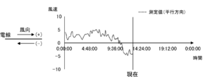
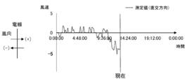
- the wind condition information providing device 100 calculates the direction along the optical fiber 4a (direction of longitudinal waves; direction of extension of the optical fiber 4a; hereinafter referred to as " The wind velocity components (respectively referred to as “parallel direction components", (referred to as the “orthogonal direction component”), and the wind conditions (wind direction, wind speed) of the span are determined based on the obtained parallel direction component and orthogonal direction component.
- FIG. 3A shows an example of time-series data of the parallel direction component (hereinafter referred to as “measured value (parallel direction)”) in a certain span, obtained by the wind condition information providing apparatus 100 as described above.
- FIG. 3B shows an example of time-series data of the orthogonal direction component (hereinafter referred to as “measured value (orthogonal direction)”) in the above span, which is obtained by the wind condition information providing apparatus 100.
- the horizontal axis of the graph shown in each figure is time, and the vertical axis is wind speed (m/s).
- the wind condition information providing device 100 provides (sends) the current wind condition of the span determined as above to the flight control device 300. Further, the wind condition information providing device 100 predicts the future wind conditions of the span using the time series data of the wind conditions of the span obtained as described above, and controls the operation of the predicted wind conditions of the span. Provide (send) to the device 300.
- the wind condition information providing device 100 calculates the above forecast based on the scheduled flight area (scheduled flight airspace) of the unmanned aircraft 200, which is obtained from weather information obtained from a weather information providing organization such as the Japan Weather Association (registered trademark). Forecast values (actual values may also be used) of the target wind conditions over a wider range than the wind conditions for each span in a predetermined area near the power equipment that the unmanned aerial vehicle 200 is to patrol or inspect, etc. This is done by making corrections using the wind conditions obtained for the span. Specifically, the wind condition information providing device 100 first obtains time-series data of the wind conditions in the span obtained as described above (hereinafter referred to as "first time-series data") and weather information.
- first time-series data time-series data of the wind conditions in the span obtained as described above
- Approximate expression that expresses the correlation between the difference between the predicted wind condition value (actual value may also be used) and time series data (hereinafter referred to as "second time series data") and the value of the second time series data.
- second time series data time series data
- a linear approximation formula Hereinafter referred to as a “difference prediction formula.”
- the wind condition information providing device 100 predicts the future wind condition of the span by reflecting (adding) the difference obtained from the above-mentioned difference prediction formula to the predicted value of the wind condition obtained from the weather information. .
- the wind condition information providing device 100 is based on a database (for example, an equipment information database (equipment ledger database) managed by an administrator of power equipment such as an electric power company) that shows the installation status of the power transmission tower 2 and the power transmission line 3.
- a database for example, an equipment information database (equipment ledger database) managed by an administrator of power equipment such as an electric power company) that shows the installation status of the power transmission tower 2 and the power transmission line 3.
- a database for example, an equipment information database (equipment ledger database) managed by an administrator of power equipment such as an electric power company) that shows the installation status of the power transmission tower 2 and the power transmission line 3.
- a database for example, an equipment information database (equipment ledger database) managed by an administrator of power equipment such as an electric power company) that shows the installation status of the power transmission tower 2 and the power transmission line 3.
- Mutual conversion between wind conditions for each span determined as parallel and orthogonal components and wind conditions expressed in absolute direction (absolute direction with north as 0° (360°)
- FIG. 4A shows an example of a difference prediction formula for the parallel direction component of wind speed (hereinafter referred to as “difference prediction formula (parallel direction)").
- FIG. 4B shows an example of a difference prediction formula for orthogonal direction components of wind speed (hereinafter referred to as “difference prediction formula (orthogonal direction)").
- Fig. 5A shows that the difference calculated from the difference prediction formula (parallel direction) is reflected in the parallel direction forecast value of wind conditions (hereinafter referred to as “forecast value (parallel direction)”) obtained from weather information (
- forecast value (parallel direction) An example of time series data of a future parallel direction component (hereinafter referred to as “predicted value (parallel direction)") predicted by adding (addition) is shown below.
- FIG. 5B shows that the difference obtained from the differential prediction formula (orthogonal direction) is reflected (added) to the forecast value of wind conditions obtained from weather information (hereinafter referred to as “forecast value (orthogonal direction)").
- predicted values (orthogonal directions) An example of time-series data of future orthogonal direction components (hereinafter referred to as “predicted values (orthogonal directions)" predicted by this method is shown below.
- the flight control device 300 transmits the real-time wind conditions for each span and predicted values (future wind conditions) of the wind conditions received from the wind condition information providing device 100 to the unmanned aircraft 200 at any time.
- the flight control device 300 also updates the flight plan of the unmanned aircraft 200 and controls the flight of the unmanned aircraft 200 based on real-time wind conditions and predicted values of wind conditions (future wind conditions) for each span.
- a flight plan includes, for example, a flight route (including information such as departure point, stopover point, destination, flight altitude, etc.), departure date and time, time and date of transit points, date and time of arrival at destination, Includes flight time, possible flight time, remaining battery power (remaining amount of onboard fuel if the power unit is an internal combustion engine), identification markings, unmanned aircraft model, payload information, information on the person in charge of operation, etc.
- FIG. 6A is a diagram showing the main configuration of the wind condition information providing device 100.
- the wind condition information providing device 100 includes a processor 101, a main storage device 102 (memory), an auxiliary storage device 103 (external storage device), an input device 104, an output device 105, a communication device 106, and an optical An analysis unit 107 is provided. These are communicably connected via a bus, communication cable, or the like.
- the wind condition information providing apparatus 100 may be realized, in whole or in part, using virtual information processing resources, such as a virtual server provided by a cloud system.
- the processor 101 is, for example, a CPU (Central Processing Unit), MPU (Micro Processing Unit), GPU (Graphics Processing Unit), FPGA (Field Programmable Gate Array), ASIC (Application Specific Integrated Circuit), AI (Artificial Intelligence) chip, etc. It is configured using
- the main storage device 102 is a storage device used when the processor 101 executes a program, and includes, for example, ROM (Read Only Memory), RAM (Random Access Memory), nonvolatile memory (NVRAM (Non Volatile RAM)), etc. It is.
- the auxiliary storage device 103 is a device that stores programs and data, and includes, for example, an SSD (Solid State Drive), a hard disk drive, an optical storage device (CD (Compact Disc), DVD (Digital Versatile Disc), etc.). can do. Programs and data can be read into the auxiliary storage device 103 from a non-temporary recording medium or another information processing device equipped with a non-temporary storage device via a recording medium reading device or a communication device 106. . Programs and data stored in the auxiliary storage device 103 are read into the main storage device 102 at any time.
- an SSD Solid State Drive
- CD Compact Disc
- DVD Digital Versatile Disc
- the input device 104 is an interface that accepts input of information from the outside, and is, for example, a keyboard, mouse, touch panel, voice input device, etc.
- the output device 105 is an interface that outputs various information such as processing progress and processing results to the outside.
- the output device 105 is, for example, a display device that visualizes the above various information (liquid crystal monitor, LCD (Liquid Crystal Display), etc.), a device that converts the above various information into audio (sound output device (speaker, etc.)), It is a device (printing device, etc.) that converts various information into characters. Note that, for example, a configuration may be adopted in which the information processing device 10 inputs and outputs information to and from another device via the communication device 106.
- the input device 104 and the output device 105 constitute a user interface that realizes interaction processing (receiving information, providing information, etc.) with the user.
- the communication device 106 is a device that realizes communication with other devices via a communication network (LAN (Local Area Network), WAN (Wide Area Network), Internet, public communication network, dedicated line, etc.).
- the communication device 106 is a wired or wireless communication interface that realizes communication with other devices via a communication medium, and is, for example, a NIC (Network Interface Card), a wireless communication module, a USB module, etc. be.
- NIC Network Interface Card
- the optical analysis unit 107 is a device that measures the vibration state of a measurement point using DAS, and includes a vibration measurement device using C-OTDR and a signal processing circuit.
- the optical analysis unit 107 includes a CW (continuous wave) laser light source that generates optical pulses (laser light) input to the end face of the optical fiber 4a, an optical pulse generator, an optical amplifier, and optical equipment (optical detector, optical interference device). , including a signal processing circuit (phase calculation circuit, etc.).
- the optical analysis unit 107 and the optical fiber 4a are connected, for example, by optically connecting the emitting part of the laser light source of the optical analysis unit 107 to a connection port (socket) of the core wire of an OPGW provided in the substation. This is done by Therefore, there will be no impact on the power system, such as a power outage, when the connection is made.
- an operating system a file system, a DBMS (DataBase Management System) (relational database, NoSQL, etc.), a KVS (Key-Value Store), etc. may be installed in the wind condition information providing device 100.
- DBMS DataBase Management System
- NoSQL NoSQL
- KVS Key-Value Store
- wind condition information providing apparatus 100 can be performed by the processor 101 reading and executing programs stored in the main storage device 102, or by using the hardware (FPGA) constituting the wind condition information providing apparatus 100. , ASIC, AI chip, etc.) itself.
- the wind condition information providing device 100 stores various information (data) as, for example, a database table or a file managed by a file system.
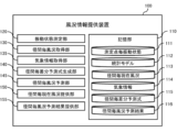
- FIG. 6B is a block diagram illustrating the main functions of the wind condition information providing device 100.
- the wind condition information providing device 100 includes a storage section 110, a vibration state measuring section 120, a span-specific wind condition acquisition section 130, a weather information acquisition section 135, a span-specific difference prediction formula generation section 140, It includes the functions of a span-by-span wind condition prediction section 145, a span-by-span current wind condition provision section 150, and a span-by-span wind condition prediction result provision section 155.
- the storage unit 110 stores vibration conditions for each measurement point 111, statistical models 112, current wind conditions for each span 113, weather information 114, difference prediction formulas for each span 115, and wind condition prediction results for each span 116. remember.
- the vibration state measurement unit 120 measures the vibration state of each measurement point using DAS, and manages the vibration state (vibration intensity, vibration frequency) measured for each measurement point as a vibration state 111 for each measurement point.
- the span-by-span wind condition acquisition unit 130 obtains the vibration state for each span of the power transmission line 3 (between adjacent transmission towers 2) (the vibration state for each measurement point in each span) based on the vibration state at each measurement point.
- the wind conditions for each span are obtained by inputting the obtained vibration state into the corresponding statistical model 112 (the above-mentioned statistical model generated for each wind speed range and each span).
- the span-by-span wind condition acquisition unit 130 manages the acquired wind condition time-series data (first time-series data) as the span-by-span current wind condition 113.
- the weather information acquisition unit 135 acquires weather information (latest weather information, past weather information) used for predicting wind conditions for each span via a communication network such as the Internet, from a website such as the Japan Weather Association (registered trademark). Obtained from weather information providers as needed.
- the weather information covers a wider area than the current wind conditions for each span in a predetermined area near the power equipment that the unmanned aerial vehicle 200 is to patrol or inspect in the area where the unmanned aerial vehicle 200 is scheduled to fly. Contains wind conditions and forecast values for wind conditions.
- the weather information acquisition unit 135 manages the acquired weather information as the weather information 114. Furthermore, the weather information acquisition unit 135 mutually converts the wind conditions in each span obtained as parallel direction components and orthogonal direction components to the wind conditions expressed in absolute azimuth.
- the span-by-span difference prediction formula generation unit 140 generates the above-described difference prediction formulas (difference prediction formula (parallel direction), difference prediction formula (orthogonal direction)) for each span.
- the per-span difference prediction formula generation unit 140 manages the generated difference prediction formula for each span (for each measurement point) as a per-span difference prediction formula 115 .
- the span-by-span wind condition prediction unit 145 reflects the difference obtained by the above-mentioned difference prediction formula (difference prediction formula (parallel direction), difference prediction formula (orthogonal direction)) to the wind condition forecast value obtained from the weather information. By doing so, the wind conditions for each span can be predicted.
- the span-by-span wind condition prediction unit 145 manages the predicted wind conditions for each span as a span-by-span wind condition prediction result 116.
- the current wind condition provision unit 150 for each span provides (sends) the current wind condition 113 for each span managed by the wind condition acquisition unit 130 for each span to the flight control device 300.
- the span-by-span wind condition prediction result providing unit 155 provides (sends) the span-by-span wind condition prediction result 116 managed by the span-by-span wind condition prediction unit 145 to the flight control device 300.
- the OPGW 4 optical fiber 4a
- the wind conditions for each altitude are calculated by converting the current wind conditions for each span 113 and the predicted wind conditions for each span 116, taking into account the influence of the wind gradient.
- the determined wind conditions for each altitude may be provided to the flight control device 300.
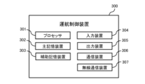
- FIG. 7A is a diagram showing the main configuration of the flight control device 300.
- the flight control device 300 includes a processor 301, a main storage device 302 (memory), an auxiliary storage device 303 (external storage device), an input device 304, an output device 305, a communication device 306, and a wireless communication device. 307. These are communicably connected via a bus, communication cable, or the like.
- the processor 301, the main storage device 302, the auxiliary storage device 303, the input device 304, the output device 305, and the communication device 306 are the processor 101, the main storage device 102, and the communication device 306 of the wind condition information providing device 100, respectively. Since they are the same as the auxiliary storage device 103, input device 104, output device 105, and communication device 106, their explanation will be omitted.
- the wireless communication device 307 includes a wireless communication module that performs analog or digital wireless communication using radio waves of a predetermined frequency, and transmits and receives various information to and from the unmanned aircraft 200.
- the wireless communication device 307 also uses a telemetering mechanism to provide information about the unmanned aircraft 200 (for example, various sensors (satellite positioning device, acceleration sensor, speed sensor, geomagnetic sensor, microwave radar, microwave radar, LiDAR (Light)). Detection And Ranging), measured values of an EKF device (extended Kalman filter), images or video captured by a camera mounted on the unmanned aerial vehicle 200) are acquired at any time (in real time, at scheduled times, at scheduled times, etc.).
- the flight control device 300 stores various information (data) as, for example, a database table or a file managed by a file system.
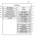
- FIG. 7B is a block diagram illustrating the main functions of the flight control device 300.
- the operation control device 300 includes a storage unit 310, a current wind condition acquisition unit for each span 320, a prediction result acquisition unit for wind conditions for each span 330, a current wind condition transmission unit for each span 335, a current wind condition transmission unit for each span 335, and a current wind condition transmission unit for each span.
- Each function of the wind condition prediction result transmission section 340, unmanned aircraft information acquisition section 345, flight plan management section 350, flight plan transmission section 355, flight control instruction transmission section 360, other system cooperation section 365, and flight monitoring section 370 Be prepared.
- the storage unit 310 stores current wind conditions for each span 311, wind condition prediction results for each span 312, flight plans 313, unmanned aircraft information 314, flight control instructions 315, and other system acquisition information 316. .
- the span-specific current wind condition acquisition unit 320 receives the span-specific current wind condition 113 sent from the wind condition information providing device 100, and converts the span-specific current wind condition 113 into the span-specific current wind condition 311. Manage as.
- the span-by-span wind condition prediction result acquisition unit 330 receives the span-by-span wind condition prediction result 116 sent from the wind condition information providing device 100, and acquires the span-by-span wind condition prediction result 116 from the span-by-span wind condition prediction result. It is managed as a situation prediction result 312.
- the current wind condition transmission unit for each span 335 transmits the current wind condition for each span 311 to the unmanned aircraft 200.
- the span-by-span wind condition prediction result transmitting unit 340 transmits the span-by-span wind condition prediction result 312 to the unmanned aircraft 200.
- the unmanned aircraft information acquisition unit 345 receives information regarding the current situation of the unmanned aircraft 200 (current position, acceleration, speed, flight direction, flight attitude, remaining battery power, photographed image or photographed video, etc.), and transmits the received information. It is managed as unmanned aircraft information 314.
- the flight plan management unit 350 manages the flight plan set for the unmanned aircraft 200 as a flight plan 313.
- the flight plan management section 35 receives information necessary for setting the flight plan 313, for example, via the other system cooperation section 365 or the user interface, and formulates (generates) a flight plan based on the received information.
- the flight plan management unit 35 also receives the current wind conditions for each span 311, the predicted wind conditions for each span 312, the unmanned aircraft information 314, and information provided from the other system cooperation unit 365 (for example, information obtained by rain cloud radar, etc.).
- a flight plan 313 is drawn up in consideration of the weather information for each region.
- the flight plan management unit 35 receives the wind condition prediction results for each span 312, the unmanned aircraft information 314, and information provided from the other system cooperation unit 365 (for example, weather information for each region acquired by rain cloud radar etc.)
- the flight plan 313 is updated from time to time in consideration of the above.
- the flight plan management unit 35 determines whether the unmanned aircraft 200 is safe based on the current wind conditions 311 for each span, weather information provided from the other system cooperation unit 365 (other system acquisition information 316), and unmanned aircraft information 314. Wind conditions that would affect the flight (wind conditions that deviate from the operational limits set for the unmanned aircraft 200) or weather conditions that are currently being encountered, or wind conditions that would affect safe flight if the flight continues. If it is determined that there is a possibility of encountering a situation or weather, the flight plan 313 is changed to a flight plan 313 that allows the unmanned aircraft 200 to fly safely (a flight plan that selects a flight route that does not deviate from operational restrictions). .
- the flight plan management unit 35 may create a flight plan 313 that can avoid the other aircraft. etc., the flight plan 313 is changed to a flight plan 313 that allows the unmanned aircraft 200 to fly safely.
- the unmanned aircraft 200 is currently encountering wind conditions or weather conditions that would impede safe flight, or if it continues to fly as it is, there is a possibility that it will encounter wind conditions or weather conditions that would impair safe flight.
- the wind speed exceeds a preset limit value at which the unmanned aircraft 200 can fly (for example, the limit value of the wind speed acting on the unmanned aircraft 200 in flight (wind resistance, operational limit)) (or In other cases, if the flight continues to the destination, the battery level may fall below the lower limit required for the flight.
- the flight plan 313 that allows safe flight includes, for example, a flight plan in which the flight distance does not exceed the cruising range determined from the relationship between the current wind conditions, predicted wind conditions, and the current battery level;
- the flight plan management unit 350 may accept corrections to the changed flight plan from the user, for example, via a user interface. Further, for example, the flight plan management unit 350 may apply the changed flight plan to the actual flight of the unmanned aircraft 200 after receiving the user's intention to approve the changed flight plan via the user interface. Good too.
- the flight plan management unit 350 takes into account the current battery level and current or future wind conditions based on the current wind conditions for each span 311, the predicted wind conditions for each span 312, and the unmanned aircraft information 314. The possible flight distance and flight time in that case may be determined, and the determined results may be presented to the user via a user interface. Further, the flight plan management unit 350 may notify (transmit) the obtained result to the unmanned aircraft 200.
- the flight plan transmitting unit 355 shown in FIG. 7B transmits the flight plan 313 to the unmanned aircraft 200 at any time.
- the flight control instruction transmitting unit 360 also provides flight control instructions for the unmanned aircraft 200 based on, for example, the current wind conditions for each span 311, the predicted wind conditions for each span 312, the unmanned aircraft information 314, and the latest flight plan 313. 315 and transmits the generated flight control instruction 315 to the unmanned aircraft 200.
- the other system cooperation unit 365 communicates with other systems (for example, an operation management system operated by NEDO (registered trademark) (New Energy and Industrial Technology Development Organization), a weather information providing organization, etc.), and Information that should be referred to when creating a plan 313 or generating flight control instructions 315 (flight plans and flight restriction information for other aircraft (unmanned aircraft and manned aircraft), etc.) and the latest weather information (current weather information for each region, etc.) Get (receive) the latest forecast).
- the other system cooperation unit 365 manages the acquired information as other system acquisition information 316.
- the other system cooperation unit 365 transmits information regarding the operation of the unmanned aircraft 200 (for example, current wind conditions for each span 311, predicted wind conditions for each span 312, flight plan 313, unmanned aircraft information 314, etc.) to other systems. Provide (send) information from time to time. By providing this information to other systems, the accuracy of the information provided by the flight management system can be improved, and the safety of aircraft operations can be increased.
- information regarding the operation of the unmanned aircraft 200 for example, current wind conditions for each span 311, predicted wind conditions for each span 312, flight plan 313, unmanned aircraft information 314, etc.
- the flight monitoring unit 370 compares the most recently acquired unmanned aircraft information 314 with the flight plan 313 and monitors the flight status of the unmanned aircraft 200 and whether the flight according to the flight plan 313 has been completed.
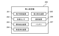
- FIG. 8A is a diagram showing the main configuration of the unmanned aircraft 200.
- the unmanned aircraft 200 includes a flight control system 201 (FCS: Flight Control System, FCU: Flight Control Unit), various sensors 202, an inertial navigation device 203 (EKF: Extended Kalman Filter), and a satellite positioning device 204. , a thrust generator 205, a communication device 206, and a battery 207.
- FCS Flight Control System
- FCU Flight Control Unit
- EKF Extended Kalman Filter
- the flight control device 201 is configured using an information processing device such as a microcomputer, and controls the flight and various operations of the unmanned aircraft 200.
- the various sensors 202 are, for example, an acceleration sensor, a speed sensor, a geomagnetic sensor, a microwave radar, a microwave radar, a LiDAR, an EKF device, a camera, etc.
- the inertial navigation device 203 determines the current position by performing self-position estimation processing (for example, self-position estimation processing using an extended Kalman filter) based on information (acceleration, angular velocity, etc.) measured in real time by various sensors 202. Output the current position.
- self-position estimation processing for example, self-position estimation processing using an extended Kalman filter
- information acceleration, angular velocity, etc.
- the satellite positioning device 204 uses a satellite positioning system such as GNSS (Global Navigation Satellite System) to obtain the current position by independent positioning or relative positioning (D-GPS positioning, RTK (Real Time Kinematic), etc.). It is a device that receives positioning signals sent from positioning satellites such as GPS satellites, calculates the current position, and inputs the calculated current position to the flight control device 201.
- GNSS Global Navigation Satellite System
- RTK Real Time Kinematic
- the thrust generator 205 includes a power motor and a motor control device (ESC: Electronic Speed Controller).
- ESC Electronic Speed Controller
- the communication device 206 performs bidirectional wireless communication with the flight control device 300.
- the battery 207 is, for example, a lithium ion polymer secondary battery, and supplies driving power to each component of the unmanned aircraft 200.
- FIG. 8B is a block diagram illustrating the main functions of the unmanned aircraft 200.
- the unmanned aircraft 200 includes a storage unit 210, an aircraft information transmitting unit 220, a flight plan receiving unit 230, a flight control instruction receiving unit 235, a current wind condition receiving unit 240 for each span, and a wind condition receiving unit 240 for each span. It has the functions of a prediction result receiving section 245 and a flight control section 250.
- the storage unit 210 stores aircraft information 211 (current position information 2111 (latitude, longitude, altitude), flight speed/acceleration information 2112, flight course information 2113, remaining battery level information 2114, payload information) acquired in real time about the unmanned aircraft 200. 2115), a flight plan 216, flight control instructions 217, current wind conditions for each span 218, and predicted wind conditions for each span 219.
- aircraft information 211 current position information 2111 (latitude, longitude, altitude), flight speed/acceleration information 2112, flight course information 2113, remaining battery level information 2114, payload information
- 2115 a flight plan 216
- flight control instructions 217 current wind conditions for each span 218, and predicted wind conditions for each span 219.
- the aircraft information transmitting unit 220 transmits the aircraft information 211 to the flight control device 300 at any time (in real time, on schedule, at scheduled time, etc.). Note that the aircraft information 211 transmitted by the aircraft information transmitter 220 to the flight control device 300 is managed as unmanned aircraft information 314 in the flight control device 300.
- the flight plan receiving unit 230 receives the flight plan 313 sent from the flight control device 300 and manages the received flight plan 313 as a flight plan 216.
- the flight control instruction receiving unit 235 receives the flight control instruction 315 sent from the flight control device 300 and manages the received flight control instruction 315 as a flight control instruction 217.
- the current wind condition for each span receiving unit 240 receives the current wind condition for each span 311 sent from the flight control device 300, and manages the received current wind condition for each span 311 as the current wind condition for each span 218. do.
- the span-by-span wind condition prediction result receiving unit 245 receives the span-by-span wind condition prediction result 312 sent from the flight control device 300, and converts the received span-by-span wind condition prediction result 312 into a span-by-span wind condition prediction result. It is managed as a result 219.
- the flight control unit 250 uses a remote control method to passively control the flight of the unmanned aircraft 200 according to the flight control instruction 217 from the operation control device 300, or autonomously controls the flight of the unmanned aircraft 200 based on the aircraft information 211.
- the flight of the unmanned aircraft 200 is controlled by one of the autonomous control methods.
- the flight control unit 250 controls the flight of the unmanned aircraft 200 according to the flight plan 216.
- the flight control instruction 217 can be given priority over the flight plan 216, and in that case, upon receiving the flight control instruction 217, the flight control unit 250 controls the flight of the unmanned aircraft 200 according to the received flight control instruction 217. control.
- the flight control unit 250 controls the flight of the unmanned aircraft 200 based on, for example, the current wind conditions for each span 218 and the predicted wind conditions for each span 219. For example, the flight control unit 250 determines, based on the current wind conditions 311 for each span and the unmanned aircraft information 314, that the unmanned aircraft 200 is currently encountering wind conditions that are suitable for safe flight, or that the unmanned aircraft 200 continues to fly. If it is determined that there is a possibility that the unmanned aerial vehicle 200 will encounter wind conditions that would impede safe flight, the unmanned aerial vehicle 200 is controlled to select a flight path or flight speed that allows the unmanned aerial vehicle 200 to fly safely. do.
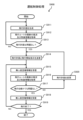
- FIG. 9 is a flowchart illustrating an example of a process (hereinafter referred to as "operation control process S900") performed by the flight control device 300 during operation of the unmanned aircraft 200.
- operation control process S900 will be described below with reference to the same figure.
- the flight plan management unit 350 of the flight control device 300 generates the flight plan 313 (S911).
- the current wind condition acquisition unit 320 for each span of the flight control device 300 obtains the latest wind conditions for the flight route in the flight plan 313 (wind conditions for the spans along the flight route (current wind conditions for each span 311, The span-by-span wind condition prediction result 312)) is acquired from the wind condition information providing device 100, and the other system cooperation unit 365 of the flight control device 300 acquires the latest weather information from other systems (S912).
- the flight plan management unit 350 of the flight control device 300 determines whether there is any problem with the flight plan 313 drawn up in S911 (whether a safe flight can be ensured) based on the acquired wind conditions and weather information (S913 ). If there is a problem with the flight plan 313 drawn up in S911 (S913: NO), the process returns to S911, and the flight plan management unit 350 reconsiders the flight plan 313 while taking into account the acquired wind conditions and weather information. If there is no problem with the flight plan 313 drawn up in S911 (S913: YES), the process proceeds to S914.
- the flight plan transmitting unit 355 of the operation control device 300 transmits the flight plan 313 created in S911 and the flight control instruction 315 according to the flight plan 313 to the unmanned aircraft 200.
- the unmanned aircraft information acquisition unit 345 of the flight control device 300 receives unmanned aircraft information 314 from the unmanned aircraft 200 at any time (S915).
- the current wind condition acquisition unit 320 for each span of the flight control device 300 also acquires the latest wind conditions for the flight route in the flight plan 313 (wind conditions for the spans along the flight route (current wind conditions for each span 311, current wind conditions for each span 311, The hourly wind condition prediction result 312)) is acquired from the wind condition information providing device 100, and the other system cooperation unit 365 of the flight control device 300 acquires the latest weather information for the flight planned area from other systems (S916). ).
- the flight plan management unit 350 of the operation control device 300 determines whether the unmanned aircraft 200 is flying safely and whether it can maintain a safe flight even if it continues to fly. (S917) is whether the current situation exceeds or is likely to exceed the wind speed of the unmanned aircraft 200, whether there is enough remaining battery power to reach the destination, etc. (S917). If it is determined that a safe flight cannot be maintained (S917: NO), the flight plan management unit 350 reconsiders the flight plan 313 in consideration of the acquired wind conditions and weather information (S920), and then the process returns to S914. . On the other hand, if the flight plan management unit 350 determines that a safe flight can be maintained (S917: YES), the process proceeds to S918.
- the unmanned aircraft information acquisition unit 345 receives the latest unmanned aircraft information 314 from the unmanned aircraft 200.
- the flight monitoring unit 370 of the unmanned aircraft 200 compares the latest unmanned aircraft information 314 with the flight plan 313, and determines whether the flight of the unmanned aircraft 200 has ended (the flight according to the flight plan 313 has been completed). Determine. If the flight monitoring unit 370 determines that the flight of the unmanned aircraft 200 has not ended (S919: NO), the process returns to S915. On the other hand, if the flight monitoring unit 370 determines that the flight of the unmanned aircraft 200 has ended (S919: YES), the operation control process S900 ends.
- the unmanned aircraft 200 may perform all or part of the functions of the flight control processing S900 described above. Further, in the above, the flight control device 300 acquires weather information from other systems, but the flight control device 300 may acquire weather information from the wind condition information providing device 100.
- the navigation support system 1 of the present embodiment measures the diameter of the power transmission line 3 based on the vibration state acquired by DAS at measurement points set along the optical fiber attached along the power transmission line.
- a flight plan is generated based on the acquired wind conditions, and the generated flight plan or a flight control instruction based on the flight plan is transmitted to the unmanned aircraft 200. Therefore, the local wind conditions in the span can be efficiently acquired.
- the flight support system 1 since the flight support system 1 generates a flight plan based on the local wind conditions at the site where the unmanned aircraft 200 actually flies, the flight support system 1 generates a flight plan based only on the weather information provided by a weather information provider, etc. It is possible to generate a flight plan based on highly accurate wind conditions that reflect the effects of the topography of the site. Therefore, the unmanned aircraft 200 can be operated safely.
- the navigation support system 1 calculates future forecasts based on the correlation between past time-series data of forecast values of wind conditions provided by weather information providing organizations and past time-series data of wind conditions in spans. By correcting the values, the future wind conditions of the span are predicted, and a flight plan is generated based on the predicted wind conditions. Therefore, local wind conditions in the span of the power transmission line 3 can be predicted efficiently. Furthermore, since the flight support system generates a flight plan based on predicted values of local wind conditions at the site where the unmanned aircraft 200 actually flies, the flight plan is generated based only on weather information provided by a weather information provider. Compared to the case of generating a flight plan, it is possible to generate a flight plan based on highly accurate wind conditions that reflect the influence of the topography of the site. Therefore, the unmanned aircraft 200 can be operated safely.
- the flight support system 1 selects a flight route that does not deviate from the operational limits and generates a flight plan. Therefore, the unmanned aircraft 200 can be operated safely.
- the flight support system 1 generates a flight plan based on the possible cruising distance determined from the relationship between the current or predicted wind conditions and the remaining battery power. Therefore, a flight plan can be appropriately generated within the cruising range, and the unmanned aircraft 200 can be operated safely.
- 1 Operation support system 2 Power transmission tower, 3 Power transmission line, 4 OPGW, 4a Optical fiber, 6 Substation, 100 Wind condition information providing device, 107 Optical analysis unit, 110 Storage unit, 111 Vibration status for each measurement point, 112 Statistical model , 113 Current wind condition for each span, 114 Weather information, 115 Difference prediction formula for each span, 116 Wind condition prediction result for each span, 120 Vibration condition measurement unit, 130 Wind condition acquisition unit for each span, 135 Weather information acquisition unit , 140 Span-specific difference prediction formula generation unit, 145 Span-specific wind condition prediction unit, 150 Span-specific current wind condition provision unit, 155 Span-specific wind condition prediction result provision unit, 200 Unmanned aerial vehicle, 210 Storage unit, 211 Aircraft information, 2114 Battery remaining information, 216 Flight plan, 217 Flight control instructions, 218 Current wind conditions for each span, 219 Wind condition prediction results for each span, 230 Flight plan receiving section, 235 Flight control instruction receiving section, 240 Radius Current wind condition reception unit for each span, 2
Landscapes
- Engineering & Computer Science (AREA)
- Radar, Positioning & Navigation (AREA)
- Remote Sensing (AREA)
- Automation & Control Theory (AREA)
- Aviation & Aerospace Engineering (AREA)
- Physics & Mathematics (AREA)
- General Physics & Mathematics (AREA)
- Traffic Control Systems (AREA)
Priority Applications (2)
| Application Number | Priority Date | Filing Date | Title |
|---|---|---|---|
| PCT/JP2022/023363 WO2023238350A1 (ja) | 2022-06-09 | 2022-06-09 | 無人航空機の運航支援システム及び運航支援方法 |
| JP2022554522A JPWO2023238350A1 (https=) | 2022-06-09 | 2022-06-09 |
Applications Claiming Priority (1)
| Application Number | Priority Date | Filing Date | Title |
|---|---|---|---|
| PCT/JP2022/023363 WO2023238350A1 (ja) | 2022-06-09 | 2022-06-09 | 無人航空機の運航支援システム及び運航支援方法 |
Publications (1)
| Publication Number | Publication Date |
|---|---|
| WO2023238350A1 true WO2023238350A1 (ja) | 2023-12-14 |
Family
ID=89117805
Family Applications (1)
| Application Number | Title | Priority Date | Filing Date |
|---|---|---|---|
| PCT/JP2022/023363 Ceased WO2023238350A1 (ja) | 2022-06-09 | 2022-06-09 | 無人航空機の運航支援システム及び運航支援方法 |
Country Status (2)
| Country | Link |
|---|---|
| JP (1) | JPWO2023238350A1 (https=) |
| WO (1) | WO2023238350A1 (https=) |
Cited By (1)
| Publication number | Priority date | Publication date | Assignee | Title |
|---|---|---|---|---|
| JP7744465B1 (ja) | 2024-05-09 | 2025-09-25 | 楽天グループ株式会社 | 情報処理装置、及び情報処理方法 |
Citations (6)
| Publication number | Priority date | Publication date | Assignee | Title |
|---|---|---|---|---|
| JP2005265699A (ja) * | 2004-03-19 | 2005-09-29 | Chugoku Electric Power Co Inc:The | 無人飛行体を用いた送電線点検システムおよび方法 |
| JP2009065796A (ja) * | 2007-09-07 | 2009-03-26 | Chugoku Electric Power Co Inc:The | 架空送電線の電流容量動的決定装置、これに用いるコンピュータプログラム及び架空送電線の電流容量動的決定方法 |
| JP2018146350A (ja) * | 2017-03-03 | 2018-09-20 | アルパイン株式会社 | 無人航空機の飛行制御システムおよび予定航路設定方法 |
| CN109613627A (zh) * | 2018-12-17 | 2019-04-12 | 国网通用航空有限公司 | 直升机航巡气象信息获取系统 |
| JP2019089538A (ja) * | 2017-11-16 | 2019-06-13 | ザ・ボーイング・カンパニーThe Boeing Company | 航空機の飛行計画において微細風況を考慮するシステム |
| WO2021171589A1 (ja) * | 2020-02-28 | 2021-09-02 | 日本電気株式会社 | 風速特定システム、風速特定装置、及び風速特定方法 |
-
2022
- 2022-06-09 JP JP2022554522A patent/JPWO2023238350A1/ja active Pending
- 2022-06-09 WO PCT/JP2022/023363 patent/WO2023238350A1/ja not_active Ceased
Patent Citations (6)
| Publication number | Priority date | Publication date | Assignee | Title |
|---|---|---|---|---|
| JP2005265699A (ja) * | 2004-03-19 | 2005-09-29 | Chugoku Electric Power Co Inc:The | 無人飛行体を用いた送電線点検システムおよび方法 |
| JP2009065796A (ja) * | 2007-09-07 | 2009-03-26 | Chugoku Electric Power Co Inc:The | 架空送電線の電流容量動的決定装置、これに用いるコンピュータプログラム及び架空送電線の電流容量動的決定方法 |
| JP2018146350A (ja) * | 2017-03-03 | 2018-09-20 | アルパイン株式会社 | 無人航空機の飛行制御システムおよび予定航路設定方法 |
| JP2019089538A (ja) * | 2017-11-16 | 2019-06-13 | ザ・ボーイング・カンパニーThe Boeing Company | 航空機の飛行計画において微細風況を考慮するシステム |
| CN109613627A (zh) * | 2018-12-17 | 2019-04-12 | 国网通用航空有限公司 | 直升机航巡气象信息获取系统 |
| WO2021171589A1 (ja) * | 2020-02-28 | 2021-09-02 | 日本電気株式会社 | 風速特定システム、風速特定装置、及び風速特定方法 |
Cited By (2)
| Publication number | Priority date | Publication date | Assignee | Title |
|---|---|---|---|---|
| JP7744465B1 (ja) | 2024-05-09 | 2025-09-25 | 楽天グループ株式会社 | 情報処理装置、及び情報処理方法 |
| JP2025171354A (ja) * | 2024-05-09 | 2025-11-20 | 楽天グループ株式会社 | 情報処理装置、及び情報処理方法 |
Also Published As
| Publication number | Publication date |
|---|---|
| JPWO2023238350A1 (https=) | 2023-12-14 |
Similar Documents
| Publication | Publication Date | Title |
|---|---|---|
| JP7808165B2 (ja) | 時間変動音量予測システム | |
| TWI740990B (zh) | 針對用於無人機之導航輔助資料及路線計畫的方法、裝置與儲存媒體 | |
| EP3816889A1 (en) | Uav flight management planner | |
| Elston et al. | The tempest unmanned aircraft system for in situ observations of tornadic supercells: Design and VORTEX2 flight results | |
| CN109612427A (zh) | 一种多传感器协同的无人机公路桥梁形变检测方法及系统 | |
| CN202600150U (zh) | 智能化低空遥感测绘系统 | |
| US12600502B2 (en) | Neural network-guided passive sensor drone inspection system | |
| CN118195274A (zh) | 一种城市高压输电线路无人机协同网络通信方法及系统 | |
| CN113625318A (zh) | 基于rtk技术的无人机高精度定位系统 | |
| Vasiljević et al. | Wind sensing with drone-mounted wind lidars: proof of concept | |
| CN113077561A (zh) | 一种无人机智能巡检系统 | |
| EP3931813B1 (en) | Device for producing a flight plan for lightweight aircraft | |
| US20180017392A1 (en) | Apparatus, system, and method for traffic | |
| CN113140003A (zh) | 使用图像中所示的现有界标创建地面控制点文件 | |
| EP3916356A1 (en) | Global positioning denied navigation | |
| JP2018077626A (ja) | 飛行制御装置、飛行制御方法、及びプログラム | |
| RU8812U1 (ru) | Летно-испытательный комплекс самолетов и бортового оборудования | |
| CN120871989A (zh) | 输电线路无人机巡检路径动态规划系统 | |
| WO2023238350A1 (ja) | 無人航空機の運航支援システム及び運航支援方法 | |
| Simsek et al. | Dynamic artificial neural network-assisted GPS-less navigation for IoT-enabled drones | |
| WO2024050552A1 (en) | Image processing methods and systems for detecting change in infrastructure assets | |
| Ivanytskyi et al. | UAS Flight Trajectory Optimization Algorithm Based on Operative Meteorological Information. | |
| CN111025325A (zh) | 基于卫星通信的无人机激光雷达航空数据遥测与分析系统 | |
| CN118992029B (zh) | 一种海风资源补充监测自动化系统及监测方法 | |
| JP2023036446A (ja) | 飛行体制御システム、飛行体制御サーバ、及び飛行体制御方法 |
Legal Events
| Date | Code | Title | Description |
|---|---|---|---|
| ENP | Entry into the national phase |
Ref document number: 2022554522 Country of ref document: JP Kind code of ref document: A |
|
| 121 | Ep: the epo has been informed by wipo that ep was designated in this application |
Ref document number: 22945851 Country of ref document: EP Kind code of ref document: A1 |
|
| NENP | Non-entry into the national phase |
Ref country code: DE |
|
| 122 | Ep: pct application non-entry in european phase |
Ref document number: 22945851 Country of ref document: EP Kind code of ref document: A1 |