WO2023238348A1 - 送電線運用支援装置、送電線運用支援装置の制御方法及びプログラム - Google Patents
送電線運用支援装置、送電線運用支援装置の制御方法及びプログラム Download PDFInfo
- Publication number
- WO2023238348A1 WO2023238348A1 PCT/JP2022/023360 JP2022023360W WO2023238348A1 WO 2023238348 A1 WO2023238348 A1 WO 2023238348A1 JP 2022023360 W JP2022023360 W JP 2022023360W WO 2023238348 A1 WO2023238348 A1 WO 2023238348A1
- Authority
- WO
- WIPO (PCT)
- Prior art keywords
- power transmission
- transmission line
- temperature
- predetermined position
- operation support
- Prior art date
- Legal status (The legal status is an assumption and is not a legal conclusion. Google has not performed a legal analysis and makes no representation as to the accuracy of the status listed.)
- Ceased
Links
Images


Classifications
-
- G—PHYSICS
- G01—MEASURING; TESTING
- G01K—MEASURING TEMPERATURE; MEASURING QUANTITY OF HEAT; THERMALLY-SENSITIVE ELEMENTS NOT OTHERWISE PROVIDED FOR
- G01K13/00—Thermometers specially adapted for specific purposes
-
- H—ELECTRICITY
- H02—GENERATION; CONVERSION OR DISTRIBUTION OF ELECTRIC POWER
- H02G—INSTALLATION OF ELECTRIC CABLES OR LINES, OR OF COMBINED OPTICAL AND ELECTRIC CABLES OR LINES
- H02G1/00—Methods or apparatus specially adapted for installing, maintaining, repairing or dismantling electric cables or lines
- H02G1/02—Methods or apparatus specially adapted for installing, maintaining, repairing or dismantling electric cables or lines for overhead lines or cables
Definitions
- the present invention relates to a power transmission line operation support device, a control method and program for the power transmission line operation support device.
- current capacity is determined as a current value that does not cause problems such as a decrease in mechanical strength when the temperature of the power transmission line rises and contact with trees, etc. Since the temperature of power transmission lines is calculated based on the worst-case conditions determined from meteorological observation data of solar radiation, the actual temperature of power transmission lines is thought to be lower than expected.
- the present invention has been made in view of this background, and provides a power transmission line that makes it possible to more accurately calculate the temperature of the power transmission line by more accurately acquiring the wind conditions at a predetermined position on the power transmission line.
- the purpose is to provide a control method and program for an operation support device and a power transmission line operation support device.
- One of the present inventions for achieving the above object is a power transmission line operation support device that supports the operation of a power transmission line installed on a power transmission tower together with an optical fiber composite overhead ground wire, a weather data acquisition unit that acquires a predetermined type of weather data including temperature, wind condition, and solar radiation at a predetermined position; a current value acquisition unit that acquires a current value flowing through the predetermined position of the power transmission line; By inputting the meteorological data and current value at the predetermined position into the first relational expression expressing the relationship between the current value, temperature, wind condition, and solar radiation amount and the temperature of the power transmission line, the power transmission line at the predetermined position can be calculated.
- the weather data acquisition unit calculating the temperature based on the measurement results of the vibration state of the optical fiber composite overhead ground wire measured using a distributed multipoint vibration measurement method.
- the obtained wind condition is acquired as the wind condition at the predetermined position.
- the present invention by more accurately acquiring the wind conditions at a predetermined position on the power transmission line, it becomes possible to more accurately calculate the temperature of the power transmission line.
- FIG. 1 is a diagram showing a power transmission line operation support system.
- FIG. 3 is a diagram illustrating a mechanism for measuring the vibration state of each measurement point. This is an example of time series data of measured values (parallel direction). This is an example of time series data of measured values (orthogonal direction). This is an example of a differential prediction formula (parallel direction). This is an example of a differential prediction formula (orthogonal direction). This is an example of time series data of predicted values (parallel direction). This is an example of time series data of predicted values (orthogonal direction).
- 1 is a diagram showing the main configuration of a wind condition information providing device.
- FIG. 2 is a diagram illustrating the main functions of the wind condition information providing device.
- FIG. 1 is a diagram showing the main configuration of a power transmission line operation support device.
- FIG. 2 is a diagram illustrating the main functions of a power transmission line operation support device. It is a flowchart which shows the flow of processing of a power transmission line operation support device. It is a flowchart which shows the flow of processing of a power transmission line operation support device. It is a flowchart which shows the flow of processing of a power transmission line operation support device. It is a flowchart which shows the flow of processing of a power transmission line operation support device.
- FIG. 3 is a diagram for explaining processing of the power transmission line operation support device.
- FIG. 3 is a diagram showing a first relational expression. It is a figure which shows the 1st relational expression and the 2nd relational expression.
- FIG. 1 shows the overall configuration of a power transmission line operation support system 1000 according to an embodiment of the present invention.
- the power transmission line operation support system 1000 is configured such that a wind condition information providing device 100 and a power transmission line operation support device 300 are communicably connected via a network 500 such as the Internet, a LAN (Local Area Network), or a telephone network. Ru.
- a network 500 such as the Internet, a LAN (Local Area Network), or a telephone network. Ru.
- the power transmission line operation support device 300 is an information processing device that supports the operation of the power transmission line 3 by a power company such as a power transmission company, and prevents the temperature, current, sag, etc. of the power transmission line 3 from exceeding predetermined reference values. Performs various information processing for operation.
- the mechanical strength of the power transmission line 3 decreases as the temperature rises. Furthermore, the slackness increases, increasing the possibility that adjacent power transmission lines 3 will come into contact with each other or with surrounding trees. Therefore, a permissible temperature is determined for the power transmission line 3, and the electric power company operates the power transmission line 3 so as not to exceed this permissible temperature.
- the permissible temperature of the power transmission line 3 is, for example, 90°C for a normal aluminum power transmission line 3 (however, up to 120°C is allowed for a short time), and 150°C for a heat-resistant aluminum power transmission line 3 (however, a short time 180°C).
- the temperature of the power transmission line 3 changes under the influence of various physical quantities such as the diameter and resistance of the power transmission line 3, air temperature, current value, wind conditions, amount of solar radiation, etc.
- various relational expressions expressing the relationship between the temperature of the power transmission line 3 and these physical quantities that affect the temperature of the power transmission line 3 have been proposed, and by using this relational expression, the transmission The temperature of the electric wire 3 can be estimated.
- the power transmission line operation support device 300 uses more accurate wind conditions measured near the power transmission line 3 by the wind condition information providing device 100. Such an aspect makes it possible to calculate the temperature of the power transmission line 3 more accurately.
- the wind condition information providing device 100 is an information processing device such as a computer installed in a substation 6 or the like, and includes an optical fiber composite overhead ground wire (OPGW) 4 (OPGW) installed on the power transmission tower 2 along with the power transmission line 3. By using this, the wind conditions at a predetermined position of the power transmission line 3 are measured.
- OPGW optical fiber composite overhead ground wire
- the wind condition information providing device 100 uses an optical fiber 4a of an OPGW4 (optical ground wire) (optical fiber composite overhead ground wire) installed on a power transmission line 3 as a sensor, and A technique for measuring the vibration state (vibration intensity, vibration frequency) based on the expansion and contraction of the optical fiber 4a at each of a plurality of points (hereinafter, each point is referred to as a "measurement point") (distributed multi-point vibration measurement method). (hereinafter referred to as "DAS" (Distributed Acoustic Sensing)), the wind conditions (wind direction, wind speed) at each measurement point are acquired based on the vibration state of each measurement point. Obtains the vibration state of each measurement point using the principle of (Coherent detection Optical Time Domain Reflectometer).
- the predetermined position of the power transmission line 3 is specified by a span, which is a section sandwiched between two adjacent power transmission towers 2.
- a span which is a section sandwiched between two adjacent power transmission towers 2.
- wind conditions are measured in units of spans.
- FIG. 2 is a diagram illustrating a mechanism in which the wind condition information providing device 100 measures the vibration state at each point (each measurement point) on the optical fiber 4a.
- the wind condition information providing device 100 inputs a light pulse (laser pulse; hereinafter also referred to as "incident light”) from the end face of an optical fiber 4a, and Measure the rate of change in the phase difference of scattered light ( ⁇ stretching frequency). Note that the above phase difference is estimated from intensity changes due to interference between backscattered lights.
- a light pulse laser pulse; hereinafter also referred to as "incident light”
- ⁇ stretching frequency the rate of change in the phase difference of scattered light
- the wind condition information providing device 100 determines the vibration frequency of the longitudinal wave and transverse wave of the optical fiber 4a at each measurement point (for example, the vibration frequency in the maximum range of 10 kHz) based on the measured rate of change. Furthermore, the wind condition information providing device 100 determines the vibration intensity (spectral intensity, vibration amplitude) at each measurement point based on the phase difference for each vibration frequency.
- the wind condition information providing device 100 determines the position of each measurement point (distance from the end face) based on the elapsed time from the time when the incident light enters the end face to the time when the returned light is received.
- the measurement points are set at predetermined intervals d (m) shorter than the span of the power transmission tower 2 along the optical fiber 4a (0 (m), d (m), ..., N ( m), N+d(m), N+2d(m)). For example, if the predetermined interval d is 5 (m) and measurement points are set in a range of up to 70 (km), about 14,000 measurement points are set along the optical fiber 4a.
- the wind condition information providing device 100 acquires the vibration state at a predetermined position (predetermined span) of the power transmission line 3 based on the vibration state at each measurement point. In this embodiment, the wind condition information providing device 100 acquires the vibration state for each span.
- Non-Patent Document 1 Search on vibration characteristics of power transmission lines during strong winds", Urban Disaster Management, Ken Inayoshi, Kyushu University, List of master's theses, URL: https://www.hues.kyushu-u .ac.jp/education/student/pdf/2003/2HE02019E.pdf (searched on May 18, 2020)
- the vibration state of the optical fiber 4a in the span is There is a certain correlation with wind conditions. Therefore, by generating a statistical model representing the above-mentioned correlation in advance and inputting the vibration state obtained at the measurement point of the span into the generated statistical model, the wind condition of the span can be obtained.
- the vibration mode (natural vibration mode) of the vibration state of the optical fiber 4a differs depending on the wind speed (the vibration state becomes nonlinear with respect to changes in wind speed), so the above statistical model is generated for each range of wind speed (for example, , a statistical model for the case where the wind speed is less than 3 (m/s) and a statistical model for the case where the wind speed is 3 (m/s) or more are prepared respectively).
- the above statistical model is generated for each span.
- the predetermined interval d (m) is shorter than the span of the transmission tower 2
- multiple measurement points are included in one span.
- the method of acquiring the status is not necessarily limited.
- the wind condition at the measurement point with the highest wind speed among the plurality of measurement points or the average value of the wind conditions at each measurement point may be used as the wind condition for the span.
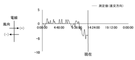
- the wind condition information providing device 100 calculates the direction along the optical fiber 4a (direction of longitudinal waves; direction of extension of the optical fiber 4a; hereinafter referred to as " The wind velocity components (respectively referred to as “parallel direction components", (referred to as the “orthogonal direction component”), and the wind conditions (wind direction, wind speed) of the span are determined based on the obtained parallel direction component and orthogonal direction component.
- FIG. 3A shows an example of time-series data of the parallel direction component (hereinafter referred to as “measured value (parallel direction)”) in a certain span, obtained by the wind condition information providing apparatus 100 as described above.
- FIG. 3B shows an example of time-series data of the orthogonal direction component (hereinafter referred to as “measured value (orthogonal direction)”) in the above span, which is obtained by the wind condition information providing apparatus 100.
- the horizontal axis of the graphs shown in FIGS. 3A and 3B is time, and the vertical axis is wind speed (m/s).
- the wind condition information providing device 100 is based on a database (for example, an equipment information database (equipment ledger database) managed by an administrator of power equipment such as an electric power company) that shows the installation status of the power transmission tower 2 and the power transmission line 3.
- a database for example, an equipment information database (equipment ledger database) managed by an administrator of power equipment such as an electric power company) that shows the installation status of the power transmission tower 2 and the power transmission line 3.
- a database for example, an equipment information database (equipment ledger database) managed by an administrator of power equipment such as an electric power company) that shows the installation status of the power transmission tower 2 and the power transmission line 3.
- a database for example, an equipment information database (equipment ledger database) managed by an administrator of power equipment such as an electric power company) that shows the installation status of the power transmission tower 2 and the power transmission line 3.
- Mutual conversion between wind conditions for each span determined as parallel and orthogonal components and wind conditions expressed in absolute direction (absolute direction with north as 0° (360°)
- the wind condition information providing device 100 transmits the current wind conditions of the span determined as described above to the power transmission line operation support device 300.
- the wind condition information providing device 100 predicts the future wind conditions of the span using the time series data of the wind conditions of the span obtained as described above, and uses the predicted wind conditions of the span to It may also be transmitted to the operation support device 300.
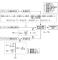
- the wind condition information providing device 100 performs the above prediction by correcting the forecast value of the wind condition obtained from the weather information obtained from the weather information providing organization. Specifically, the wind condition information providing device 100 uses the time-series data of the wind conditions in the span obtained as described above (hereinafter referred to as "first time-series data") and the time-series data obtained from the weather information.
- difference prediction formula An approximate formula (hereinafter referred to as “difference prediction formula”) expressing the difference between the forecast value of wind conditions and time series data (hereinafter referred to as “second time series data”) and the correlation between the value of the second time series data ), and by reflecting (adding) the difference obtained from the difference prediction formula to the wind condition forecast value obtained from the weather information, the future wind condition of each span is predicted.
- FIG. 4A shows an example of a graph representing a difference prediction formula for the wind direction component in the parallel direction (hereinafter referred to as “difference prediction formula (parallel direction)").
- FIG. 4B shows an example of a graph representing a differential prediction formula for wind direction components in orthogonal directions (hereinafter referred to as “difference prediction formula (orthogonal direction)").
- FIG. 6A is a diagram showing the main configuration of the wind condition information providing device 100.
- the wind condition information providing device 100 includes a processor 101, a main storage device 102 (memory), an auxiliary storage device 103 (external storage device), an input device 104, an output device 105, a communication device 106, and an optical An analysis unit 107 is provided. These are communicably connected via a bus, communication cable, or the like.
- the wind condition information providing apparatus 100 may be realized, in whole or in part, using virtual information processing resources, such as a virtual server provided by a cloud system.
- the processor 101 is, for example, a CPU (Central Processing Unit), MPU (Micro Processing Unit), GPU (Graphics Processing Unit), FPGA (Field Programmable Gate Array), ASIC (Application Specific Integrated Circuit), AI (Artificial Intelligence) chip, etc. It is configured using
- the main storage device 102 is a storage device used when the processor 101 executes a program, and includes, for example, ROM (Read Only Memory), RAM (Random Access Memory), nonvolatile memory (NVRAM (Non Volatile RAM)), etc. It is.
- the auxiliary storage device 103 is a device that stores programs and data, and includes, for example, an SSD (Solid State Drive), a hard disk drive, an optical storage device (CD (Compact Disc), DVD (Digital Versatile Disc), etc.), and a storage system. , a reading/writing device for non-temporary recording media such as an IC card, an SD card, or an optical recording medium, a non-temporary storage area of a cloud server, etc. Programs and data can be read into the auxiliary storage device 103 from a non-temporary recording medium or another information processing device equipped with a non-temporary storage device via a recording medium reading device or a communication device 106. . Programs and data stored in the auxiliary storage device 103 are read into the main storage device 102 at any time.
- an SSD Solid State Drive
- CD Compact Disc
- DVD Digital Versatile Disc
- Programs and data can be read into the auxiliary storage device 103 from a non-temporary recording medium or another information
- the input device 104 is an interface that accepts input of information from the outside, and includes, for example, a keyboard, a mouse, a touch panel, a card reader, a pen-input tablet, a voice input device, and the like.
- the output device 105 is an interface that outputs various information such as processing progress and processing results to the outside.
- the output device 105 is, for example, a display device that visualizes the above various information (liquid crystal monitor, LCD (Liquid Crystal Display), graphic card, etc.), a device that converts the above various information into audio (sound output device (speaker, etc.)) , a device (printing device, etc.) that converts the above various information into characters.
- a configuration may be adopted in which the wind condition information providing device 100 inputs and outputs information to and from another device via the communication device 106.
- the input device 104 and the output device 105 constitute a user interface that realizes interaction processing (receiving information, providing information, etc.) with the user.
- the communication device 106 is a device that realizes communication with other devices via a network 500 (LAN (Local Area Network), WAN (Wide Area Network), Internet, public communication network, dedicated line, etc.).
- the communication device 106 is a wired or wireless communication interface that realizes communication with other devices via a communication medium, and is, for example, a NIC (Network Interface Card), a wireless communication module, a USB module, etc. be.
- NIC Network Interface Card
- the optical analysis unit 107 is a device that measures the vibration state of a measurement point using DAS, and includes a vibration measurement device using C-OTDR and a signal processing circuit.
- the optical analysis unit 107 includes a CW (continuous wave) laser light source that generates a laser beam (optical pulse) input to the end face of the optical fiber 4a, an optical pulse generator, an optical amplifier, and optical equipment (optical detector, optical interference device). , including a signal processing circuit (phase calculation circuit, etc.).
- the optical analysis unit 107 and the optical fiber 4a can be connected, for example, by optically connecting the emitting part of the laser light source of the optical analysis unit 107 to the connection port (socket) of the core wire of the OPGW 4 provided in the substation 6. This is done through connection, and the connection does not cause any impact on the power system such as power outages.
- an operating system a file system, a DBMS (DataBase Management System) (relational database, NoSQL, etc.), a KVS (Key-Value Store), etc. may be installed in the wind condition information providing device 100.
- DBMS DataBase Management System
- NoSQL NoSQL
- KVS Key-Value Store
- wind condition information providing apparatus 100 can be performed by the processor 101 reading and executing programs stored in the main storage device 102, or by using the hardware (FPGA) constituting the wind condition information providing apparatus 100. , ASIC, AI chip, etc.) itself.
- the wind condition information providing device 100 stores various information (data) as, for example, a database table or a file managed by a file system.
- FIG. 6B is a block diagram illustrating the main functions of the wind condition information providing device 100.
- the wind condition information providing apparatus 100 includes a storage section 110, a vibration state measuring section 120, a span-specific wind condition acquisition section 130, a weather information acquisition section 135, a span-specific difference prediction formula generation section 140, It includes the functions of a span-by-span wind condition prediction section 145, a span-by-span current wind condition provision section 150, and a span-by-span wind condition prediction result provision section 155.
- the storage unit 110 stores vibration conditions for each measurement point 111, statistical models 112, current wind conditions for each span 113, weather information 114, difference prediction formulas for each span 115, and wind condition prediction results for each span 116.
- the vibration state measurement unit 120 measures the vibration state of each measurement point using DAS, and manages the vibration state (vibration intensity, vibration frequency) measured for each measurement point as a vibration state 111 for each measurement point.
- the span-by-span wind condition acquisition unit 130 acquires the vibration condition for each span of the power transmission line 3 (between adjacent power transmission towers 2) based on the vibration condition at each measurement point, and converts the acquired vibration condition into corresponding statistics.
- the wind conditions for each span are obtained by inputting the data to the model 112 (the above-mentioned statistical model generated for each wind speed range and each span).
- the span-by-span wind condition acquisition unit 130 manages the acquired wind condition time-series data (first time-series data) as the span-by-span current wind condition 113.
- the weather information acquisition unit 135 acquires weather information (latest information, past information) used for predicting wind conditions for each span from a weather information providing organization such as the Japan Meteorological Agency at any time via a network 500 such as the Internet. do.
- the weather information includes current wind conditions and predicted values of wind conditions in the area where the power transmission line 3 is installed.
- the weather information acquisition unit 135 manages the acquired weather information as the weather information 114. Furthermore, the weather information acquisition unit 135 mutually converts the wind conditions for each span obtained as parallel direction components and orthogonal direction components to the wind conditions expressed in absolute azimuth.
- the span-by-span difference prediction formula generation unit 140 generates the above-described difference prediction formulas (difference prediction formula (parallel direction), difference prediction formula (orthogonal direction)) for each span.
- the per-span difference prediction formula generation unit 140 manages the generated difference prediction formula for each span as the per-span difference prediction formula 115.
- the span-by-span wind condition prediction unit 145 reflects the difference obtained from the above-mentioned difference prediction formula (difference prediction formula (parallel direction), difference prediction formula (orthogonal direction)) to the wind condition forecast value obtained from the weather information. By doing so, the wind conditions for each span can be predicted.
- the span-by-span wind condition prediction unit 145 manages the predicted wind conditions for each span as a span-by-span wind condition prediction result 116.
- the per-span current wind condition providing unit 150 provides (sends) the current per-span wind condition 113 managed by the per-span wind condition acquisition unit 130 to the power transmission line operation support device 300.
- the span-by-span wind condition prediction result providing unit 155 provides (sends) the span-by-span wind condition prediction result 116 managed by the span-by-span wind condition prediction unit 145 to the power transmission line operation support device 300.
- the OPGW 4 optical fiber 4a
- the OPGW 4 optical fiber 4a
- the altitude of the power transmission line 3 can be converted and the power transmission line It may also be provided to the operation support device 300.
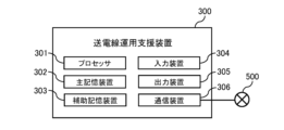
- FIG. 7A is a diagram showing the main configuration of the power transmission line operation support device 300.
- the power transmission line operation support device 300 includes a processor 301, a main storage device 302 (memory), an auxiliary storage device 303 (external storage device), an input device 304, an output device 305, and a communication device 306. . These are communicably connected via a bus, communication cable, or the like.
- the above configurations are the same as those of the processor 101, main storage device 102, auxiliary storage device 103, input device 104, output device 105, and communication device 106 of the wind condition information providing device 100, so the explanation will be omitted.
- the power transmission line operation support device 300 can be performed by the processor 301 reading and executing programs stored in the main storage device 302, or by the hardware itself configuring the power transmission line operation support device 300. Realized.
- the power transmission line operation support device 300 stores various information (data) as, for example, a database table or a file managed by a file system.
- FIG. 7B is a block diagram illustrating the main functions of the power transmission line operation support device 300.
- the power transmission line operation support device 300 includes a weather data acquisition section 310, a current value acquisition section 320, a first temperature calculation section 330A, a second temperature calculation section 330B, a temperature information output section 340, and a current capacity calculation section. 350, a current information output section 360, an allowable temperature calculation section 370, a sag acquisition section 380, and a sag information output section 390.
- the weather data acquisition unit 310 acquires predetermined types of weather data including temperature, wind conditions, and solar radiation at a predetermined position on the power transmission line 3.
- the weather data acquisition unit 310 acquires the values measured by the wind condition information providing device 100. Specifically, the meteorological data acquisition unit 310 uses the wind conditions at a predetermined position of the power transmission line 3 to calculate the wind conditions calculated based on the measurement results of the vibration state of the OPGW 4 measured using the distributed multi-point vibration measurement method. Get as. With this aspect, it is possible to obtain wind conditions measured very close to the predetermined position of the power transmission line 3, so it is possible to obtain accurate wind conditions.
- the weather data acquisition unit 310 acquires the observed values (temperature, solar radiation) at the meteorological observation point closest to the predetermined location as the values at the predetermined point.
- This weather observation may be conducted by an electric power company or by a weather information provider such as the Japan Meteorological Agency.
- the weather data acquisition unit 310 calculates the distance between each weather observation point and a predetermined position on the power transmission line 3. It is preferable to divide each value proportionally according to the above and obtain the value (temperature, solar radiation) at a predetermined position on the power transmission line 3.
- the predetermined position of the power transmission line 3 is specified in units of spans sandwiched between two adjacent power transmission towers 2, so when apportioning the values at multiple weather observation points, it is necessary to Calculation may be performed based on the distance from the observation point to any position in the span (for example, the center position of the span).
- the current value acquisition unit 320 acquires the value of the current flowing through a predetermined position of the power transmission line 3.
- the current value acquisition unit 320 acquires a current value from, for example, a current measuring device (not shown) installed in the substation 6 or the power transmission line 3 or a computer (not shown) that manages the current value of the power transmission line 3. Note that if this computer calculates a predicted value of the current value of the power transmission line 3 at a predetermined prediction target point in the future, the current value acquisition unit 320 may acquire this predicted value. Alternatively, the current value acquisition unit 320 may calculate a predicted value of the current value of the power transmission line 3.
- the first temperature calculation unit 330A calculates the temperature of the power transmission line 3 at the predetermined position based on the weather data (temperature, wind condition, solar radiation) and the current value at the predetermined position of the power transmission line 3. For example, the first temperature calculation unit 330 adds meteorological data (temperature, wind The temperature of the power transmission line 3 at a predetermined position is calculated by inputting the current value (condition, amount of solar radiation) and current value. Such an aspect makes it possible to calculate the temperature of the power transmission line 3 more accurately. Then, it becomes possible to operate the power transmission line 3 without providing excessive margin.
- Wr Joule heat due to current
- Ws Heat irradiated by sunlight
- Ww Heat dissipation due to convection
- Wra Heat dissipation due to radiation
- I Predicted power flow value (current value)
- R20 Resistance at 20°C ( ⁇ /cm)
- ⁇ Resistance temperature coefficient ( ⁇ /°C)
- ⁇ Temperature rise value of power transmission line (°C)
- T Ambient temperature (air temperature)
- E Illuminance (solar radiation amount)
- d Diameter of power transmission line (cm)
- hw Heat dissipation coefficient due to convection (W/°C ⁇ cm 2 )
- v Wind speed (m/s)
- hra Heat dissipation coefficient due to radiation ( ⁇ /°C ⁇ cm 2 )
- the first temperature calculation unit 330A inputs physical property values such as the diameter d and resistance R 20 of the power transmission line 3 along with the
- the second temperature calculation unit 330B inputs the sag at the predetermined position of the power transmission line 3 into the second relational expression representing the relationship between the temperature and the sag of the power transmission line 3. Calculate the temperature of the power transmission line 3 at .
- the sag of the power transmission line 3 at a predetermined position can be measured by measuring the sag of the power transmission line 3 using a laser, for example, and is acquired by the sag acquisition unit 380.
- the second relational expression is expressed, for example, by the following equations (8) and (9).
- the second temperature calculation unit 330B inputs physical property values such as the mass m and the diameter length L of the power transmission line 3 along with the sag Dip of the power transmission line 3 into equations (8) and (9). Calculate the current temperature T+ ⁇ . The situation is shown in FIG. 13(B).
- the second temperature calculation unit 330B may calculate the current temperature T+ ⁇ of the power transmission line 3 using equations (8), (9), and the following equation (10) as the second relational expression.
- the sag Dip can be calculated using the following equation (10).
- f0 is the natural frequency of the power transmission line 3 in the target span.
- the sag can be calculated without measuring using a laser or the like, so it is possible to safely determine the sag.
- equation (10) can be generated from equation (8) and equation (11).
- Equation (11) is an equation expressing the relationship between the tension Te of the fundamental vibrating string and the frequency f0.
- the temperature information output unit 340 outputs the temperature of the power transmission line 3 at a predetermined position on the power transmission line 3. For example, the temperature information output unit 340 displays the temperature of the power transmission line 3 as information representing the state of the power transmission line 3 on a monitor installed in a central power dispatch center or control center that manages the power system.
- the power transmission line operation support device 300 may obtain the temperature of the power transmission line 3 calculated using the first relational expression (first temperature) as the temperature of the power transmission line 3, or may calculate the temperature of the power transmission line 3 calculated using the first relational expression.
- the temperature of the power transmission line 3 is determined using either or both of the temperature of the power transmission line 3 (first temperature) and the temperature of the power transmission line 3 (second temperature) calculated using the second relational expression. Good too.
- the power transmission line operation support device 300 can adopt the higher of the first temperature and the second temperature as the temperature of the power transmission line 3. Such an aspect allows the power transmission line 3 to be operated with a higher safety factor.
- the temperature of the power transmission line 3 calculated using the second relational expression may be used as a reference value. With this aspect, it becomes possible to verify the temperature of the power transmission line 3 calculated using the first relational expression with the temperature of the power transmission line 3 calculated using the second relational expression.
- the current capacity calculation unit 350 inputs meteorological data (solar radiation, wind conditions, temperature) at a predetermined position of the power transmission line 3 and the permissible temperature (first permissible temperature) specified for the power transmission line 3 into the first relational expression. Accordingly, the current capacity at the predetermined position is calculated.
- meteorological data solar radiation, wind conditions, temperature
- the first allowable temperature is, for example, 90°C in the case of a power transmission line 3 made of ordinary aluminum (however, for a short period of time In the case of power transmission lines 3 made of heat-resistant aluminum, the temperature is 150°C (however, for short periods, up to 180°C is permissible).
- Such an aspect makes it possible to more accurately calculate the current capacity, which is the upper limit of the current value that can flow through the power transmission line 3. Then, it becomes possible to operate the power transmission line 3 without providing excessive margin.
- the current information output unit 360 outputs the difference between the current value and the current capacity at a predetermined position of the power transmission line 3.
- the temperature information output unit 340 displays the difference between the current current value and current capacity as information representing the state of the power transmission line 3 on a monitor installed at a central power dispatch center or control center that manages the power system. .
- Such an aspect makes it possible to perform supply and demand control with high precision, for example, during the summer period when electricity demand increases.
- the current information output unit 360 may individually output the current value and current capacity at a predetermined position of the power transmission line 3.
- the permissible temperature calculation unit 370 inputs the permissible value of the sag at a predetermined position of the power transmission line 3 into a second relational expression representing the relationship between the temperature and the sag of the power transmission line 3, thereby calculating the temperature of the power transmission line at the predetermined position. Calculate the allowable temperature of No. 3 (second allowable temperature).
- the allowable value of sag is determined, for example, so that the power transmission line 3 does not come into contact with surrounding trees, buildings, etc.
- the current capacity calculation unit 350 inputs the smaller value of the first allowable temperature and the second allowable temperature and the meteorological data at a predetermined position of the power transmission line 3 into the first relational expression.
- the current capacity at a predetermined position of the power transmission line 3 may be calculated.
- the allowable temperature calculation unit 370 inputs the minimum value of each allowable value of sag into the second relational expression, thereby calculating the temperature at the predetermined position. It is preferable to calculate the allowable temperature (second allowable temperature) of the power transmission line 3. With this aspect, it is possible to calculate the allowable temperature of the power transmission line 3 with higher safety.
- the sag information output unit 390 outputs the difference between the sag at a predetermined position of the power transmission line 3 and the allowable value of the sag at the predetermined position.
- the sag information output unit 390 outputs the current sag and the allowable sag as information representing the state of the power transmission line 3 to a monitor installed in a central dispatch center or control center that manages the power system. Show differences. Such an aspect makes it possible to more effectively prevent ground faults and short circuits in the power transmission line 3, which tend to occur during the high temperature period of summer, for example.
- the sag information output unit 390 may separately output the sag and the allowable value at a predetermined position of the power transmission line 3.
- the power transmission line operation support device 300 can more accurately acquire the wind conditions at a predetermined position of the power transmission line 3 and more accurately calculate the temperature of the power transmission line 3. becomes possible.
- FIG. 8 is a flowchart showing the process flow when the power transmission line operation support device 300 calculates the temperature at a predetermined position (span) of the power transmission line 3 using the first relational expression.
- the power transmission line operation support device 300 acquires weather data (S1000).
- Weather data includes temperature, solar radiation, and wind conditions.
- the power transmission line operation support device 300 also acquires the wind conditions calculated by the wind condition information providing device 100.
- the power transmission line operation support device 300 acquires the current value of the power transmission line 3 (S1010), and further acquires the physical property value of the power transmission line 3 used in the first relational expression (S1020).
- the power transmission line operation support device 300 acquires these current values and physical property values from a table (not shown) provided in the main storage device 302 or auxiliary storage device 303 or from another computer (not shown) that is communicably connected. do.
- the power transmission line operation support device 300 calculates the temperature of the power transmission line 3 by substituting each of the acquired data into the first relational expression (S1030). Then, the power transmission line operation support device 300 outputs the temperature of the power transmission line 3 (S1040).
- Such an aspect makes it possible to more accurately acquire the wind conditions at a predetermined position on the power transmission line 3 and to calculate the temperature of the power transmission line 3 more accurately.
- FIG. 9 is a flowchart showing the process flow when the power transmission line operation support device 300 calculates the difference between the current value and the current capacity of the power transmission line 3 using the first relational expression.
- the power transmission line operation support device 300 acquires weather data (S2000).
- Weather data includes temperature, solar radiation, and wind conditions. Further, as for the wind condition, a value calculated by the wind condition information providing device 100 is acquired.
- the power transmission line operation support device 300 acquires the physical property values of the power transmission line 3 used in the first relational expression (S2010), and acquires the allowable temperature of the power transmission line 3 (S2020).
- the power transmission line operation support device 300 acquires these allowable temperatures and physical property values from a table (not shown) provided in the main storage device 302 or auxiliary storage device 303 or from another computer (not shown) that is communicably connected. do.
- the power transmission line operation support device 300 calculates the current capacity of the power transmission line 3 by substituting each of the acquired data into the first relational expression (S2030). Then, the power transmission line operation support device 300 calculates and outputs the difference between the current value and the current capacity of the power transmission line 3 (S2040). Note that the current value and current capacity of the power transmission line 3 may be output separately.
- Such an aspect makes it possible to more accurately acquire the wind conditions at a predetermined position of the power transmission line 3 and to calculate the current capacity of the power transmission line 3 more accurately.
- FIG. 10 is a flowchart showing the process flow when the power transmission line operation support device 300 calculates the temperature at a predetermined position (span) of the power transmission line 3 using the second relational expression.
- the power transmission line operation support device 300 obtains the sag of the power transmission line 3 (S3000).
- the sag can be directly measured using a laser, or can be calculated using the measurement results of the natural frequency.
- the sag may be calculated by a desk calculation using the overhead wire tension data for each span stored in the power transmission line operation support device 300 and the outside temperature as parameters.
- the power transmission line operation support device 300 acquires the physical property values of the power transmission line 3 used in the second relational expression (S3010).
- the power transmission line operation support device 300 calculates the temperature of the power transmission line 3 by substituting the obtained sag and physical property values into the second relational expression (S3020). Then, the power transmission line operation support device 300 outputs the temperature of the power transmission line 3 (S3030).
- the power transmission line operation support device 300 acquires the tolerance value of sag defined for the power transmission line 3 and executes the processing up to S3030. Temperature can be output (S3000 to S3030).
- Such an aspect makes it possible to calculate the allowable temperature of the power transmission line 3 from a different perspective from the allowable temperature determined based on the amount of mechanical strength reduction of the power transmission line 3.
- the power transmission line operation support device 300 calculates a permissible temperature (second permissible temperature) calculated from the permissible value of sag and a permissible temperature (first permissible temperature) determined based on the mechanical strength reduction amount of the power transmission line 3. ) may be set as the allowable temperature, and the current capacity of the power transmission line 3 may be calculated by performing information processing according to the flowchart shown in FIG. With this aspect, it is possible to calculate a current capacity with higher safety.
- the power transmission line operation support device 300 may output the difference between the sag acquired in S3000 of FIG. 10 and a separately determined tolerance value for the sag. For example, the power transmission line operation support device 300 sends information indicating the state of the power transmission line 3 between the current sag and the allowable sag to a monitor installed at a central dispatch center or control center that manages the power system. Show differences. With this aspect, it is possible to promptly notify the operator that the sag is increasing, for example during the daytime in summer, and effectively prevent ground faults and short circuits. Of course, the power transmission line operation support device 300 may individually output the slackness and allowable value at a predetermined position of the power transmission line 3.
- the power transmission line operation support device 300 By executing the above-described processing, the power transmission line operation support device 300 according to the present embodiment more accurately acquires the wind conditions at a predetermined position on the power transmission line 3 and calculates the temperature of the power transmission line 3 more accurately. It becomes possible to do so.
- the power transmission line operation support device 300 and the control method and program for the power transmission line operation support device 300 according to the present embodiment have been described. It becomes possible to obtain the temperature of the power transmission line 3 and calculate the temperature of the power transmission line 3 more accurately.
- the predetermined position of the power transmission line 3 is a span sandwiched between two adjacent power transmission towers 2, but this predetermined position is limited to only one span (one specific span). However, there may be a plurality of spans (a plurality of spans). In the case of multiple spans, the power transmission line operation support device 300 performs the above-described information processing for each span. This makes it possible to grasp the state of the power transmission line 3, such as temperature and sag, for each span. At this time, individual values are acquired or measured for each span regarding the temperature, sag, physical property values, current value, and weather data of the power transmission line 3. As for the allowable value of the degree, it is preferable to use the minimum value among the values for each span. As a result, stricter standards are adopted, and therefore, it is possible to operate the power transmission line 3 more safely.
- the power transmission line operation support device 300 also acquires this meteorological data (for example, wind direction). and executes the information processing described above.
- meteorological data for example, wind direction
- the power transmission line operation support device 300 also acquires this meteorological data (for example, wind direction). and executes the information processing described above.
- the power transmission line operation support device 300 acquires the predicted value of the weather data at the future prediction target point and the predicted value of the current value flowing through the power transmission line 3, and predicts the temperature of the power transmission line 3 at the prediction target point. Good too. With this aspect, it becomes possible to grasp the temperature rise of the power transmission line 3 in advance and take countermeasures, so that the power transmission line 3 can be operated more safely.
- the power transmission line operation support device 300 acquires the forecast value of the weather data at the future prediction target time and the allowable temperature of the power transmission line 3, and predicts the current capacity of the power transmission line 3 at the prediction target time. good. With this aspect, it becomes possible to grasp the current capacity of the power transmission line 3 in advance and take countermeasures, so that the power transmission line 3 can be operated more safely.
- Wind condition information providing device 101
- Processor 102
- Main storage device 103
- Auxiliary storage device 104
- Input device 105
- Output device 106
- Communication device 107
- Optical analysis unit 110
- Storage section 111
- Vibration state for each measurement point 112
- Statistical model 113
- Span Current wind conditions 114
- Weather information 115
- Difference prediction formula for each span 116
- Wind condition prediction results for each span Vibration condition measurement unit
- Wind condition acquisition unit for each span 135
- Weather information acquisition unit 140
- Difference prediction formula for each span generation unit 145
- Span-by-span wind condition prediction unit 150
- Span-by-span current wind condition provision unit 155
- Span-by-span wind condition prediction result provision unit 300
- Transmission line operation support device 301
- Processor 302 Main storage device
- Auxiliary storage device 304
- Input device 305
- Output device 306
- Weather data acquisition unit 320
- Current value acquisition unit
Landscapes
- Physics & Mathematics (AREA)
- General Physics & Mathematics (AREA)
- Management, Administration, Business Operations System, And Electronic Commerce (AREA)
Priority Applications (2)
| Application Number | Priority Date | Filing Date | Title |
|---|---|---|---|
| PCT/JP2022/023360 WO2023238348A1 (ja) | 2022-06-09 | 2022-06-09 | 送電線運用支援装置、送電線運用支援装置の制御方法及びプログラム |
| JP2022554521A JPWO2023238348A1 (https=) | 2022-06-09 | 2022-06-09 |
Applications Claiming Priority (1)
| Application Number | Priority Date | Filing Date | Title |
|---|---|---|---|
| PCT/JP2022/023360 WO2023238348A1 (ja) | 2022-06-09 | 2022-06-09 | 送電線運用支援装置、送電線運用支援装置の制御方法及びプログラム |
Publications (1)
| Publication Number | Publication Date |
|---|---|
| WO2023238348A1 true WO2023238348A1 (ja) | 2023-12-14 |
Family
ID=89117801
Family Applications (1)
| Application Number | Title | Priority Date | Filing Date |
|---|---|---|---|
| PCT/JP2022/023360 Ceased WO2023238348A1 (ja) | 2022-06-09 | 2022-06-09 | 送電線運用支援装置、送電線運用支援装置の制御方法及びプログラム |
Country Status (2)
| Country | Link |
|---|---|
| JP (1) | JPWO2023238348A1 (https=) |
| WO (1) | WO2023238348A1 (https=) |
Citations (4)
| Publication number | Priority date | Publication date | Assignee | Title |
|---|---|---|---|---|
| JPS59198832A (ja) * | 1983-04-26 | 1984-11-10 | 古河電気工業株式会社 | 架空送電線の事故検出方法 |
| JP2002238147A (ja) * | 2001-02-09 | 2002-08-23 | Nissin Electric Co Ltd | 温度演算形過負荷保護リレー |
| JP2009065796A (ja) * | 2007-09-07 | 2009-03-26 | Chugoku Electric Power Co Inc:The | 架空送電線の電流容量動的決定装置、これに用いるコンピュータプログラム及び架空送電線の電流容量動的決定方法 |
| WO2021171589A1 (ja) * | 2020-02-28 | 2021-09-02 | 日本電気株式会社 | 風速特定システム、風速特定装置、及び風速特定方法 |
-
2022
- 2022-06-09 WO PCT/JP2022/023360 patent/WO2023238348A1/ja not_active Ceased
- 2022-06-09 JP JP2022554521A patent/JPWO2023238348A1/ja active Pending
Patent Citations (4)
| Publication number | Priority date | Publication date | Assignee | Title |
|---|---|---|---|---|
| JPS59198832A (ja) * | 1983-04-26 | 1984-11-10 | 古河電気工業株式会社 | 架空送電線の事故検出方法 |
| JP2002238147A (ja) * | 2001-02-09 | 2002-08-23 | Nissin Electric Co Ltd | 温度演算形過負荷保護リレー |
| JP2009065796A (ja) * | 2007-09-07 | 2009-03-26 | Chugoku Electric Power Co Inc:The | 架空送電線の電流容量動的決定装置、これに用いるコンピュータプログラム及び架空送電線の電流容量動的決定方法 |
| WO2021171589A1 (ja) * | 2020-02-28 | 2021-09-02 | 日本電気株式会社 | 風速特定システム、風速特定装置、及び風速特定方法 |
Also Published As
| Publication number | Publication date |
|---|---|
| JPWO2023238348A1 (https=) | 2023-12-14 |
Similar Documents
| Publication | Publication Date | Title |
|---|---|---|
| Tang et al. | Micro-scale wind resource assessment in complex terrain based on CFD coupled measurement from multiple masts | |
| Lee et al. | Evaluation of the wind farm parameterization in the Weather Research and Forecasting model (version 3.8. 1) with meteorological and turbine power data | |
| CN105844361B (zh) | 风电机组风功率预测方法、解缆方法和装置 | |
| Vigueras-Rodríguez et al. | Spectral coherence model for power fluctuations in a wind farm | |
| Sun et al. | Wind field reconstruction using inverse process with optimal sensor placement | |
| Li et al. | Signatures of air–wave interactions over a large lake | |
| Babanin et al. | Winds near the surface of waves: Observations and modeling | |
| Draxl et al. | Coupling mesoscale budget components to large-eddy simulations for wind-energy applications | |
| Jellen et al. | Machine-learning informed macro-meteorological models for the near-maritime environment | |
| Rivera‐Arreba et al. | Effects of atmospheric stability on the structural response of a 12 MW semisubmersible floating wind turbine | |
| Phillips et al. | Dynamic rating of overhead transmission lines over complex terrain using a large-eddy simulation paradigm | |
| Ivanova et al. | Improving wind and power predictions via four-dimensional data assimilation in the WRF model: case study of storms in February 2022 at Belgian offshore wind farms | |
| WO2023238348A1 (ja) | 送電線運用支援装置、送電線運用支援装置の制御方法及びプログラム | |
| CN110555540B (zh) | 用于评估风电场发电量的方法、装置及系统 | |
| Che et al. | An integrated wind-forecast system based on the weather research and forecasting model, Kalman filter, and data assimilation with nacelle-wind observation | |
| Natarajan et al. | Statistical extreme load extrapolation with quadratic distortions for wind turbines | |
| Wächter et al. | Power performance of wind energy converters characterized as stochastic process: applications of the Langevin power curve | |
| Naemi et al. | A hierarchical, physical and data-driven approach to wind farm modelling | |
| Han et al. | A study of the reduction of the regional aggregated wind power forecast error by spatial smoothing effects in the Maritimes Canada | |
| Ganesan et al. | Assessment of wind energy potential using topographical and meteorological data of a site in Central India (Bhopal) | |
| US20240393758A1 (en) | System and method for intelligent electronic safety response interface | |
| Guo | A simple method to downscale daily wind statistics to hourly wind data | |
| CN115263683A (zh) | 基于光纤传感的风电机组监测控制方法及系统 | |
| Barone et al. | DOE/SNL-TTU scaled wind farm technology facility | |
| Hu et al. | Use of seismic analyses for the wind energy industry |
Legal Events
| Date | Code | Title | Description |
|---|---|---|---|
| ENP | Entry into the national phase |
Ref document number: 2022554521 Country of ref document: JP Kind code of ref document: A |
|
| 121 | Ep: the epo has been informed by wipo that ep was designated in this application |
Ref document number: 22945850 Country of ref document: EP Kind code of ref document: A1 |
|
| NENP | Non-entry into the national phase |
Ref country code: DE |
|
| 122 | Ep: pct application non-entry in european phase |
Ref document number: 22945850 Country of ref document: EP Kind code of ref document: A1 |