WO2023233442A1 - Sscモードを動的に決定するための通信制御 - Google Patents
Sscモードを動的に決定するための通信制御 Download PDFInfo
- Publication number
- WO2023233442A1 WO2023233442A1 PCT/JP2022/021859 JP2022021859W WO2023233442A1 WO 2023233442 A1 WO2023233442 A1 WO 2023233442A1 JP 2022021859 W JP2022021859 W JP 2022021859W WO 2023233442 A1 WO2023233442 A1 WO 2023233442A1
- Authority
- WO
- WIPO (PCT)
- Prior art keywords
- communication
- handover
- communication status
- ssc mode
- information processing
- Prior art date
- Legal status (The legal status is an assumption and is not a legal conclusion. Google has not performed a legal analysis and makes no representation as to the accuracy of the status listed.)
- Ceased
Links
Images




Classifications
-
- H—ELECTRICITY
- H04—ELECTRIC COMMUNICATION TECHNIQUE
- H04W—WIRELESS COMMUNICATION NETWORKS
- H04W36/00—Hand-off or reselection arrangements
- H04W36/16—Performing reselection for specific purposes
- H04W36/18—Performing reselection for specific purposes for allowing seamless reselection, e.g. soft reselection
-
- H—ELECTRICITY
- H04—ELECTRIC COMMUNICATION TECHNIQUE
- H04W—WIRELESS COMMUNICATION NETWORKS
- H04W24/00—Supervisory, monitoring or testing arrangements
- H04W24/02—Arrangements for optimising operational condition
-
- H—ELECTRICITY
- H04—ELECTRIC COMMUNICATION TECHNIQUE
- H04W—WIRELESS COMMUNICATION NETWORKS
- H04W36/00—Hand-off or reselection arrangements
-
- H—ELECTRICITY
- H04—ELECTRIC COMMUNICATION TECHNIQUE
- H04W—WIRELESS COMMUNICATION NETWORKS
- H04W36/00—Hand-off or reselection arrangements
- H04W36/08—Reselecting an access point
-
- H—ELECTRICITY
- H04—ELECTRIC COMMUNICATION TECHNIQUE
- H04W—WIRELESS COMMUNICATION NETWORKS
- H04W36/00—Hand-off or reselection arrangements
- H04W36/14—Reselecting a network or an air interface
-
- H—ELECTRICITY
- H04—ELECTRIC COMMUNICATION TECHNIQUE
- H04W—WIRELESS COMMUNICATION NETWORKS
- H04W76/00—Connection management
- H04W76/30—Connection release
- H04W76/38—Connection release triggered by timers
Definitions
- the present disclosure relates to communication control technology for dynamically determining an SSC mode.
- SSC Service and Session Continuity
- 5G fifth generation mobile communication system
- 3GPP Third Generation Partnership Project
- SSC Service and Session Continuity
- SSC is a technology for mobility management when a communication terminal moves and changes the base station to which it connects, and three SSC modes have been defined so far (for example, Patent Document 1).
- SSC mode 1 is a mode that has IP address continuity, although there is a slight delay
- SSC mode 2 is a mode that has a delay (that is, there is a period of no communication) and does not have IP address continuity
- SSC mode 3 is a mode that is less likely to cause delays, but does not have continuity of IP addresses.
- a communication carrier providing a communication service takes into consideration the network configuration, etc., and sets the SSC mode to be used in advance.
- a preset SSC mode may not be an appropriate SSC mode in view of communication conditions such as the traffic environment when a communication terminal performs communication and the communication service used by the communication terminal. For example, if a communication terminal using a communication service for which real time (low delay) is not a requirement uses SSC mode 3, it may be configured to use SSC mode 1 or SSC mode 2.
- the present invention aims to provide a technique for dynamically determining an SSC mode based on communication conditions.
- an information processing device includes one or more processors, and at least one of the one or more processors executes an acquisition process, a prediction process, and a determination process.
- the acquisition process is a process of acquiring from a communication device the communication status before handover to the communication device.
- the prediction process is a process of predicting the communication status of the communication device after the handover based on the communication status before the handover using machine learning.
- the determination process is a process of determining an SSC (Service and Session Continuity) mode to be used by the communication device after handover, based on the predicted communication status after handover.
- SSC Service and Session Continuity
- a control device includes one or more processors, and at least one of the one or more processors executes an acquisition process, a determination process, and a session management process.
- the acquisition process is a process of acquiring from another device the communication status of the communication device after handover, which is predicted by machine learning based on the communication status of the communication device before handover.
- the determination process is a process of determining an SSC (Service and Session Continuity) mode to be used by the communication device after handover, based on the predicted communication status after handover.
- the session management process is a process for performing session management for the communication device to perform data communication according to the determined SSC mode.
- an information processing method includes an acquisition step of acquiring, from a communication device, a communication status before handover to the communication device, and a step of acquiring the communication status before handover to the communication device, and A prediction step of predicting the communication status after handover for the communication device by machine learning, and an SSC (Service and Session Continuity) mode used by the communication device after handover based on the predicted communication status after handover. a determining step of determining.
- FIG. 1 shows an example of a network configuration according to an embodiment of the present disclosure.
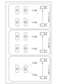
- FIG. 2 shows a diagram for explaining the SSC mode.
- FIG. 3 shows an example hardware configuration of an NWDAF node according to an embodiment of the present disclosure.
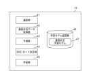
- FIG. 4 shows an example of a functional configuration of an NWDAF node according to an embodiment of the present disclosure.
- FIG. 5 shows an example of a functional configuration of an SMF node according to an embodiment of the present disclosure.
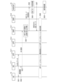
- FIG. 6 is a communication sequence diagram of SSC mode change control when the NWDAF node determines the SSC mode.
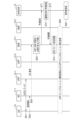
- FIG. 7 is a communication sequence diagram of SSC mode change control when the SMF node determines the SSC mode.
- FIG. 8 is a schematic diagram showing the flow of prediction processing, SSC mode determination processing, and relearning processing.
- FIG. 9 schematically shows an example of a 5G core network.
- FIG. 10 shows an example of session control when using SSC mode 3.
- a fifth generation (5G) mobile network (5G network) standardized by 3GPP (Third Generation Partnership Project) is assumed as a network to which the technology according to the present disclosure is applied. Note that the technology according to the present disclosure may be applied to networks other than 5G networks.
- FIG. 1 shows an example of a network configuration according to this embodiment.
- the network includes a user terminal (communication device, hereinafter referred to as UE) 10, base stations (also referred to as BS) 11-1, 11-2, UPF (User Plane Function) nodes 12-1, 12-2, and SMF (Session). management function) nodes 13-1 and 13-2, and an NWDAF (Network Data Analytic Function) node 14.
- Base stations 11-1 and 11-2 construct radio access networks in cells 1 and 2, respectively.
- the UPF nodes 12-1, 12-2, the SMF nodes 13-1, 13-2, and the NWDAF node 14 are nodes that function as a Network Function (NF) in the 5G core network.
- NF Network Function
- base stations 11-1 and 11-2 are base stations 11
- UPF nodes 12-1 and 12-2 are UPF nodes 12
- SMF nodes 13-1 and 13-2 are SMF nodes.
- Collectively referred to as 13 Note that the network configuration example in FIG. 1 shows a functional configuration and does not necessarily show a physical configuration.
- the UE 10 is, for example, a device such as a smartphone or a tablet, and is configured to be able to communicate wirelessly with the base station 11.
- the UE 10 has a display unit (display screen) such as a liquid crystal display, and each user can perform various operations using a GUI (Graphic User Interface) provided on the liquid crystal display.
- the operation includes various operations on content such as an image displayed on the screen, such as a tap operation, a slide operation, and a scroll operation using a finger, a stylus, or the like.
- the UE 10 may be a device such as a tablet terminal or a notebook PC.
- the user device 11 may include a separate display unit.
- FIG. 9 schematically shows an example of a 5G network.
- the 5G network 90 shown in FIG. 9 includes a UE 901, a RAN (Radio Access Network) 902, a UPF 903, an AMF (Access and Mobility Management Function) 904, an SMF 905, and a PC.
- F Policy Control Function
- NEF Network Exposure Function
- NRF Network Repository Function
- NSSF Network Slice Selection Function
- AUSF Authentication Server Function
- the UPF 903 is connected to a DN (Data Network) 913.
- DN Data Network
- the UE 10 in FIG. 1 is a device that functions as a UE 901, and the base station 11 includes at least a device that executes a RU (Radio Unit) that performs part of the functions of the RAN 902.
- the UPF node 12 is a device that functions as a UPF 903, the SMF node 13 is a device that functions as an SMF node 905, and the NWDAF node 14 is a device that functions as an NWDAF 912.
- the UPF 902 is responsible for routing and data transfer for interconnecting the DNs 913.
- the SMF 905 is responsible for session management (establishment and disconnection) of the UE 901, IP address assignment, and selection and control of the UPF 903 for data transfer.
- NWDAT 912 is responsible for data collection and analysis of the data.
- the UE 10 located in cell 1 moves from cell 1 to cell 2.
- the SSC mode to be used in the UE 10 located in the cell 1 is set in advance. Note that 3GPP defines three SSC modes, each of which will be described later with reference to FIG. 2.
- the SSC mode set in cell 1 for UE 10 can also be used in cell 2.
- the NWDAF node 14 uses machine learning to predict the communication status for the UE 10 after handover, based on the communication status for the UE 10 before handover. Furthermore, the NWDAF node 14 can determine (select) the optimal SSC mode for the UE 10 after handover based on the predicted communication situation. Alternatively, the SMF node 13-1 (control device) can determine the optimal SSC mode for the UE 10 after handover based on the predicted communication situation from the NWDAF node 14.
- FIG. 2 is a diagram for explaining the SSC mode.
- SSC mode 1 (left part of FIG. 2) is a mode in which handover is performed while maintaining the connected UPF (see the dotted line).
- SSC mode 1 is the same form as 4G (LTE (Long Term Evolution)) standardized by 3GPP.
- DN Data Network
- SSC mode 2 (center portion of FIG. 2) is a mode in which UPF and DN are switched before and after handover (see dotted line).
- the base station is switched to a UPF close to the base station to be switched to.
- SSC mode 2 a momentary interruption (timing of no communication) occurs due to reconnection of the DN session.
- SSC mode 3 (right part of FIG. 2) is a mode in which, like SSC mode 2, the UPF and DN are switched before and after handover. Unlike SSC mode 2, maintaining the UPF before switching (see the dashed line) reduces momentary interruptions due to DN session reconnection.
- FIG. 3 shows an example of the hardware configuration of the NWDAF node 14 according to this embodiment. Note that the SMF node 13 also has a similar hardware configuration.
- the NWDAF node 14 includes a CPU 31, a ROM 32, a RAM 33, an HDD 34, a communication I/F 35, and a system bus 36 as an example of a hardware configuration. NWDAF node 14 may also include external memory.
- the CPU (Central Processing Unit) 31 is composed of one or more processors, and controls the operations in the NWDAF node 14 in an integrated manner.
- the CPU 31 controls each component (32 to 35) via a system bus 36 which is a data transmission path.
- the CPU 31 includes an ASIC (Application Specific Integrated Circuit), an FPGA (Field Programmable Gate Array), a DSP (Digital Signal Processor), and a GP. It may be replaced by one or more processors such as U (Graphics Processing Unit).
- the ROM (Read Only Memory) 32 is a nonvolatile memory that stores control programs and the like necessary for the CPU 31 to execute processing.
- the program may be stored in a nonvolatile memory such as an HDD (Hard Disk Drive) 34 or an SSD (Solid State Drive), or an external memory such as a removable storage medium (not shown).
- a RAM (Random Access Memory) 33 is a volatile memory and functions as a main memory, work area, etc. of the CPU 31. That is, the CPU 31 loads necessary programs and the like from the ROM 32 into the RAM 33 when executing processing, and implements various functional operations by executing the programs and the like.
- the HDD 34 stores, for example, various data and information necessary when the CPU 31 performs processing using a program. Further, the HDD 34 stores various data, various information, etc. obtained by the CPU 31 performing processing using programs and the like. Note that the storage may be performed using an external memory such as a nonvolatile memory such as an SSD or a removable storage medium together with or in place of the HDD 204.
- the communication I/F (Interface) 35 is an interface that controls communication between the NWDAF node 14 and external devices.
- NWDAF node 14 and the SMF node 13 may be equipped with dedicated hardware for executing their respective functions, or may be equipped with hardware that executes some of their respective functions, and computers that run programs for other functions. You may execute the part. Alternatively, all functions may be performed by a computer and a program.
- FIG. 4 shows an example of the functional configuration of the NWDAF node 14 according to this embodiment.
- Each function of the NWDAF node 14 is, for example, a logical function realized by the hardware of the NWDAF node 14 shown in FIG. 3, and can be realized by the CPU 31 executing a program stored in the ROM 32 or the like.
- the NWDAF node 14 has a communication section 41, a communication status data acquisition section 42, a prediction section 43, an SSC mode determination section 44, a learning section 45, and a learning model storage section 46 as functional configurations.
- the learned model storage unit 46 stores a learned communication situation prediction model 47.
- the communication unit 41 transmits and receives various signals (related to data, packets, etc.) via the communication I/F 35.
- the communication status data acquisition unit 42 acquires communication status data (communication status data) for the UE 10 from the data received by the communication unit 41 . Communication status data will be described later.
- the prediction unit 43 applies the communication status data acquired by the communication status data acquisition unit 42 to the communication status prediction model 47 to predict the communication status after the time when the applied communication status data is acquired. (presume. In this embodiment, the communication status data acquired by the communication status data acquisition unit 42 indicates the communication status before handover, and the prediction unit 43 predicts the communication status after handover.
- the SSC mode determining unit 44 determines (selects) the optimal SSC mode after handover based on the post-handover communication situation predicted by the predicting unit 43.
- the learning unit 45 compares the communication situation predicted by the prediction unit 43 with the actual communication situation, and learns (re-learns) the communication situation prediction model 47 based on the result of the comparison.
- the learning model storage unit 46 may be configured with the RAM 33.
- the communication situation prediction model 47 stored in the learning model storage unit 46 is a learning model for machine learning, and the communication situation prediction model 47 will be described later.
- the communication status data according to this embodiment includes data regarding the UE 10. Furthermore, the communication status data according to this embodiment can include data regarding the communication environment of the UE 10.
- the data regarding the UE 10 includes the operation history (operation status) of the UE 10 by the user.
- the operation history includes, for example, the operation on the display screen (the screen is ON or OFF), the operation time of the operation on the display screen, the connection destination of the UE 10 (handover (connection base station) history), the amount of communication packets (data communication speed) , cached data, data acquired by DPI (Deep Packet Inspection), etc.
- the data regarding the UE 10 may further include movement characteristics (location information and movement speed) of the UE 10.
- the position information can be acquired by the UE 10 using a signal from a GPS (Global Positioning System) satellite (not shown), and the moving speed can be acquired based on the position information.
- GPS Global Positioning System
- the position information can also be obtained by measuring the received signal strength indicator (RSSI) of a predetermined beacon at the UE 10.
- RSSI received signal strength indicator
- Time information (indicating a time zone, a timestamp, etc.) is attached to the data regarding the UE 10. For example, in the case of the operation history, the time information indicates the time when the operation was performed, and in the case of the position information and the movement speed, the time information indicates the time when the position information and the movement speed were acquired.
- the data regarding the communication environment of the UE 10 includes the traffic environment (congestion status of the area) in the area where the UE 10 is located.
- the traffic environment can be obtained from, for example, a communication carrier.
- the data regarding the communication environment may include the type of communication area of the UE 10 (city center area or suburban area).
- the data regarding the communication environment is attached with time information, similar to the data regarding the UE 10 described above.
- FIG. 5 shows an example of the functional configuration of the SMF node 13 according to this embodiment.
- Each function of the SMF node 13 is, for example, a logical function realized by the hardware of the SMF node 13 shown in FIG. 3, and can be realized by the CPU 31 executing a program stored in the ROM 32 or the like.
- the SMF node 13 has a communication section 51, an SSC mode determination section 52, a session management section 53, and a communication status data acquisition section 54 as functional configurations.
- the communication unit 51 transmits and receives various signals (data, packets) via the communication I/F 35.
- the SSC mode determining unit 52 determines (selects) the optimal SSC mode after handover based on the communication status of the UE 10 after the handover predicted by the NWDAF node 14.
- the session management unit 53 manages sessions (establishment and disconnection) for the UE 10.
- the communication status data acquisition unit 54 acquires communication status data for the UE 10 from the data received by the communication unit 51.
- FIG. 6 is a communication sequence diagram of SSC mode change control when the NWDAF node 14 determines the SSC mode according to this embodiment.
- FIG. 6 shows an example in which the UE 10 is configured to use SSC mode 3 (or SSC mode 2) in cell 1 and SSC mode 2 (or SMF node 3) in cell 2.
- the UE 10 performs data communication with a DN (not shown) via the base station 11-1 and the UPF 12-1 using UL (Uplink) and DL (Downlink).
- the UE 10 measures the reception quality of cell 1 (serving cell) and cell 2 (adjacent cell), generates a measurement report (MR), and transmits the measurement report to the base station 11-1 (S62).
- the base station 11-1 determines to start handover (HO) based on the measurement report, and transmits a handover request to the SMF node 13-1 (S63).
- the communication unit 51 of the SMF node 13-1 receives the handover request, and the session management unit 53 determines that it is necessary to change the UPF/SMF (S64). Note that in FIG. 6, the SMF node 13-1 determines that it is necessary to change the UPF/SMF due to the measurement report (S62) and handover request (S63), but due to other triggers, the SMF node 13-1 determines that the UPF/SMF change is necessary. You may make a judgment.
- the SSC mode determination unit 52 of the SMF node 13-1 transmits an SSC mode determination request to the NWDAF node 14 via the communication unit 51 (S65).
- the NWDAF node 14 receives the SSC mode determination request through the communication unit 41 and performs SSC mode determination processing (S66).
- SSC mode determination process in S66 will be explained with reference to FIG.
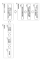
- FIG. 8 is a schematic diagram showing the flow of prediction processing, SSC mode determination processing, and relearning processing according to this embodiment. In S66, prediction processing 80 and SSC mode determination processing 81 shown in FIG. 8 are performed.
- the communication status data acquisition unit 42 of the NWDAF node 14 acquires communication status data for the UE 10 in the cell 1 (communication status 801 before handover) via the communication unit 41.
- the communication status data includes data regarding the UE 10 and can further include data regarding the communication environment of the UE 10.
- the prediction unit 43 applies the communication situation 801 to the communication situation prediction model 47 to predict the communication situation 802 after handover.
- the communication status prediction model 47 is a learning model for machine learning that is trained using arbitrary communication status data (learning data) before and after handover.
- the communication status prediction model 47 is configured to input the communication status (communication status data) before the handover and output (estimate) the communication status (communication status data) after the handover.
- the prediction unit 43 may optionally It is possible to predict which users will be operating the display screen after handover. That is, the prediction unit 43 applies the operation status on the display screen to the communication status prediction model 47 as the pre-handover communication status (input) of the arbitrary user, and calculates the post-handover operation status of the arbitrary user, that is, It is possible to predict whether the user is operating the display screen after handover.
- the SSC mode determination unit 44 of the NWDAF node 14 determines the SSC mode according to a predetermined rule based on the predicted communication situation 802.
- the SSC mode may also be determined using the communication status 801 before handover.
- the predetermined rule is a rule in which an SSC mode is assigned in advance to a communication situation. An example of the rule will be shown for the UE 10.
- SSC mode 2 When it is predicted that no operation is being performed on the UE 10 after handover (for example, the display screen of the UE 10 is turned off): SSC mode 2 (2) After the handover, the operation of the UE 10 is being performed, but it is predicted that the operation will be completed in a relatively short time (for example, the amount of communication packets until the operation is completed is less than a predetermined threshold), or When the moving speed of the UE 10 is slower than the predetermined speed (for example, walking level), there is time to spare until the next handover: SSC mode 1 (3) After handover, when the UE 10 is being operated and it is predicted that the operation will continue for a relatively long time (for example, the amount of communication packets until the end of the operation is greater than or equal to a predetermined threshold): SSC mode 3
- an appropriate SSC mode is selected according to the predicted communication situation.
- rules (1) to (3) described above are just examples, and rules classified based on time information, movement characteristics, or communication environment that may be included in communication status data may be used. Further, the rules are set in advance based on the characteristics of the SSC mode and empirical rules, but may be changed depending on predetermined conditions.
- the SSC mode determining unit 44 of the NWDAF node 14 notifies the SSC mode determined in S66 to the SMF node 13-1 via the communication unit 41. Thereafter, the SMF node 13-1 performs session release processing with the UPF node 12-1 and session establishment processing with the UPF node 12-2 with the UE 10 (S68).
- session release processing is performed after session establishment processing
- session establishment processing is performed after session release processing. I can.
- the learning unit 45 of the NWDAF node 14 re-learns the communication situation prediction model 47 (S69).
- S69 relearning processing 82 shown in FIG. 8 is performed.
- the communication status data acquisition unit 42 acquires actual communication status data (actual communication status) after handover.
- the learning unit 45 compares the predicted communication status 802 and the actual communication status (S822), and learns (re-learns) the communication status prediction model 47 based on the comparison result.
- the communication status data acquisition unit 42 determines whether the UE 10 is being operated as the actual communication status (communication status data) of the UE 10 after handover. Suppose that it is obtained that there is no such thing (that is, SSC mode 2 is actually appropriate). Further, it is assumed that the communication status of the UE 10 predicted by the prediction unit 43 is that the UE 10 is being operated, but the operation will be completed in a relatively short time (that is, SSC mode 1 is set based on the prediction). (should have been selected).
- the learning unit 45 compares the actual communication situation with the predicted communication situation, determines that the two are different, and inputs the correct information (in this case, that the UE 10 is not operated).
- the communication status prediction model 47 is trained (re-learned) so as to correspond to the data (communication status before handover). Through such relearning, it is expected that the prediction accuracy of the communication situation prediction model 47 will increase.
- FIG. 7 is a communication sequence diagram of SSC mode change control when the SMF node 13-1 determines the SSC mode according to this embodiment. Similar to FIG. 6, FIG. 7 shows an example where the UE 10 is configured to use SSC mode 3 (or SSC mode 2) in cell 1 and SSC mode 2 (or SMF node 3) in cell 2. show. Moreover, the same reference numerals are given to the same processes as in FIG. 6, and the description thereof will be omitted.
- the SSC mode determination unit 52 transmits a communication status prediction request to the NWDAF node 14 via the communication unit 501.
- the communication status data acquisition unit 54 may acquire communication status data from the UE 10 and transmit it to the NWDAF node 14.
- the prediction unit 43 of the NWDAF node 14 receives the prediction request via the communication unit 41, it predicts the communication status after handover according to the prediction process 80 shown in FIG. 8 (S72).
- the prediction unit 43 of the NWDAF node 14 transmits the predicted communication status 802 to the SMF node 13-1 via the communication unit 41 as a prediction result (S73).
- the SSC mode determining unit 52 of the SMF node 13-1 determines the SSC mode.
- the SSC mode determination process is similar to the SSC mode determination process 81 described above.
- the processes in S68 and S69 after determining the SSC mode are as described above.
- SSC mode determination process 80 and SSC mode determination processing 81 can be applied to any case of changing the SSC mode.
- the communication situation for the UE 10 can be predicted, and an SSC mode suitable for after the handover can be determined according to the predicted communication situation.
- the communication status is predicted by a learning model for machine learning, and the learning model continues to be retrained based on the actual communication status, making it possible to predict the communication status with high accuracy. .
- the communication status is predicted and the SSC mode is determined for the UE 10 to be handed over, but if the communication status for the UE 10 changes, this embodiment is applicable without being limited to handover. You may. For example, when the wireless connection between the UE 10 and the base station 11 is once broken and the UE 10 reconnects, the SSC mode used by the UE 10 after the reconnection is determined based on the communication status before the reconnection. It's okay.
- ⁇ Modification 1> the process of determining the SSC mode after handover for the UE 10 has been described.
- the number of UEs connected to a communication network is enormous, and performing the above-described SSC mode determination process for all UEs requires a high processing load. Therefore, for example, among a plurality of moving UEs, UEs that satisfy a predetermined condition may be selected (narrowed down) as UEs to be subjected to the SSC mode determination process.
- the narrowing down may be performed by the SMF node or the NWDAF node (in the network shown in FIG. 1, the SMF node 13-1 or the NWDAF node 14), or by another device (including the UE itself). .
- selection processing is performed by the NWDAF node 14 will be described.
- one or more UEs that are operating a predetermined application may be subjected to the SSC mode determination process. That is, the process of determining the SSC mode may be applied to one or more UEs for which the predetermined application operation has been acquired by the communication status data acquisition unit 42 as the communication status before handover. In this case, one or more UEs for which a predetermined application operation has not been obtained may be controlled to use SSC mode 2, which can cause momentary interruptions, as a default.
- the handover history of the UE may be used. For example, by analyzing the past handover history acquired by the communication status data acquisition unit 42, handover is performed from the first base station to the second base station at the first time timing, and from the second base station to the third base station at the second time timing. Assume that a predetermined number or more of UEs to be handed over to a base station are detected. In this case, it is assumed that these UEs were moving by the same moving object (having the same movement characteristics), such as a bus, a train.
- the plurality of UEs may be considered to be moving, and processing for determining the SSC mode may be applied to the UEs. In this case, it becomes possible to estimate the movement of the UE without acquiring the movement characteristics of the UE.
- a predetermined time range from the first time timing and a predetermined time range from the second time timing are considered to be the same timing as the first time timing and the second time timing, respectively.
- processing for determining the SSC mode may be applied to one or more UEs connected to a base station forming a cell in which the number of UEs to be handed over within a certain period of time is greater than a predetermined number. It's okay.
- SSC mode 3 is determined as the optimal SSC mode after handover, the session that was established first of the two sessions that will be temporarily established based on the predicted communication status after handover Control may be performed to make the opening timing earlier than a preset timing.
- This control can be performed by an SMF node or an NWDAF node (in the network shown in FIG. 1, the SMF node 13-1 or the NWDAF node 14).
- NWDAF node in the network shown in FIG. 1, the SMF node 13-1 or the NWDAF node 14.
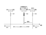
- FIG. 10 shows an example of session control when using SSC mode 3.
- SSC mode 3 when SSC mode 3 is selected, the period from the establishment timing 101 of a new session (new session) to the original release timing 103 of the previously established session (old session) is set in advance. It is assumed that In FIG. 10, before handover, the session management unit 53 maintains the old session.
- SSC mode 3 is determined as the optimal SSC mode after handover, based on the communication status data of the UE acquired by the communication status data acquisition unit 54, the session management unit 53 determines the old session release timing. may be advanced from the original old session release timing 103.
- the session management unit 53 changes the old session release timing from the time when the operation of the UE 10 is predicted to end to the original old session release timing 103.
- the session may be released at timing 102 before release timing 103. This enables effective use of network resources.
- the SSC mode determining unit 44 transmits the old session release timing changed based on the communication status data acquired by the communication status data acquisition unit 42 via the communication unit 41. It may also be notified to the SMF node 13-1. Upon receiving the notification, the session management unit 42 of the SMF node 13-1 can change the old session release timing to timing 102 and release the session.
- An acquisition process comprising one or more processors, in which at least one of the one or more processors acquires a communication status before handover from a communication device to the communication device, and based on the communication status before handover. , a prediction process that uses machine learning to predict the communication status of the communication device after handover; ) A determination process for determining a mode is executed.
- the prediction process calculates the communication status after the handover using the learning model for machine learning configured to input the communication status before the handover and output the communication status after the handover.
- the information processing device according to [1] or [2], which includes making a prediction.
- the acquisition process further includes acquiring, from the communication device, a post-handover communication status for the communication device, and further includes obtaining information predicted in the prediction process by at least one of the one or more processors.
- a learning process for learning the learning model is executed using a comparison result between the post-handover communication status acquired by the acquisition process and the post-handover communication status acquired by the acquisition process.
- the information processing device according to any one of.
- the determination process may include determining, as the SSC mode, an SSC mode corresponding to the predicted post-handover communication situation according to a predetermined rule.
- At least one of the one or more processors further executes a selection process of selecting one or more communication devices that satisfy a predetermined condition from the plurality of communication devices, and the selected one or more communication devices.
- At least one of the one or more processors further temporarily establishes SSC mode 2 based on the predicted post-handover communication status.
- [12] Comprising one or more processors, and predicted by at least one of the one or more processors by machine learning based on the communication status before the handover to the communication device from another device, after handover to the communication device.
- a determination process that determines an SSC (Service and Session Continuity) mode to be used by the communication device after handover based on the predicted communication status after handover;
- a control device that executes a session management process for performing session management for the communication device to perform data communication according to the selected SSC mode.
- SSC Service and Session Continuity
- the session management process selects the first of the two temporarily established sessions based on the predicted post-handover communication status.
- the control device according to [12] or [13], the control device including performing control to advance the timing of opening a session that has been established in advance from a timing that has been set in advance.
- control device according to any one of [10] to [14], wherein the control device is a device that functions as an SMF (Session Management Function).
- SMF Session Management Function
- SSC Service and Session Continuity
- a computer-implemented control method comprising: a session management step for performing;
- a computer-readable storage medium that stores a program, the program, when executed by one or more processors of an information processing device, allows the information processing device to perform handover from a communication device to the communication device.
- an acquisition process that acquires the previous communication status; a prediction process that uses machine learning to predict the communication status after the handover for the communication device based on the communication status before the handover; and the predicted communication status after the handover.
- SSC Service and Session Continuity
- a computer-readable storage medium that stores a program, wherein the program, when executed by one or more processors of a control device, allows the control device to receive information before handover from another device to a communication device.
- a memory including an instruction for executing a determination process for determining an SSC (Service and Session Continuity) mode, and a session management process for performing session management for the communication device to perform data communication according to the determined SSC mode.
- SSC Service and Session Continuity
Landscapes
- Engineering & Computer Science (AREA)
- Computer Networks & Wireless Communication (AREA)
- Signal Processing (AREA)
- Mobile Radio Communication Systems (AREA)
Abstract
Description
図1は、本実施形態によるネットワーク構成例を示す。当該ネットワークは、ユーザ端末(通信装置、以下UEと称す)10、基地局(BSとも記載)11-1、11-2、UPF(User Plane Function)ノード12-1、12-2、SMF(Session Management Function)ノード13-1、13-2、およびNWDAF(Network Data Analytic Function)ノード14から構成される。基地局11-1と11-2はそれぞれ、形成するセル1、2において無線アクセスネットワークを構築している。UPFノード12-1、12-2、SMFノード13-1、13-2、およびNWDAFノード14は、5GコアネットワークにおいてNetwork Function(NF)として機能するノードである。以下の説明において、特に指定しない限り、基地局11-1、11-2を基地局11、UPFノード12-1、12-2をUPFノード12、SMFノード13-1、13-2をSMFノード13と総称する。なお、図1のネットワーク構成例は、機能構成を示すものであり、必ずしも物理的な構成を示すものではない。
まず、図2を参照して、3GPPで規定されている3つのSSCモードについて説明する。図2は、SSCモードを説明するための図である。
SSCモード1(図2の左部分)は、繋がっているUPFを維持してハンドオーバするモードである(点線を参照)。SSCモード1は、3GPPで規格化された4G(LTE(Long Term Evolution))と同じ形態である。SSCモード1の場合、DN(Data Network)セッションやUE10が使用するIPアドレスは維持される一方、遅延が生じうる。
SSCモード2(図2の中央部分)は、ハンドオーバ前後でUPFとDNを切り替えるモードである(点線を参照)。例えば、切り替える基地局に近いUPFに切り替えられる。SSCモード2の場合、DNセッションの再接続による瞬断(無通信タイミング)が発生する。また、SSCモード2の場合、ハンドオーバ前後でUE10のIPアドレスを変える(IP-AからIP-B)必要があるため、IPアドレスを2つ用意する必要がある。
SSCモード3(図2の右部分)は、SSCモード2と同様に、ハンドオーバ前後でUPFとDNを切り替えるモードである。SSCモード2と異なり、切り替え前のUPFを維持することで(一点鎖線を参照)、DNセッション再接続による瞬断が軽減される。新しいエリアにおけるDNとの接続が完了後に、旧エリアにおけるDNとの通信が切断される。SSCモード3の場合、一時的に、セッションやUPFといったネットワークリソースを二重に保持した状態となる。また、SSCモード3の場合、SSCモード2の場合と同様に、ハンドオーバ前後でUE10のIPアドレスを変える(IP-AからIP-B)必要があるため、IPアドレスを2つ用意する必要がある。
図3に、本実施形態によるNWDAFノード14のハードウェア構成例を示す。なお、SMFノード13も、同様のハードウェア構成を有する。
CPU(Central Processing Unit)31は、1つ以上のプロセッサにより構成され、NWDAFノード14における動作を統括的に制御するものである。CPU31は、データ伝送路であるシステムバス36を介して、各構成部(32から35)を制御する。CPU31は、ASIC(Application specific integrated circuit)、FPGA(Field Programmable Gate Array)、DSP(Digital Signal Processor)、GPU(Graphics Processing Unit)等の1つ以上のプロセッサによって置き換えられてもよい。
RAM(Random Access Memory)33は、揮発性メモリであり、CPU31の主メモリ、ワークエリア等として機能する。すなわち、CPU31は、処理の実行に際してROM32から必要なプログラム等をRAM33にロードし、当該プログラム等を実行することで各種の機能動作を実現する。
通信I/F(Interface)35は、NWDAFノード14と外部装置との通信を制御するインタフェースである。
図4に、本実施形態によるNWDAFノード14の機能構成例を示す。NWDAFノード14の各機能は、例えば、図3に示すNWDAFノード14のハードウェアによって実現される論理的な機能であり、CPU31がROM32等に格納されたプログラムを実行することによって実現されうる。本実施形態では、NWDAFノード14は、機能構成として、通信部41、通信状況データ取得部42、予測部43、SSCモード決定部44、学習部45、および学習モデル記憶部46を有する。学習モデル記憶部46には、学習済みの通信状況予測モデル47が格納されている。
当該UE10に関するデータには、時間情報(時間帯やタイムスタンプ等を示す)が付されている。例えば、当該時間情報は、当該操作履歴の場合は、当該操作が行われた時間を示し、当該位置情報と当該移動速度の場合は、当該位置情報と当該移動速度が取得された時間を示す。
図5に、本実施形態によるSMFノード13の機能構成例を示す。SMFノード13の各機能は、例えば、図3に示すSMFノード13のハードウェアによって実現される論理的な機能であり、CPU31がROM32等に格納されたプログラムを実行することによって実現されうる。本実施形態では、SMFノード13は、機能構成として、通信部51、SSCモード決定部52、セッション管理部53、および通信状況データ取得部54を有する。
図6を参照して、NWDAFノード14がSSCモードを決定する場合の処理の流れについて説明する。図6は、本実施形態によるNWDAFノード14がSSCモードを決定する場合のSSCモード変更制御の通信シーケンス図である。図6は、UE10がセル1ではSSCモード3(またはSSCモード2)を使用し、セル2ではSSCモード2(またはSMFノード3)を使用するように構成される例を示す。
(1)ハンドオーバ後において、UE10の操作が行われていない(例えば、UE10の表示画面がOFFになっている)と予測される場合:SSCモード2
(2)ハンドオーバ後において、UE10の操作が行われているが、比較的短い時間で操作を終了する(例えば、操作終了までの通信パケット量が所定閾値よりも少ない)と予測される、または、UE10の移動速度が所定速度より遅く(例えば、徒歩レベル)次回のハンドオーバまでの時間的余裕がある場合:SSCモード1
(3)ハンドオーバ後において、UE10の操作が行われており、比較的長い時間操作が継続される(例えば、操作終了までの通信パケット量が所定閾値以上)と予測される場合:SSCモード3
次に、図7を参照して、SMFノード13-1がSSCモードを決定する場合の処理の流れについて説明する。図7は、本実施形態によるSMFノード13-1がSSCモードを決定する場合のSSCモード変更制御の通信シーケンス図である。図6と同様に、図7は、UE10がセル1ではSSCモード3(またはSSCモード2)を使用し、セル2ではSSCモード2(またはSMFノード3)を使用するように構成される例を示す。また、図6と同様の処理については、同じ参照符号を付し、説明を省略する。
上記実施形態では、UE10に対して、ハンドオーバ後のSSCモードを決定する処理について説明した。一方で、実際には、通信ネットワークに接続されているUEの数は膨大であり、全てのUEに対して、前述のSSCモード決定処理を行うことは処理負荷が高い。そこで、例えば、移動している複数のUEのうち、所定の条件を満たすUEを、SSCモード決定処理の対象とするUEとして選択しても(絞り込んでも)よい。当該絞り込みは、SMFノードやNWDAFノード(図1に示すネットワークでは、SMFノード13-1またはNWDAFノード14)により行われてもよいし、別の装置(UE自身を含む)によって行われてもよい。ここでは、NWDAFノード14によって選択処理を行う例を説明する。
ハンドオーバ後の最適なSSCモードとして、SSCモード3が決定された場合、予測されたハンドオーバ後の通信状況に基づいて、一時的に確立される2つのセッションのうちの、先に確立されていたセッションの開放タイミングを、予め設定されていたタイミングより早める制御が行われてもよい。当該制御は、SMFノードやNWDAFノード(図1に示すネットワークでは、SMFノード13-1またはNWDAFノード14)により行われうる。ここでは、SMFノード13-1によって当該制御を行う例を説明する。
本開示は以下の実施形態を含む。
[1]1以上のプロセッサを備え、前記1以上のプロセッサの少なくとも一つによって、通信装置から、前記通信装置に対するハンドオーバ前の通信状況を取得する取得処理と、前記ハンドオーバ前の通信状況に基づいて、前記通信装置に対するハンドオーバ後の通信状況を、機械学習により予測する予測処理と、 前記予測されたハンドオーバ後の通信状況に基づいて、ハンドオーバ後の前記通信装置により使用されるSSC(Service and Session Continuity)モードを決定する決定処理と、が実行される、情報処理装置。
Claims (16)
- 1以上のプロセッサを備え、
前記1以上のプロセッサの少なくとも一つによって、
通信装置から、前記通信装置に対するハンドオーバ前の通信状況を取得する取得処理と、
前記ハンドオーバ前の通信状況に基づいて、前記通信装置に対するハンドオーバ後の通信状況を、機械学習により予測する予測処理と、
前記予測されたハンドオーバ後の通信状況に基づいて、ハンドオーバ後の前記通信装置により使用されるSSC(Service and Session Continuity)モードを決定する決定処理と、
が実行される、情報処理装置。 - 前記通信状況は、ユーザによる前記通信装置に対する操作状況を含む、
請求項1に記載の情報処理装置。 - 前記予測処理は、前記ハンドオーバ前の通信状況を入力として前記ハンドオーバ後の通信状況を出力するように構成された前記機械学習のための学習モデルを用いて、前記ハンドオーバ後の通信状況を予測することを含む、
請求項1に記載の情報処理装置。 - 前記取得処理は、さらに、前記通信装置から、前記通信装置に対するハンドオーバ後の通信状況を取得することを含み、
前記1以上のプロセッサの少なくとも一つによって、さらに、
前記予測処理において予測された前記ハンドオーバ後の通信状況と、前記取得処理により取得された前記ハンドオーバ後の通信状況との比較の結果を用いて、前記学習モデルを学習させる学習処理、
が実行される、請求項1に記載の情報処理装置。 - 前記決定処理は、所定のルールにおいて、前記予測されたハンドオーバ後の通信状況に対応するSSCモードを、前記SSCモードとして決定することを含む、
請求項1に記載の情報処理装置。 - 前記1以上のプロセッサの少なくとも一つによって、さらに、
複数の通信装置から、所定の条件を満たす1以上の通信装置を選択する選択処理が実行され、
前記選択された1以上の通信装置のそれぞれに対して、前記予測処理と前記決定処理が実行される、
請求項1に記載の情報処理装置。 - 前記所定の条件は、ハンドオーバ前の前記通信状況が、所定のアプリケーションの操作を含むことである、
請求項6に記載の情報処理装置。 - 前記所定の条件は、同じ移動特徴を有することである、
請求項6に記載の情報処理装置。 - 前記所定の条件は、一定時間内にハンドオーバする通信装置の数が所定数より多いセルを形成する基地局に接続されていることである、
請求項6に記載の情報処理装置。 - 前記決定されたSSCモードがSSCモード3である場合、
前記1以上のプロセッサの少なくとも一つによって、さらに、前記予測されたハンドオーバ後の通信状況に基づいて、一時的に確立される2つのセッションのうちの、先に確立されていたセッションの開放タイミングを、予め設定されていたタイミングより早める制御を行う制御処理が実行される、
請求項1に記載の情報処理装置。 - 前記情報処理装置は、NWDAF(Network Data Analytic Function)として機能する装置である、
請求項1に記載の情報処理装置。 - 1以上のプロセッサを備え、
前記1以上のプロセッサの少なくとも一つによって、
他の装置から、通信装置に対するハンドオーバ前の通信状況に基づいて機械学習により予測された、前記通信装置に対するハンドオーバ後の通信状況を取得する取得処理と、
前記予測されたハンドオーバ後の通信状況に基づいて、ハンドオーバ後の前記通信装置により使用されるSSC(Service and Session Continuity)モードを決定する決定処理と、
前記決定されたSSCモードに従って、前記通信装置がデータ通信を行うためのセッション管理を行うセッション管理処理と、
が実行される、制御装置。 - 前記通信状況は、ユーザによる前記通信装置に対する操作状況を含む、
請求項12に記載の制御装置。 - 前記決定されたSSCモードがSSCモード3である場合、
前記セッション管理処理は、前記予測されたハンドオーバ後の通信状況に基づいて、一時的に確立される2つのセッションのうちの、先に確立されていたセッションの開放タイミングを、予め設定されていたタイミングより早める制御を行うことを含む、
請求項12に記載の制御装置。 - 制御装置は、SMF(Session Management Function)として機能する装置である、
請求項12に記載の制御装置。 - 通信装置から、前記通信装置に対するハンドオーバ前の通信状況を取得する取得工程と、
前記ハンドオーバ前の通信状況に基づいて、前記通信装置に対するハンドオーバ後の通信状況を、機械学習により予測する予測工程と、
前記予測されたハンドオーバ後の通信状況に基づいて、ハンドオーバ後の前記通信装置により使用されるSSC(Service and Session Continuity)モードを決定する決定工程と、
を含む、コンピュータによって実行される情報処理方法。
Priority Applications (2)
| Application Number | Priority Date | Filing Date | Title |
|---|---|---|---|
| US17/796,776 US12356267B2 (en) | 2022-05-30 | 2022-05-30 | Communication control for dynamically determining SSC mode |
| PCT/JP2022/021859 WO2023233442A1 (ja) | 2022-05-30 | 2022-05-30 | Sscモードを動的に決定するための通信制御 |
Applications Claiming Priority (1)
| Application Number | Priority Date | Filing Date | Title |
|---|---|---|---|
| PCT/JP2022/021859 WO2023233442A1 (ja) | 2022-05-30 | 2022-05-30 | Sscモードを動的に決定するための通信制御 |
Publications (1)
| Publication Number | Publication Date |
|---|---|
| WO2023233442A1 true WO2023233442A1 (ja) | 2023-12-07 |
Family
ID=89025864
Family Applications (1)
| Application Number | Title | Priority Date | Filing Date |
|---|---|---|---|
| PCT/JP2022/021859 Ceased WO2023233442A1 (ja) | 2022-05-30 | 2022-05-30 | Sscモードを動的に決定するための通信制御 |
Country Status (2)
| Country | Link |
|---|---|
| US (1) | US12356267B2 (ja) |
| WO (1) | WO2023233442A1 (ja) |
Citations (4)
| Publication number | Priority date | Publication date | Assignee | Title |
|---|---|---|---|---|
| JP2019096952A (ja) * | 2017-11-20 | 2019-06-20 | シャープ株式会社 | ユーザ装置 |
| JP2021087082A (ja) * | 2019-11-27 | 2021-06-03 | 株式会社京三製作所 | 学習モデル生成方法、推定装置および無線列車制御システム |
| JP2021184523A (ja) * | 2020-05-21 | 2021-12-02 | シャープ株式会社 | UE(User Equipment) |
| JP2022010968A (ja) * | 2020-06-29 | 2022-01-17 | Necプラットフォームズ株式会社 | 学習装置、通信システム、学習方法及び学習プログラム |
Family Cites Families (5)
| Publication number | Priority date | Publication date | Assignee | Title |
|---|---|---|---|---|
| GB2552845A (en) | 2016-08-12 | 2018-02-14 | Nec Corp | Communication system |
| WO2020254859A1 (en) * | 2019-06-19 | 2020-12-24 | Telefonaktiebolaget Lm Ericsson (Publ) | Machine learning for handover |
| US11792707B2 (en) * | 2021-03-19 | 2023-10-17 | Dish Wireless L.L.C. | Intelligent mobility in communication networks |
| CN116530199B (zh) * | 2021-04-06 | 2026-01-09 | Lg电子株式会社 | Pdu会话管理方法 |
| US20240276564A1 (en) * | 2021-08-03 | 2024-08-15 | Samsung Electronics Co., Ltd. | A method and equipment for session setup |
-
2022
- 2022-05-30 WO PCT/JP2022/021859 patent/WO2023233442A1/ja not_active Ceased
- 2022-05-30 US US17/796,776 patent/US12356267B2/en active Active
Patent Citations (4)
| Publication number | Priority date | Publication date | Assignee | Title |
|---|---|---|---|---|
| JP2019096952A (ja) * | 2017-11-20 | 2019-06-20 | シャープ株式会社 | ユーザ装置 |
| JP2021087082A (ja) * | 2019-11-27 | 2021-06-03 | 株式会社京三製作所 | 学習モデル生成方法、推定装置および無線列車制御システム |
| JP2021184523A (ja) * | 2020-05-21 | 2021-12-02 | シャープ株式会社 | UE(User Equipment) |
| JP2022010968A (ja) * | 2020-06-29 | 2022-01-17 | Necプラットフォームズ株式会社 | 学習装置、通信システム、学習方法及び学習プログラム |
Also Published As
| Publication number | Publication date |
|---|---|
| US12356267B2 (en) | 2025-07-08 |
| US20240187947A1 (en) | 2024-06-06 |
Similar Documents
| Publication | Publication Date | Title |
|---|---|---|
| CN111083750B (zh) | 一种移动切换方法及相关设备 | |
| EP3596969B1 (en) | Slice-compliant handover control | |
| US10080153B2 (en) | Device and method for modifying cell measurements based on device mobility | |
| US10063385B2 (en) | Method and device for processing interruption of group communication service | |
| Tartarini et al. | Software-defined handover decision engine for heterogeneous cloud radio access networks | |
| CN112333780A (zh) | 用于网络切片重选的系统和方法 | |
| WO2017024591A1 (zh) | 一种接入网设备、用户设备、通信系统及通信方法 | |
| CN106604330B (zh) | 异构网络中SeNB 的切换方法、通信系统以及MeNB | |
| US9374735B2 (en) | Method and apparatus for data flow management | |
| CN116456413A (zh) | 一种切换方法、装置、终端及计算机可读存储介质 | |
| CN111093236A (zh) | 一种信息发送、接收方法、装置、设备和存储介质 | |
| Marwat et al. | Congestion‐aware handover in LTE Systems for Load Balancing in transport network | |
| US9414283B2 (en) | Method and apparatus for controlling transfer of network traffic | |
| WO2021026674A1 (en) | Handover in integrated networks | |
| US11503452B2 (en) | Systems and methods providing a station with a suggestion to transition from Wi-Fi to LTE | |
| CN117279048A (zh) | 小区切换方法及装置、计算机可读存储介质 | |
| WO2023233442A1 (ja) | Sscモードを動的に決定するための通信制御 | |
| WO2024256075A1 (en) | Training of a machine learning model based on ue measurements made before and after a change of primary radio access node | |
| JP2010288029A (ja) | 通信システム、移動管理装置、通信方法、及び通信プログラム | |
| WO2024127471A1 (ja) | 制御装置、無線通信システム、制御方法、及びプログラム | |
| JP2025115683A (ja) | 移動通信ネットワークのネットワークノード及びコンピュータプログラム | |
| WO2024256143A1 (en) | Operations at radio access nodes | |
| WO2024256081A1 (en) | Operations at radio access nodes | |
| CN120730287A (zh) | 无线通信系统中的节点、用户设备及其执行的方法 | |
| CN121693953A (zh) | 用于网络负载平衡的体验质量感知方法 |
Legal Events
| Date | Code | Title | Description |
|---|---|---|---|
| WWE | Wipo information: entry into national phase |
Ref document number: 17796776 Country of ref document: US |
|
| 121 | Ep: the epo has been informed by wipo that ep was designated in this application |
Ref document number: 22944732 Country of ref document: EP Kind code of ref document: A1 |
|
| NENP | Non-entry into the national phase |
Ref country code: DE |
|
| 122 | Ep: pct application non-entry in european phase |
Ref document number: 22944732 Country of ref document: EP Kind code of ref document: A1 |
|
| NENP | Non-entry into the national phase |
Ref country code: JP |
|
| WWG | Wipo information: grant in national office |
Ref document number: 17796776 Country of ref document: US |