WO2023219083A1 - 液体水素移送システム - Google Patents
液体水素移送システム Download PDFInfo
- Publication number
- WO2023219083A1 WO2023219083A1 PCT/JP2023/017457 JP2023017457W WO2023219083A1 WO 2023219083 A1 WO2023219083 A1 WO 2023219083A1 JP 2023017457 W JP2023017457 W JP 2023017457W WO 2023219083 A1 WO2023219083 A1 WO 2023219083A1
- Authority
- WO
- WIPO (PCT)
- Prior art keywords
- liquid hydrogen
- gas
- transfer
- boil
- storage tank
- Prior art date
- Legal status (The legal status is an assumption and is not a legal conclusion. Google has not performed a legal analysis and makes no representation as to the accuracy of the status listed.)
- Ceased
Links
Images


Classifications
-
- F—MECHANICAL ENGINEERING; LIGHTING; HEATING; WEAPONS; BLASTING
- F17—STORING OR DISTRIBUTING GASES OR LIQUIDS
- F17C—VESSELS FOR CONTAINING OR STORING COMPRESSED, LIQUEFIED OR SOLIDIFIED GASES; FIXED-CAPACITY GAS-HOLDERS; FILLING VESSELS WITH, OR DISCHARGING FROM VESSELS, COMPRESSED, LIQUEFIED, OR SOLIDIFIED GASES
- F17C13/00—Details of vessels or of the filling or discharging of vessels
-
- Y—GENERAL TAGGING OF NEW TECHNOLOGICAL DEVELOPMENTS; GENERAL TAGGING OF CROSS-SECTIONAL TECHNOLOGIES SPANNING OVER SEVERAL SECTIONS OF THE IPC; TECHNICAL SUBJECTS COVERED BY FORMER USPC CROSS-REFERENCE ART COLLECTIONS [XRACs] AND DIGESTS
- Y02—TECHNOLOGIES OR APPLICATIONS FOR MITIGATION OR ADAPTATION AGAINST CLIMATE CHANGE
- Y02E—REDUCTION OF GREENHOUSE GAS [GHG] EMISSIONS, RELATED TO ENERGY GENERATION, TRANSMISSION OR DISTRIBUTION
- Y02E60/00—Enabling technologies; Technologies with a potential or indirect contribution to GHG emissions mitigation
- Y02E60/30—Hydrogen technology
- Y02E60/32—Hydrogen storage
Definitions
- the present disclosure relates to liquid hydrogen transfer systems.
- the liquid hydrogen is vaporized by heat input from the outside and boil off gas (BOG) is generated. This may occur. Furthermore, for example, if the temperature of the pipe section corresponding to the transfer flow path is relatively high at the time of starting the transfer, the temperature of the pipe section corresponding to the transfer channel is relatively high until the temperature of the pipe section is cooled by the liquid hydrogen. Cold heat transfers to the pipe section, and boil-off gas is generated due to pre-cooling of the pipe section.
- BOG boil off gas
- the pipe section corresponding to the transfer channel As in the case where the temperature is relatively high, boil-off gas is generated as the destination is pre-cooled. Therefore, for example, if the destination of liquid hydrogen does not have equipment that can use boil-off gas as fuel, it will be necessary to release the boil-off gas to the atmosphere as the pressure at the destination increases. Therefore, it is desirable to suppress the generation of boil-off gas accompanying the transfer of liquid hydrogen.
- a first storage section that stores liquid hydrogen
- a second storage section that stores liquid hydrogen
- a pipe section connecting the first storage section and the second storage section
- a first channel provided inside the pipe section and capable of transferring liquid hydrogen between the first storage section and the second storage section
- a second flow path provided inside the pipe section and outputting boil-off gas in which liquid hydrogen has been vaporized to the outside from at least one of the first storage section and the second storage section
- the generation of boil-off gas accompanying the transfer of liquid hydrogen can be more easily suppressed.
- FIG. 1 is a diagram showing an example of a liquid hydrogen transfer system. It is a sectional view showing an example of the structure of a transfer tube. It is a sectional view showing an example of the structure of a transfer tube.
- FIG. 1 is a diagram schematically showing an example of the configuration of a reliquefaction device.
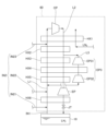
- FIG. 1 is a diagram showing an example of a liquid hydrogen transfer system 1.
- the liquid hydrogen transfer system 1 includes liquid hydrogen storage tanks 10 and 20, transfer pipes 30 and 40, an insulated valve box 50, and a reliquefaction device 60.
- the liquid hydrogen storage tank 10 stores liquid hydrogen.
- the liquid hydrogen storage tank 10 is installed in a facility for storing liquid hydrogen on the ground L adjacent to the quay Q.
- the liquid hydrogen storage tank 20 stores liquid hydrogen.
- the liquid hydrogen storage tank 20 is mounted on a ship SP docked at a quay Q.
- the transfer pipes 30 and 40 are pipes that transfer liquid hydrogen between the liquid hydrogen storage tank 10 and the liquid hydrogen storage tank 20.
- the transfer pipes 30 and 40 have a heat insulating structure as described below.
- the term "insulation" includes not only a state in which no heat flows in or out, but also a state in which heat flow is suppressed more than in a pipe with a normal structure, and will be used hereinafter with the same intent.
- the transfer pipe 30 is used to transfer liquid hydrogen from the liquid hydrogen storage tank 10 to the liquid hydrogen storage tank 20.
- the transfer pipe 30 is used when the ship SP stores liquid hydrogen in the liquid hydrogen storage tank 20 and transports it to the outside.
- the transfer pipe 30 is connected to the liquid hydrogen storage tank 20 at one end, and branches into transfer pipes 30-1 and 30-2 at the other end.
- the tip of the transfer pipe 30-1 is connected to the liquid hydrogen storage tank 10.
- the tip of the transfer pipe 30-2 is connected to the heat insulating valve box 50.
- the transfer pipe 30 includes a liquid hydrogen flow path 31 and a BOG flow path 32.
- the liquid hydrogen flow path 31 has one end connected to the liquid hydrogen storage tank 20 and the other end connected to the bottom of the liquid hydrogen storage tank 10 in a manner that is included in the transfer pipe 30-1. Transfer liquid hydrogen to storage tank 20.
- the BOG flow path 32 has one end connected to the liquid hydrogen storage tank 20 and the other end connected to the insulated valve box 50 in a manner that is included in the transfer pipe 30-2, and connects the insulated valve box 50 from the liquid hydrogen storage tank 20.
- the boil-off gas (BOG) is transferred to the reliquefaction device 60 via the boil-off gas (BOG).
- BOG boil-off gas
- a heat shielding effect utilizing the sensible heat of the cryogenic boil-off gas flowing through the BOG flow path 32 arranged along the liquid hydrogen flow path 31 allows the liquid hydrogen in the liquid hydrogen flow path 31 to be exposed to the outside. It is possible to suppress the amount of heat intrusion from the inside. As a result, the amount of gasified liquid hydrogen can be reduced and energy loss can be suppressed.
- the boil-off gas in the liquid hydrogen storage tank 20 includes boil-off gas generated during the transfer of liquid hydrogen through the liquid hydrogen flow path 31 and boil-off gas generated inside the liquid hydrogen storage tank 20.
- the boil-off gas generated during the transfer of liquid hydrogen includes gas generated by a flash caused by heat input from the outside and gas generated by a flash caused by a pressure difference.
- Gases generated due to a flush caused by a pressure difference include a flash caused by a pressure loss in the liquid hydrogen flow path 31, a flash caused by a valve passed during transfer, and a gas generated when flowing from the liquid hydrogen flow path 31 into the liquid hydrogen storage tank 20. Includes gas generated by flash etc. associated with expansion.
- the boil-off gas generated inside the liquid hydrogen storage tank 20 includes all types of evaporation gas, including evaporation gas generated by the heat of transition associated with the conversion of orthohydrogen, which is a nuclear spin isomer of hydrogen, to parahydrogen (ortho-para equilibrium conversion). Contains gas.
- the transfer pipe 40 is used to transfer liquid hydrogen from the liquid hydrogen storage tank 20 to the liquid hydrogen storage tank 10.
- the transfer pipe 40 is used when the ship SP docks at the quay Q with liquid hydrogen stored in the liquid hydrogen storage tank 20.
- One end of the transfer pipe 40 is connected to the bottom of the liquid hydrogen storage tank 20, and the other end is connected to the heat insulating valve box 50.
- the transfer pipe 40 includes a liquid hydrogen flow path 41 and BOG flow paths 42 and 43.
- the liquid hydrogen flow path 41 has one end connected to the bottom of the liquid hydrogen storage tank 20 and the other end connected to the liquid hydrogen storage tank 10 via the inside of the insulated valve box 50, and is connected to the liquid hydrogen storage tank 10 from the liquid hydrogen storage tank 20 to the liquid hydrogen storage tank 20. Transfer liquid hydrogen to 10.
- the BOG flow path 42 has one end connected to the liquid hydrogen storage tank 20 and the other end connected to the adiabatic valve box 50, and supplies boil-off gas from the liquid hydrogen storage tank 20 to the reliquefaction device 60 via the adiabatic valve box 50. Transport.
- a heat shielding effect utilizing the sensible heat of the cryogenic boil-off gas flowing through the BOG flow path 42 arranged along the liquid hydrogen flow path 41 allows the liquid hydrogen in the liquid hydrogen flow path 41 to be exposed to the outside. It is possible to suppress the amount of heat intrusion from the inside. As a result, the amount of gasified liquid hydrogen can be reduced and energy loss can be suppressed.
- a valve 42V is provided in the BOG flow path 42.
- the valve 42V can open and close the BOG channel 42.
- the BOG flow path 43 has one end connected to the middle part of the BOG flow path 42 and the other end connected to the liquid hydrogen storage tank 10 via an insulated valve box 50, so that the BOG flow path 43 is connected to the BOG flow path 42 from the liquid hydrogen storage tank 10.
- the boil-off gas in the liquid hydrogen storage tank 10 is transferred and merged.
- a heat shielding effect utilizing the sensible heat of the cryogenic boil-off gas flowing through the BOG flow path 43 arranged along the liquid hydrogen flow path 41 allows the liquid hydrogen in the liquid hydrogen flow path 41 to be exposed to the outside. It is possible to suppress the amount of heat intrusion from the inside. As a result, the amount of gasified liquid hydrogen can be reduced and energy loss can be suppressed.
- the BOG flow path 43 is connected to the BOG flow path 42 on the side closer to the insulation valve box 50 (reliquefaction device 60) than the valve 42V of the BOG flow path 42.
- the valve 42V when the valve 42V is closed, only the boil-off gas in the liquid hydrogen storage tank 10 is allowed to flow through the BOG channels 42 and 43, thereby preventing heat from entering the liquid hydrogen in the liquid hydrogen channel 41 from the outside.
- the amount can be controlled. As a result, the amount of gasified liquid hydrogen can be reduced and energy loss can be suppressed.
- the transfer pipe 30 may also be provided with a BOG flow path that causes the boil-off gas from the liquid hydrogen storage tank 10 to join the BOG flow path 32.
- the boil-off gas in the liquid hydrogen storage tank 10 includes boil-off gas generated during transfer of liquid hydrogen through the liquid hydrogen flow path 41 and boil-off gas generated inside the liquid hydrogen storage tank 10.
- the boil-off gas generated during the transfer of liquid hydrogen includes gas generated by a flash caused by heat input from the outside and gas generated by a flash caused by a pressure difference.
- Gas generated due to a pressure difference includes a flash caused by a pressure loss in the liquid hydrogen flow path 41, a flash caused by a valve passed during transfer, and a gas generated when the liquid hydrogen flows into the liquid hydrogen storage tank 10 from the liquid hydrogen flow path 41. Includes gas generated by flash etc. associated with expansion.
- the boil-off gas generated inside the liquid hydrogen storage tank 10 includes all evaporation gases including evaporation gas generated by the heat of transition accompanying the conversion of orthohydrogen, which is a nuclear spin isomer of hydrogen, to parahydrogen (ortho-para equilibrium conversion). Contains gas.
- the insulating valve box 50 is installed in a facility for storing liquid hydrogen on the ground L, and inputs the boil-off gas transferred through the BOG channels 32 and 42 to the reliquefaction device 60.
- the heat insulating valve box 50 is installed, for example, above the liquid hydrogen storage tank 20.
- the heat insulating valve box 50 has a heat insulating structure and can suppress heat from entering into the liquid hydrogen and boil-off gas in each flow path passing through the inside.
- the heat insulating valve box 50 selectively inputs the boil-off gas transferred from the BOG channels 32 and 42 to one of the plurality of input paths of the reliquefaction device 60.
- the adiabatic valve box includes a plurality of flow paths connected to a plurality of input paths, and a valve group for selectively allowing boil-off gas to flow into any one of the plurality of flow paths.
- the reliquefaction device 60 is installed in a facility for storing liquid hydrogen on the ground L, and reliquefies the boil-off gas in the liquid hydrogen storage tank 10 and the liquid hydrogen storage tank 20. Liquid hydrogen output from the reliquefaction device 60 is returned to the liquid hydrogen storage tank 10.
- the heat insulating valve box 50 and the reliquefaction device 60 may be omitted.
- the boil-off gas in the BOG channels 32, 42 is used to suppress the amount of heat entering from the outside into the liquid hydrogen in the liquid hydrogen channels 31, 41, and then is released into the atmosphere.
- equipment that can directly consume the boil-off gas as a gas as fuel or the like may be provided.
- FIGS. 2 and 3 are cross-sectional views showing an example of the transfer pipe 30. Specifically, FIGS. 2 and 3 are cross-sectional views of different parts of an example of the transfer pipe 30.
- the transfer tube 30 includes an outer tube 30A, a shield inner tube 30B, and transfer tubes 30C and 30D.
- the outer tube 30A corresponds to the outer shape of the transfer tube 30, and has, for example, a circular cross section.
- the shield inner tube 30B is provided inside the outer tube 30A so that the radiant heat input from the outer tube 30A is not directly transmitted to the transfer tube 30C.
- the shield inner tube 30B has a smaller outer diameter than the outer tube 30A and has a circular cross section that is substantially concentric with the outer tube 30A.
- substantially means, for example, to allow manufacturing errors and manufacturing limits, and will be used hereinafter with the same meaning.
- spacers 30F are provided at predetermined intervals in the direction in which the transfer tube 30 extends. Thereby, the position of the shield inner tube 30B can be maintained in the vacuum heat insulating layer inside the outer tube 30A.
- the space SP1 between the outer tube 30A and the shield inner tube 30B is, for example, in a substantially vacuum state.
- the transfer pipe 30C is provided inside the shield inner tube 30B so that the radiation and intrusion heat from the outer tube 30A and the shield inner tube 30B is not directly transmitted.
- the transfer tube 30C has a circular cross section that has a smaller outer diameter than the shield inner tube 30B and is substantially concentric with the outer tube 30A and the shield inner tube 30B.
- the inside of the transfer pipe 30C corresponds to the liquid hydrogen channel 31, and liquid hydrogen flows therethrough.
- spacers 30G are provided at predetermined intervals in the direction in which the transfer tube 30 extends. Thereby, the position of the transfer tube 30C can be maintained in the vacuum heat insulating layer inside the shield inner tube 30B.
- the space SP2 between the shield inner tube 30B and the transfer tube 30C is, for example, in a substantially vacuum state. Thereby, it is possible to suppress the heat input from the outer tube 30A and the shield inner tube 30B to the transfer tube 30C, and to suppress the amount of heat intrusion into the liquid hydrogen transferred by the transfer tube 30C. Therefore, the amount of gasified liquid hydrogen can be reduced and energy loss can be suppressed.
- the transfer pipe 30D is arranged in thermal contact with the shield inner pipe 30B.
- the transfer tube 30D has a circular cross section with a smaller outer diameter than the shield inner tube 30B.
- the inside of the transfer pipe 30D corresponds to the BOG channel 32, and has a cross-sectional inner diameter sufficient to allow the boil-off gas to flow therethrough.
- the transfer pipe 30D is attached to the shield inner pipe 30B, for example. Specifically, a portion of the shield inner tube 30B in the circumferential direction may be cut out, and the transfer tube 30D may be fixed by being fitted into the cutout portion. As a result, the inner shield tube 30B is maintained at an effective radiation shielding temperature by the action of the transfer tube 30D through which the extremely low temperature boil-off gas flows, and as a result, the liquid hydrogen in the transfer tube 30C inside the shield inner tube 30B is The amount of heat intrusion can be further suppressed. Therefore, the amount of gasified liquid hydrogen can be further reduced, and energy loss can be further suppressed.
- a plurality of (in this example, two) transfer pipes 30D are provided.
- the positions of the plurality of transfer pipes 30D in the circumferential direction are optimally determined depending on the temperature level of the boil-off gas flowing through each pipe.
- two transfer pipes 30D are arranged at intervals of 180 degrees in the circumferential direction.
- spacers 30H are provided at predetermined intervals between the outer tube 30A and the transfer tube 30D in the direction in which the transfer tube 30 extends. Thereby, the shield inner tube 30B can be held in the vacuum insulation layer inside the outer tube 30A via the transfer tube 30.
- transfer pipe 40 the inside of a pipe similar to the transfer pipe 30D (hereinafter referred to as "transfer pipe 40D" for convenience) corresponds to either the BOG channel 42 or 43. Therefore, in the case of the transfer pipe 40, some of the transfer pipes 40D among the plurality of transfer pipes 40D correspond to the BOG flow path 42, and the remaining part of the transfer pipes 40D correspond to the BOG flow path 43. It's okay to be.
- the transfer tube 30C can be double vacuum insulated by the shield inner tube 30B, and the shield inner tube 30B can be maintained at an effective radiation shielding temperature by the boil-off gas of the transfer tube 30D. can. Therefore, the amount of heat entering into the liquid hydrogen flowing through the transfer pipe 30C inside the shield inner pipe 30B can be suppressed, and as a result, the amount of liquid hydrogen gasified can be reduced and energy loss can be suppressed. can.
- FIG. 4 is a diagram schematically showing an example of the configuration of a reliquefaction device. Specifically, FIG. 4 illustrates the Claude cycle as an example of a process with relatively high liquefaction efficiency.
- the reliquefaction device 60 also requires components such as a low-temperature catalyst tank to accelerate the conversion of orthohydrogen to parahydrogen during hydrogen gas liquefaction. becomes. Furthermore, the reliquefaction device 60 includes various methods, such as a method in which other liquefied gas (for example, liquid helium, etc.) is incorporated as an auxiliary refrigerant, and a separate Brighton method in which the turbine circuit and the liquefaction circuit are completely separated. May be applied arbitrarily.
- other liquefied gas for example, liquid helium, etc.
- the reliquefaction device 60 includes paths L1 to L3, a compressor CP, heat exchangers HX1 to HX6, a supercritical expansion turbine EP, a Joule-Thompson valve JT, an expansion turbine EP3, and low pressure returns IN1 and IN2. liquefaction path OUT.
- the path L1 sends the liquefied circulating gas and boil-off gas (hydrogen gas) input through the low-pressure returns IN1 and IN2 to the suction side of the compressor CP.
- boil-off gas hydrogen gas
- Path L1 passes through heat exchanger HX6, heat exchanger HX5, heat exchanger HX4, heat exchanger HX3, heat exchanger HX2, and heat exchanger HX1 in order from the cryogenic side (upstream side), and passes through heat exchanger HX6, heat exchanger HX5, heat exchanger HX4, heat exchanger HX3, heat exchanger HX2, and heat exchanger HX1, and Connected to CP.
- route L2 hydrogen gas mechanically compressed by external energy by compressor CP is cooled with hydrogen gas (low pressure return gas) in route L1 through heat exchangers HX1 to HX6, and finally, the hydrogen gas is cooled by the hydrogen gas (low pressure return gas) of route L1,
- the expansion circulates a portion of the hydrogen gas to liquefy it.
- Path L2 includes, in order from the high temperature side (upstream side), heat exchanger HX1, heat exchanger HX2, heat exchanger HX3, heat exchanger HX4, heat exchanger HX5, supercritical expansion turbine, heat exchanger HX6, and Joule. Passing Thomson Valve JT.
- Route L3 branches hydrogen gas from a location between heat exchangers HX2 and HX3 in route L2, and uses the hydrogen gas whose temperature has been lowered through adiabatic expansion by expansion turbine EP3 to cool the heat exchanger in route L1. It is made to join at a location between HX6 and heat exchanger HX5.
- the compressor CP adiabatically compresses the hydrogen gas supplied from the route L1 and discharges it to the route L2.
- the heat exchanger HX1 uses hydrogen gas at a relatively low temperature on the upstream side of the route L1 and liquid nitrogen supplied from the outside, and a relatively high temperature immediately after being mechanically compressed by the compressor CP on the route L2. Heat exchange is performed with hydrogen gas. Thereby, the hydrogen gas in the path L2 can be sequentially cooled.
- the heat exchanger HX2 performs heat exchange between the hydrogen gas in the path L1, which has a relatively low temperature, and the hydrogen gas, which has a relatively high temperature in the path L2. Thereby, the hydrogen gas in the path L2 after passing through the heat exchanger HX1 can be further cooled.
- the heat exchanger HX3 performs heat exchange between the relatively low temperature hydrogen gas in the path L1 and the relatively high temperature hydrogen gas in the path L2. Thereby, the hydrogen gas in the path L2 after passing through the heat exchanger HX2 can be further cooled.
- the heat exchanger HX4 exchanges relatively low-temperature hydrogen gas in the path L1, relatively low-temperature hydrogen gas adiabatically expanded in the expansion turbine EP31 in the path L3, and relatively low-temperature hydrogen gas in the upstream side of the path L2. It exchanges heat with hydrogen gas, which has a high Thereby, the hydrogen gas in the path L2 after passing through the heat exchanger HX3 can be further cooled.
- the heat exchanger HX5 exchanges heat between the relatively low-temperature hydrogen gas in the route L1 and the relatively high-temperature hydrogen gas on the upstream side of the route L2. Thereby, the hydrogen gas in the path L2 after passing through the heat exchanger HX4 can be further cooled.
- the heat exchanger HX6 performs heat exchange between the relatively low temperature hydrogen gas in the path L1 and the relatively high temperature hydrogen gas in the path L2. Thereby, the hydrogen gas adiabatically expanded by the supercritical expansion turbine EP can be further cooled.
- the supercritical expansion turbine EP is provided between the heat exchanger HX5 and the heat exchanger HX6 in the path L2, and lowers the temperature by adiabatically expanding the hydrogen gas that has passed through the heat exchanger HX5. supply to.
- the Joule-Thomson valve JT performs isenthalpic expansion of the hydrogen gas output from the heat exchanger HX6 in the path L2. At this time, since the temperature of the hydrogen gas supplied to the Joule-Thompson valve JT is below the reversal temperature, a temperature drop occurs due to isenthalpic expansion. Thereby, the Joule-Thomson valve JT can liquefy a portion of the hydrogen gas, output it to the liquefaction path OUT, and return the liquid hydrogen to the liquid hydrogen storage tank 10.
- the expansion turbine EP3 is provided on the path L3 as described above.
- Expansion turbine EP3 includes expansion turbines EP31 and EP32.
- the expansion turbine EP3 adiabatically expands the hydrogen gas in the path L3 and causes it to flow back into the path L1. Thereby, the amount of refrigeration required for the path L1, which is the low temperature side of the heat exchangers HX1 to HX5, can be generated.
- the expansion turbine EP31 adiabatically expands the hydrogen gas at the most upstream side of the path L3. Thereby, the temperature of the hydrogen gas after passing through the heat exchanger HX2 on the route L2 can be further lowered, and the hydrogen gas can be supplied to the downstream side of the route L3 (heat exchanger HX4).
- the expansion turbine EP32 adiabatically expands the hydrogen gas output from the heat exchanger HX4 on the path L3. Thereby, the temperature of the hydrogen gas can be further lowered, and the hydrogen gas having a relatively low temperature can be refluxed to the path L1. Therefore, the necessary amount of cooling can be secured on the low temperature side (path L1) of the heat exchangers HX1 to HX5.
- the low pressure return IN1 is used to input the boil-off gas (hydrogen gas) from the liquid hydrogen storage tank 10 to the reliquefaction device 60 (path L1).
- the low pressure return IN2 is used to input the boil-off gas from the liquid hydrogen storage tank 20, which is transferred through the BOG channels 32 and 42, to the low temperature side (path L1) of the reliquefaction device 60.
- the low pressure return IN2 includes low pressure returns IN21 to IN23.
- the low pressure return IN21 is used to inject the boil-off gas from the liquid hydrogen storage tank 20, which is transferred through the BOG channels 32 and 42, into the upstream side of the lowest temperature (most upstream) heat exchanger HX6 in the path L1. .
- the low pressure return IN22 is used to inject the boil-off gas from the liquid hydrogen storage tank 20, which is transferred through the BOG channels 32 and 42, between the heat exchanger HX6 and the heat exchanger HX5 in the path L1.
- the low pressure return IN23 is used to inject the boil-off gas from the liquid hydrogen storage tank 20, which is transferred through the BOG channels 32 and 42, between the heat exchanger HX2 and the heat exchanger HX1 in the path L1.
- the control device that controls the valve group of the heat insulating valve box 50 may be installed at any location.
- the control device may be mounted on the reliquefaction device 60, the heat insulating valve box 50, or a liquid hydrogen storage facility on the ground L.
- the control device controls the valve group according to the temperature state of the boil-off gas transferred through the BOG channels 32 and 42, and selectively utilizes any one of the low pressure returns IN21 to IN23.
- the temperature state of the boil-off gas transferred through the BOG channels 32 and 42 is measured, for example, by a temperature sensor provided in the heat insulating valve box 50, and the measurement result is taken into the control device.
- the temperature region of the boil-off gas may be divided into a first region to a third region from the lowest temperature region.
- the control device then uses the low pressure return IN 21 when the temperature of the boil-off gas is in the first region, uses the low pressure return IN 22 when it is in the second region, and uses the low pressure return IN 22 when the temperature of the boil-off gas is in the third region.
- Return IN23 may be used.
- the control device can appropriately select the route for introducing the boil-off gas into the route L1 in accordance with the temperature of the hydrogen gas that increases toward the downstream side of the route L1.
- the control device selectively utilizes any one of the low pressure returns IN21 to IN23, further considering the temperature state of the boil-off gas in the liquid hydrogen storage tank 10 that is introduced into the path L1 through the low pressure return IN1. It's okay.
- the temperature state of the boil-off gas in the liquid hydrogen storage tank 10 is measured, for example, by a temperature sensor installed in the liquid hydrogen storage tank 10, and the measurement result is taken into the control device.
- the temperature range (first range to third range) of the boil-off gas is varied depending on the temperature state of the boil-off gas in the liquid hydrogen storage tank 10.
- the control device can appropriately select the route for introducing the boil-off gas into the route L1 in accordance with the temperature state of the boil-off gas in the liquid hydrogen storage tank that is dominant with respect to the temperature state of the route L1.
- the low-pressure return IN2 may include only one or two input paths through which boil-off gas from the liquid hydrogen storage tank 20 can be input, or may include four or more input paths.
- the liquefaction path OUT outputs liquid hydrogen output from the Joule-Thomson valve JT toward the liquid hydrogen storage tank 10.
- the reliquefaction device 60 shows an example of a circuit that can reliquefy the boil-off gas in the liquid hydrogen storage tanks 10 and 20 and return it to the liquid hydrogen storage tank 10.
- the reliquefaction device 60 adds liquid hydrogen to the hydrogen gas before adiabatic compression, which is used for cooling the hydrogen gas after adiabatic compression, according to the temperature state of the boil-off gas transferred from the liquid hydrogen storage tank 20.
- the position where the boil-off gas in the storage tank 20 is merged is changed. This makes it possible to select an operation that always optimizes the liquefaction efficiency.
- heat input from the outside may vaporize the liquid hydrogen and generate boil-off gas.
- liquid hydrogen is not in an equilibrium component ratio of ortho-hydrogen and para-hydrogen in the liquid hydrogen transfer channel or storage area at the transfer destination, ortho-para equilibrium conversion will proceed, and the heat of the transition will Furthermore, gasification of liquid hydrogen may proceed.
- the liquid hydrogen being transferred may A large amount of boil-off gas is generated due to the pre-cooling of the tube.
- the liquid hydrogen transfer system 1 includes a first storage section, a second storage section, a pipe section, a first flow path, and a second flow path.
- the first storage section is, for example, a liquid hydrogen storage tank 10.
- the second storage section is, for example, a liquid hydrogen storage tank 20.
- the pipe portion is, for example, the transfer pipe 30 or the transfer pipe 40.
- the first channel is, for example, the liquid hydrogen channel 31 or the liquid hydrogen channel 41.
- the second flow path is, for example, the BOG flow path 32 or the BOG flow paths 42 and 43.
- the first storage section stores liquid hydrogen.
- the second storage section stores liquid hydrogen.
- the pipe portion connects the first storage portion and the second storage portion.
- first flow path is provided inside the pipe section and is configured to be able to transfer liquid hydrogen between the first storage section and the second storage section.
- the second flow path is provided inside the pipe section, and outputs boil-off gas in which liquid hydrogen is vaporized from at least one of the first storage section and the second storage section to the outside.
- the liquid hydrogen transfer system 1 utilizes the boil-off gas in the first storage section and the second storage section to eliminate boil-off gas that accompanies the transfer of liquid hydrogen between the first storage section and the second storage section. Gas generation can be suppressed.
- the first storage section and the second storage section may contain boil-off gas caused by inevitable flash gas caused by a pressure difference during transfer of liquid hydrogen. Therefore, it is possible to stably suppress the generation of boil-off gas that accompanies the transfer of liquid hydrogen between the first storage section and the second storage section by using boil-off gas that cannot be reduced to zero. can.
- the tube portion may include a first tube portion corresponding to the outer shape and a second tube portion disposed inside the first tube portion.
- the first tube portion is, for example, the outer tube 30A.
- the second tube portion is, for example, the shield inner tube 30B.
- the first flow path may be provided inside the second tube section, and the second flow path may be attached along the second tube section.
- the liquid hydrogen transfer system 1 cools the second pipe section by the boil-off gas in the second flow path, and increases the temperature of the liquid hydrogen in the first flow path disposed inside the second pipe section. can be suppressed.
- the liquid hydrogen transfer system 1 may include a liquefaction section that liquefies the boil-off gas transferred through the second flow path.
- the liquefaction section is, for example, the reliquefaction device 60.
- the liquid hydrogen transfer system 1 can re-liquefy the boil-off gas and use it as liquid hydrogen without discharging it into the atmosphere.
- Liquid hydrogen transfer system 10 Liquid hydrogen storage tank (first storage section) 20 Liquid hydrogen storage tank (second storage section) 30, 30-1, 30-2 Transfer pipe (pipe section) 30A outer tube (first tube part) 30B Shield inner tube (second tube part) 30C Transfer pipe 30D Transfer pipe 30F Spacer 30G Spacer 30H Spacer 31 Liquid hydrogen channel (first channel) 32 BOG channel (second channel) 40 Transfer pipe (pipe section) 41 Liquid hydrogen channel (first channel) 42 BOG channel (second channel) 42V valve 43 BOG flow path (second flow path) 50 Insulated valve box 60 Reliquefaction device (liquefaction section) CP Compressor EP Supercritical expansion turbine EP3, EP31, EP32 Expansion turbine HX1 to HX6 Heat exchanger IN1 Low pressure return IN2, IN21 to IN23 Low pressure return JT Joule-Thomson valve L1 to L3 Path OUT Liquefaction path
Landscapes
- Engineering & Computer Science (AREA)
- Mechanical Engineering (AREA)
- General Engineering & Computer Science (AREA)
- Filling Or Discharging Of Gas Storage Vessels (AREA)
Priority Applications (1)
| Application Number | Priority Date | Filing Date | Title |
|---|---|---|---|
| JP2024520459A JPWO2023219083A1 (https=) | 2022-05-11 | 2023-05-09 |
Applications Claiming Priority (2)
| Application Number | Priority Date | Filing Date | Title |
|---|---|---|---|
| JP2022078401 | 2022-05-11 | ||
| JP2022-078401 | 2022-05-11 |
Publications (1)
| Publication Number | Publication Date |
|---|---|
| WO2023219083A1 true WO2023219083A1 (ja) | 2023-11-16 |
Family
ID=88730263
Family Applications (1)
| Application Number | Title | Priority Date | Filing Date |
|---|---|---|---|
| PCT/JP2023/017457 Ceased WO2023219083A1 (ja) | 2022-05-11 | 2023-05-09 | 液体水素移送システム |
Country Status (2)
| Country | Link |
|---|---|
| JP (1) | JPWO2023219083A1 (https=) |
| WO (1) | WO2023219083A1 (https=) |
Cited By (1)
| Publication number | Priority date | Publication date | Assignee | Title |
|---|---|---|---|---|
| US20240309980A1 (en) * | 2023-03-17 | 2024-09-19 | H2CREO Corp. | Two-way twin-axial connector module of a receptacle for transporting liquefied gas and liquefied gas transport system including the same |
Citations (4)
| Publication number | Priority date | Publication date | Assignee | Title |
|---|---|---|---|---|
| JPS5676800A (en) * | 1979-11-27 | 1981-06-24 | Sumitomo Heavy Ind Ltd | Liquid hydrogen storage tank equipped with para-ortho hydrogen converter |
| JP2007255670A (ja) * | 2006-03-24 | 2007-10-04 | Toyota Motor Corp | 液化ガス充填ノズル、液化ガス充填装置及び液化ガス充填方法 |
| US20150219243A1 (en) * | 2010-12-30 | 2015-08-06 | Rakesh Kumar | Cryogenic fluid transfer tunnel assembly and uses thereof |
| JP2022502616A (ja) * | 2018-10-09 | 2022-01-11 | レール・リキード−ソシエテ・アノニム・プール・レテュード・エ・レクスプロワタシオン・デ・プロセデ・ジョルジュ・クロード | 液化水素を貯蔵及び分配するための方法並びに設備 |
-
2023
- 2023-05-09 JP JP2024520459A patent/JPWO2023219083A1/ja active Pending
- 2023-05-09 WO PCT/JP2023/017457 patent/WO2023219083A1/ja not_active Ceased
Patent Citations (4)
| Publication number | Priority date | Publication date | Assignee | Title |
|---|---|---|---|---|
| JPS5676800A (en) * | 1979-11-27 | 1981-06-24 | Sumitomo Heavy Ind Ltd | Liquid hydrogen storage tank equipped with para-ortho hydrogen converter |
| JP2007255670A (ja) * | 2006-03-24 | 2007-10-04 | Toyota Motor Corp | 液化ガス充填ノズル、液化ガス充填装置及び液化ガス充填方法 |
| US20150219243A1 (en) * | 2010-12-30 | 2015-08-06 | Rakesh Kumar | Cryogenic fluid transfer tunnel assembly and uses thereof |
| JP2022502616A (ja) * | 2018-10-09 | 2022-01-11 | レール・リキード−ソシエテ・アノニム・プール・レテュード・エ・レクスプロワタシオン・デ・プロセデ・ジョルジュ・クロード | 液化水素を貯蔵及び分配するための方法並びに設備 |
Cited By (2)
| Publication number | Priority date | Publication date | Assignee | Title |
|---|---|---|---|---|
| US20240309980A1 (en) * | 2023-03-17 | 2024-09-19 | H2CREO Corp. | Two-way twin-axial connector module of a receptacle for transporting liquefied gas and liquefied gas transport system including the same |
| US12429157B2 (en) * | 2023-03-17 | 2025-09-30 | H2CREO Corp. | Two-way twin-axial connector module of a receptacle for transporting liquefied gas and liquefied gas transport system including the same |
Also Published As
| Publication number | Publication date |
|---|---|
| JPWO2023219083A1 (https=) | 2023-11-16 |
Similar Documents
| Publication | Publication Date | Title |
|---|---|---|
| JP6021430B2 (ja) | 液体水素貯槽から発生するボイルオフガスの再液化方法 | |
| US8739569B2 (en) | Liquefied gas reliquefier, liquefied-gas storage facility and liquefied-gas transport ship including the same, and liquefied-gas reliquefaction method | |
| JP5890748B2 (ja) | 液体水素製造装置 | |
| CN107848607B (zh) | 船舶、船舶的蒸发气体处理系统及其方法 | |
| JP7488093B2 (ja) | 液化水素製造設備 | |
| KR101524430B1 (ko) | 증발가스 재액화장치 | |
| JP2023520766A (ja) | 液化及び過冷却システム並びに方法 | |
| WO2023219083A1 (ja) | 液体水素移送システム | |
| KR20240143887A (ko) | 수소 액화 시스템 및 수소 액화 방법 | |
| JP7841673B2 (ja) | 液化装置、液化システム、水素ガス充填システム | |
| CN115096013B (zh) | 一种实现氦低温制冷机快速降温的装置及方法 | |
| US20180216876A1 (en) | Apparatus and method for boil-off gas reliquefaction | |
| KR20230076415A (ko) | 선박의 증발가스 재액화 시스템 및 재액화 시스템용 열교환기 | |
| JP2024017052A (ja) | 液体水素移送システム | |
| KR20190071180A (ko) | 선박용 증발가스 재액화 시스템 및 방법 | |
| CN118176149A (zh) | 船舶再液化系统的渗漏检测系统 | |
| JP2945806B2 (ja) | 液化冷凍装置に設けられる冷凍負荷の予冷装置 | |
| JP7675289B2 (ja) | 船舶用再液化システムの微少漏洩検知システム | |
| Rode et al. | Operation of the Tevatron six-kilometer-long transfer line | |
| CN118159467A (zh) | 船舶再液化系统的排气方法 | |
| KR20250102216A (ko) | 선박의 증발가스 재액화 시스템 및 방법 | |
| KR20250171686A (ko) | 선박의 카고탱크 압력제어시스템 | |
| KR20180054333A (ko) | 증발가스 재액화 시스템 및 방법 | |
| WO2022209850A1 (ja) | 抑制装置および抑制方法 | |
| Quack et al. | The TESLA cryo-plants |
Legal Events
| Date | Code | Title | Description |
|---|---|---|---|
| 121 | Ep: the epo has been informed by wipo that ep was designated in this application |
Ref document number: 23803560 Country of ref document: EP Kind code of ref document: A1 |
|
| DPE1 | Request for preliminary examination filed after expiration of 19th month from priority date (pct application filed from 20040101) | ||
| WWE | Wipo information: entry into national phase |
Ref document number: 2024520459 Country of ref document: JP |
|
| NENP | Non-entry into the national phase |
Ref country code: DE |
|
| 122 | Ep: pct application non-entry in european phase |
Ref document number: 23803560 Country of ref document: EP Kind code of ref document: A1 |