WO2023218935A1 - イメージセンサ、情報処理方法、プログラム - Google Patents
イメージセンサ、情報処理方法、プログラム Download PDFInfo
- Publication number
- WO2023218935A1 WO2023218935A1 PCT/JP2023/016161 JP2023016161W WO2023218935A1 WO 2023218935 A1 WO2023218935 A1 WO 2023218935A1 JP 2023016161 W JP2023016161 W JP 2023016161W WO 2023218935 A1 WO2023218935 A1 WO 2023218935A1
- Authority
- WO
- WIPO (PCT)
- Prior art keywords
- image
- processing
- model
- inference
- processing unit
- Prior art date
- Legal status (The legal status is an assumption and is not a legal conclusion. Google has not performed a legal analysis and makes no representation as to the accuracy of the status listed.)
- Ceased
Links
Images


















Classifications
-
- G—PHYSICS
- G06—COMPUTING OR CALCULATING; COUNTING
- G06V—IMAGE OR VIDEO RECOGNITION OR UNDERSTANDING
- G06V10/00—Arrangements for image or video recognition or understanding
- G06V10/10—Image acquisition
- G06V10/12—Details of acquisition arrangements; Constructional details thereof
- G06V10/14—Optical characteristics of the device performing the acquisition or on the illumination arrangements
- G06V10/147—Details of sensors, e.g. sensor lenses
-
- G—PHYSICS
- G06—COMPUTING OR CALCULATING; COUNTING
- G06V—IMAGE OR VIDEO RECOGNITION OR UNDERSTANDING
- G06V10/00—Arrangements for image or video recognition or understanding
- G06V10/94—Hardware or software architectures specially adapted for image or video understanding
- G06V10/95—Hardware or software architectures specially adapted for image or video understanding structured as a network, e.g. client-server architectures
-
- G—PHYSICS
- G06—COMPUTING OR CALCULATING; COUNTING
- G06V—IMAGE OR VIDEO RECOGNITION OR UNDERSTANDING
- G06V10/00—Arrangements for image or video recognition or understanding
- G06V10/96—Management of image or video recognition tasks
-
- H—ELECTRICITY
- H04—ELECTRIC COMMUNICATION TECHNIQUE
- H04N—PICTORIAL COMMUNICATION, e.g. TELEVISION
- H04N23/00—Cameras or camera modules comprising electronic image sensors; Control thereof
- H04N23/60—Control of cameras or camera modules
-
- H—ELECTRICITY
- H04—ELECTRIC COMMUNICATION TECHNIQUE
- H04N—PICTORIAL COMMUNICATION, e.g. TELEVISION
- H04N25/00—Circuitry of solid-state image sensors [SSIS]; Control thereof
- H04N25/70—SSIS architectures; Circuits associated therewith
-
- G—PHYSICS
- G06—COMPUTING OR CALCULATING; COUNTING
- G06V—IMAGE OR VIDEO RECOGNITION OR UNDERSTANDING
- G06V10/00—Arrangements for image or video recognition or understanding
- G06V10/70—Arrangements for image or video recognition or understanding using pattern recognition or machine learning
- G06V10/82—Arrangements for image or video recognition or understanding using pattern recognition or machine learning using neural networks
-
- G—PHYSICS
- G06—COMPUTING OR CALCULATING; COUNTING
- G06V—IMAGE OR VIDEO RECOGNITION OR UNDERSTANDING
- G06V20/00—Scenes; Scene-specific elements
- G06V20/50—Context or environment of the image
- G06V20/52—Surveillance or monitoring of activities, e.g. for recognising suspicious objects
- G06V20/54—Surveillance or monitoring of activities, e.g. for recognising suspicious objects of traffic, e.g. cars on the road, trains or boats
-
- G—PHYSICS
- G06—COMPUTING OR CALCULATING; COUNTING
- G06V—IMAGE OR VIDEO RECOGNITION OR UNDERSTANDING
- G06V20/00—Scenes; Scene-specific elements
- G06V20/70—Labelling scene content, e.g. deriving syntactic or semantic representations
-
- G—PHYSICS
- G06—COMPUTING OR CALCULATING; COUNTING
- G06V—IMAGE OR VIDEO RECOGNITION OR UNDERSTANDING
- G06V2201/00—Indexing scheme relating to image or video recognition or understanding
- G06V2201/07—Target detection
-
- G—PHYSICS
- G06—COMPUTING OR CALCULATING; COUNTING
- G06V—IMAGE OR VIDEO RECOGNITION OR UNDERSTANDING
- G06V2201/00—Indexing scheme relating to image or video recognition or understanding
- G06V2201/08—Detecting or categorising vehicles
-
- G—PHYSICS
- G06—COMPUTING OR CALCULATING; COUNTING
- G06V—IMAGE OR VIDEO RECOGNITION OR UNDERSTANDING
- G06V40/00—Recognition of biometric, human-related or animal-related patterns in image or video data
- G06V40/10—Human or animal bodies, e.g. vehicle occupants or pedestrians; Body parts, e.g. hands
Definitions
- the present technology relates to the technical field of image sensors, information processing methods, and programs that perform inference processing using artificial intelligence models.
- Some image sensors of camera devices are capable of inference processing by deploying an artificial intelligence model (for example, Patent Document 1 below).
- This technology was developed in view of these problems, and its purpose is to improve the functionality of image sensors in which artificial intelligence models are deployed.
- the image sensor according to the present technology includes a pixel array section in which a plurality of pixels are arranged two-dimensionally, and a first inference process using a first artificial intelligence model based on image data output from the pixel array section. Further, an inference processing section is provided that executes a second inference process using a second artificial intelligence model based on the result of the first inference process. This makes it possible to improve the functionality of the image sensor in which the artificial intelligence model is deployed.
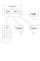
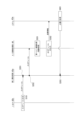
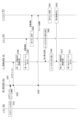
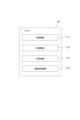
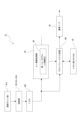
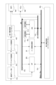
- FIG. 1 is a diagram illustrating a configuration example of an information processing system.
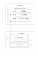
- FIG. 2 is a diagram for explaining each device that registers and downloads an AI model and an AI application via a marketplace function provided in a cloud-side information processing device.
- FIG. 2 is a diagram illustrating an example of the flow of processing executed by each device when registering or downloading an AI model or an AI application via a marketplace function.
- FIG. 2 is a diagram illustrating an example of the flow of processing executed by each device when deploying an AI application or an AI model.
- FIG. 2 is a diagram for explaining a connection mode between a cloud-side information processing device and an edge-side information processing device.
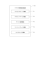
- FIG. 2 is a functional block diagram of a cloud-side information processing device.
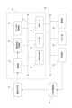
- FIG. 2 is a block diagram showing an example of the internal configuration of a camera.
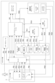
- FIG. 2 is a diagram showing a configuration example of an image sensor.
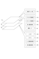
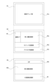
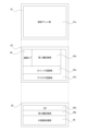
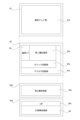
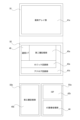
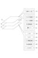
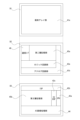
- FIG. 3 is a functional block diagram of a CPU included in the image sensor. It is a floor map showing a configuration example of each layer of an image sensor. It is a floor map which shows the other first example of a structure about each layer of an image sensor. It is a floor map which shows the second other example of a structure about each layer of an image sensor. It is a floor map which shows the other third example of a structure about each layer of an image sensor. It is a floor map which shows the modification of the third example of composition about each layer of an image sensor.
- FIG. 3 is a diagram showing a first example of execution timing of each process. It is a figure which shows the second example about the execution timing of each process. It is a figure which shows the third example about the execution timing of each process. It is another example of the functional block diagram of the CPU included in the image sensor.
- 1 is a diagram illustrating a first configuration example of a functional configuration of an image sensor that performs privacy mask processing;
- FIG. 3 is a diagram illustrating a second configuration example of a functional configuration of an image sensor that performs privacy mask processing.
- 7 is a flowchart illustrating processing executed by the image sensor regarding privacy mask processing.
- FIG. 1 is a diagram illustrating a first configuration example of a functional configuration of an image sensor that performs privacy mask processing
- FIG. 3 is a diagram illustrating a second configuration example of a functional configuration of an image sensor that performs privacy mask processing.
- 7 is a flowchart illustrating processing executed by the image sensor regarding privacy mask processing.
- FIG. 1 is a diagram illustrating
- FIG. 3 is a diagram illustrating a second configuration example of a functional configuration of an image sensor that performs privacy mask processing.
- FIG. 3 is a functional block diagram showing a modification of the configuration of the image sensor.
- FIG. 2 is a block diagram showing the software configuration of the camera.
- FIG. 2 is a block diagram showing an operating environment of a container when container technology is used.
- FIG. 2 is a block diagram showing an example of a hardware configuration of an information processing device. It is a figure explaining the flow of processing in other explanations. It is a figure which shows an example of the login screen for logging into a marketplace.
- FIG. 3 is a diagram illustrating an example of a developer screen presented to each developer using the marketplace.
- FIG. 3 is a diagram illustrating an example of a user screen presented to an application user who uses a marketplace.
- FIG. 1 is a block diagram showing a schematic configuration example of an information processing system 100 as an embodiment of the present technology.
- the information processing system 100 includes a cloud server 1, a user terminal 2, a plurality of cameras 3, a fog server 4, and a management server 5.
- the cloud server 1, user terminal 2, fog server 4, and management server 5 are configured to be able to communicate with each other via a network 6, such as the Internet.
- the cloud server 1, user terminal 2, fog server 4, and management server 5 are information processing devices equipped with a microcomputer having a CPU (Central Processing Unit), ROM (Read Only Memory), and RAM (Random Access Memory). It is configured.
- CPU Central Processing Unit
- ROM Read Only Memory
- RAM Random Access Memory
- the user terminal 2 is an information processing device that is assumed to be used by a user who is a recipient of a service using the information processing system 100.
- the management server 5 is an information processing device that is assumed to be used by a service provider.
- Each camera 3 is equipped with an image sensor such as a CCD (Charge Coupled Device) type image sensor or a CMOS (Complementary Metal Oxide Semiconductor) type image sensor, and captures an image of a subject and outputs image data (captured image data) as digital data. obtain.
- the sensors included in the camera 3 include, for example, an RGB sensor that captures an RGB image, a distance measurement sensor that outputs a distance image, and the like.
- each camera 3 also has a function of performing processing (for example, image recognition processing, subject detection processing, etc.) using AI (Artificial Intelligence) on the captured image.
- Each camera 3 is configured to be capable of data communication with the fog server 4, and is configured to transmit various data such as processing result information indicating the results of AI image processing etc. to the fog server 4, and receive various data from the fog server 4. It is said that it is possible to
- Each camera 3 may be used as a variety of surveillance cameras.
- surveillance cameras for indoor areas such as stores, offices, and residences
- surveillance cameras for monitoring outdoor areas such as parking lots and streets (including traffic surveillance cameras, etc.)
- Applications include surveillance cameras on production lines, surveillance cameras that monitor inside and outside of cars, etc.
- a surveillance camera is used in a store
- a plurality of cameras 3 are placed at predetermined positions in the store, and the user can monitor customer demographics (gender, age group, etc.) and behavior (flow line) in the store. It is conceivable to make it possible to confirm the following. In that case, it would be possible to generate the above-mentioned analytical information such as information on the customer demographics of these customers, information on their flow lines in the store, and information on the congestion status at the checkout register (for example, waiting time at the checkout register). It will be done.
- each camera 3 is placed at each position near the road so that the user can recognize information such as the license plate number (vehicle number), car color, and car model of passing vehicles. In that case, it is conceivable to generate information such as the license plate number, car color, car model, etc. as the above-mentioned analysis information.
- the cameras should be placed so that they can monitor each parked vehicle, and monitor whether there are any suspicious persons acting suspiciously around each vehicle.
- the suspicious person it may be possible to notify the user of the presence of the suspicious person and the suspicious person's attributes (gender, age group), etc.
- the fog server 4 is arranged for each monitoring target, for example, in the above-mentioned store monitoring application, the fog server 4 is placed in the monitored store together with each camera 3.
- the cloud server 1 does not need to directly receive the transmitted data from the multiple cameras 3 in the monitored target, which reduces the processing burden on the cloud server 1. It will be done.
- the fog server 4 is not limited to providing one for each monitoring target, but it is also possible to provide one fog server 4 for a plurality of monitoring targets.
- the fog server 4 function can be provided in the information processing system 100.
- the server 4 may be omitted, each camera 3 may be directly connected to the network 6, and the cloud server 1 may directly receive transmission data from a plurality of cameras 3.
- the cloud-side information processing device includes the cloud server 1 and the management server 5, and is a group of devices that provide services that are expected to be used by a plurality of users.
- the camera 3 and the fog server 4 correspond to the edge-side information processing device, and can be considered as a group of devices placed in an environment prepared by a user who uses a cloud service.
- both the cloud-side information processing device and the edge-side information processing device may be in an environment prepared by the same user.
- fog server 4 may be an on-premises server.
- the camera 3 which is an information processing device on the edge side, performs AI image processing
- the cloud server 1 which is an information processing device on the cloud side, processes the results of the AI image processing on the edge side. It is intended to realize advanced application functions using information (for example, result information of image recognition processing using AI).
- various methods can be considered for registering application functions in the cloud server 1 (or including the fog server 4), which is an information processing device on the cloud side.
- An example thereof will be explained with reference to FIG. 2.
- the fog server 4 is not shown in FIG. 2, the configuration may include the fog server 4. In this case, the fog server 4 may take on part of the functions on the edge side.
- the cloud server 1 and management server 5 described above are information processing devices that constitute a cloud-side environment. Further, the camera 3 is an information processing device that constitutes an environment on the edge side.
- the image sensor IS can be regarded as an information processing device that constitutes the edge-side environment. That is, it may be considered that the image sensor IS, which is another edge-side information processing device, is mounted inside the camera 3, which is the edge-side information processing device.
- the user terminals 2 used by users who use various services provided by the information processing device on the cloud side include an application developer terminal 2A used by a user who develops an application used for AI image processing, and an application developer terminal 2A used by a user who develops an application used for AI image processing.
- an application user terminal 2B used by a user and an AI model developer terminal 2C used by a user who develops an AI model used for AI image processing.
- the application developer terminal 2A may be used by a user who develops an application that does not use AI image processing.
- the information processing device on the cloud side is equipped with a training dataset for performing AI learning and an AI model that serves as the basis for development.
- a user who develops an AI model communicates with the information processing device on the cloud side using the AI model developer terminal 2C, and downloads these learning datasets and AI models.
- the training data set may be provided for a fee.
- an AI model developer registers personal information in a marketplace (electronic market) prepared as a function on the cloud side, making it possible to purchase various functions and materials registered in the marketplace. You may also purchase a training dataset.
- the AI model developer After developing an AI model using the learning dataset, the AI model developer registers the developed AI model in the marketplace using the AI model developer terminal 2C. Thereby, an incentive may be paid to the AI model developer when the AI model is downloaded.
- a user who develops an application downloads an AI model from the marketplace using the application developer terminal 2A, and develops an application (hereinafter referred to as "AI application") using the AI model.
- AI application an application
- an incentive may be paid to the AI model developer.
- the application development user registers the developed AI application in the marketplace using the application developer terminal 2A. Thereby, an incentive may be paid to the user who developed the AI application when the AI application is downloaded.
- a user who uses an AI application uses the application user terminal 2B to perform operations to deploy an AI application and an AI model from the marketplace to the camera 3, which is an edge-side information processing device that the user manages. conduct. At this time, an incentive may be paid to the AI model developer.
- This makes it possible for the camera 3 to perform AI image processing using an AI application and AI model, making it possible not only to capture images but also to detect customers and vehicles through AI image processing. .
- the deployment of the AI application and AI model means that at least a part of the program as the AI application can be deployed so that the target (device) as the execution entity can use the AI application and AI model.
- This refers to the installation of an AI application or AI model on a target as an execution entity so that it can be executed.
- the camera 3 may be configured to be able to extract the attribute information of the customer from the captured image captured by the camera 3 through AI image processing. These attribute information are transmitted from the camera 3 via the network 6 to the information processing device on the cloud side.
- a cloud application is deployed on the information processing device on the cloud side, and each user can use the cloud application via the network 6.
- the cloud applications there are applications that analyze the flow of customers visiting the store using their attribute information and captured images.
- Such cloud applications are uploaded by application development users and the like.
- a cloud application for flow line analysis using the application user terminal 2B
- application users can analyze the flow line of customers visiting their store and view the analysis results. has been done. Browsing of the analysis results may be performed by graphically presenting the flow lines of customers visiting the store on a map of the store.
- the results of the flow line analysis may be displayed in the form of a heat map, and the analysis results may be viewed by presenting the density of customers visiting the store. Further, the information may be displayed in categories according to attribute information of customers visiting the store.
- AI models optimized for each user may be registered. For example, captured images captured by a camera 3 placed in a store managed by a certain user are appropriately uploaded to an information processing device on the cloud side and stored therein.
- the AI model is re-learned, and the AI model is updated and re-registered in the marketplace.
- the AI model relearning process may be made available to the user as an option on the marketplace, for example.
- the recognition rate of image processing for images taken in a dark place, etc. can be improved.
- the recognition rate of image processing for images captured in bright places can be improved.
- the application user can always obtain optimized processing result information by deploying the updated AI model to the camera 3 again. Note that the AI model relearning process will be described later.
- AI models optimized for each camera may be registered.
- an AI model that is applied to the camera 3 that can acquire RGB images an AI model that is applied to the camera 3 that is equipped with a distance measurement sensor that generates a distance image, etc. can be considered.
- the AI model that should be used by camera 3 during bright hours is an AI model trained using vehicles and images captured in a bright environment
- the AI model that should be used by camera 3 during dark hours is an AI model that is trained using images taken in a dark environment.
- AI models trained using the images may be registered in respective marketplaces. It is desirable that these AI models be updated as appropriate to AI models with improved recognition rates through relearning processing.
- data with privacy-related information deleted from the perspective of privacy protection is uploaded.
- data with privacy-related information deleted may be made available to AI model development users and application development users.
- FIGS. 3 and 4 The flow of the above-described processing is shown in flowcharts in FIGS. 3 and 4. Note that the cloud-side information processing device corresponds to the cloud server 1, management server 5, etc. in FIG.
- the AI model developer uses the AI model developer terminal 2C, which has a display unit such as an LCD (Liquid Crystal Display) or an organic EL (Electro Luminescence) panel, to browse the list of datasets registered in the marketplace and display the desired data set.
- the AI model developer terminal 2C transmits a download request for the selected data set to the cloud-side information processing device in step S21.
- the cloud-side information processing device receives the request in step S1, and performs a process of transmitting the requested data set to the AI model developer terminal 2C in step S2.
- the AI model developer terminal 2C performs a process of receiving the data set in step S22. This allows the AI model developer to develop an AI model using the dataset.
- the AI model developer After the AI model developer finishes developing the AI model, the AI model developer performs operations to register the developed AI model in the marketplace (for example, the name of the AI model and the location where the AI model is placed).
- the AI model developer terminal 2C sends a request to register the AI model to the marketplace to the cloud-side information processing device.
- the cloud-side information processing device receives the registration request in step S3, and performs a registration process for the AI model in step S4, thereby making it possible to display the AI model on the marketplace, for example. .
- This allows users other than AI model developers to download AI models from the marketplace.
- an application developer who wants to develop an AI application uses the application developer terminal 2A to view a list of AI models registered in the marketplace.
- the application developer terminal 2A in response to an operation by the application developer (for example, an operation to select one of the AI models on the marketplace), the application developer terminal 2A sends a download request for the selected AI model to the cloud side information. Send to processing device.
- the cloud-side information processing device receives the request in step S5, and transmits the AI model to the application developer terminal 2A in step S6.
- the application developer terminal 2A receives the AI model in step S32. This allows application developers to develop AI applications that use AI models developed by others.
- step S33 the application developer terminal 2A transmits an AI application registration request to the cloud-side information processing device.
- the cloud-side information processing device can display the AI application on the marketplace, for example, by accepting the registration request in step S7 and registering the AI application in step S8. This allows users other than application developers to select and download AI applications on the marketplace.
- FIG. 4 shows an example in which a user other than an application developer selects and downloads an AI application on the marketplace.
- the application user terminal 2B selects a purpose in step S41.
- purpose selection the selected purpose is transmitted to the cloud-side information processing device.
- the cloud-side information processing device selects an AI application according to the purpose in step S9, and selects an AI model in step S10.
- table data in which AI applications and AI models are associated with each other according to the purpose is stored in the cloud-side information processing device, and it is possible to select the AI application and AI model according to the purpose.
- step S11 the cloud-side information processing device performs processing to deploy the selected AI application and AI model.
- the AI application and AI model are transmitted to the camera 3.
- step S51 an AI application and AI model deployment process is performed in step S51. This makes it possible to perform AI image processing on the captured image captured by the camera 3.
- the camera 3 acquires an image by performing an imaging operation in step S52. Then, in step S53, the camera 3 performs AI image processing on the acquired image to obtain, for example, an image recognition result.
- step S54 the camera 3 performs a process of transmitting the captured image and the result information of the AI image processing.
- both the captured image and the AI image processing result information may be transmitted, or only one of them may be transmitted.
- the cloud-side information processing device that has received this information performs analysis processing in step S12. Through this analysis process, for example, flow line analysis of customers visiting the store, vehicle analysis process for traffic monitoring, etc. are performed.
- step S13 the cloud-side information processing device performs analysis result presentation processing. This processing is realized, for example, by the user using the cloud application described above.
- the application user terminal 2B Upon receiving the analysis result presentation process, the application user terminal 2B performs a process of displaying the analysis result on a monitor or the like in step S42.
- the user of the AI application can obtain an analysis result according to the purpose selected in step S41.
- the AI model may be updated to optimize the image captured by the camera 3 managed by the application user. For example, as the camera 3 repeatedly executes each process of steps S52, S53, and S54, the captured images received from the camera 3 and the result information of AI image processing are accumulated in the cloud-side information processing device.
- the cloud-side information processing device performs an AI model update process in step S14.
- This process is a process of relearning the AI model by giving new data to the AI model.
- step S15 the cloud-side information processing device performs processing to deploy the new updated AI model.
- the camera 3 executes a process of developing a new AI model in step S55.
- the updated AI application may be further expanded in the process of step S55.
- a service using the information processing system 100 is assumed in which a user as a customer can select the type of function regarding AI image processing of each camera 3.
- the selection of the function type can also be referred to as the above-mentioned purpose setting.
- an image recognition function and an image detection function may be selected, or a more detailed type may be selected so as to exhibit an image recognition function or an image detection function for a specific subject.
- a service provider sells a camera 3 and a fog server 4 that have an image recognition function using AI to a user, and has the user install the camera 3 and fog server 4 at a location to be monitored.
- the company will also develop a service that provides users with the above-mentioned analytical information.
- the camera 3 uses AI image processing to obtain analysis information that corresponds to the customer's desired purpose. It is possible to selectively set functions.
- AI image processing functions are activated to detect customers and identify their attributes in order to function as store surveillance cameras, and in the event of a disaster, they Switch to AI image processing function to understand which products remain on the shelves. At the time of this switching, it is conceivable to change the AI model so that appropriate recognition results can be obtained.
- the management server 5 has a function of selectively setting the AI image processing function of the camera 3.
- management server 5 may be provided in the cloud server 1 or the fog server 4.
- the information processing device on the cloud side is equipped with a relearning function, a device management function, and a marketplace function, which are functions that can be used via the Hub.
- the Hub performs secure and highly reliable communication with the edge-side information processing device. Thereby, various functions can be provided to the edge-side information processing device.
- the relearning function is a function that performs relearning and provides a newly optimized AI model, thereby providing an appropriate AI model based on new learning materials.
- the device management function is a function to manage the camera 3 as an edge-side information processing device, and provides functions such as management and monitoring of the AI model deployed in the camera 3, and problem detection and troubleshooting. be able to.
- the device management function is also a function to manage information about the camera 3 and fog server 4.
- Information on the camera 3 and fog server 4 includes information on the chip used as the arithmetic processing unit, memory capacity, storage capacity, CPU and memory usage rate, and information on the information installed in each device. This information includes software information such as the OS (Operating System).
- device management functionality protects secure access by authenticated users.
- the marketplace function is a function to register AI models developed by the above-mentioned AI model developers and AI applications developed by application developers, and a function to deploy these developed products to authorized edge-side information processing devices. etc.
- the marketplace function also provides functions related to payment of incentives according to the deployment of developed products.
- the camera 3 as an edge-side information processing device is equipped with an edge runtime, an AI application, an AI model, and an image sensor IS.
- the edge runtime functions as embedded software for managing applications deployed on the camera 3 and communicating with the cloud-side information processing device.
- the AI model is a development of the AI model registered in the marketplace in the cloud-side information processing device, and the camera 3 uses the captured image to generate information on the results of AI image processing according to the purpose. can be obtained.
- the cloud-side information processing device collectively refers to devices such as the cloud server 1 and the management server 5.
- the cloud-side information processing device has a license authorization function F1, an account service function F2, a device monitoring function F3, a marketplace function F4, and a camera service function F5.
- the license authorization function F1 is a function that performs various types of authentication-related processing. Specifically, in the license authorization function F1, processing related to device authentication of each camera 3 and processing related to authentication of each of the AI models, software, and firmware used in the cameras 3 are performed.
- the above-mentioned software means software necessary for appropriately realizing AI image processing in the camera 3.
- AI image processing based on captured images is performed appropriately and that the results of AI image processing are sent to the fog server 4 and cloud server 1 in an appropriate format, it is necessary to control the input data to the AI model. It is also required to appropriately process the output data of AI models.
- the above software includes peripheral processing necessary to appropriately realize AI image processing.
- Such software is software for realizing a desired function using an AI model, and corresponds to the above-mentioned AI application.
- the AI application is not limited to one that uses only one AI model, but may also be one that uses two or more AI models.
- image data as recognition result information image data, etc., hereinafter referred to as "recognition result information" obtained by an AI model that executes AI image processing using a captured image as an input tensor is used as an input tensor.
- recognition result information image data, etc., hereinafter referred to as "recognition result information”
- it is an AI application that performs predetermined image processing as second AI image processing on the input tensor for the first AI image processing using coordinate information as recognition result information of the first AI image processing. It's okay.
- the input tensor for each AI image process may be a RAW image, or may be an RGB image obtained by performing synchronization processing on the RAW image. The same applies to the following explanation.
- the license authorization function F1 for authentication of the camera 3, a process is performed in which a device ID (Identification) is issued for each camera 3 when the camera 3 is connected via the network 6. Furthermore, regarding the authentication of AI models and software, unique IDs (AI model IDs, software IDs) are issued for each AI model and AI application that has been applied for registration from the AI model developer terminal 2C or the software developer terminal 7. Processing takes place.
- the license authorization function F1 also provides various keys, certificates, etc. for secure communication between the camera 3, the AI model developer terminal 2C, the software developer terminal 7, and the cloud server 1. Processing for issuing the certificate to the manufacturer of the camera 3 (particularly the manufacturer of the image sensor IS to be described later), AI model developer, and software developer is performed, as well as processing for updating and suspending certification validity.
- the license authorization function F1 when user registration (registration of account information accompanied by issuance of a user ID) is performed by the account service function F2 described below, the camera 3 (device ID above) purchased by the user and A process of linking the information with the user ID is also performed.
- the account service function F2 is a function that generates and manages user account information.
- the account service function F2 receives input of user information and generates account information based on the input user information (generates account information including at least user ID and password information).
- the account service function F2 also performs registration processing (registration of account information) for AI model developers and AI application developers (hereinafter sometimes abbreviated as "software developers").
- the device monitoring function F3 is a function that performs processing for monitoring the usage status of the camera 3. For example, various factors related to the usage status of the camera 3 include the location where the camera 3 is used, the output frequency of output data of AI image processing, the free space of the CPU and memory used for AI image processing, etc. Monitor information such as usage rate.
- the marketplace function F4 is a function for selling AI models and AI applications. For example, a user can purchase an AI application and an AI model used by the AI application via a sales website (sales site) provided by the marketplace function F4. Additionally, software developers are allowed to purchase AI models for creating AI applications via the sales site mentioned above.
- the camera service function F5 is a function for providing services related to the use of the camera 3 to the user.
- This camera service function F5 is the function related to the generation of analysis information described above. That is, it is a function that generates analysis information of a subject based on processing result information of image processing in the camera 3 and performs processing for allowing the user to view it via the user terminal 2.
- the camera service function F5 includes an imaging setting search function.
- this imaging setting search function is a function of acquiring recognition result information of AI image processing from the camera 3 and searching for imaging setting information of the camera 3 using AI based on the acquired recognition result information.
- the imaging setting information broadly refers to setting information related to an imaging operation for obtaining a captured image.
- optical settings such as focus and aperture, settings related to the readout operation of captured image signals such as frame rate, exposure time, gain, etc., as well as gamma correction processing, noise reduction processing, super resolution processing, etc.
- the imaging settings of the camera 3 are optimized according to the purpose set by the user, and good inference results can be obtained.
- the camera service function F5 also includes an AI model search function.
- This AI model search function acquires recognition result information of AI image processing from camera 3, and uses AI to search for the optimal AI model to be used for AI image processing in camera 3 based on the acquired recognition result information. It is a function.
- the search for an AI model here refers to, for example, when AI image processing is realized using a CNN (Convolutional Neural Network) that includes convolution operations, various processing parameters such as weighting coefficients and setting information related to the neural network structure are used. (including, for example, kernel size information) etc.
- the camera service function F5 may include a function of determining processing assignment.
- processing allocation determination function when deploying an AI application to an edge-side information processing device, processing is performed to determine the deployment destination device for each SW component. Note that some SW components may be determined to be executed on the cloud-side device, and in this case, it is not necessary to perform the deployment process because they have already been deployed on the cloud-side device.
- imaging settings search function and AI model search function it is possible to perform imaging settings that will yield good results from AI image processing, and to select an appropriate AI model according to the actual usage environment.
- AI image processing can be performed using
- processing assignment determination function in addition to this, it is possible to ensure that AI image processing and its analysis processing are executed in an appropriate device.
- the camera service function F5 has an application setting function prior to deploying each SW component.
- the application setting function is a function to set an appropriate AI application according to the user's purpose.
- an appropriate AI application is selected depending on the purpose selected by the user.
- the SW components constituting the AI application are automatically determined.
- the combination of SW components may be different depending on whether the user's request is focused on privacy or speed.
- the user terminal 2 (corresponding to the application user terminal 2B in FIG. 2) accepts the user's operation to select the purpose (application), and selects an appropriate AI application according to the selected application. Processing etc. are performed.
- the cloud server 1 alone realizes the license authorization function F1, the account service function F2, the device monitoring function F3, the marketplace function F4, and the camera service function F5. It is also possible to adopt a configuration in which the information processing apparatuses share the burden of implementation. For example, it is conceivable that one information processing device performs each of the above functions. Alternatively, it is also possible that a single function among the above functions is shared and performed by a plurality of information processing apparatuses (for example, the cloud server 1 and the management server 5).
- an AI model developer terminal 2C is an information processing device used by an AI model developer.
- the software developer terminal 7 is an information processing device used by an AI application developer.
- FIG. 7 is a block diagram showing an example of the internal configuration of the camera 3.
- the camera 3 includes an imaging optical system 31, an optical system drive section 32, an image sensor IS, a control section 33, a memory section 34, and a communication section 35.
- the image sensor IS, the control section 33, the memory section 34, and the communication section 35 are connected via a bus 36, and are capable of mutual data communication.
- the imaging optical system 31 includes lenses such as a cover lens, zoom lens, and focus lens, and an aperture (iris) mechanism. This imaging optical system 31 guides light (incident light) from the subject and focuses it on the light receiving surface of the image sensor IS.
- the optical system drive unit 32 comprehensively represents the zoom lens, focus lens, and aperture mechanism drive units included in the imaging optical system 31.
- the optical system drive unit 32 includes actuators for driving each of the zoom lens, focus lens, and aperture mechanism, and a drive circuit for the actuators.
- the control unit 33 is configured with a microcomputer having, for example, a CPU, a ROM, and a RAM, and the CPU executes various processes according to programs stored in the ROM or programs loaded in the RAM, thereby controlling the camera. Performs overall control of step 3.
- a microcomputer having, for example, a CPU, a ROM, and a RAM, and the CPU executes various processes according to programs stored in the ROM or programs loaded in the RAM, thereby controlling the camera. Performs overall control of step 3.
- control unit 33 instructs the optical system drive unit 32 to drive the zoom lens, focus lens, aperture mechanism, etc.
- the optical system drive unit 32 moves the focus lens and zoom lens, opens and closes the aperture blades of the aperture mechanism, etc. in response to these drive instructions.
- the control unit 33 controls writing and reading of various data to and from the memory unit 34 .
- the memory unit 34 is a nonvolatile storage device such as an HDD (Hard Disk Drive) or a flash memory device, and is used as a storage destination (recording destination) for image data output from the image sensor IS.
- control unit 33 performs various data communications with external devices via the communication unit 35.
- the communication unit 35 in this example is configured to be able to perform data communication with at least the fog server 4 (or cloud server 1) shown in FIG.
- the image sensor IS is configured as, for example, a CCD type image sensor, a CMOS type image sensor, or the like.
- the image sensor IS includes an imaging section 41, an image signal processing section 42, an internal sensor control section 43, an AI image processing section 44, a memory section 45, and a communication I/F 46, each of which communicates data with each other via a bus 47. It is considered possible.
- the imaging section 41 includes a pixel array section in which pixels having photoelectric conversion elements such as photodiodes are arranged two-dimensionally, and a readout circuit that reads out electrical signals obtained by photoelectric conversion from each pixel of the pixel array section. It is possible to output the electrical signal as a captured image signal.
- the readout circuit performs, for example, CDS (Correlated Double Sampling) processing, AGC (Automatic Gain Control) processing, etc. on the electrical signal obtained by photoelectric conversion, and further performs A/D (Analog/Digital) conversion processing.
- CDS Correlated Double Sampling
- AGC Automatic Gain Control
- the image signal processing unit 42 performs preprocessing, synchronization processing, YC generation processing, resolution conversion processing, codec processing, etc. on the captured image signal as digital data after A/D conversion processing.
- preprocessing clamping processing for clamping the R, G, and B black levels to predetermined levels and correction processing between the R, G, and B color channels are performed on the captured image signal.
- simultaneous processing color separation processing is performed so that the image data for each pixel includes all R, G, and B color components. For example, in the case of an image sensor using a Bayer array color filter, demosaic processing is performed as color separation processing.
- a luminance (Y) signal and a color (C) signal are generated (separated) from R, G, and B image data.
- the resolution conversion process the resolution conversion process is performed on image data that has been subjected to various types of signal processing.
- the codec processing the image data that has been subjected to the various processes described above is subjected to encoding processing for recording or communication, and file generation, for example.
- video file formats such as MPEG-2 (MPEG: Moving Picture Experts Group) and H. It is possible to generate files in formats such as H.264.
- the image signal processing unit 42 calculates information about the subject based on two signals output from the image sensor IS as iToF (indirect time of flight), for example. The distance information is calculated and a distance image is output.
- iToF indirect time of flight
- the in-sensor control unit 43 instructs the imaging unit 41 to control the execution of the imaging operation.
- the image signal processing unit 42 also controls the execution of processing.
- the AI image processing unit 44 performs image recognition processing as AI image processing on the captured image.
- the AI image processing unit 44 is realized by a DSP (Digital Signal Processor).
- DSP Digital Signal Processor
- the image recognition functions that can be realized by the AI image processing unit 44 can be switched by changing the AI image processing algorithm. In other words, by switching the AI model used for AI image processing, the functional type of AI image processing can be switched.
- Various types of functions for AI image processing can be considered, and examples include the following types. ⁇ Class identification ⁇ Semantic segmentation ⁇ Person detection ⁇ Vehicle detection ⁇ Target tracking ⁇ OCR (Optical Character Recognition)
- class identification is a function that identifies the target class.
- the "class” here refers to information representing the category of an object, such as "person,”"car,””plane,””ship,””truck,””bird,””cat,””dog,””deer,””frog,”””Horse” etc.
- Target tracking is a function of tracking a subject that is a target, and can be translated as a function of obtaining historical information on the position of the subject.
- the switching of the AI model may be performed by an instruction from the cloud-side information processing device, or may be performed based on determination processing by the control unit 33 of the camera 3 or the in-sensor control unit 43. Furthermore, when switching the AI model, the AI model may be switched from a plurality of AI models stored in the memory unit 45, or may be switched by receiving and deploying the AI model from the cloud-side information processing device. Good too. By receiving an AI model from the cloud-side information processing device each time switching occurs, the capacity of the memory unit 45 can be suppressed, making it possible to achieve downsizing, power saving, and cost reduction.
- the memory unit 45 can be used as a so-called frame memory in which captured image data (RAW image data) obtained by the image signal processing unit 42 and image data after synchronization processing are stored.
- the memory unit 45 can also be used to temporarily store data used by the AI image processing unit 44 in the process of AI image processing.
- the memory unit 45 also stores information on AI applications and AI models used by the AI image processing unit 44.
- the information on the AI application and the AI model may be deployed in the memory unit 45 as a container using container technology, which will be described later, or may be deployed using microservice technology.
- By expanding the AI model used for AI image processing into the memory unit 45 it is possible to change the function type of AI image processing, or to change to an AI model whose performance has been improved through relearning.
- the explanation is based on examples of AI models and AI applications used for image recognition, but the invention is not limited to this, and programs executed using AI technology can also be used. etc. may be targeted.
- the capacity of the memory unit 45 is small, the information of the AI application or AI model is expanded into a memory outside the image sensor IS such as the memory unit 34 as a container using container technology, and then only the AI model is stored.
- the data may be stored in the memory unit 45 in the image sensor IS via the communication I/F 46 described below.
- the communication I/F 46 is an interface for communicating with the control unit 33, memory unit 34, etc. located outside the image sensor IS.
- the communication I/F 46 performs communication to acquire programs executed by the image signal processing unit 42 and AI applications and AI models used by the AI image processing unit 44 from the outside, and stores them in the memory unit 45 included in the image sensor IS. Make me remember. Thereby, the AI model is stored in a part of the memory section 45 included in the image sensor IS, and can be used by the AI image processing section 44.
- the AI image processing unit 44 performs predetermined image recognition processing using the AI application and AI model obtained in this way to recognize the subject according to the purpose.
- the recognition result information of the AI image processing is output to the outside of the image sensor IS via the communication I/F 46.
- the communication I/F 46 of the image sensor IS outputs not only the image data output from the image signal processing section 42 but also the recognition result information of the AI image processing. Note that it is also possible to output only either the image data or the recognition result information from the communication I/F 46 of the image sensor IS.
- captured image data used for the relearning function is uploaded from the image sensor IS to the cloud-side information processing device via the communication I/F 46 and the communication unit 35. Ru.
- recognition result information of AI image processing is output from the image sensor IS to another information processing device outside the camera 3 via the communication I/F 46 and the communication unit 35. .
- Image sensor configuration Various configurations of the image sensor IS described above are possible.
- the image sensor IS has a structure in which three layers are stacked.
- the image sensor IS is configured as a one-chip semiconductor device in which three layers of dies each serving as a semiconductor substrate are stacked.
- the image sensor IS includes a die D1 forming a first layer of a semiconductor substrate, a die D2 forming a second layer, and a die D3 forming a third layer.
- Each layer is electrically connected, for example, by a Cu--Cu bond.
- the image sensor IS includes an imaging section 41, an image signal processing section 42, an in-sensor control section 43, an AI image processing section 44, a memory section 45, and a communication I/F 46, which are classified by function as shown in FIG. However, each function may be completed in one layer by mounting electronic components on one layer, while others may have electronic components mounted over multiple layers.
- the imaging section 41 includes a pixel array section 41a provided on the die D1 and an analog circuit section 41b provided on the die D2 (see FIG. 8).
- the analog circuit section 41b includes a transistor as a readout circuit, a vertical drive circuit, a comparator, a circuit that performs CDS processing, AGC processing, etc., an A/D conversion section, and the like.
- the image signal processing section 42 includes a logic circuit section 42a provided on the die D2 and an ISP (Image Signal Processor) 42b provided on the die D3.
- ISP Image Signal Processor
- the logic circuit section 42a includes a circuit that performs processing to detect and correct defective pixels in the captured image signal as digital data generated by the A/D conversion section.
- the ISP 42b performs synchronization processing, YC generation processing, resolution conversion processing, codec processing, noise removal processing, etc. Note that some of the processing may be executed by the in-sensor control unit 43.
- the in-sensor control unit 43 is composed of a CPU 43a provided in the die D3, and functions as a control function F11, an authentication function F12, and an encryption function F13 shown in FIG. 9 by executing a predetermined program. Each function will be explained later.
- the AI image processing unit 44 is provided in the die D3 and functions as an inference processing unit.
- CV Computer Vision
- edge enhancement processing scaling processing
- affine transformation processing is performed.
- This can be performed by the CPU 43a or the like.
- the processing time can be reduced compared to when the CV processing is performed by the ISP 42b.
- these CV processes are, for example, processes for generating input images to an AI model. That is, these CV processes are processes for generating image data of a predetermined size defined as an input tensor of an AI model and suitable for AI image processing.
- CV processing does not need to be a process of generating an input image to an AI model, as long as it executes processing using a plurality of lines for each processing unit. For example, it may be a process of drawing (emphasizing) a bounding box in an area where a person is detected by AI image processing.
- the memory section 45 includes a second layer storage section 45a provided on the die D2 and a third layer storage section 45b provided on the die D3.
- the second layer storage unit 45a functions as a frame memory in which image data and RAW image data after being subjected to synchronization processing by the ISP 42b are stored. Note that even if the frame memory is provided not in the second layer but in the third layer or outside the image sensor IS, it is possible to obtain the effects described above or below.
- the third layer storage unit 45b functions as a working memory in which the process and results of AI image processing by the AI image processing unit 44 are stored. Further, the third layer storage unit 45b stores weighting coefficients, parameters, etc. for the AI model, and functions as a storage unit where the AI model is expanded.
- the third layer storage unit 45b and the AI image processing unit 44 in the same layer, it is possible to improve the transfer speed and readout speed of various intermediate data generated in the process of inference processing using the AI model. , it is possible to shorten the time required for inference processing.
- part of the data stored in the third layer storage section 45b can be stored in the second layer storage section 45a, and the third layer storage section 45b capacity can be reduced.
- the size of the third layer storage section 45b can be reduced, and the chip size of the semiconductor substrate forming the third layer can be reduced, and additional functions can be added to the third layer to improve the functionality of the image sensor IS. becomes possible.
- the second layer storage section 45a as a frame memory in the second layer, it is suitable when it is desired to perform a plurality of different processes on a frame image.
- a second layer storage section 45a as a frame memory in the second layer
- pixel values of part of the frame image stored in the frame memory can be rewritten for processing such as mask processing and addition of bounding boxes. This can be achieved by These processes can be realized by the CPU 43a, the memory controller, or their cooperation.
- the second layer storage section 45a and the third layer storage section 45b may include not only RAM but also ROM.
- the communication I/F 46 is provided in the die D2.
- the die D1 which is the first layer provided with the pixel array section 41a, as the outermost layer, light is easily incident on the pixel array section 41a, and the conversion efficiency of photoelectric conversion processing is improved.
- the pixel array section 41a is arranged in a second layer provided with an analog circuit section 41b that functions as a conversion processing section that performs A/D conversion on pixel signals read out from each pixel included in the pixel array section 41a.
- an analog circuit section 41b that functions as a conversion processing section that performs A/D conversion on pixel signals read out from each pixel included in the pixel array section 41a.
- the AI image processing section 44 It is possible to suppress the influence of electromagnetic noise generated during execution of the process on the charges accumulated in the pixel array section 41a.
- the analog circuit section 41b driven at a high voltage is not provided in the third layer, it is possible to employ cutting-edge semiconductor manufacturing processes in manufacturing the die D3 as a semiconductor substrate forming the third layer. It is possible to miniaturize the element.
- an image sensor IS has been known that has a two-layer structure, which includes a first layer in which the pixel array section 41a is mounted, and a second layer in which all other parts are mounted.
- the area of the second layer increases, causing the problem that the first layer becomes larger to match the size of the second layer. was there. In this case, an excess area was created on the first layer where no components were mounted, and it was difficult to say that it was appropriate in terms of board utilization efficiency.
- the overall size of the image sensor IS can be matched to the size of the pixel array section 41a, and the overall size of the image sensor IS can be reduced.
- control function F11 shown in FIG. 9 issues instructions to the imaging section 41 and the image signal processing section 42, and controls the imaging operation so that desired captured image data is obtained. Furthermore, the control function F11 instructs the AI image processing unit 44 to implement AI image processing using the AI model.
- the authentication function F12 sends a request to have the cloud-side information processing device authenticate that the image sensor IS has been registered using the certificate held in the image sensor IS, and the cloud-side information processing device Establish communication with the device.
- the encryption function F13 decrypts the developed AI model using the decryption key when the AI model is developed from outside the image sensor IS. Further, the encryption function F13 performs a process of encrypting image data output from the image sensor IS using an encryption key.
- the certificate handled by the authentication function F12 and the decryption key and encryption key handled by the encryption function F13 are stored in the ROM and RAM of the second layer storage section 45a and the third layer storage section 45b.
- FIG. 10 shows an example of the arrangement of the parts arranged on the dies D1, D2, and D3 forming each layer of the image sensor IS.
- a pixel array section 41a is formed over substantially the entire surface of the die D1 forming the first layer.
- the die D2 forming the second layer is provided with an analog circuit section 41b, a logic circuit section 42a, a second layer storage section 45a, and a communication I/F 46.
- the die D3 forming the third layer is provided with an ISP 42b, a CPU 43a, an AI image processing section 44, and a third layer storage section 45b.
- the third layer storage section 45b adjacent to the ISP 42b, CPU 43a, and AI image processing section 44, it is possible to speed up the processing in each section.
- the AI image processing executed by the AI image processing section 44 may handle a large amount of intermediate data, and so providing the third layer storage section 45b adjacently has a great effect.
- the chip size of each layer is the same.
- Image sensor IS in which the chip size of each layer is unified, can be manufactured using the so-called WoW (Wafer on Wafer) method, in which each layer is stacked on top of each other in a disk-shaped silicon wafer and then diced. The process can be completed in one go. Furthermore, since silicon wafers, which are large members, are stacked on top of each other, each chip can be easily positioned. Thereby, the difficulty level of the manufacturing process can be lowered and the process can be made smoother.
- WoW Wafer on Wafer
- each layer is stacked in the form of a wafer and cut out by one dicing process, it can be considered that the chip size of each layer is the same.
- the in-sensor control unit 43 (CPU 43a) is not provided in the third layer.
- the in-sensor control unit 43 (CPU 43a) is not provided in the third layer.
- mask processing that fills in people in images to protect privacy, processing that adds bounding boxes to indicate the type of subject detected by AI image processing, etc. are performed as frame memory. This can be achieved by directly manipulating the pixel values of the frame images stored in the second layer storage section 45a, but since this process can be achieved by a memory controller or the like, the CPU 43a does not need to be provided.
- FIG. 1 Another second configuration example is shown in FIG.
- the chip size of the die D3 constituting the third layer is smaller than the chip size of the dies D1 and D2 constituting the first and second layers.
- the length of the short side of the chip shape is shortened.
- the number of dies D3 formed on one wafer is increased, and the cost of chips can be reduced.
- the chips of the third layer are stacked on the die D2 forming the second layer after dicing. Therefore, it is possible to stack only the dies D3 that are found to be non-defective by inspection, so that the yield of the image sensor IS can be improved.
- the third layer includes two dies D3a and D3b.
- the die D3a is provided with an ISP 42b and an AI image processing section 44
- the die D3b is provided with a third layer storage section 45b.
- the ISP 42b provided on the die D3b and the DSP as the AI image processing section 44 are manufactured using an advanced process of several nanometers, and the third layer storage section 45b provided on the die D3b is manufactured using a highly integrated DRAM (Dynamic Random Access Memory) can be manufactured using different manufacturing processes.
- the third layer storage section 45b which is a DRAM, highly integrated, it is possible to increase the storage capacity of the third layer storage section 45b or to reduce the size of the third layer storage section 45b.
- the third layer storage section 45b is downsized, it becomes possible to arrange chips for realizing other functions in the reduced space, and it is possible to improve the functionality of the image sensor IS. .
- the two dies D3a and D3b arranged in the third layer are arranged apart from each other in the direction in which the short sides of the stacked surfaces extend. Thereby, the number of wires between the die D3a and the die D3b can be increased, the data transfer speed between both chips can be improved, and the processing speed can be increased.
- the die D3a and the die D3b may be arranged apart from each other in the direction in which the long sides of the stacked surfaces extend.
- the influence of electromagnetic noise caused by data transfer through the interchip wiring becomes stronger in the stacking direction of the chips, as the pixel signal of the pixel where the interchip wiring and the readout circuit overlap in the stacking direction. Therefore, pixels affected by electromagnetic noise can be easily identified, so that the noise reduction method does not become complicated.
- FIG. 4 Another fourth configuration example is shown in FIG.
- the arrangement of each part of the third layer is different from the above-mentioned example. Specifically, the area of the area where the analog circuit section 41b provided on the die D2 and the AI image processing section 44 provided on the die D3 overlap when viewed from the stacking direction is reduced.
- a conversion processing section 48 that is provided as a part of the analog circuit section 41b and performs A/D conversion is arranged at a position that does not overlap with the AI image processing section 44 arranged in the third layer when viewed from the stacking direction. be done. Thereby, it is possible to reduce the possibility that electromagnetic noise generated during execution of AI image processing by the AI image processing unit 44 will affect the result of A/D conversion. Therefore, captured image data (RAW image data) with less noise can be generated as digital data after A/D conversion. Furthermore, since A/D conversion and inference processing can be performed simultaneously, it is also possible to perform complex AI image processing that requires a long processing time.
- the fifth configuration example includes a CVDSP 42c as the image signal processing section 42 in addition to a logic circuit section 42a and an ISP 42b.
- the CVDSP 42c is constituted by a DSP that performs CV processing, and is provided in the die D3 constituting the third layer as shown in FIG.
- the CVDSP 42c performs image processing on frame images stored in the second layer storage section 45a as a frame memory. I do. Therefore, the CVDSP 42c is suitable for processing such as edge enhancement processing, scaling processing, and affine transformation processing that requires calculation using pixel data of pixels on a line different from the pixel targeted for image processing.
- the CVDSP 42c is capable of executing these processes without converting the frame image back into line data, and it is possible to improve the processing speed. Further, the CVDSP 42c enables calculations that require parallel processing using a plurality of lines for each processing unit, such as image processing based on a histogram of the entire image surface.
- the CVDSP 42c is provided in the die D3 constituting the third layer.
- the CVDSP 42c and the AI image processing section 44 are arranged adjacent to the third layer storage section 45b.
- the CVDSP 42c and the AI image processing unit 44 are configured to easily access the third layer storage unit 45b, and can speed up processing.
- Example of AI image processing An example of AI image processing executed by the AI image processing unit 44 will be described. In the explanation up to this point, several configuration examples of the image sensor IS have been given, but in the following explanation, the fifth configuration example of the image sensor IS explained using FIGS. 16 and 17 will be based on AI image processing. A case in which this is executed will be explained.
- a first example of AI image processing is to perform mask processing on an image.
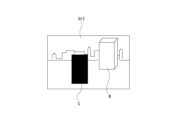
- FIG. 18 shows an example of the image Gr1 before mask processing.
- the image Gr1 before mask processing includes a person A as a subject and a box-shaped object B.
- the image Gr1 is input to the AI image processing unit 44 as an input tensor.
- the AI image processing unit 44 performs AI image processing to infer the region where the person A is imaged in the image Gr1 as an input tensor.
- the input tensor of the AI image processing unit 44 is a frame image
- the output tensor of the AI image processing unit 44 is an image in which an image area in which a person is imaged is filled in with a predetermined color as shown in FIG. It is what was done. That is, the AI image processing unit 44 performs masking of a predetermined area.
- the input tensor of the AI image processing unit 44 is a frame image
- the output tensor of the AI image processing unit 44 is coordinate information for specifying an image area where a person is imaged.
- the CPU 43a or the memory controller of the second layer storage section 45a assigns a predetermined pixel value (0, 255, etc.) to the image area specified by the coordinate information in the frame image stored in the second layer storage section 45a. Perform the overwriting process.
- a second example of AI image processing involves superimposing a bounding box on an image.
- the image Gr1 before superimposition is shown in FIG. 18 above.
- a person A and an object B are shown in the image Gr1.
- the image Gr1 is input to the AI image processing unit 44 as an input tensor.
- the AI image processing unit 44 detects a person A and an object B in the image Gr1, and gives a label indicating the classification result of the detected person A and object B.
- an image Gr3 (see FIG. 20) in which the frame image D as a bounding box is superimposed on the frame image is obtained.
- the image Gr3 on which the frame image D is superimposed is output as the output tensor of the AI image processing unit 44.
- Another method is to output coordinate information and label information of person A and object B as an output tensor from the AI image processing unit 44.
- the CPU 43a or the memory controller of the second layer storage section 45a overwrites a rectangle surrounding the image area specified by the coordinate information in the frame image stored in the second layer storage section 45a with predetermined pixel values. By doing so, the frame image D as a bounding box is superimposed.
- a frame image D may include a frame-shaped image and character information representing label information, or a frame image D may include only a frame-shaped image. . If the frame image D is only a frame-shaped image, the frame-shaped image may have a color according to the classification result of the subject.
- the AI image processing unit 44 switches and executes a plurality of AI image processes.
- the AI image processing unit 44 performs first AI image processing using the first AI model, then switches the AI model to the second AI model, and then performs the second AI image processing using the second AI model. Performs AI image processing.
- a frame image is used as an input tensor, and age information of a person captured in the image is estimated and output as an output tensor.
- a frame image is used as an input tensor, and gender information of a person captured in the image is estimated and output as an output tensor.
- CV processing by the CVDSP 42c is not performed between the first AI image processing and the second AI image processing.
- the fourth example of AI image processing is similar to the third example, in which a plurality of AI image processes are switched and executed. Furthermore, as a difference from the third example, CV processing by the CVDSP 42c is performed between both AI image processing.
- the image to be processed by the CVDSP 42c at this time is the frame image stored in the second layer storage section 45a.
- the AI image processing unit 44 performs a plurality of AI image processes using a plurality of AI models
- a first AI model specialized for the first AI image processing and a second AI model specialized for the second AI image processing are used.
- a second AI model can be used. Therefore, a highly accurate inference result can be obtained as a whole.
- switching of the AI model is performed by switching the weighting coefficient of the AI model.
- AI models can be switched with simple processing.
- the input tensor input to the second AI model is subjected to appropriate image processing by the CVDSP 42c, thereby making it possible to improve the recognition rate of AI image processing.
- the image processing by the CVDSP 42c is performed according to the recognition result of the first AI image processing, but the input tensor is data of a frame image stored in the second layer storage unit 45a as a frame memory. ing. That is, since the image sensor IS includes the second layer storage section 45a as a frame memory, it is possible to realize such processing.
- the process of detecting a specific object such as a person is performed in the first AI image processing, and the CVDSP 42c performs the process of cutting out a predetermined image area according to the result of the detection process, and the cut out partial image is
- the second AI image processing using the input tensor as the input tensor.
- face detection is performed in the first AI image processing
- processing to cut out the detected image area is performed in the CVDSP 42c
- processing to detect facial feature amounts is performed in the second AI image processing.
- the first AI image processing performs human body detection
- the CVDSP 42c performs processing to cut out the detected image area
- the second AI image processing performs skeletal estimation and posture estimation.
- the first AI image processing detects the license plate of the vehicle
- the CVDSP 42c performs processing to cut out the detected image area
- the second AI image processing performs processing to estimate the characters written on the license plate. This makes it possible to realize a function of identifying a vehicle that has passed in front of the traffic monitoring camera.
- the second AI image processing can estimate the attribute information about the person, the posture information and skeletal information of the person, and the character string about the license plate. This can be carried out suitably.
- a fifth example of AI image processing is one in which the AI image processing unit 44 switches between and executes a plurality of AI image processes. Further, the difference from the fourth example is that the image to be processed by the CV processing of the CVDSP 42c is not a frame image stored in the second layer storage unit 45a as a frame memory, but an output output from the first AI image processing. This is a point that is an image as a tensor.
- the CVDSP 42c performs further changes to the image changed by the first AI image processing.
- the AI image processing unit 44 performs denoising processing to remove noise from the frame image in the first AI image processing using the first AI model.
- the CVDSP 42c performs edge enhancement processing as CV processing on the noise-removed image that is the output tensor of the first AI model.
- the AI image processing unit 44 receives the edge-enhanced image as an input tensor for the second AI model, and performs detection processing such as person detection as second AI image processing.
- the CVDSP 42c can make the image as the input tensor input to the second AI image processing more appropriate by performing CV processing on the output tensor of the first AI image processing by the AI image processing unit 44. . Therefore, it becomes possible to infer the subject more accurately by the second AI image processing.
- the first AI image processing it is possible to apply various deterioration correction processes that correct image deterioration. Further, as the CV processing by the CVDSP 42c, various types of sharpening processing for sharpening the image can be applied.
- the deterioration correction process may include a dynamic range correction process in addition to the denoising process.
- the sharpening processing may include saturation correction processing and contrast correction processing.
- the second AI image processing is performed using the image obtained by performing the deterioration correction processing as the first AI image processing and further performing the sharpening processing by the CVDSP 42c as an input tensor, so that the second AI image In processing, it becomes possible to perform highly accurate inference processing.
- the process of inferring the image after sharpening may be performed in the first AI image processing, and the CV processing as deterioration correction processing may be performed in the CVDSP 42c.
- a first example of AI image processing is to perform mask processing on a partial area of an image (see FIGS. 18 and 19). Furthermore, a second example of AI image processing involves superimposing a bounding box on a partial area of an image (see FIGS. 18 and 20).
- FIG. 21 shows the flow of processing executed by each unit in the first and second examples of AI image processing.
- the ISP 42b generates an input tensor based on a frame image obtained by processing the analog circuit section 41b and the logic circuit section 42a on the pixel signal output from the pixel array section 41a.
- the frame image may be used as the input tensor as it is, or the frame image may be converted to match the format of the input tensor of the subsequent AI model.
- the generated input tensor is stored in the second layer storage section 45a in step S201.
- the AI image processing unit 44 acquires the input tensor from the second layer storage unit 45a in step S202.
- the input tensor is provided to the first AI model in step S301 to perform inference processing as first AI image processing.
- step S302 the AI image processing unit 44 outputs coordinate information as an output tensor of the first AI model to the CPU 43a.
- the coordinate information may be once stored in the memory section 45 and then output to the CPU 43a via the memory section 45.
- step S401 the CPU 43a performs overwriting processing according to the coordinate information.
- pixel values are overwritten in step S203 in the second layer storage section 45a. This realizes, for example, a process in which an image area in which a person is captured is replaced with a black image, or a process in which a bounding box is superimposed.
- a third example of AI image processing is one in which a plurality of AI image processes are switched and executed.
- FIG. 22 shows the flow of processing executed by each unit in the third example of AI image processing.
- the ISP 42b generates an input tensor based on a frame image obtained by processing the analog circuit section 41b and the logic circuit section 42a on the pixel signal output from the pixel array section 41a.
- the frame image may be used as the input tensor as it is, or the frame image may be converted to match the format of the input tensor of the subsequent AI model.
- the generated input tensor is stored in the second layer storage section 45a in step S201.
- the AI image processing unit 44 acquires the input tensor from the second layer storage unit 45a in step S202.
- the input tensor is provided to the first AI model in step S303 to perform inference processing as first AI image processing.
- the first AI image processing is, for example, processing for inferring the age of a person as a subject.
- step S304 the AI image processing unit 44 outputs the inference result (for example, estimated age information) as the first output tensor of the first AI model to the outside of the image sensor IS. Also, at this time, a completion notification of the inference process is sent to the CPU 43a.
- the inference result for example, estimated age information
- the CPU 43a Upon receiving the completion notification, the CPU 43a transmits an AI model switching instruction in step S402.
- the AI image processing unit 44 performs AI model switching in step S305. Thereby, the first AI model is switched to the second AI model.
- the AI image processing unit 44 acquires the input tensor from the second layer storage unit 45a again in step S204.
- This input tensor may be the same as the input tensor input to the first AI model.
- step S306 the AI image processing unit 44 executes second AI image processing using the second AI model.
- the second AI image processing is, for example, processing for inferring the gender of a person as a subject.
- step S307 the AI image processing unit 44 outputs the inference result (for example, estimated gender information) as a second output tensor of the second AI model to the outside of the image sensor IS.
- a completion notification may be sent to the CPU 43a.
- a fourth example of AI image processing is one in which a plurality of AI image processes are switched and executed. Furthermore, CV processing by the CVDSP 42c is performed between both AI image processing.
- FIG. 23 shows the flow of processing executed by each unit in the fourth example of AI image processing.
- the ISP 42b generates an input tensor based on a frame image obtained by processing the analog circuit section 41b and the logic circuit section 42a on the pixel signal output from the pixel array section 41a.
- the frame image may be used as the input tensor as it is, or the frame image may be converted to match the format of the input tensor of the subsequent AI model.
- the generated input tensor is stored in the second layer storage section 45a in step S201.
- the AI image processing unit 44 acquires the input tensor from the second layer storage unit 45a in step S202.
- the input tensor is provided to the first AI model in step S308 to perform inference processing as first AI image processing.
- the first AI image processing is, for example, processing for specifying an image area in which a person's face as a subject is captured.
- step S309 the AI image processing unit 44 outputs coordinate information as the first output tensor of the first AI model to the CPU 43a.
- the CPU 43a After receiving the coordinate information, the CPU 43a instructs the CVDSP 42c to cut out the data in step S403. At this time, the CPU 43a transmits the received coordinate information to the CVDSP 42c.
- the CVDSP 42c that has received the coordinate information acquires a frame image from the second layer storage unit 45a in step S205.
- step S501 the CVDSP 42c performs a process of cutting out the image area specified based on the coordinate information from the acquired frame image. As a result, the CVDSP 42c obtains a partial image including the person's face.
- step S502 the CVDSP 42c outputs the partial image to the AI image processing unit 44.
- the CPU 43a instructs the AI image processing unit 44 to switch the AI model in step S402, after instructing the cutting out or substantially at the same time as instructing the cutting out.
- the AI image processing unit 44 performs AI model switching in step S305.
- the AI image processing unit 44 performs second AI image processing in step S310 using the partial image received from the CVDSP 42c in step S502 as an input tensor.
- This process is a process of detecting feature amounts of a person's face included in a partial image.
- step S311 the AI image processing unit 44 outputs the detected feature quantity as a second output tensor to the outside of the image sensor IS.
- the AI image processing unit 44 switches between and executes a plurality of AI image processes. Further, the image to be processed by the CV processing of the CVDSP 42c is not a frame image stored in the second layer storage unit 45a as a frame memory, but an image as an output tensor output from the first AI image processing.
- FIG. 24 shows the flow of processing executed by each unit in the fifth example of AI image processing.
- the ISP 42b generates an input tensor based on a frame image obtained by processing the analog circuit section 41b and the logic circuit section 42a on the pixel signal output from the pixel array section 41a.
- the frame image may be used as the input tensor as it is, or the frame image may be converted to match the format of the input tensor of the subsequent AI model.
- the generated input tensor is stored in the second layer storage section 45a in step S201.
- the AI image processing unit 44 acquires the input tensor from the second layer storage unit 45a in step S202.
- the input tensor is provided to the first AI model in step S312 to perform inference processing as first AI image processing.
- the first AI image processing is, for example, denoising processing that removes noise from an image.
- step S313 the AI image processing unit 44 outputs the image data after noise removal as the first output tensor of the first AI model to the third layer storage unit 45b.
- the image data after noise removal is stored in the third layer storage unit 45b in step S601.
- the AI image processing unit 44 sends a completion notification of the denoising process to the CPU 43a.
- step S404 the CPU 43a that has received the completion notification instructs the CVDSP 42c to perform edge enhancement, which is an example of a process for sharpening an image.
- the CPU 43a transmits instruction information to the CVDSP 42c.
- the CVDSP 42c which has received the instruction information regarding edge enhancement, acquires the image data after noise removal from the third layer storage unit 45b in step S602.
- step S503 the CVDSP 42c performs image processing to emphasize edges on the acquired image data after noise removal. As a result, the CVDSP 42c obtains image data after edge emphasis.
- step S504 the CVDSP 42c transmits the edge-enhanced image data to the AI image processing unit 44. Note that when transmitting the edge-enhanced image data from the CVDSP 42c to the AI image processing unit 44, the image data may be temporarily stored in the third layer storage unit 45b.
- the CPU 43a instructs the AI image processing unit 44 to switch the AI model in step S402, after instructing edge emphasis or substantially at the same time as instructing edge emphasis.
- the AI image processing unit 44 performs AI model switching in step S305.
- the CPU 43a After the AI model switching process, the CPU 43a performs second AI image processing in step S314 using the edge-enhanced image data received from the CVDSP 42c in step S504 as an input tensor.
- This process is a process for detecting a person included in an image.
- step S315 the AI image processing unit 44 outputs information about the detected person as a second output tensor to the outside of the image sensor IS.
- FIG. 25 shows an example of the first execution timing.
- the first execution timing example is such that the execution period of the AI image processing by the AI image processing unit 44 does not overlap with the A/D conversion processing by the analog circuit unit 41b.
- the A/D conversion process and the AI image process are executed in a time-sharing manner during the frame period Tf during which one frame image is generated, thereby completing the process.
- processing such as development by the ISP 42b is performed almost simultaneously with A/D conversion. This generates an input tensor to the AI model.
- AI image processing is executed by the AI image processing unit 44, and after the completion of the AI image processing, the inference result is output as an output tensor from the AI model. Since the development process is completed after the A/D conversion process is completed, the AI image processing is necessarily executed after the A/D conversion process is completed.
- one AI image processing is performed using one AI model, so it is better to perform AI image processing between A/D conversion processing. It is easy to understand.
- FIG. 26 shows an example of the second execution timing.
- the timing of the A/D conversion process by the analog circuit section 41b and the development process by the ISP 42b is the same as the first example of execution timing.
- the processing timing by the AI image processing unit 44 is different from the first execution timing example.
- the total execution period of the A/D conversion processing by the analog circuit section 41b and the AI image processing by the AI image processing section 44 is set to be longer than the frame period Tf. That is, the AI image processing by the AI image processing unit 44 is performed so that the execution period partially overlaps with the A/D conversion processing.
- the processing time related to the AI image processing tends to be long. Therefore, when the amount of calculation is large, the execution periods of A/D conversion processing and AI image processing may have to partially overlap.
- the electromagnetic Image quality deterioration due to noise may be suppressed.
- FIG. 27 shows an example of the third execution timing. Similar to the first execution timing example, the execution period of the A/D conversion process by the analog circuit section 41b and the execution period of the AI image processing by the AI image processing section 44 are made not to overlap. Moreover, the execution period of the memory overwriting process by the CPU 43a and the image output process by the communication I/F 46, which are performed after the AI image processing, is made not to overlap with the A/D conversion process.
- Configuration for privacy protection In the above example, an example was described in which mask processing (hereinafter referred to as "privacy mask processing") is performed on an image area in which a person is imaged in order to protect privacy.
- mask processing hereinafter referred to as "privacy mask processing”
- an example of a configuration provided in the image sensor IS so as not to output an image for which privacy protection is not ensured outside the image sensor IS will be described.
- the CPU 43a serving as the in-sensor control unit 43 provided in the die D3 forming the third layer in the image sensor IS has a communication control function in addition to a control function F11, an authentication function F12, and an encryption function F13. It has F14.
- the communication control function F14 performs communication control when captured image data and metadata as inference results are transmitted from the camera 3 to other devices, for example by controlling an antenna provided outside the image sensor IS. I do.
- Communication with other devices realized by the communication control function F14 is, for example, LPWA (Low Power Wide Area) such as SIGFOX or LTE-M (Long Term Evolution Machine).
- LPWA Low Power Wide Area
- SIGFOX Small Integrated Circuit
- LTE-M Long Term Evolution Machine
- the image sensor IS transmits not only image data as an output tensor obtained as an inference result, but also image data as an input tensor input to the AI model to the outside of the image sensor IS or the camera 3. be. This is done for the purpose of checking the operation of the image sensor IS. That is, although it is conceivable that the image sensor IS transmits various image data to the outside, privacy is strongly protected by providing the AI image processing section 44 for performing privacy mask processing within the image sensor IS. becomes possible.
- FIG. 29 shows a first configuration example of the image sensor IS. Note that FIG. 29 shows only the portions related to privacy mask processing extracted from the various portions of the image sensor IS.
- the image sensor IS includes a pixel array section 41a, a circuit section 49, an ISP 42b, an AI image processing section 44, a memory section 45, and a communication I/F 46 as parts related to privacy mask processing.
- the pixel array section 41a has the same configuration as each of the above-mentioned examples, so a description thereof will be omitted.
- the circuit section 49 includes the above-mentioned analog circuit section 41b and logic circuit section 42a. However, the circuit section 49 may be configured to include only the analog circuit section 41b, or may be configured to include both the analog circuit section 41b and the logic circuit section 42a.
- the ISP 42b performs processing to generate image data as an input tensor for the AI model constructed in the AI image processing unit 44.
- the AI image processing unit 44 is capable of executing first AI image processing using the first AI model M1 and second AI image processing using the second AI model M2.
- the first AI image processing and the second AI image processing may be executed simultaneously, or may be executed in a time-sharing manner by switching the AI model.
- the AI image processing unit 44 performs first AI image processing as inference processing using the first AI model M1 and second AI image processing as privacy mask processing using the second AI model M2. considered to be executable.
- the first AI image processing may be a process of detecting a person, a process of detecting another subject, or a process of detecting a feature amount of a specific subject. Alternatively, it may be a process of character recognition, a process of correcting image deterioration, or a process of sharpening the image.
- the input tensor to the second AI model M2 that implements privacy mask processing is the input tensor of the first AI model M1. Furthermore, the output tensor from the second AI model M2 is image data that has been subjected to privacy mask processing. That is, in the second AI model M2, as the privacy masking process, both a process of specifying an image area in which a person is shown in an image and a process of masking the specified area are performed.
- the memory section 45 is configured to include a ROM and a RAM, but in this example, the ROM of the memory section 45 is excerpted and described.
- the ROM serving as the memory unit 45 stores weighting coefficients, parameters, etc. for functioning as the second AI model M2. That is, the various numerical values stored in the memory unit 45 for making the second AI model M2 function cannot be rewritten.
- a ROM in which various parameters regarding the second AI model M2 are stored is provided in the die D3 as the third layer in which the AI image processing unit 44 functioning as the second AI model M2 is provided. This is desirable. Thereby, it is possible to quickly switch to the second AI image processing using the second AI model M2.
- the communication I/F 46 is capable of outputting only privacy-protected image data to the outside of the image sensor IS by receiving the output tensor that has been subjected to privacy mask processing by the second AI model M2. .
- the image sensor IS has a configuration for outputting an image as an input tensor to the first AI model M1 from the communication I/F 46.
- Such a configuration is for evaluating and checking the operation of the first AI model M1 in the image sensor IS, and the user can check both the input tensor and output tensor for the first AI model M1, It is possible to judge whether the inference processing is functioning normally or not.
- the configuration of the image sensor IS shown in FIG. 29 can be said to be suitable as a configuration for debugging an AI model.
- the input tensor to the first AI model M1 is image data that has not been subjected to privacy mask processing, it is possible to appropriately perform inference processing and the like.
- FIG. 30 shows a second configuration example of the image sensor IS. Note that FIG. 30 shows only the portions related to privacy mask processing extracted from the various portions included in the image sensor IS.
- the image sensor IS includes a pixel array section 41a, a circuit section 49, an ISP 42b, an AI image processing section 44, a privacy mask processing section PM, a memory section 45, and a communication I/F 46 as parts related to privacy mask processing.
- the pixel array section 41a and the circuit section 49 are the same as those in configuration example 1, so their explanation will be omitted.
- the ISP 42b performs processing to generate image data as an input tensor for the first AI model M1 constructed in the AI image processing unit 44.
- the image data as the input tensor is also input to the privacy mask processing unit PM.
- the AI image processing unit 44 performs inference processing such as person detection using the first AI model M1, and outputs the inference result to the privacy mask processing unit PM as an output tensor.
- the privacy mask processing unit PM receives the image data as an input tensor from the ISP 42b to the first AI model M1 and the detection result as an output tensor from the first AI model M1, and processes the image area in which the detected person is captured. Perform privacy mask processing to mask.
- the privacy mask processing unit PM in this example performs privacy mask processing not by AI image processing using an AI model, but by processing by the CPU 43a or memory controller, for example. That is, for example, the privacy mask processing unit PM performs a process of overwriting the pixel values of a predetermined image area in the input tensor stored in the second layer storage unit 45a with a predetermined value.
- the memory section 45 shown in FIG. 30 includes only the ROM selected from the RAM and the ROM.
- the ROM stores a program executed by the privacy mask processing unit PM. Thereby, predetermined privacy mask processing can be reliably executed.
- FIG. 31 shows an example of the flow of processing executed by the privacy mask processing unit PM of this example.
- the privacy mask processing unit PM obtains the input tensor and output tensor for the first AI model M1 in step S701.
- step S702 the privacy mask processing unit PM determines whether a person class is included in the higher ranking of the inference results. If it is determined that the person class is included, the privacy mask processing unit PM performs privacy mask processing on the image area in which the subject to which the person class has been assigned is detected in step S703.
- privacy masking is to be performed when the person class is included at the top of the inference results, only subjects that are highly likely to be people are subjected to privacy masking. Furthermore, if privacy mask processing is to be performed when the person class is included in the top five of the inference results, subjects that are unlikely to be people are also subject to privacy mask processing. In this case, privacy is strongly protected.
- the privacy mask processing unit PM After performing the privacy mask processing, the privacy mask processing unit PM outputs the input tensor after the mask processing to the communication I/F 46 in step S704.
- the privacy mask processing unit PM outputs the image data as the acquired input tensor as it is to the communication I/F 46 in step S705. .
- FIG. 32 shows a third configuration example of the image sensor IS. Note that FIG. 32 shows only the parts related to privacy mask processing extracted from each part of the image sensor IS.
- the image sensor IS includes a pixel array section 41a, a circuit section 49, an ISP 42b, an AI image processing section 44, a memory section 45, and a communication I/F 46 as parts related to privacy mask processing.
- the pixel array section 41a and the circuit section 49 have the same configuration as in configuration example 1, so their description will be omitted.
- the ISP 42b includes an input tensor processing unit 41b1 that performs development processing and CV processing for input tensors, and a normal image processing unit 41b2 that performs CV processing and the like for normal images (for example, high-resolution images).
- the normal image is an image as a through image displayed on the display section of the camera 3, an image recorded in the memory section 45 for viewing, or the like.
- the input tensor processing unit 41b1 performs processing to generate image data as an input tensor for the AI model constructed in the AI image processing unit 44.
- the normal image processing unit 41b2 performs processing to generate image data for recording by performing the above-mentioned synchronization processing, YC generation processing, resolution conversion processing, codec processing, noise removal processing, etc.
- the AI image processing unit 44 is enabled to execute first AI image processing (inference processing) using the first AI model M1 and second AI image processing (privacy mask processing) using the second AI model M2.
- the input tensor generated by the input tensor processing unit 41b1 is input to the first AI model M1.
- the output tensor from the first AI model M1 is not shown because it can be output to each part.
- the input tensor of the first AI model M1 and the image data generated by the normal image processing unit 41b2 can be input as input tensors to the second AI model M2.
- the second AI model M2 performs a privacy mask process for each input tensor to identify and mask an image area in which a person appears.
- the output tensor from the second AI model M2 is supplied to the communication I/F 46 as privacy-protected image data and output to the outside of the image sensor IS.
- the memory section 45 shown in FIG. 32 includes only the ROM selected from the RAM and the ROM.
- the ROM stores various parameters such as weighting coefficients for the AI image processing unit 44 to function as the second AI model M2.
- the image sensor IS includes a pixel array section 41a, an analog circuit section 41b, a logic circuit section 42a, a second layer storage section 45a as a frame memory, an ISP 42b, an AI image processing section 44, a CPU 43a, and a third layer storage section as a working memory. 45b, a communication I/F 46a for MIPI ("MIPI" in the figure), and a communication I/F 46b for PCIe (Peripheral Component Interconnect Express) ("PCIe" in the figure).
- MIPI MIPI
- PCIe Peripheral Component Interconnect Express
- the authentication function F12 and the encryption function F13 are provided as functions of the CPU 43a, but in this modification, the authentication function F12 and the encryption function F13 are provided separately from the CPU 43a. There is.
- the authentication function F12 and the encryption function F13 appropriately execute the above-described authentication process, encryption process, and decryption process in response to instructions from the CPU 43a.
- the certificate used for the authentication process, the encryption key used for the encryption process, and the decryption key used for the decryption process may be stored in the third layer storage section 45b; It may be stored in a dedicated storage unit that can be used.
- This modified example includes a plurality of buses 47, unlike the example shown in FIG. Specifically, the first one is a memory bus 47a to which the ISP 42b, the AI image processing section 44, the CPU 43a, the third layer storage section 45b, and the MIPI communication I/F 46a are connected.
- the memory bus 47a is mainly used by the ISP 42b, the AI image processing unit 44, and the CPU 43a to access the third layer storage unit 45b as a working memory. Furthermore, the memory bus 47a is used to output MIPI standard image data to the outside of the image sensor IS.
- the second is an APB (Advanced Peripheral Bus) 47b as a low-speed bus to which the ISP 42b, the AI image processing unit 44, and the CPU 43a are connected.
- the APB 47b is mainly used to transmit commands from the CPU 43a to the ISP 42b and the AI image processing unit 44.
- the third is a high-speed AHB (Advanced High-Performance Bus) 47c to which the PCIe communication I/F 46b and the CPU 43a are connected.
- the AHB 47c is used when outputting label information as a recognition result.
- the communication I/F 46a for MIPI is an I/F used mainly for transmitting image data, specifically, frame images stored in the second layer storage section 45a as a frame memory, ISP 42b, etc. It serves as an I/F for outputting images that have been subjected to various processing by the AI image processing unit 44.
- the communication I/F 46b for PCIe is an I/F used mainly to send and receive information other than image data, and specifically, it is used when outputting label information etc. as a recognition result of inference processing. be done.
- the communication I/F 46b can also be used as an I/F to which a test image is input when the test image is used as an input tensor.
- AI image processing can be performed using not only an image obtained according to the light receiving operation of the pixel array section 41a but also an image input from outside the image sensor IS as a test image. Therefore, it is possible to verify the AI model.
- the communication I/F 46b for PCIe instead of the communication I/F 46a for MIPI, power consumption can be reduced.
- the communication I/F 46b for PCIe can be used when deploying an AI model (weighting coefficients and various parameters) within the image sensor IS. Further, in this case, the setting information of the ISP 42b may be expanded to the image sensor IS together with the AI model in order to make the input tensor to the AI model appropriate.
- the image sensor IS may include a CVDSP 42c. Furthermore, when the CVDSP 42c is provided, the setting information of the CVDSP 42c may be developed in the image sensor IS in accordance with the development of the AI model.
- the image sensor IS has a three-layer structure, but it may have a four-layer structure or more.
- a layer for cutting electromagnetic noise may be provided between the second layer and the third layer.
- the CV processing is performed after the AI image processing, and then the AI image processing is performed.
- CV processing may be performed after AI image processing, or AI image processing may be performed after CV processing.
- the first AI image processing is performed, the CV processing is performed on the result, and the second AI image processing is performed using the result of the CV processing as an input tensor. , it becomes possible to perform multiple AI image processes that require CV processing.
- AI image processing inference processing
- an operation system 51 is installed on various hardware 50 such as a CPU, GPU (Graphics Processing Unit), ROM, and RAM as the control unit 33 shown in FIG. 7 (see FIG. 34).
- various hardware 50 such as a CPU, GPU (Graphics Processing Unit), ROM, and RAM as the control unit 33 shown in FIG. 7 (see FIG. 34).
- the operation system 51 is basic software that performs overall control of the camera 3 in order to realize various functions in the camera 3.
- General-purpose middleware 52 is installed on the operation system 51.
- the general-purpose middleware 52 is software for realizing basic operations such as a communication function using the communication unit 35 as the hardware 50 and a display function using the display unit (monitor, etc.) as the hardware 50. be.
- the orchestration tool 53 and the container engine 54 deploy and execute the container 55 by constructing a cluster 56 as an operating environment for the container 55.
- the edge runtime shown in FIG. 5 corresponds to the orchestration tool 53 and container engine 54 shown in FIG. 34.
- the orchestration tool 53 has a function for causing the container engine 54 to appropriately allocate the resources of the hardware 50 and operation system 51 described above.
- the orchestration tool 53 groups the containers 55 into predetermined units (pods to be described later), and each pod is expanded to worker nodes (described later) in logically different areas.
- the container engine 54 is one of the middleware installed in the operation system 51, and is an engine that operates the container 55. Specifically, the container engine 54 has a function of allocating resources (memory, computing power, etc.) of the hardware 50 and the operation system 51 to the container 55 based on a configuration file included in middleware in the container 55.
- the resources allocated in this embodiment include not only resources such as the control unit 33 included in the camera 3 but also resources such as the in-sensor control unit 43, memory unit 45, and communication I/F 46 included in the image sensor IS. It will be done.
- the container 55 is configured to include middleware such as applications and libraries for realizing predetermined functions.
- the container 55 operates to implement a predetermined function using the resources of the hardware 50 and operation system 51 allocated by the container engine 54.
- the AI application and AI model shown in FIG. 5 correspond to one of the containers 55. That is, one of the various containers 55 deployed in the camera 3 realizes a predetermined AI image processing function using an AI application and an AI model.
- cluster 56 constructed by the container engine 54 and the orchestration tool 53 will be described with reference to FIG. 35.
- the cluster 56 may be constructed across a plurality of devices so that functions are realized using not only the hardware 50 of one camera 3 but also other hardware resources of other devices.
- the orchestration tool 53 manages the execution environment of the container 55 on a per worker node 57 basis. Further, the orchestration tool 53 constructs a master node 58 that manages all of the worker nodes 57 .
- the pod 59 is configured to include one or more containers 55, and implements a predetermined function.
- the pod 59 is a management unit for managing the container 55 by the orchestration tool 53.
- the operation of the pod 59 on the worker node 57 is controlled by the pod management library 60.
- the pod management library 60 includes a container runtime for allowing the pods 59 to use logically allocated resources of the hardware 50, an agent that receives control from the master node 58, communication between the pods 59, and communication with the master node 58. It is configured with a network proxy etc. That is, each pod 59 is enabled to implement a predetermined function using each resource by the pod management library 60.
- the master node 58 shares data with an application server 61 that deploys the pod 59, a manager 62 that manages the deployment status of the container 55 by the application server 61, and a scheduler 63 that determines the worker node 57 where the container 55 is placed. It is configured to include a data sharing section 64.
- the AI model may be stored in the memory unit 45 within the image sensor IS via the communication I/F 46 in FIG. 7, and AI image processing may be executed within the image sensor IS.
- the configuration shown in FIGS. 34 and 35 may be deployed in the memory unit 45 and in-sensor control unit 43 within the image sensor IS, and the above-described AI application and AI model may be executed using container technology within the image sensor IS.
- the container technology can be used even when deploying an AI application and/or an AI model to the fog server 4 or the cloud-side information processing device.
- the information of the AI application and the AI model is developed as a container or the like in a memory such as the nonvolatile memory unit 74, storage unit 79, or RAM 73 in FIG. 36, which will be described later, and is executed.
- the information processing device includes a CPU 71.
- the CPU 71 functions as an arithmetic processing unit that performs the various processes described above, and executes programs stored in the ROM 72 or a nonvolatile memory unit 74 such as an EEP-ROM (Electrically Erasable Programmable Read-Only Memory), or the storage unit 79.
- Various processes are executed according to the programs loaded into the RAM 73 from the RAM 73.
- the RAM 73 also appropriately stores data necessary for the CPU 71 to execute various processes.
- the CPU 71 included in the information processing device as the cloud server 1 functions as a license authorization section, an account service providing section, a device monitoring section, a marketplace function providing section, and a camera service providing section in order to realize the above-mentioned functions. .
- the CPU 71, ROM 72, RAM 73, and nonvolatile memory section 74 are interconnected via a bus 83.
- An input/output interface (I/F) 75 is also connected to this bus 83.
- the input/output interface 75 is connected to an input section 76 consisting of an operator or an operating device.
- an input section 76 consisting of an operator or an operating device.
- various operators and operating devices such as a keyboard, a mouse, a key, a dial, a touch panel, a touch pad, and a remote controller are assumed.
- a user's operation is detected by the input unit 76, and a signal corresponding to the input operation is interpreted by the CPU 71.
- a display section 77 consisting of an LCD or an organic EL panel, and an audio output section 78 consisting of a speaker etc. are connected to the input/output interface 75 either integrally or separately.
- the display unit 77 is a display unit that performs various displays, and is configured by, for example, a display device provided in the housing of the computer device, a separate display device connected to the computer device, or the like.
- the display unit 77 displays images for various image processing, moving images to be processed, etc. on the display screen based on instructions from the CPU 71. Further, the display unit 77 displays various operation menus, icons, messages, etc., ie, as a GUI (Graphical User Interface), based on instructions from the CPU 71.
- GUI Graphic User Interface
- the input/output interface 75 may be connected to a storage section 79 made up of a hard disk, solid-state memory, etc., and a communication section 80 made up of a modem or the like.
- the communication unit 80 performs communication processing via a transmission path such as the Internet, and communicates with various devices by wired/wireless communication, bus communication, etc.
- a drive 81 is also connected to the input/output interface 75 as necessary, and a removable storage medium 82 such as a magnetic disk, optical disk, magneto-optical disk, or semiconductor memory is appropriately installed.
- the drive 81 can read data files such as programs used for each process from the removable storage medium 82.
- the read data file is stored in the storage section 79, and images and sounds included in the data file are outputted on the display section 77 and the audio output section 78. Further, computer programs and the like read from the removable storage medium 82 are installed in the storage unit 79 as necessary.
- software for the processing of this embodiment can be installed via network communication by the communication unit 80 or the removable storage medium 82.
- the software may be stored in advance in the ROM 72, storage unit 79, or the like.
- the captured image captured by the camera 3 or the processing result of AI image processing may be received and stored in the removable storage medium 82 via the storage unit 79 or the drive 81.
- each of the cloud server 1, user terminal 2, fog server 4, and management server 5 is not limited to being composed of a single computer device as shown in FIG. 36, but may be composed of a system of multiple computer devices. may be done.
- the plurality of computer devices may be systemized using a LAN (Local Area Network) or the like, or may be placed at a remote location via a VPN (Virtual Private Network) using the Internet or the like.
- the plurality of computer devices may include computer devices as a server group (cloud) that can be used by a cloud computing service.
- edge-side AI model As mentioned above, after the SW component of the AI application and the AI model are deployed, the AI model is retrained and the AI model deployed to each camera 3 etc. is triggered by the operation of the service provider or user. (hereinafter referred to as "edge-side AI model") and the process flow when updating an AI application will be specifically described with reference to FIG. 24. Note that FIG. 37 is described focusing on one camera 3 among the plurality of cameras 3.
- the edge-side AI model to be updated is, as an example, the one deployed in the image sensor IS included in the camera 3.
- the edge-side AI model is the image sensor IS in the camera 3. It may also be something that is deployed outside.
- an AI model relearning instruction is given by the service provider or user.
- This instruction is performed using an API function provided in an API (Application Programming Interface) module provided in the cloud-side information processing device.
- API Application Programming Interface
- the amount of images for example, the number of images
- the amount of images used for learning will also be referred to as a "predetermined number of images.”
- the API module Upon receiving the instruction, the API module transmits a relearning request and image amount information to the Hub (similar to the one shown in FIG. 5) in processing step PS2.
- the Hub transmits an update notification and image amount information to the camera 3 as an edge-side information processing device.
- the camera 3 transmits the captured image data obtained by photographing to the image DB (Database) of the storage group in processing step PS4. This photographing process and transmission process are performed until a predetermined number of images required for relearning is achieved.
- the camera 3 when the camera 3 obtains an inference result by performing inference processing on the captured image data, it may store the inference result in the image DB as metadata of the captured image data in processing step PS4.
- the camera 3 After completing the shooting and transmission of the predetermined number of images, the camera 3 notifies the Hub in processing step PS5 that the transmission of the predetermined number of captured image data has been completed.
- the Hub Upon receiving the notification, the Hub notifies the orchestration tool that the preparation of data for relearning is complete in processing step PS6.
- the orchestration tool transmits an instruction to execute the labeling process to the labeling module.
- the labeling module acquires image data targeted for labeling processing from the image DB (processing step PS8), and performs labeling processing.
- the labeling process referred to here may be a process that performs class identification as described above, a process that estimates the gender or age of the subject of an image and assigns a label, or a process that assigns a label to the subject by estimating the gender or age of the subject. It may be a process of estimating the subject's behavior and assigning a label, or a process of estimating the behavior of the subject and assigning a label.
- the labeling process may be performed manually or automatically. Further, the labeling process may be completed by the information processing device on the cloud side, or may be realized by using a service provided by another server device.
- the labeling module After completing the labeling process, stores the labeling result information in the data set DB in processing step PS9.
- the information stored in the dataset DB may be a set of label information and image data, or may be image ID (Identification) information for identifying the image data instead of the image data itself. .
- the storage management unit that detects that the labeling result information is stored notifies the orchestration tool in processing step PS10.
- the orchestration tool that has received the notification confirms that the labeling process for the predetermined number of image data has been completed, and sends a relearning instruction to the relearning module in processing step PS11.
- the relearning module that has received the relearning instruction acquires a dataset to be used for learning from the dataset DB in processing step PS12, and acquires an AI model to be updated from the learned AI model DB in processing step PS13.
- the relearning module retrains the AI model using the acquired data set and AI model.
- the updated AI model obtained in this manner is stored again in the trained AI model DB in processing step PS14.
- the storage management unit that detects that the updated AI model has been stored notifies the orchestration tool in processing step PS15.
- the orchestration tool that has received the notification transmits an AI model conversion instruction to the conversion module in processing step PS16.
- the conversion module that has received the conversion instruction acquires the updated AI model from the learned AI model DB in processing step PS17, and performs the conversion process of the AI model.
- conversion is performed in accordance with the spec information of the camera 3, which is the destination device.
- downsizing is performed so as not to degrade the performance of the AI model as much as possible, and the file format is converted so that it can be operated on the camera 3.
- the AI model that has been converted by the conversion module is the edge-side AI model described above.
- This converted AI model is stored in the converted AI model DB in processing step PS18.
- the storage management unit that detects that the converted AI model has been stored notifies the orchestration tool in processing step PS19.
- the orchestration tool that has received the notification transmits a notification to the Hub to execute the update of the AI model in processing step PS20.
- This notification includes information for specifying the location where the AI model used for the update is stored.
- the Hub Upon receiving the notification, the Hub sends an AI model update instruction to the camera 3.
- the update instruction also includes information for specifying the location where the AI model is stored.
- the camera 3 performs a process of acquiring and developing the target converted AI model from the converted AI model DB. As a result, the AI model used by the image sensor IS of the camera 3 is updated.
- the camera 3 After completing the update of the AI model by developing the AI model, the camera 3 transmits an update completion notification to the Hub in processing step PS23.
- the Hub that has received the notification notifies the orchestration tool that the AI model update process for the camera 3 has been completed in processing step PS24.
- the AI model can be updated in the same way.
- the device (location) on which the AI model was deployed is stored in the storage management section on the cloud side, and the Hub stores the device (location) where the AI model is deployed from the storage management section.
- the device (location) is read and an AI model update instruction is sent to the device where the AI model has been deployed.
- the device that has received the update instruction performs a process of acquiring and developing the target converted AI model from the converted AI model DB. As a result, the AI model of the device that received the update instruction is updated.
- the orchestration tool transmits an instruction to download an AI application such as updated firmware to the deployment control module.
- the deployment control module transmits an AI application deployment instruction to the Hub.
- This instruction includes information to identify where the updated AI application is stored.
- the Hub transmits the expansion instruction to the camera 3 in processing step PS27.
- the camera 3 downloads and deploys the updated AI application from the container DB of the deployment control module.
- an AI application is defined by multiple SW components such as SW components B1, B2, B3, ... Bn, and an AI application is defined as an AI application.
- the location of each SW component is stored in the storage management unit on the cloud side, and when processing step PS27, the Hub stores the deployment location of each SW component from the storage management unit.
- the deployed device (location) is read out, and a deployment instruction is sent to the deployed device.
- the device that has received the deployment instruction downloads and deploys the updated SW component from the container DB of the deployment control module in processing step PS28.
- the AI application referred to here is a SW component other than the AI model.
- both the AI model and the AI application may be updated together as one container.
- the AI model and the AI application may be updated simultaneously rather than sequentially. This can be realized by executing each process of processing steps PS25, PS26, PS27, and PS28.
- the AI Models and AI applications can be updated.
- the AI model is retrained using captured image data captured in the user's usage environment. Therefore, it is possible to generate an edge-side AI model that can output highly accurate recognition results in the user's usage environment.
- each of the above-described processes may be executed not only when relearning the AI model but also when operating the system for the first time in the user's usage environment.
- FIG. 38 shows an example of the login screen G1.
- the login screen G1 is provided with an ID input field 91 for inputting a user ID and a password input field 92 for inputting a password.
- a login button 93 for logging in and a cancel button 94 for canceling the login are arranged below the password input field 92.
- operators such as an operator for transitioning to a page for users who have forgotten their password, an operator for transitioning to a page for new user registration, and the like.
- FIG. 39 is an example of a screen presented to, for example, an AI application developer using the application developer terminal 2A or an AI model developer using the AI model developer terminal 2C.
- purchasable learning datasets, AI models, AI applications, etc. are displayed on the left side.
- data are displayed on the left side.
- an input device such as a mouse to surround only the desired part of the image with a frame, Just enter your name and you're ready to learn. For example, if you want to perform AI learning with an image of a cat, you can surround only the cat part of the image with a frame and enter "cat" as the text input, and the image with the cat annotation will be used for AI learning. can be prepared for.
- an input field 95 is provided for registering learning datasets collected or created by the developer, and AI models and AI applications developed by the developer.
- An input field 95 is provided for each data item to input the name and data storage location. Furthermore, for the AI model, a check box 96 is provided for setting whether retraining is necessary or not.
- a price setting field (indicated as an input field 95 in the figure), etc. may be provided in which the price required when purchasing data to be registered can be set.
- the user name, last login date, etc. are displayed as part of the user information.
- the amount of currency, number of points, etc. that can be used by the user when purchasing data may be displayed.
- FIG. 40 shows, for example, a user who performs various analyzes (the above-mentioned application user) by deploying an AI application or an AI model to the camera 3 as an edge-side information processing device that the user manages. This is an example of a user screen G3.
- radio buttons 97 are arranged that allow selection of the type and performance of the image sensor IS installed in the camera 3, the performance of the camera 3, and the like.
- the user can purchase an information processing device as the fog server 4 via the marketplace. Therefore, radio buttons 97 for selecting each performance of the fog server 4 are arranged on the left side of the user screen G3. Further, a user who already has a fog server 4 can register the performance of the fog server 4 by inputting the performance information of the fog server 4 here.
- the user achieves the desired function by installing the purchased camera 3 (or the camera 3 purchased without going through the marketplace) at any location such as a store that the user manages.
- any location such as a store that the user manages.
- radio buttons 98 are arranged that allow selection of environmental information about the environment in which the camera 3 is installed. By appropriately selecting environmental information regarding the environment in which the camera 3 is installed, the user sets the above-mentioned optimal imaging settings for the target camera 3.
- An execution button 99 is provided on the user screen G3. By pressing the execution button 99, the screen changes to a confirmation screen for confirming the purchase and a confirmation screen for confirming the setting of environmental information. This allows the user to purchase the desired camera 3 and fog server 4, and to set environmental information regarding the camera 3.
- the image sensor IS includes a first layer (die D1) provided with a pixel array section 41a in which a plurality of pixels are arranged two-dimensionally, and a pixel array section 41a that is output from the pixel array section 41a.
- a conversion processing unit (analog circuit unit 41b) that performs A/D conversion to convert analog signals based on pixel signals into digital signals, and a second layer storage unit in which image data, which is digital data based on digital signals, is stored frame by frame. 45a, and a third layer (die D3) that includes an inference processing unit (AI image processing unit 44) that performs inference processing using image data as an input tensor.
- the second layer and the third layer can be made smaller compared to the case where the respective parts provided in the second layer and the third layer are combined into one layer. Therefore, the size of each layer can be made approximately the same as the size of the pixel array section 41a, and there is no need to create an extra area in which no components are mounted on the first layer, thereby reducing the size of the image sensor IS. I can do it. Furthermore, by providing a second layer storage unit 45a as a frame memory in the second layer, inference processing using frame images and other processing using frame images (for example, output processing of frame image data, etc.) are performed. This makes it possible to efficiently process cases. In addition, when the third layer storage section 45b is provided in the third layer, the storage capacity of the third layer storage section 45b can be reduced, and the size of the third layer storage section 45b and the size of the image sensor IS can be reduced. It becomes possible to perform conversion.
- the second layer (die D2) in the image sensor IS may be provided between the first layer (die D1) and the third layer (die D3).
- a conversion processing unit (analog circuit unit 41b) that performs A/D conversion on pixel signals read from pixels included in the pixel array unit 41a is provided in the second layer adjacent to the first layer. Processing up to A/D conversion can be performed smoothly.
- no other layer is disposed between the first layer and the second layer, wiring between layers can be facilitated, and the number of wiring members can be reduced.
- the pixel array unit 41a provided in the first layer is located away from the inference processing unit (AI image processing unit 44) provided in the third layer in the stacking direction, The influence of electromagnetic noise on charges is reduced, making it possible to reduce noise.
- the third layer (die D3) in the image sensor IS may be provided with the third layer storage section 45b serving as a working memory for inference processing.
- the inference process can be performed using the artificial intelligence model (AI model) stored in the third layer storage unit 45b provided in the same layer, thereby reducing the time required for the inference process. I can do it.
- AI model artificial intelligence model
- the conversion processing section (analog circuit section 41b) and inference processing section (AI image processing section 44) in the image sensor IS may be arranged at positions that do not overlap in the stacking direction of each layer. good. It is possible to reduce the possibility that electromagnetic noise generated during execution of inference processing by the inference processing unit will affect the result of A/D conversion. Therefore, image data with less noise (RAW image data) can be generated as digital data after A/D conversion. Furthermore, since A/D conversion and inference processing can be executed simultaneously, it is also possible to execute complex inference processing that requires a long processing time.
- the third layer (die D3) in the image sensor IS includes a processor (e.g., CPU) that is different from the processor (e.g., DSP) that functions as the inference processing unit (AI image processing unit 44).
- a processor e.g., CPU
- DSP digital signal processor
- AI image processing unit 44 the processor that functions as the inference processing unit 44.
- CV processing such as edge enhancement processing, scaling processing, and affine transformation processing can be performed using the CPU 43a with high processing power. Thereby, the processing time can be reduced compared to when the CV processing is performed by the ISP 42b.
- the third layer (die D3) of the image sensor IS is provided with an authentication processing unit (authentication function F12) that performs authentication processing regarding whether or not an artificial intelligence model used for inference processing can be deployed. It may be.
- the authentication processing unit performs, for example, a process for having the server device (cloud-side information processing device) authenticate that the image sensor IS is permitted to deploy an artificial intelligence model.
- the authentication processing unit manages necessary data such as certificates.
- the image sensor IS may receive the encrypted artificial intelligence model, but the authentication processing unit may receive the key to decrypt the encrypted artificial intelligence model. to manage.
- the authentication processing unit may manage keys for encrypting data to be output to the outside.
- Various data managed by the authentication processing unit are stored in storage units such as ROM and RAM provided in the second layer (die D2) and third layer (memory unit 45, second layer storage unit 45a, third layer storage unit 45b). is memorized. Thereby, only the artificial intelligence model received from the authorized server device can be deployed, and security can be improved. Furthermore, security can be improved for output data as well.
- the third layer (die D3) in the image sensor IS is provided with a communication control unit (communication control function F14) that performs communication control for outputting the results of inference processing to the outside. It may be.
- a communication control unit that controls an antenna provided outside the image sensor IS
- LPWA such as SIGFOX and LTE-M.
- the processing unit inside the image sensor IS (communication control unit) is It is possible to improve security by transmitting data by executing a program.
- the chip sizes of the first layer (die D1), second layer (die D2), and third layer (die D3) in the image sensor IS may be the same.
- the image sensor IS which has a unified chip size for each layer, can complete the dicing process only once by stacking each layer on the silicon wafer before dicing and then dicing. positioning is made easier. Thereby, the manufacturing process can be simplified. Note that "the same” as used herein can be considered to be the same when each layer is laminated in the state of a wafer and cut out by one dicing.
- the chip size of the third layer (die D3) in the image sensor IS is smaller than the chip size of the first layer (die D1) and the second layer (die D2). It's okay. Thereby, the cost of the third layer chip can be reduced.
- the third layer chips are pasted on one side of the second layer after dicing, only those chips that are found to be non-defective in the inspection after dicing can be used. Therefore, it is possible to improve the yield of the image sensor IS.
- a plurality of chips may be provided in the third layer (die D3) in the image sensor IS.
- the memory provided in the third layer (the third layer storage section 45b) is a highly integrated DRAM chip, and the chip that functions as a DSP or ISP is a chip manufactured using a cutting-edge process of 10 nm or smaller. be able to. That is, chips produced by different semiconductor manufacturing processes can be mixed in the same third layer. Therefore, the size can be made smaller than when these multiple chips are provided in different layers.
- the memory provided in the third layer a highly integrated chip, it is possible to reduce the size of the memory chip, and by providing a chip with a communication function in the space left open by such miniaturization, it can be multifunctional. becomes possible.
- each of the plurality of chips in the image sensor IS has a rectangular shape having a long side and a short side when viewed from above, and the plurality of chips are arranged with their long sides facing each other. It may be. For example, by arranging the long sides of a DRAM chip and a chip equipped with a DSP adjacent to each other, the number of wires between the processor and the memory can be increased, and processing speed can be increased.
- the A/D conversion in the second layer (die D2) and the inference process in the third layer (die D3) in the image sensor IS are designed so that their execution times do not overlap. may be done. Thereby, it is possible to eliminate the possibility that electromagnetic noise generated during execution of inference processing by the inference processing unit (AI image processing unit 44) will affect the result of A/D conversion.
- the image sensor IS includes a pixel array section 41a in which a plurality of pixels are arranged two-dimensionally, and a first artificial intelligence model ( Inference processing that executes a first inference process using a first AI model M1), and executes a second inference process using a second artificial intelligence model (second AI model M2) based on the result of the first inference process.
- AI image processing unit 44 For example, face detection is performed in the first inference process, and feature amount detection is performed in the second inference process. Alternatively, noise removal is performed in the first inference process, and feature quantity detection is performed in the second inference process.
- each An artificial intelligence model specialized for specific inference processing can be used, and overall highly accurate inference results can be obtained. Further, by performing multiple inference processes using multiple artificial intelligence models, it is possible to improve the functionality of the image sensor IS.
- the setting of the weighting coefficient for the artificial intelligence model is switched, so that the first artificial intelligence model (first AI model M1) and the first artificial intelligence model (first AI model M1) are switched. Switching between the two artificial intelligence models (second AI model M2) may be performed. This makes it possible to switch between artificial intelligence models with simple processing.
- the image sensor IS includes an image processing unit (CVDSP 42c) that performs image processing based on the result of the first inference process, and the inference processing unit (AI image processing unit 44) performs image processing by the image processing unit.
- the second inference process may be performed using the image subjected to this as an input tensor.
- the second inference process can be appropriately performed by the image processing unit performing image processing that improves the accuracy of the inference result of the second inference process.
- the image sensor IS includes a frame memory (second layer storage section 45a) that stores image data, and the image processing section (CVDSP 42c) performs the first inference on the image data stored in the frame memory.
- Image processing may be performed according to the inference result of the processing (first AI image processing). For example, in the first inference process, a process of detecting a predetermined subject from image data is performed.
- the image processing unit also performs processing to generate a partial image by cutting out an area where a predetermined subject is imaged from the image data (frame image) stored in the frame memory based on coordinate information about the detected subject. .
- the artificial intelligence model is switched and a process of extracting feature points of a predetermined subject from the cut out partial image is performed. Since the image sensor IS includes a frame memory, it is possible to perform image processing using image data before being subjected to the first inference process, that is, image data that is used as an input tensor in the first inference process.
- the first inference process is a process to detect a specific target object
- the second inference process is a process to detect a detected target object.
- the image processing unit (CVDSP 42c) performs image processing on the object detected by the first inference process from the image data stored in the frame memory (second layer storage unit 45a). It is also possible to perform processing to cut out an image area of .
- the detection target is a person's face, a person's body, a vehicle license plate, or the like.
- Processing to detect feature amounts includes, for example, feature amounts for a person's face as a detection target, feature amounts for detecting the skeleton and posture of a person's body as a detection target, and This is a process of detecting the numerical features of a license plate.
- the second inference process can suitably perform processes such as detecting attribute information about a person, posture information and skeletal information of a person, and character strings about a license plate using OCR.
- the inference processing unit (AI image processing unit 44) in the image sensor IS outputs image data as a result of the first inference processing (first AI image processing), and the image processing unit (CVDSP 42c) outputs image data as a result of the first inference processing (first AI image processing).
- Image processing may be performed on image data output from one inference process.
- image data obtained by removing noise from image data as a frame image is obtained as an inference result.
- the image processing unit performs image processing such as edge enhancement processing on the image data after noise removal.
- object recognition processing is performed using the image data from which noise has been removed and edges have been emphasized as an input tensor. This makes it possible to infer the subject more accurately.
- the first inference process is a process for correcting deterioration of image data as an input tensor
- the image processing unit (CVDSP 42c) performs the following as image processing: Processing may be performed to sharpen the corrected image data. Thereby, suitable image data from which feature quantities can be easily extracted can be input as the input tensor in the second artificial intelligence model.
- the image sensor IS includes a mask processing unit (AI image processing unit 44 or privacy mask processing unit) that performs mask processing (privacy mask processing) to mask a predetermined area in image data. PM) and a communication control unit (communication control function F14) that performs transmission control to transmit image data subjected to mask processing to other devices.
- a mask processing unit AI image processing unit 44 or privacy mask processing unit
- a communication control unit communication control function F14
- the predetermined area may be an area where a person is imaged.
- an image in which the person is masked is output from the image sensor IS, so that the privacy of the subject can be protected.
- the mask processing unit (AI image processing unit 44 or privacy mask processing unit PM) performs mask processing on the image data after the image processing, and the first artificial intelligence model
- the image data input to the second artificial intelligence model may be image data that has not been subjected to mask processing.
- the image sensor IS includes a frame memory (second layer storage section 45a) that stores image data, and a mask processing section (privacy mask processing section PM) that stores image data in the image data stored in the frame memory.
- Masking processing may be performed by changing the pixel value of a predetermined area to a predetermined value. Thereby, the masking process can be realized by changing part of the data stored in the frame memory, which requires less processing load.
- the mask processing unit (privacy mask processing unit PM) in the image sensor IS may perform mask processing (privacy mask processing) using an artificial intelligence model.
- the mask processing unit may use an artificial intelligence model that detects a person included in the image data and performs a process of masking the image area.
- the mask processing unit (privacy mask processing unit PM) in the image sensor IS uses the inference result of the first inference process or the inference result of the second inference process to mask Processing may be performed. For example, when a first inference process using an artificial intelligence model for detecting a person is executed in the image sensor IS, the mask processing unit executes a process of masking a part of the image area using the result of the inference process. It's okay. Thereby, efficient mask processing can be performed using the inference results. Note that when performing mask processing on the input image data of the first inference process, one artificial intelligence model that performs both the first inference process and the mask process may be used.
- the image sensor IS includes a ROM (memory unit 45) in which a program executed by the mask processing unit (privacy mask processing unit PM) is stored. You can leave it there. Thereby, it is possible to make it difficult to perform unauthorized processing such as unauthorized mask processing or avoidance of mask processing for protecting privacy. That is, it is possible to increase the possibility that appropriate mask processing will be reliably executed.
- ROM memory unit 45
- the information processing method includes a first inference process using a first artificial intelligence model based on image data output from a pixel array unit 41a in which a plurality of pixels are arranged two-dimensionally, and a first inference process.
- a computer device serving as an image sensor IS executes a second inference process using a second artificial intelligence model based on the result.
- the program according to the present technology is a program readable by a computer device, and causes the arithmetic processing unit of the image sensor IS to execute each process shown in FIGS. 22, 23, and 24.
- Such a program can be recorded in advance in an HDD (Hard Disk Drive) as a recording medium built into equipment such as a computer device, or in a ROM in a microcomputer having a CPU.
- the program may be a flexible disk, CD-ROM (Compact Disk Read Only Memory), MO (Magneto Optical) disk, DVD (Digital Versatile Disc), Blu-ray Disc (registered trademark), magnetic disk, semiconductor It can be stored (recorded) temporarily or permanently in a removable recording medium such as a memory or a memory card.
- a removable recording medium can be provided as so-called package software.
- it can also be downloaded from a download site via a network such as a LAN (Local Area Network) or the Internet.
- LAN Local Area Network
- the image sensor IS includes a pixel array section 41a in which a plurality of pixels are arranged two-dimensionally, and a frame memory (second frame memory) that stores image data output from the pixel array section 41a.
- a layer storage unit 45a an image processing unit (CVDSP 42c) that performs image processing on the image data stored in the frame memory, and an artificial intelligence model using the image data subjected to image processing by the image processing unit as an input tensor.
- an inference processing unit AI image processing unit 44
- image processing is not performed on input data for each line, but on input data that is image data including at least a plurality of lines of pixel data. Therefore, the image processing unit can perform processing on the entire input image. Compared to similar processing using ISP, which processes data line by line, when processing the entire input image as image data stored in frame memory, it is processed into line data. Since there is no need to do this, it is possible to speed up the processing and reduce the processing load.
- the image processing section (CVDSP 42c) and the inference processing section (AI image processing section 44) in the image sensor IS may be provided as different processors. Thereby, an appropriate processor can be applied according to the processing content of each of the image processing section and the inference processing section.
- the image processing unit (CVDSP 42c) in the image sensor IS may perform CV processing. Furthermore, in the image sensor IS, the CV processing may include at least a portion of edge enhancement processing, scaling processing, and affine transformation processing.
- the image processing unit (CVDSP 42c) performs such CV processing on the frame image, efficient processing can be performed. Specifically, when performing CV processing using the ISP, since the ISP processes each line data, it is necessary to convert the image data to line data and perform the CV processing. On the other hand, by configuring the image processing section with a DSP or the like, CV processing can be performed without converting the frame image into line data, so that processing efficiency can be improved.
- the image processing unit (CVDSP 42c) in the image sensor IS may generate the input tensor of the artificial intelligence model.
- image data and the like suitably corrected by the image processing unit are input to the artificial intelligence model as an input tensor. Therefore, highly accurate inference processing can be performed.
- the information processing method includes a process of storing image data output from a pixel array section 41a in which a plurality of pixels are arranged two-dimensionally, image processing on the stored image data, and image processing.
- a computer device executes inference processing using an artificial intelligence model using image data as an input tensor.
- the program in the present technology is a program readable by a computer device, and causes the arithmetic processing unit of the image sensor IS to execute each process shown in FIGS. 22, 23, and 24.
- the present technology can also adopt the following configuration.
- a first inference process using a first artificial intelligence model is executed based on the image data output from the pixel array section, and a second inference process is performed using a second artificial intelligence model based on the result of the first inference process.
- the first inference process is a process of detecting a specific object
- the second inference process is a process of detecting a feature amount of the detected object
- the image processing unit performs, as the image processing, a process of cutting out an image area of the object detected by the first inference process from the image data stored in the frame memory. sensor.
- the inference processing unit outputs image data as a result of the first inference processing, The image sensor according to (3) above, wherein the image processing unit performs image processing on the image data output from the first inference process.
- the first inference process is a process for correcting deterioration of image data as an input tensor,
- a mask processing unit that performs mask processing to mask a predetermined area in the image data;
- the predetermined area is an area where a person is imaged.
- an image processing unit that performs image processing on image data input to the first artificial intelligence model or the second artificial intelligence model;
- the mask processing unit performs the mask processing on the image data after the image processing,
- (11) comprising a frame memory for storing the image data;
- the mask processing unit performs the mask processing by changing pixel values in a predetermined area in the image data stored in the frame memory to a predetermined value.
- the image sensor described.
- (12) The image sensor according to any one of (8) to (11) above, wherein the mask processing unit performs the mask processing using an artificial intelligence model.
- a computer device executes a second inference process using a second artificial intelligence model based on the result of the first inference process.
- a program readable by a computer device a function of executing a first inference process using a first artificial intelligence model based on image data output from a pixel array unit in which a plurality of pixels are arranged two-dimensionally;
Landscapes
- Engineering & Computer Science (AREA)
- Multimedia (AREA)
- Physics & Mathematics (AREA)
- General Physics & Mathematics (AREA)
- Theoretical Computer Science (AREA)
- Software Systems (AREA)
- Health & Medical Sciences (AREA)
- General Health & Medical Sciences (AREA)
- Vascular Medicine (AREA)
- Signal Processing (AREA)
- Image Processing (AREA)
- Transforming Light Signals Into Electric Signals (AREA)
Abstract
Description
これにより、人工知能モデルが展開されるイメージセンサにおいて高機能化を図ることができる。
<1.情報処理システムの全体構成>
<2.AIモデル及びAIアプリケーションの登録>
<3.システムの機能概要>
<4.撮像装置の構成>
<5.イメージセンサの構成>
<6.イメージセンサの構成についてのその他の例>
<7.AI画像処理の例>
<7-1.第1例>
<7-2.第2例>
<7-3.第3例>
<7-4.第4例>
<7-5.第5例>
<8.処理の流れ>
<8-1.第1例及び第2例>
<8-2.第3例>
<8-3.第4例>
<8-4.第5例>
<9.タイミングチャート>
<10.プライバシー保護のための構成>
<10-1.イメージセンサの構成例1>
<10-2.イメージセンサの構成例2>
<10-3.イメージセンサの構成例3>
<11.変形例>
<12.AIモデル及びAIアプリケーションの展開>
<13.情報処理装置のハードウェア構成>
<14.その他>
<15.マーケットプレイスの画面例>
<16.まとめ>
<16-1.まとめ1>
<16-2.まとめ2>
<16-3.まとめ3>
<17.本技術>
図1は、本技術に係る実施形態としての情報処理システム100の概略構成例を示したブロック図である。
図示のように情報処理システム100は、クラウドサーバ1と、ユーザ端末2と、複数のカメラ3と、フォグサーバ4と、管理サーバ5とを備えている。本例では、クラウドサーバ1、ユーザ端末2、フォグサーバ4、及び管理サーバ5は、例えばインターネット等とされたネットワーク6を介した相互通信を行うことが可能に構成されている。
カメラ3が備えるセンサは、例えば、RGB画像を撮像するRGBセンサや、距離画像を出力する測距センサなどである。
また、後述するように各カメラ3は、撮像画像についてAI(Artificial Intelligence:人工知能)を用いた処理(例えば、画像認識処理や被写体検出処理など)を行う機能も有している。以降の説明においては、画像認識処理や被写体検出処理など、画像に対して行われる各種の処理を単に「画像処理」と記載する。例えば、AI(或いはAIモデル)を用いた画像に対する各種の処理は「AI画像処理」と記載する。
各カメラ3は、フォグサーバ4とデータ通信可能に構成され、例えばAI画像処理などの結果を示す処理結果情報等の各種データをフォグサーバ4に送信したり、フォグサーバ4から各種データを受信したりすることが可能とされる。
或いは、交通監視カメラの用途であれば、各カメラ3を道路近傍の各位置に配置し、ユーザが通過車両についてのナンバー(車両番号)や車の色、車種等の情報を認識できるようにすることが考えられ、その場合、上記した分析情報としては、これらナンバーや車の色、車種等の情報を生成することが考えられる。
更に、街中や駐車場の空きスペースを監視して、ユーザに車を駐車できるスペースの場所を通知することも考えられる。
なお、クラウドサーバ1もしくは、各カメラ3側に処理能力があるなどの理由で、フォグサーバ4の機能をクラウドサーバ1もしくは各カメラ3側に持たせることができる場合は、情報処理システム100においてフォグサーバ4を省略し、各カメラ3を直接ネットワーク6に接続させて、複数のカメラ3からの送信データをクラウドサーバ1が直接受信するようにしてもよい。
クラウド側情報処理装置にはクラウドサーバ1や管理サーバ5が該当し、複数のユーザによる利用が想定されるサービスを提供する装置群である。
上述したように、情報処理システム100においては、エッジ側の情報処理装置であるカメラ3においてAI画像処理を行い、クラウド側の情報処理装置であるクラウドサーバ1において、エッジ側におけるAI画像処理の結果情報(例えばAIを用いた画像認識処理の結果情報)を用いて高度なアプリケーション機能を実現するものである。
その一例について、図2を参照して説明する。
なお、フォグサーバ4については図2における図示を省略しているが、フォグサーバ4を備えた構成とされてもよい。その際におけるフォグサーバ4は、エッジ側の機能の一部を負担してもよい。
また、カメラ3はエッジ側の環境を構成する情報処理装置である。
なお、もちろん、アプリケーション開発者端末2AはAI画像処理を用いないアプリケーションを開発するユーザによって使用されてもよい。
これにより、カメラ3においてAIアプリケーション及びAIモデルを用いたAI画像処理を行うことが可能となり、画像を撮像するだけでなくAI画像処理によって来店客の検出や車両の検出を行うことが可能となる。
これらの属性情報は、カメラ3からネットワーク6を介してクラウド側の情報処理装置に送信される。
また、動線分析の結果をヒートマップの形で表示され、来店客の密度などが提示されることにより解析結果の閲覧が行われてもよい。
また、それらの情報は、来店客の属性情報ごとに表示の仕分けがなされていてもよい。
なお、AIモデルの再学習処理は、例えば、マーケットプレイス上でユーザがオプションとして選べるようにしてもよい。
即ち、アプリケーション利用ユーザは、更新されたAIモデルを再度カメラ3に展開しなおすことにより、常に最適化された処理結果情報を得ることが可能となる。
なお、AIモデルの再学習処理については改めて後述する。
また、明るい時間帯にカメラ3で用いられるべきAIモデルとして明るい環境で車両や撮像した画像を用いて学習されたAIモデルと、暗い時間帯にカメラ3で用いられるべきAIモデルとして暗い環境で撮像した画像を用いて学習されたAIモデルが、それぞれマーケットプレイスにおいて登録されていてもよい。
そしてこれらのAIモデルは再学習処理によって認識率が高められたAIモデルに適宜更新されることが望ましい。
なお、クラウド側情報処理装置は、図1におけるクラウドサーバ1や管理サーバ5などが該当する。
例えば、カメラ3がステップS52、S53、S54の各処理を繰り返し実行することにより、クラウド側情報処理装置には、カメラ3から受信した撮像画像やAI画像処理の結果情報が蓄積されていく。
なお、AIアプリケーションについても更新されている場合には、ステップS55の処理において、更新されたAIアプリケーションを更に展開してもよい。
本実施形態では、情報処理システム100を用いたサービスとして、顧客としてのユーザが各カメラ3のAI画像処理についての機能の種別を選択することのできるサービスを想定している。機能の種別の選択とは、上述した目的の設定と換言することもできる。また、例えば、画像認識機能と画像検出機能などを選択してもよいし、特定の被写体についての画像認識機能や画像検出機能を発揮するように更に細かい種別を選択してもよい。
例えば、ビジネスモデルとして、サービス提供者は、AIによる画像認識機能を有したカメラ3やフォグサーバ4をユーザに販売し、それらカメラ3やフォグサーバ4を監視対象となる場所に設置させる。そして、上述したような分析情報をユーザに提供するサービスを展開する。
図示のようにクラウド側情報処理装置は、ライセンスオーソリ機能F1、アカウントサービス機能F2、デバイス監視機能F3、マーケットプレイス機能F4、及びカメラサービス機能F5を有する。
撮像画像に基づくAI画像処理が適切に行われ、AI画像処理の結果が適切な形式でフォグサーバ4やクラウドサーバ1に送信されるようにするためには、AIモデルへの入力データを制御したり、AIモデルの出力データを適切に処理したりすることが要求される。上記のソフトウェアは、AI画像処理を適切に実現させるために必要な周辺処理を含んだソフトウェアとなる。このようなソフトウェアは、AIモデルを利用して所望の機能を実現するためのソフトウェアであり、上述のAIアプリケーションに該当する。
或いは、第一のAI画像処理の認識結果情報としての座標情報を用いて、第一のAI画像処理に対する入力テンソルに対して第二のAI画像処理としての所定の画像処理を施すAIアプリケーションであってもよい。なお、各AI画像処理に対する入力テンソルは、RAW画像であってもよいし、RAW画像に同時化処理を施したRGB画像などであってもよい。以降の説明においても同様である。
また、AIモデルやソフトウェアの認証については、AIモデル開発者端末2Cやソフトウェア開発者端末7から登録申請されたAIモデル、AIアプリケーションについて、それぞれ固有のID(AIモデルID、ソフトウェアID)を発行する処理が行われる。
また、ライセンスオーソリ機能F1では、カメラ3やAIモデル開発者端末2C、ソフトウェア開発者端末7とクラウドサーバ1との間でセキュアな通信が行われるようにするための各種の鍵や証明書等をカメラ3の製造業者(特に後述するイメージセンサISの製造業者)やAIモデル開発者、ソフトウェア開発者に発行する処理が行われると共に、証明効力の更新や停止のための処理も行われる。
さらに、ライセンスオーソリ機能F1では、以下で説明するアカウントサービス機能F2によりユーザ登録(ユーザIDの発行を伴うアカウント情報の登録)が行われた場合に、ユーザが購入したカメラ3(上記デバイスID)とユーザIDとを紐付ける処理も行われる。
また、アカウントサービス機能F2では、AIモデル開発者やAIアプリケーションの開発者(以下「ソフトウェア開発者」と略称することもある)についての登録処理(アカウント情報の登録)も行われる。
このカメラサービス機能F5の一つとしては、例えば、前述した分析情報の生成に係る機能を挙げることができる。すなわち、カメラ3における画像処理の処理結果情報に基づき被写体の分析情報を生成しユーザ端末2を介してユーザに閲覧させるための処理を行う機能である。
撮像設定探索機能が適切に機能することにより、ユーザによって設定された目的に応じてカメラ3の撮像設定が最適化され、良好な推論結果を得ることができる。
そして、これに加えて処理分担決定機能を有することで、AI画像処理及びその解析処理が適切な装置において実行されるように図ることができる。
また、ソフトウェア開発者端末7は、AIアプリケーションの開発者が使用する情報処理装置である。
図7は、カメラ3の内部構成例を示したブロック図である。
図示のようにカメラ3は、撮像光学系31、光学系駆動部32、イメージセンサIS、制御部33、メモリ部34、通信部35を備えている。イメージセンサISと制御部33とメモリ部34と通信部35はバス36を介して接続され、相互にデータ通信を行うことが可能とされている。
メモリ部34は、例えばHDD(Hard Disk Drive)やフラッシュメモリ装置等の不揮発性の記憶デバイスとされ、イメージセンサISから出力された画像データの保存先(記録先)として用いられる。
前処理では、撮像画像信号に対してR、G、Bの黒レベルを所定のレベルにクランプするクランプ処理や、R、G、Bの色チャンネル間の補正処理等を行う。同時化処理では、各画素についての画像データが、R、G、B全ての色成分を有するようにする色分離処理を施す。例えば、ベイヤー配列のカラーフィルタを用いた撮像素子の場合は、色分離処理としてデモザイク処理が行われる。YC生成処理では、R、G、Bの画像データから、輝度(Y)信号及び色(C)信号を生成(分離)する。解像度変換処理では、各種の信号処理が施された画像データに対して、解像度変換処理を実行する。
コーデック処理では、上記の各種処理が施された画像データについて、例えば記録用や通信用の符号化処理、ファイル生成を行う。コーデック処理では、動画のファイル形式として、例えばMPEG-2(MPEG:Moving Picture Experts Group)やH.264などの形式によるファイル生成を行うことが可能とされる。また静止画ファイルとしてJPEG(Joint Photographic Experts Group)、TIFF(Tagged Image File Format)、GIF(Graphics Interchange Format)等の形式のファイル生成を行うことも考えられる。なお、イメージセンサISが測距センサとされている場合には、画像信号処理部42は、例えば、iToF(indirect Time of Flight)としてのイメージセンサISから出力される二つの信号に基づいて被写体についての距離情報を算出して距離画像を出力する。
・クラス識別
・セマンティックセグメンテーション
・人物検出
・車両検出
・ターゲットのトラッキング
・OCR(Optical Character Recognition:光学文字認識)
ターゲットのトラッキングとは、ターゲットとされた被写体の追尾を行う機能であり、該被写体の位置の履歴情報を得る機能と換言できるものである。
なお、AIアプリケーションやAIモデルの情報は、後述するコンテナ技術を用いて、コンテナなどとしてメモリ部45に展開されてもよいし、マイクロサービス技術を用いて展開されてもよい。AI画像処理に用いられるAIモデルをメモリ部45に展開することにより、AI画像処理の機能種別を変更したり、再学習によって性能の向上が図られたAIモデルに変更したりすることができる。
なお、上述のように本実施の形態においては画像認識に用いられるAIモデルやAIアプリケーションについての例に基づいた説明を行っているが、これに限定されず、AI技術を用いて実行されるプログラム等が対象とされていてもよい。
また、メモリ部45の容量が小さい場合には、AIアプリケーションやAIモデルの情報は、コンテナ技術を用いて、コンテナなどとしてメモリ部34などイメージセンサIS外のメモリに展開した後、AIモデルだけを下記で説明する通信I/F46を介してイメージセンサIS内のメモリ部45に格納させるようにしてもよい。
これにより、AIモデルがイメージセンサISが備えるメモリ部45の一部に記憶され、AI画像処理部44による利用が可能となる。
なお、イメージセンサISの通信I/F46からは、画像データと認識結果情報の何れか一方だけを出力させることもできる。
上述したイメージセンサISの構成は各種考えられる。本実施の形態においては、イメージセンサISが3層に積層された構造を備えている。
各層は、例えば、Cu-Cu接合により電気的に接続されている。
なお、これらのCV処理は、例えば、AIモデルへの入力画像を生成するための処理とされる。即ち、これらのCV処理は、AIモデルの入力テンソルとして規定されている所定サイズの画像データであって、AI画像処理に適した画像データを生成する処理とされる。
また、CV処理は、処理単位ごとに複数のラインを用いた処理を実行するものであれば、AIモデルへの入力画像を生成する処理でなくてもよい。
例えば、AI画像処理によって人物が検出された領域に対してバウンディングボックスを(強調して)描画する処理などであってもよい。
これらの処理は、CPU43aやメモリコントローラ、或いはそれらの協業によって実現可能である。
また、画素アレイ部41aが設けられた第一層とAI画像処理を実行するAI画像処理部44が設けられた第三層とが積層方向に離れて位置されているため、AI画像処理部44の処理実行中に発生する電磁ノイズの画素アレイ部41aに蓄積された電荷に対する影響を抑制することができる。
また、制御機能F11は、AIモデルを用いたAI画像処理を実現するためにAI画像処理部44に対する指示を行う。
また、暗号機能F13は、イメージセンサISから出力される画像データを暗号化鍵を用いて暗号化する処理を行う。
イメージセンサISの構成については各種考えられる。ここでは、上述したイメージセンサISの構成以外の例をその他の例として説明する。
例えば、ダイD3aにはISP42bとAI画像処理部44とが設けられ、ダイD3bには第三層記憶部45bが設けられている。
例えば、ダイD3bに設けられるISP42bやAI画像処理部44としてのDSPを数nmの先端プロセスで製造すると共に、ダイD3bに設けられる第三層記憶部45bを高集積とされたDRAM(Dynamic Random Access Memory)として異なる製造プロセスで製造することが可能となる。
DRAMとされた第三層記憶部45bが高集積とされることにより、第三層記憶部45bの記憶容量の増加或いは第三層記憶部45bの小型化を図ることが可能となる。そして、第三層記憶部45bを小型化した場合には、削減されたスペースに他の機能を実現するためのチップを配置することが可能となり、イメージセンサISの高機能化を図ることができる。
これにより、ダイD3aとダイD3b間の配線数を多くすることができ、両チップ間のデータ転送速度を向上させることができ、処理の高速化を図ることができる。
チップ間配線のデータ転送によって生じる電磁ノイズの影響は、チップの積層方向において、チップ間配線と読み出し回路が積層方向において重なる画素の画素信号ほど強くなる。
従って、電磁ノイズの影響を受ける画素が特定しやすくされるため、ノイズリダクションの方法が複雑化せずに済む。
これにより、AI画像処理部44によるAI画像処理の実行中に発生する電磁ノイズがA/D変換の結果に影響を及ぼす可能性を低減させることができる。従って、A/D変換後のデジタルデータとしてノイズの少ない撮像画像データ(RAW画像データ)を生成することができる。
また、これにより、A/D変換と推論処理を同時に実行させることができるため、処理時間の長い複雑なAI画像処理を実行することも可能となる。
従って、CVDSP42cは、エッジ強調処理やスケーリング処理やアフィン変換処理など、画像処理の対象とされた画素と異なるラインの画素の画素データを用いた演算が必要な処理に好適である。
これにより、CVDSP42cやAI画像処理部44は、第三層記憶部45bへアクセスしやすい構成とされており、処理の高速化を図ることができる。
AI画像処理部44によって実行されるAI画像処理の例について説明する。
なお、ここまでの説明においてイメージセンサISについての幾つかの構成例を挙げたが、以降の説明では図16及び図17を用いて説明したイメージセンサISの五つ目の構成例においてAI画像処理が実行される場合について説明する。
AI画像処理についての第1例は、画像にマスク処理を施すものである。
マスク処理前の画像Gr1の例を図18に示す。
一つは、AI画像処理部44の入力テンソルはフレーム画像とされ、AI画像処理部44の出力テンソルは図19に示すような人物が撮像された画像領域が所定の色で塗りつぶされた画像とされたものである。即ち、AI画像処理部44は、所定領域のマスクまでを行うものである。
AI画像処理についての第2例は、画像にバウンディングボックスを重畳させるものである。
重畳前の画像Gr1は先の図18に示すものである。画像Gr1には、人物Aと物体Bが写っている。
もう一つの方法は、人物Aと物体Bの座標情報とラベル情報がAI画像処理部44の出力テンソルとして出力されるものである。この場合には、CPU43aや第二層記憶部45aのメモリコントローラが第二層記憶部45aに記憶されたフレーム画像において当該座標情報によって特定される画像領域を囲む矩形状に所定の画素値で上書きすることでバウンディングボックスとしての枠画像Dの重畳を行うものである。
AI画像処理についての第3例及び後述する第4例は、AI画像処理部44が複数のAI画像処理を切り替えて実行するものである。
このとき、第一AI画像処理と第二AI画像処理の間にCVDSP42cによるCV処理は行われない。
AI画像処理についての第4例は、第3例と同様に複数のAI画像処理を切り替えて実行するものである。また、第3例との相違点として、両AI画像処理の間にCVDSP42cによるCV処理が行われる。
なお、このときCVDSP42cの処理対象の画像は、第二層記憶部45aに記憶されたフレーム画像である。
即ち、イメージセンサISがフレームメモリとしての第二層記憶部45aを備えていることによりこのような処理を実現することが可能となる。
AI画像処理についての第5例は、AI画像処理部44が複数のAI画像処理を切り替えて実行するものである。また、第4例との相違点は、CVDSP42cのCV処理の処理対象の画像がフレームメモリとしての第二層記憶部45aに記憶されたフレーム画像ではなく、第一AI画像処理から出力された出力テンソルとしての画像とされた点である。
CVDSP42cは、第一AIモデルの出力テンソルとされたノイズ除去後の画像に対して、CV処理としてのエッジ強調処理を行う。
また、鮮明化処理としては、エッジ強調処理の他に彩度補正処理やコントラスト補正処理を挙げることができる。
もちろん、上述の逆として、第一AI画像処理において鮮明化後の画像を推論する処理を行い、CVDSP42cにおいて劣化補正処理としてのCV処理を実行してもよい。
上述したAI画像処理の第1例から第5例の各例について、各部が実行する処理の流れを説明する。
AI画像処理の第1例は、画像の一部領域にマスク処理を施すものである(図18及び図19参照)。また、AI画像処理の第2例は、画像の一部領域にバウンディングボックスを重畳させるものである(図18及び図20参照)。AI画像処理の第1例及び第2例において各部が実行する処理の流れについて図21に示す。
AI画像処理の第3例は、複数のAI画像処理を切り替えて実行するものである。AI画像処理の第3例において各部が実行する処理の流れについて図22に示す。
AI画像処理の第4例は、複数のAI画像処理を切り替えて実行するものである。また、両AI画像処理の間にCVDSP42cによるCV処理が行われる。AI画像処理の第4例において各部が実行する処理の流れについて図23に示す。
AI画像処理の第5例は、AI画像処理部44が複数のAI画像処理を切り替えて実行するものである。また、CVDSP42cのCV処理の処理対象の画像がフレームメモリとしての第二層記憶部45aに記憶されたフレーム画像ではなく、第一AI画像処理から出力された出力テンソルとしての画像とされている。AI画像処理の第5例において各部が実行する処理の流れについて図24に示す。
上述した各例を実現するにあたって各部における各処理の実行タイミングを説明する。
一つ目の実行タイミングの例について図25に示す。
上述した例では、プライバシーを保護するために人物が撮像された画像領域に対するマスク処理(以降、「プライバシーマスク処理」と記載)を行う例について説明した。
ここでは、イメージセンサIS外にプライバシーの保護が確保されていない画像を出力しないようにイメージセンサISが備える構成の例について説明する。
通信制御機能F14は、例えばイメージセンサISの外部に設けられたアンテナの制御を行うことにより、カメラ3から撮像画像データや推論結果としてのメタデータなどが他の機器に送信される際の通信制御を行う。
イメージセンサISの構成例1を図29に示す。なお、図29はイメージセンサISが備える各部のうちプライバシーマスク処理に関連する部分のみを抜粋して示したものである。
即ち、第二AIモデルM2においては、プライバシーマスク処理として、画像おける人物が写った画像領域を特定する処理と、当該特定された領域をマスクする処理の双方が行われる。
これにより、第二AIモデルM2を用いた第二AI画像処理への切り替えを迅速に行うことができる。
このような構成は、イメージセンサISにおいて第一AIモデルM1の評価や動作確認のためのものとされ、ユーザは、第一AIモデルM1についての入力テンソルと出力テンソルの双方を確認することにより、推論処理が正常に機能しているか否か等を判断することができる。
イメージセンサISの構成例2を図30に示す。なお、図30はイメージセンサISが備える各部のうちプライバシーマスク処理に関連する部分のみを抜粋して示したものである。
また、推論結果の上位5位に人物クラスが含まれている場合にプライバシーマスク処理を行うとした場合には、人物である可能性が低い被写体についてもプライバシーマスク処理の対象とされる。この場合にはプライバシーの保護が強固に図られる。
イメージセンサISの構成例3を図32に示す。なお、図32はイメージセンサISが備える各部のうちプライバシーマスク処理に関連する部分のみを抜粋して示したものである。
図7に示したイメージセンサISの構成の変形例について図33に示す。
イメージセンサISは、画素アレイ部41aとアナログ回路部41bとロジック回路部42aとフレームメモリとしての第二層記憶部45aとISP42bとAI画像処理部44とCPU43aとワーキングメモリとしての第三層記憶部45bとMIPI用の通信I/F46a(図中の「MIPI」)とPCIe(Peripheral Component Interconnect Express)用の通信I/F46b(図中の「PCIe」)とを備えている。
なお、認証処理に用いる証明書や暗号化処理に用いる暗号化鍵や復号処理に用いる復号鍵は、第三層記憶部45bに記憶されていてもよいが、認証機能F12や暗号機能F13がアクセス可能な専用の記憶部に記憶されていてもよい。
また、MIPI規格の画像データをイメージセンサISの外部に出力するためにメモリバス47aは利用される。
また、MIPI用の通信I/F46aの代わりにPCIe用の通信I/F46bを用いることにより、消費電力を抑えることが可能となる。
カメラ3にAIモデルやAIアプリケーション等を展開する方法は各種考えられる。一例としてコンテナ技術を用いた例を説明する。
なお、図5に示すエッジランタイムは図34に示すオーケストレーションツール53及びコンテナエンジン54に相当する。
コンテナ55は、コンテナエンジン54によって割り当てられたハードウェア50及びオペレーションシステム51のリソースを用いて所定の機能を実現するために動作する。
即ち、各ポッド59は、ポッド管理ライブラリ60によって各リソースを用いた所定の機能を実現可能とされる。
なお、前述したとおり、AIモデルについて、図7の通信I/F46を介してイメージセンサIS内のメモリ部45に格納させ、イメージセンサIS内でAI画像処理を実行させるようにしてもよいし、図34及び図35に示す構成をイメージセンサIS内のメモリ部45及びセンサ内制御部43に展開し、イメージセンサIS内でコンテナ技術を用いて前述したAIアプリケーション及びAIモデルを実行させてもよい。
また、後述するように、AIアプリケーション及び/またはAIモデルをフォグサーバ4やクラウド側情報処理装置に展開する場合でもコンテナ技術を用いることができる。
その際は、AIアプリケーションやAIモデルの情報は、コンテナなどとして、後述する図36の不揮発性メモリ部74、記憶部79またはRAM73などのメモリに展開されて実行される。
情報処理システム100が備えるクラウドサーバ1、ユーザ端末2、フォグサーバ4、管理サーバ5などの情報処理装置のハードウェア構成について図36を参照して説明する。
例えば入力部76としては、キーボード、マウス、キー、ダイヤル、タッチパネル、タッチパッド、リモートコントローラ等の各種の操作子や操作デバイスが想定される。
入力部76によりユーザの操作が検知され、入力された操作に応じた信号はCPU71によって解釈される。
表示部77は各種表示を行う表示部であり、例えばコンピュータ装置の筐体に設けられるディスプレイデバイスや、コンピュータ装置に接続される別体のディスプレイデバイス等により構成される。
また、カメラ3において撮像された撮像画像やAI画像処理による処理結果を受け取り、記憶部79やドライブ81を介してリムーバブル記憶媒体82に記憶させてもよい。
なお、クラウドサーバ1、ユーザ端末2、フォグサーバ4、管理サーバ5は、それぞれが図36のようなコンピュータ装置が単一で構成されることに限らず、複数のコンピュータ装置がシステム化されて構成されてもよい。複数のコンピュータ装置は、LAN(Local Area Network)等によりシステム化されていてもよいし、インターネット等を利用したVPN(Virtual Private Network)等により遠隔地に配置されたものでもよい。複数のコンピュータ装置には、クラウドコンピューティングサービスによって利用可能なサーバ群(クラウド)としてのコンピュータ装置が含まれてもよい。
上述のように、AIアプリケーションのSWコンポーネント及びAIモデルが展開された後、サービスの提供者や利用者(ユーザ)の操作をトリガとしてAIモデルの再学習と各カメラ3などに展開されたAIモデル(以降「エッジ側AIモデル」と記載)やAIアプリケーションの更新を行うときの処理の流れについて、具体的に、図24を参照して説明する。なお、図37は複数のカメラ3の中の1台のカメラ3に着目して記載したものである。また、以下の説明において更新対象とされたエッジ側AIモデルは、一例として、カメラ3が備えるイメージセンサISに展開されているものであるが、もちろん、エッジ側AIモデルはカメラ3におけるイメージセンサIS外に展開されているものでもよい。
該変換処理では、展開先の機器であるカメラ3のスペック情報等に合わせて変換する処理を行う。この処理では、AIモデルの性能をできるだけ落とさないようにダウンサイジングを行うと共に、カメラ3上で動作可能なようにファイル形式の変換などが行われる。
該通知を受信したHubは、処理ステップPS24でオーケストレーションツールに対してカメラ3のAIモデル更新処理が完了したことを通知する。
その場合には、AIモデルが展開された際に当該AIモデルが展開された装置(場所)をクラウド側のストレージ管理部などに記憶しておき、Hubは、ストレージ管理部からAIモデルが展開された装置(場所)を読み出し、AIモデルが展開された装置に対してAIモデルのアップデート指示を送信する。
アップデート指示を受けた装置は、処理ステップPS22において、変換済AIモデルDBから対象の変換済みAIモデルを取得して展開する処理を行う。これにより、アップデート指示を受けた装置のAIモデルの更新が行われる。
AIモデルに加えてAIモデルを利用するAIアプリケーションの更新を行う場合には、後述する処理が更に実行される。
また、ここでは説明の簡単のため、AIアプリケーションとして説明したが、前述の通り、AIアプリケーションはSWコンポーネントB1、B2、B3、・・・Bnなど複数のSWコンポーネントで定義されており、AIアプリケーションが展開された際に、各SWコンポーネントがどこに展開されたかをクラウド側のストレージ管理部などに記憶しておき、Hubは、処理ステップPS27を処理する際に、ストレージ管理部から各SWコンポーネントの展開された装置(場所)を読み出し、その展開された装置に対して、展開指示を送信するようにされている。展開指示を受けた装置は、処理ステップPS28において、展開制御モジュールのコンテナDBからアップデートされたSWコンポーネントをダウンロードして展開する。
なお、ここで言及するAIアプリケーションとは、AIモデル以外のSWコンポーネントである。
なお、上述した各処理は、AIモデルの再学習時だけでなく、ユーザの使用環境下においてシステムを初めて稼働させる際に実行してもよい。
マーケットプレイスに関してユーザに提示される画面の一例について、各図を参照して説明する。
ログイン画面G1には、ユーザIDを入力するためのID入力欄91と、パスワードを入力するためのパスワード入力欄92が設けられている。
なお、図示していないが、学習用データセットの購入の際に、学習用データセットの画像をディスプレイ上に表示させ、マウス等の入力装置を用いて画像の所望の部分のみを枠で囲み、名前を入力するだけで、学習の準備をすることができる。
例えば、猫の画像でAI学習を行いたい場合、画像上の猫の部分だけを枠で囲むと共に、テキスト入力として「猫」と入力することによって、猫のアノテーションが付加された画像をAI学習用に準備することができる。
また、所望のデータを見つけやすいように、「交通監視」、「動線分析」、「来店客カウント」のような目的を選択可能とされていてもよい。即ち、選択された目的に適合するデータのみが表示されるような表示処理がクラウドサーバ1及びユーザ端末2のそれぞれにおいて実行される。
また、既にフォグサーバ4を有しているユーザはフォグサーバ4の性能情報をここに入力することによって、フォグサーバ4の性能を登録することができる。
<16-1.まとめ1>
上述した各例において説明したように、イメージセンサISは、複数の画素が二次元に配列された画素アレイ部41aが設けられた第一層(ダイD1)と、画素アレイ部41aから出力される画素信号に基づくアナログ信号をデジタル信号に変換するA/D変換を行う変換処理部(アナログ回路部41b)とデジタル信号に基づくデジタルデータである画像データがフレームごとに記憶される第二層記憶部45aとが設けられた第二層(ダイD2)と、画像データを入力テンソルとした推論処理を行う推論処理部(AI画像処理部44)が設けられた第三層(ダイD3)と、を含む積層構造を有する。
これにより、第二層と第三層に設けられる各部を一つの層にまとめた場合と比較して第二層及び第三層を小さくすることができる。
従って、各層の大きさを画素アレイ部41aの大きさと略同じとすることができ、第一層に部品が搭載されていない余り領域を生じさせずに済み、イメージセンサISの小型化を図ることができる。
また、第二層にフレームメモリとしての第二層記憶部45aが設けられることで、フレーム画像を用いた推論処理とフレーム画像を用いた別の処理(例えばフレーム画像データの出力処理など)を行う場合に効率よく処理を行うことが可能となる。
また、第三層に第三層記憶部45bを設ける場合に、第三層記憶部45bの記憶容量を小さくすることができ、第三層記憶部45bの小型化延いてはイメージセンサISの小型化を行うことが可能となる。
これにより、第一層に設けられた画素アレイ部41aに光が入射されやすくなる。また、画素アレイ部41aが備える画素から読み出された画素信号に対してA/D変換を行う変換処理部(アナログ回路部41b)が第一層と隣接する第二層に設けられることで、A/D変換までの処理を円滑に行うことが可能となる。
更に、第一層と第二層の間に他の層が配置されないことで、層間の配線がしやすくされ、配線部材の削減を図ることができる。
また、第一層に設けられた画素アレイ部41aは第三層に設けられた推論処理部(AI画像処理部44)に対して積層方向に離れて位置されているため、画素に蓄積された電荷に対する電磁ノイズの影響が小さくされており、ノイズ低減を図ることができる。
これにより、推論処理は同じ層に設けられた第三層記憶部45bに記憶された人工知能モデル(AIモデル)を用いて推論処理を行うことができるため、推論処理に要する時間を短縮することができる。
推論処理部による推論処理の実行中に発生する電磁ノイズがA/D変換の結果に影響を及ぼす可能性を低減させることができる。従って、A/D変換後のデジタルデータとしてノイズの少ない画像データ(RAW画像データ)を生成することができる。
また、これにより、A/D変換と推論処理を同時に実行させることができるため、処理時間が大きくなる複雑な推論処理を実行することも可能となる。
例えば、処理能力の高いCPU43aを用いてエッジ強調処理やスケーリング処理やアフィン変換処理などのCV処理を行うことができる。これにより、ISP42bでCV処理を行うよりも処理時間を短縮することができる。
認証処理部は、例えば、人工知能モデルの展開が許可されたイメージセンサISであることをサーバ装置(クラウド側情報処理装置)に認証してもらうための処理を行う。そのために、認証処理部は証明書等の必要なデータを管理する。また、認証が許可された場合にはイメージセンサISは暗号化された人工知能モデルを受信することが考えられるが、認証処理部は、当該暗号化された人工知能モデルを復号するための鍵を管理する。更に、認証処理部は、外部に出力するデータを暗号化するための鍵を管理してもよい。
認証処理部が管理する各種データは第二層(ダイD2)や第三層に設けられたROMやRAMなどの記憶部(メモリ部45、第二層記憶部45a、第三層記憶部45b)に記憶される。
これにより、正規のサーバ装置から受信した人工知能モデルのみを展開することができセキュリティの向上を図ることができる。また、出力データについてもセキュリティの向上が図られる。
例えば、イメージセンサIS外に設けられたアンテナを制御する通信制御部が設けられることにより、SIGFOXやLTE-MなどのLPWAによる各種の通信を行うことが可能となる。
セキュアなデータをイメージセンサISから送信することを考えると、イメージセンサIS外の処理部がプログラムを実行することによってデータを送信する場合と比較してイメージセンサIS内の処理部(通信制御部)がプログラムを実行することによってデータを送信する方がセキュリティの向上を図ることが可能となる。
各層のチップサイズが統一されたイメージセンサISは、ダイシングする前のシリコンウエハの状態で各層を重ね合わせた後にダイシングを行うことにより、ダイシングの工程を1度で済ませることができ、更に、各チップの位置決めがしやすくされる。これにより、製造工程の簡易化を図ることができる。
なお、ここでいう「同一」とは、各層がウエハの状態で積層されて一度のダイシングで切り出された場合には、同一と見なすことができる。
これにより、第三層のチップのコストを削減することができる。また、第三層のチップはダイシングした後に第二層の一方の面に張り合わされるため、ダイシングの後の検査で良品とされたもののみを採用することができる。従って、イメージセンサISの歩留まりの向上を図ることができる。
例えば、第三層に設けられるメモリ(第三層記憶部45b)を高集積とされたDRAMチップとし、DSPやISPとして機能するチップを10nmやそれ以下の最先端プロセスで製造されるチップとすることができる。即ち、異なる半導体製造プロセスで作成されるチップを同じ第三層に混在させることができる。従って、これらの複数のチップを異なる層に設けるよりも小型化することができる。
また、第三層に設けられるメモリを高集積なチップとすることでメモリチップの小型化を図ることができ、当該小型化によって空いたスペースに通信機能を有するチップを設けることにより多機能化することが可能となる。
例えば、DRAMチップとDSPが搭載されたチップとが長辺同士が隣接することで、プロセッサとメモリ間の配線の数を増やすことができ、処理の高速化を図ることができる。
これにより、推論処理部(AI画像処理部44)による推論処理の実行中に発生する電磁ノイズがA/D変換の結果に影響を及ぼす可能性を排除することができる。
上述した各例において説明したように、イメージセンサISは、複数の画素が二次元に配列された画素アレイ部41aと、画素アレイ部41aから出力される画像データに基づいて第1人工知能モデル(第一AIモデルM1)を用いた第1推論処理を実行し、第1推論処理の結果に基づいて第2人工知能モデル(第二AIモデルM2)を用いた第2推論処理を実行する推論処理部(AI画像処理部44)が設けられている。
例えば、第1推論処理では顔検出を行い、第2推論処理では特徴量検出を行う。或いは、第1推論処理ではノイズ除去を行い、第2推論処理では特徴量検出を行う。
従って、第1推論処理と第2推論処理を統合した一つの人工知能モデルを用いて推論を行う場合と比較して、複数の人工知能モデルを用いて複数の推論処理を行うことで、それぞれの人工知能モデルを特定の推論処理により特化したものを用いることができ、全体として確度の高い推論結果を得ることができる。
また、複数の人工知能モデルを用いて複数の推論処理を行うことで、イメージセンサISの高機能化を図ることができる。
これにより、簡易な処理で人工知能モデルの切り替えを行うことができる。
第2推論処理の推論結果の精度が向上するような画像処理を画像処理部が行うことにより、第2推論処理を適切に行うことができる。
例えば、第1推論処理において画像データから所定の被写体を検出する処理を行う。また、画像処理部は、検出された被写体についての座標情報に基づいてフレームメモリに記憶された画像データ(フレーム画像)から所定の被写体が撮像された領域を切り出して部分画像を生成する処理を行う。そして、第2推論処理(第二AI画像処理)では、人工知能モデルの切り替えを行い、当該切り出された部分画像から所定の被写体についての特徴点を抽出する処理を行う。
イメージセンサISがフレームメモリを備えることにより、第1推論処理が施される前の画像データ、即ち第1推論処理における入力テンソルとされた画像データを用いた画像処理を行うことができる。
検出対象物とは、人物の顔や人物の体、或いは、車両のナンバープレートなどである。特徴量を検出する処理とは、例えば、検出対象物としての人物の顔についての特徴量や、検出対象物としての人物の体についての骨格や姿勢を検出するための特徴量や、検出対象物としてのナンバープレートについての数字の特徴量などを検出する処理である。
これにより、人物についての属性情報や、人物の姿勢情報や骨格情報や、ナンバープレートについての文字列をOCRで検出する処理などを第2推論処理で好適に行うことができる。
例えば、第1推論処理においてフレーム画像としての画像データからノイズを除去した画像データが推論結果として得られる。画像処理部は、ノイズ除去後の画像データに対してエッジ強調処理などの画像処理を行う。そして、第2推論処理(第二AI画像処理)では、ノイズが除去されエッジが強調された画像データを入力テンソルとして被写体の認識処理が行われる。これにより、被写体をより正確に推論することが可能となる。
これにより、第2人工知能モデルにおいて特徴量が抽出しやすい好適な画像データを入力テンソルとして入力することができる。
イメージセンサISから送信される画像データの一部がマスク処理によってマスクされることにより、例えば、プライバシーに配慮した画像データのみを出力することなどが可能となる。また、カメラ外にデータを送信するための送信制御を行う通信制御部がイメージセンサIS内に設けられることで不正プログラムによるデータの送信が行われ難く、セキュリティの向上を図ることができる。
これにより、人物がマスクされた画像がイメージセンサISから出力されるため、被写体についてのプライバシーの保護を図ることができる。
これにより、人工知能モデルに対して入力される画像データを検査等の用途で外部の機器で確認したい場合に、マスク処理によってプライバシーの保護が図られた入力テンソルとしての画像データを出力することができる。
これにより、フレームメモリに記憶されたデータの一部を変更するという処理負担の少ない処理によってマスク処理を実現することができる。
例えば、マスク処理部は、画像データに含まれる人物を検出すると共に当該画像領域をマスクする処理を施す人工知能モデルを用いてもよい。
例えば、人物を検出する人工知能モデルによる第1推論処理がイメージセンサISにおいて実行される場合に、マスク処理部は、当該推論処理の結果を用いて一部の画像領域をマスクする処理を実行してもよい。
これにより、推論結果を用いて効率的なマスク処理を行うことができる。
なお、第1推論処理の入力画像データに対してマスク処理を行う場合には、第1推論処理とマスク処理の双方を行う一つの人工知能モデルを用いてもよい。
これにより、不正なマスク処理やプライバシーを保護するためのマスク処理を回避するような不正な処理を実行することを難しくすることができる。即ち、適切なマスク処理が確実に実行される可能性を高めることができる。
また、このようなプログラムは、リムーバブル記録媒体からパーソナルコンピュータ等にインストールする他、ダウンロードサイトから、LAN(Local Area Network)、インターネットなどのネットワークを介してダウンロードすることもできる。
上述した各例において説明したように、イメージセンサISにおいては、複数の画素が二次元に配列された画素アレイ部41aと、画素アレイ部41aから出力される画像データを記憶するフレームメモリ(第二層記憶部45a)と、フレームメモリに記憶された画像データに対して画像処理を施す画像処理部(CVDSP42c)と、画像処理部によって画像処理が施された画像データを入力テンソルとして人工知能モデルを用いた推論処理を行う推論処理部(AI画像処理部44)と、を備えている。
即ち、ラインごとの入力データを対象として画像処理を行うのでは無く、少なくとも複数行の画素データを含む画像データとされた入力データを対象として画像処理を行う。従って、画像処理部は入力画像全体を対象とした処理が実行可能とされる。
ラインごとのデータ処理が行われるISPを用いて同様の処理を行う場合と比較して、フレームメモリに記憶された画像データとしての入力画像全体を対象とした処理を行う場合にはラインデータに加工する必要が無いことから、処理の高速化及び処理負担の軽減を図ることができる。
これにより、画像処理部と推論処理部それぞれの処理内容に合わせて適切なプロセッサを適用することができる。
また、イメージセンサISにおいて、CV処理は、エッジ強調処理とスケーリング処理とアフィン変換処理の少なくとも一部を含んでいてもよい。
フレーム画像に対してこのようなCV処理を画像処理部(CVDSP42c)が施すことで、効率的な処理を行うことができる。具体的には、ISPを用いてCV処理を行う場合には、ISPがラインデータごとの処理を行うものであるために、画像データをラインデータに変換してCV処理を行う必要がある。一方、画像処理部をDSPなどで構成することにより、フレーム画像をラインデータに変換することなくCV処理を行うことができるため、処理効率の向上を図ることができる。
これにより、画像処理部によって好適に補正された画像データなどが入力テンソルとして人工知能モデルに入力される。従って、高精度の推論処理を行うことができる。
本技術は以下のような構成を採ることもできる。
(1)
複数の画素が二次元に配列された画素アレイ部と、
前記画素アレイ部から出力される画像データに基づいて第1人工知能モデルを用いた第1推論処理を実行し、前記第1推論処理の結果に基づいて第2人工知能モデルを用いた第2推論処理を実行する推論処理部が設けられた
イメージセンサ。
(2)
前記推論処理部においては、人工知能モデルについての重み係数の設定が切り替えられることにより前記第1人工知能モデルと前記第2人工知能モデルの切り替えが行われる
上記(1)に記載のイメージセンサ。
(3)
前記第1推論処理の結果に基づいて画像処理を行う画像処理部を備え、
前記推論処理部は、前記画像処理部による画像処理を施した画像を入力テンソルとして前記第2推論処理を行う
上記(1)から上記(2)の何れかに記載のイメージセンサ。
(4)
前記画像データを記憶するフレームメモリを備え、
前記画像処理部は、前記フレームメモリに記憶された画像データに対して前記第1推論処理の推論結果に応じた画像処理を行う
上記(3)に記載のイメージセンサ。
(5)
前記第1推論処理は特定の対象物を検出する処理とされ、
前記第2推論処理は検出された前記対象物の特徴量を検出する処理とされ、
前記画像処理部は、前記画像処理として、前記フレームメモリに記憶された画像データから前記第1推論処理によって検出された前記対象物についての画像領域を切り出す処理を行う
上記(4)に記載のイメージセンサ。
(6)
前記推論処理部は、前記第1推論処理の結果として画像データを出力し、
前記画像処理部は、前記第1推論処理から出力された画像データに対して画像処理を行う
上記(3)に記載のイメージセンサ。
(7)
前記第1推論処理は、入力テンソルとしての画像データの劣化を補正する処理とされ、
前記画像処理部は、前記画像処理として、前記補正後の画像データを鮮明化する処理を行う
上記(6)に記載のイメージセンサ。
(8)
前記画像データにおける所定の領域をマスクするマスク処理を行うマスク処理部と、
前記マスク処理が施された画像データを他の機器に対して送信する送信制御を行う通信制御部と、を備えた
上記(1)から上記(7)の何れかに記載のイメージセンサ。
(9)
前記所定の領域は人物が撮像された領域とされた
上記(8)に記載のイメージセンサ。
(10)
前記第1人工知能モデルまたは前記第2人工知能モデルに入力される画像データに対する画像処理を行う画像処理部を備え、
前記マスク処理部は、前記画像処理後の画像データに対して前記マスク処理を行い、
前記第1人工知能モデルまたは前記第2人工知能モデルに入力される画像データは、前記マスク処理が施されていない画像データとされた
上記(9)に記載のイメージセンサ。
(11)
前記画像データを記憶するフレームメモリを備え、
前記マスク処理部は、前記フレームメモリに記憶された前記画像データにおける所定の領域の画素値を所定の値に変更することで前記マスク処理を行う
上記(8)から上記(10)の何れかに記載のイメージセンサ。
(12)
前記マスク処理部は、人工知能モデルを用いて前記マスク処理を行う
上記(8)から上記(11)の何れかに記載のイメージセンサ。
(13)
前記マスク処理部は、前記第1推論処理の推論結果または前記第2推論処理の推論結果を用いて前記マスク処理を行う
上記(8)から上記(11)の何れかに記載のイメージセンサ。
(14)
前記マスク処理部が実行するプログラムが記憶されたROMを備えた
上記(8)から上記(13)の何れかに記載のイメージセンサ。
(15)
複数の画素が二次元に配列された画素アレイ部から出力される画像データに基づいて第1人工知能モデルを用いた第1推論処理と、
前記第1推論処理の結果に基づいて第2人工知能モデルを用いた第2推論処理と、をコンピュータ装置が実行する
情報処理方法。
(16)
コンピュータ装置が読み取り可能なプログラムであって、
複数の画素が二次元に配列された画素アレイ部から出力される画像データに基づいて第1人工知能モデルを用いた第1推論処理を実行する機能、
前記第1推論処理の結果に基づいて第2人工知能モデルを用いた第2推論処理を実行する機能と、をコンピュータ装置に実現させる
プログラム。
42c CVDSP(画像処理部)
44 AI画像処理部(推論処理部、マスク処理部)
45 メモリ部(ROM)
45a 第二層記憶部(フレームメモリ)
F13 通信制御機能(通信制御部)
IS イメージセンサ
M1 第一AIモデル
M2 第二AIモデル
PM プライバシーマスク処理部(マスク処理部)
Claims (16)
- 複数の画素が二次元に配列された画素アレイ部と、
前記画素アレイ部から出力される画像データに基づいて第1人工知能モデルを用いた第1推論処理を実行し、前記第1推論処理の結果に基づいて第2人工知能モデルを用いた第2推論処理を実行する推論処理部が設けられた
イメージセンサ。 - 前記推論処理部においては、人工知能モデルについての重み係数の設定が切り替えられることにより前記第1人工知能モデルと前記第2人工知能モデルの切り替えが行われる
請求項1に記載のイメージセンサ。 - 前記第1推論処理の結果に基づいて画像処理を行う画像処理部を備え、
前記推論処理部は、前記画像処理部による画像処理を施した画像を入力テンソルとして前記第2推論処理を行う
請求項1に記載のイメージセンサ。 - 前記画像データを記憶するフレームメモリを備え、
前記画像処理部は、前記フレームメモリに記憶された画像データに対して前記第1推論処理の推論結果に応じた画像処理を行う
請求項3に記載のイメージセンサ。 - 前記第1推論処理は特定の対象物を検出する処理とされ、
前記第2推論処理は検出された前記対象物の特徴量を検出する処理とされ、
前記画像処理部は、前記画像処理として、前記フレームメモリに記憶された画像データから前記第1推論処理によって検出された前記対象物についての画像領域を切り出す処理を行う
請求項4に記載のイメージセンサ。 - 前記推論処理部は、前記第1推論処理の結果として画像データを出力し、
前記画像処理部は、前記第1推論処理から出力された画像データに対して画像処理を行う
請求項3に記載のイメージセンサ。 - 前記第1推論処理は、入力テンソルとしての画像データの劣化を補正する処理とされ、
前記画像処理部は、前記画像処理として、前記補正後の画像データを鮮明化する処理を行う
請求項6に記載のイメージセンサ。 - 前記画像データにおける所定の領域をマスクするマスク処理を行うマスク処理部と、
前記マスク処理が施された画像データを他の機器に対して送信する送信制御を行う通信制御部と、を備えた
請求項1に記載のイメージセンサ。 - 前記所定の領域は人物が撮像された領域とされた
請求項8に記載のイメージセンサ。 - 前記第1人工知能モデルまたは前記第2人工知能モデルに入力される画像データに対する画像処理を行う画像処理部を備え、
前記マスク処理部は、前記画像処理後の画像データに対して前記マスク処理を行い、
前記第1人工知能モデルまたは前記第2人工知能モデルに入力される画像データは、前記マスク処理が施されていない画像データとされた
請求項9に記載のイメージセンサ。 - 前記画像データを記憶するフレームメモリを備え、
前記マスク処理部は、前記フレームメモリに記憶された前記画像データにおける所定の領域の画素値を所定の値に変更することで前記マスク処理を行う
請求項8に記載のイメージセンサ。 - 前記マスク処理部は、人工知能モデルを用いて前記マスク処理を行う
請求項8に記載のイメージセンサ。 - 前記マスク処理部は、前記第1推論処理の推論結果または前記第2推論処理の推論結果を用いて前記マスク処理を行う
請求項8に記載のイメージセンサ。 - 前記マスク処理部が実行するプログラムが記憶されたROMを備えた
請求項8に記載のイメージセンサ。 - 複数の画素が二次元に配列された画素アレイ部から出力される画像データに基づいて第1人工知能モデルを用いた第1推論処理と、
前記第1推論処理の結果に基づいて第2人工知能モデルを用いた第2推論処理と、をコンピュータ装置が実行する
情報処理方法。 - コンピュータ装置が読み取り可能なプログラムであって、
複数の画素が二次元に配列された画素アレイ部から出力される画像データに基づいて第1人工知能モデルを用いた第1推論処理を実行する機能、
前記第1推論処理の結果に基づいて第2人工知能モデルを用いた第2推論処理を実行する機能と、をコンピュータ装置に実現させる
プログラム。
Priority Applications (2)
| Application Number | Priority Date | Filing Date | Title |
|---|---|---|---|
| US18/862,566 US20250292527A1 (en) | 2022-05-10 | 2023-04-24 | Image sensor, information processing method, and program |
| JP2024520362A JPWO2023218935A1 (ja) | 2022-05-10 | 2023-04-24 |
Applications Claiming Priority (2)
| Application Number | Priority Date | Filing Date | Title |
|---|---|---|---|
| JP2022077703 | 2022-05-10 | ||
| JP2022-077703 | 2022-05-10 |
Publications (1)
| Publication Number | Publication Date |
|---|---|
| WO2023218935A1 true WO2023218935A1 (ja) | 2023-11-16 |
Family
ID=88730307
Family Applications (1)
| Application Number | Title | Priority Date | Filing Date |
|---|---|---|---|
| PCT/JP2023/016161 Ceased WO2023218935A1 (ja) | 2022-05-10 | 2023-04-24 | イメージセンサ、情報処理方法、プログラム |
Country Status (4)
| Country | Link |
|---|---|
| US (1) | US20250292527A1 (ja) |
| JP (1) | JPWO2023218935A1 (ja) |
| TW (1) | TW202409977A (ja) |
| WO (1) | WO2023218935A1 (ja) |
Cited By (1)
| Publication number | Priority date | Publication date | Assignee | Title |
|---|---|---|---|---|
| WO2025182869A1 (en) * | 2024-02-26 | 2025-09-04 | Sony Semiconductor Solutions Corporation | Image-capturing device, control method, and program |
Citations (4)
| Publication number | Priority date | Publication date | Assignee | Title |
|---|---|---|---|---|
| WO2020027229A1 (ja) * | 2018-07-31 | 2020-02-06 | ソニーセミコンダクタソリューションズ株式会社 | 固体撮像装置および電子機器 |
| WO2020059464A1 (ja) * | 2018-09-21 | 2020-03-26 | ソニーセミコンダクタソリューションズ株式会社 | 固体撮像システム、固体撮像装置、情報処理装置、画像処理方法、情報処理方法及びプログラム |
| WO2020116196A1 (ja) * | 2018-12-07 | 2020-06-11 | ソニーセミコンダクタソリューションズ株式会社 | 固体撮像装置、固体撮像方法および電子機器 |
| JP2020187409A (ja) * | 2019-05-10 | 2020-11-19 | ソニーセミコンダクタソリューションズ株式会社 | 画像認識装置、固体撮像装置、および画像認識方法 |
Family Cites Families (1)
| Publication number | Priority date | Publication date | Assignee | Title |
|---|---|---|---|---|
| KR102708717B1 (ko) * | 2019-05-17 | 2024-09-23 | 삼성전자주식회사 | 특정 순간에 관한 사진 또는 동영상을 자동으로 촬영하는 디바이스 및 그 동작 방법 |
-
2023
- 2023-04-24 JP JP2024520362A patent/JPWO2023218935A1/ja active Pending
- 2023-04-24 WO PCT/JP2023/016161 patent/WO2023218935A1/ja not_active Ceased
- 2023-04-24 US US18/862,566 patent/US20250292527A1/en active Pending
- 2023-05-02 TW TW112116244A patent/TW202409977A/zh unknown
Patent Citations (4)
| Publication number | Priority date | Publication date | Assignee | Title |
|---|---|---|---|---|
| WO2020027229A1 (ja) * | 2018-07-31 | 2020-02-06 | ソニーセミコンダクタソリューションズ株式会社 | 固体撮像装置および電子機器 |
| WO2020059464A1 (ja) * | 2018-09-21 | 2020-03-26 | ソニーセミコンダクタソリューションズ株式会社 | 固体撮像システム、固体撮像装置、情報処理装置、画像処理方法、情報処理方法及びプログラム |
| WO2020116196A1 (ja) * | 2018-12-07 | 2020-06-11 | ソニーセミコンダクタソリューションズ株式会社 | 固体撮像装置、固体撮像方法および電子機器 |
| JP2020187409A (ja) * | 2019-05-10 | 2020-11-19 | ソニーセミコンダクタソリューションズ株式会社 | 画像認識装置、固体撮像装置、および画像認識方法 |
Cited By (1)
| Publication number | Priority date | Publication date | Assignee | Title |
|---|---|---|---|---|
| WO2025182869A1 (en) * | 2024-02-26 | 2025-09-04 | Sony Semiconductor Solutions Corporation | Image-capturing device, control method, and program |
Also Published As
| Publication number | Publication date |
|---|---|
| US20250292527A1 (en) | 2025-09-18 |
| TW202409977A (zh) | 2024-03-01 |
| JPWO2023218935A1 (ja) | 2023-11-16 |
Similar Documents
| Publication | Publication Date | Title |
|---|---|---|
| EP4440130A1 (en) | Information processing device, information processing method, and program | |
| WO2023238723A1 (ja) | 情報処理装置、情報処理システム、情報処理回路及び情報処理方法 | |
| WO2023189439A1 (ja) | 情報処理装置、情報処理システム | |
| WO2023218936A1 (ja) | イメージセンサ、情報処理方法、プログラム | |
| EP4439294A1 (en) | Information processing device, information processing method, and program | |
| JP2024059428A (ja) | 信号処理装置、信号処理方法、記憶媒体 | |
| WO2023218935A1 (ja) | イメージセンサ、情報処理方法、プログラム | |
| EP4439357A1 (en) | Information processing device, information processing method, image-capturing device, and control method | |
| WO2023218934A1 (ja) | イメージセンサ | |
| WO2025197575A1 (ja) | 信号処理装置、情報処理装置 | |
| JP7713507B2 (ja) | 情報処理装置、情報処理方法、及び、プログラム | |
| EP4571545A1 (en) | Method for processing information, server device, and information processing device | |
| EP4567669A1 (en) | Information processing device, information processing method, and information processing system | |
| WO2024202366A1 (ja) | 情報処理装置、情報処理方法、記録媒体、推論装置、制御方法 | |
| WO2024241917A1 (ja) | 情報処理装置、情報処理方法、プログラム | |
| WO2024202501A1 (ja) | 撮像装置、撮像装置システム、プログラム保護方法及び記憶媒体 | |
| TW202416181A (zh) | 資訊處理裝置、資訊處理方法、電腦可讀取之非暫時性記憶媒體及終端裝置 | |
| WO2024014293A1 (ja) | 送信装置、受信装置、情報処理方法 | |
| TW202433409A (zh) | 影像處理裝置、影像處理方法及記錄媒體 |
Legal Events
| Date | Code | Title | Description |
|---|---|---|---|
| 121 | Ep: the epo has been informed by wipo that ep was designated in this application |
Ref document number: 23803417 Country of ref document: EP Kind code of ref document: A1 |
|
| WWE | Wipo information: entry into national phase |
Ref document number: 2024520362 Country of ref document: JP |
|
| WWE | Wipo information: entry into national phase |
Ref document number: 18862566 Country of ref document: US |
|
| NENP | Non-entry into the national phase |
Ref country code: DE |
|
| 122 | Ep: pct application non-entry in european phase |
Ref document number: 23803417 Country of ref document: EP Kind code of ref document: A1 |
|
| WWP | Wipo information: published in national office |
Ref document number: 18862566 Country of ref document: US |