WO2023218514A1 - 計算結果配布装置、計算結果保護システム、および、計算結果配布方法 - Google Patents
計算結果配布装置、計算結果保護システム、および、計算結果配布方法 Download PDFInfo
- Publication number
- WO2023218514A1 WO2023218514A1 PCT/JP2022/019759 JP2022019759W WO2023218514A1 WO 2023218514 A1 WO2023218514 A1 WO 2023218514A1 JP 2022019759 W JP2022019759 W JP 2022019759W WO 2023218514 A1 WO2023218514 A1 WO 2023218514A1
- Authority
- WO
- WIPO (PCT)
- Prior art keywords
- distribution
- distribution destination
- calculation result
- data
- destination device
- Prior art date
- Legal status (The legal status is an assumption and is not a legal conclusion. Google has not performed a legal analysis and makes no representation as to the accuracy of the status listed.)
- Ceased
Links
Images








Classifications
-
- H—ELECTRICITY
- H04—ELECTRIC COMMUNICATION TECHNIQUE
- H04L—TRANSMISSION OF DIGITAL INFORMATION, e.g. TELEGRAPHIC COMMUNICATION
- H04L9/00—Cryptographic mechanisms or cryptographic arrangements for secret or secure communications; Network security protocols
- H04L9/08—Key distribution or management, e.g. generation, sharing or updating, of cryptographic keys or passwords
- H04L9/0816—Key establishment, i.e. cryptographic processes or cryptographic protocols whereby a shared secret becomes available to two or more parties, for subsequent use
- H04L9/0819—Key transport or distribution, i.e. key establishment techniques where one party creates or otherwise obtains a secret value, and securely transfers it to the other(s)
-
- H—ELECTRICITY
- H04—ELECTRIC COMMUNICATION TECHNIQUE
- H04L—TRANSMISSION OF DIGITAL INFORMATION, e.g. TELEGRAPHIC COMMUNICATION
- H04L9/00—Cryptographic mechanisms or cryptographic arrangements for secret or secure communications; Network security protocols
- H04L9/08—Key distribution or management, e.g. generation, sharing or updating, of cryptographic keys or passwords
-
- H—ELECTRICITY
- H04—ELECTRIC COMMUNICATION TECHNIQUE
- H04L—TRANSMISSION OF DIGITAL INFORMATION, e.g. TELEGRAPHIC COMMUNICATION
- H04L9/00—Cryptographic mechanisms or cryptographic arrangements for secret or secure communications; Network security protocols
- H04L9/08—Key distribution or management, e.g. generation, sharing or updating, of cryptographic keys or passwords
- H04L9/0816—Key establishment, i.e. cryptographic processes or cryptographic protocols whereby a shared secret becomes available to two or more parties, for subsequent use
- H04L9/0819—Key transport or distribution, i.e. key establishment techniques where one party creates or otherwise obtains a secret value, and securely transfers it to the other(s)
- H04L9/0825—Key transport or distribution, i.e. key establishment techniques where one party creates or otherwise obtains a secret value, and securely transfers it to the other(s) using asymmetric-key encryption or public key infrastructure [PKI], e.g. key signature or public key certificates
-
- H—ELECTRICITY
- H04—ELECTRIC COMMUNICATION TECHNIQUE
- H04L—TRANSMISSION OF DIGITAL INFORMATION, e.g. TELEGRAPHIC COMMUNICATION
- H04L9/00—Cryptographic mechanisms or cryptographic arrangements for secret or secure communications; Network security protocols
- H04L9/08—Key distribution or management, e.g. generation, sharing or updating, of cryptographic keys or passwords
- H04L9/0816—Key establishment, i.e. cryptographic processes or cryptographic protocols whereby a shared secret becomes available to two or more parties, for subsequent use
- H04L9/085—Secret sharing or secret splitting, e.g. threshold schemes
-
- H—ELECTRICITY
- H04—ELECTRIC COMMUNICATION TECHNIQUE
- H04L—TRANSMISSION OF DIGITAL INFORMATION, e.g. TELEGRAPHIC COMMUNICATION
- H04L9/00—Cryptographic mechanisms or cryptographic arrangements for secret or secure communications; Network security protocols
- H04L9/32—Cryptographic mechanisms or cryptographic arrangements for secret or secure communications; Network security protocols including means for verifying the identity or authority of a user of the system or for message authentication, e.g. authorization, entity authentication, data integrity or data verification, non-repudiation, key authentication or verification of credentials
- H04L9/3247—Cryptographic mechanisms or cryptographic arrangements for secret or secure communications; Network security protocols including means for verifying the identity or authority of a user of the system or for message authentication, e.g. authorization, entity authentication, data integrity or data verification, non-repudiation, key authentication or verification of credentials involving digital signatures
Definitions
- the present invention relates to a calculation result distribution device, a calculation result protection system, and a calculation result distribution method.
- FPGA field-programmable gate array
- FPGA field-programmable gate array
- a service that allows FPGAs to be used via the cloud is known as FaaS (FPGA as a Service).
- FaaS FPGA as a Service
- the process of calculating an output value for an input value from an input device is offloaded from a management server such as a cloud server to an FPGA on the cloud.
- the FPGA calculates an output value for the input value and sends the calculated output value to the management server.
- Non-Patent Document 1 describes that, as an architecture for increasing security in a FaaS environment, a common key generation process and a signature verification process are performed using an FPGA.
- FIG. 17 is an explanatory diagram showing the distribution process of the output value D2.
- the CA Certificate Authority
- the FPGA 300z transmits encrypted data CK(D2), which is obtained by encrypting the calculated output value D2 using the common key CK, to the input device 10z via the management server 100z.
- the input device 10z can safely obtain the output value D2 by decrypting the received encrypted data CK(D2) using the common key CK.
- FIG. 18 is an explanatory diagram when there are multiple destination devices to which the output value D2 is distributed.
- the input device 10z of FIG. 17 there are a total of three devices to which the output value D2 is distributed: the input device 10z of FIG. 17 and the newly added output destination servers 201z and 202z. Therefore, in addition to the common key CK1 shared with the input device 10z, the FPGA 300z separately prepares a common key CK2 shared with the output destination server 201z and a common key CK3 shared with the output destination server 202z. and its signature must be verified.
- the FPGA 300z transmits encrypted data CK1(D2), which is obtained by encrypting the calculated output value D2 using the common key CK1, to the input device 10z via the management server 100z.
- data A to be encrypted and the result of encrypting the data A with key B used for encryption will be expressed in parentheses as B(A).
- the FPGA 300z transmits encrypted data CK2(D2) obtained by encrypting the output value D2 with the common key CK2 to the output destination server 201z, and transmits encrypted data CK3(D2) obtained by encrypting the output value D2 with the common key CK3. ) is sent to the output destination server 202z.
- the FPGA300z needs to individually perform the processing of generating common keys CK1 to CK3, verifying the signatures of common keys CK1 to CK3, and encrypting with common keys CK1 to CK3 for each distribution destination device. There is. Since the processing load is placed on the FPGA 300z, the processing efficiency decreases even when the calculation processing of the output value D2 is offloaded to the FPGA 300z.
- the main objective of the present invention is to reduce the burden when transmitting the same calculation result to multiple destinations in a reliable manner.
- the calculation result distribution device of the present invention has the following features.
- the present invention generates a common key shared by multiple distribution destination devices, First encrypted data is generated for each distribution destination device by encrypting the common key using a public key that is paired with a private key that each distribution destination device individually has, and the generated first encryption data is generated for each distribution destination device.
- a common key distribution unit that causes each of the distribution destination devices to decrypt the common key by distributing data to each of the distribution destination devices; and a data output unit that causes each distribution destination device to decrypt the calculation result by distributing second encrypted data in which the calculation result is encrypted using the common key to each distribution destination device.
- FIG. 1 is a configuration diagram of a calculation result protection system according to the present embodiment. It is an explanatory diagram showing processing of an input value and an output value concerning this embodiment.
- FIG. 6 is an explanatory diagram showing a common key distribution process by a common key distribution unit according to the present embodiment.
- FIG. 6 is an explanatory diagram showing an output value distribution process by a data output unit according to the present embodiment.
- FIG. 7 is a configuration diagram in a case where a protection area is provided in a device to which output values are distributed as a modification of the calculation result protection system according to the present embodiment.
- FIG. 6 is an explanatory diagram showing the common key distribution process in the case of FIG. 5 according to the present embodiment.
- FIG. 6 is an explanatory diagram showing the output value distribution process in the case of FIG.
- FIG. 3 is a sequence diagram showing a process of confirming in advance that a device to which an output value is distributed is a reliable partner according to the present embodiment.
- FIG. 2 is a sequence diagram showing common key distribution processing according to the present embodiment.
- FIG. 3 is a sequence diagram illustrating output value distribution processing according to the present embodiment. It is a table showing a list of certificates issued by a CA as a third party organization related to the present embodiment. It is a table showing a list of reliable communication partners included in the management server according to the present embodiment. It is a table showing a list of communication partners possessed by each device other than the management server, such as an input device, according to the present embodiment.
- FIG. 3 is a table showing a list of output value distribution destination devices included in the management server according to the present embodiment. It is a table showing a list of common keys possessed by the management server according to the present embodiment.
- FIG. 2 is a hardware configuration diagram of each device of the calculation result protection system according to the present embodiment.
- FIG. 3 is an explanatory diagram illustrating output value distribution processing.
- FIG. 6 is an explanatory diagram when there are multiple destination devices to which output values are distributed.
- FIG. 5 is an explanatory diagram when an FPGA executes the encryption process instead of the management server as a modification of FIG. 4 related to the present embodiment.
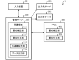
- FIG. 1 is a configuration diagram of a calculation result protection system 1.
- an input device 10 a management server (calculation result distribution device) 100, an FPGA (offload destination device) 300, an output destination server 201, and an output destination server 202 are connected via a network. configured.
- the input device 10 requests the management server 100 to perform a process of calculating an output value D2 (calculation result) from an input value D1 (hereinafter referred to as offload process) as a process of offloading to the FPGA 300. That is, the input device 10 transmits the input value D1 to the management server 100.
- the offload destination device is not limited to the FPGA 300, and any device as exemplified below may be used.
- ⁇ GPU Graphics Processing Unit
- FPU Floating Point Unit
- DSP Digital Signal Processor
- the management server 100 offloads the offload processing received from the input device 10 to the FPGA 300.
- the FPGA 300 returns the output value D2 obtained by executing the accepted offload process to the management server 100.
- the management server 100 distributes the output value D2 obtained from the FPGA 300 to the distribution destination device.
- the distribution destination devices are a total of three devices: the input device 10, the output destination server 201, and the output destination server 202.
- the management server 100 also checks the detailed status of the distribution destination device.
- the offload process is, for example, a process in which information about a device whose security is to be verified is used as an input value D1, and an output value D2 such as a security reliability score is calculated from the input value D1.
- an output value D2 such as a security reliability score
- a signature indicating who performed the calculation is also prepared.
- a protected area (first protected area) 110 is prepared in the memory within the management server 100.
- Protected area 110 protects stored data from unauthorized data access.
- the protected area 110 is an area (enclave) prepared in the memory of the management server 100 in which data access authority is protected, and data can be protected by restricting access authority to some applications.
- the protected area 110 is prepared for the purpose of preventing software with weaker privileges from being compromised when software with strong privileges is attacked.
- Software with strong authority includes, for example, the OS (Operating System), drivers, BIOS (Basic Input Output System), and VMM (Virtual Machine Manager).
- the management server 100 configures a protected area 110 in which programs such as signatures and encryption can be executed while protecting information.
- the protected area 110 is a place where integrity can be ensured by adding a signature/signature verification program, for example.
- the protected area 110 is an isolated place with limited access authority, and confidentiality can be ensured by adding an encryption program. It is desirable that all the data inside the protected area 110 is securely protected, but even if it is not completely protected, secret information (such as a private key in public key cryptography) among the internal data can be protected. It can also be used if it is securely protected.
- the protected area 110 of the management server 100 includes a signature verification section 111, a signature adding section 112, a common key distribution section 113, and a data output section 114, and each of these processing sections Data used for processing is stored in the protected area 110.
- the signature verification unit 111 refers to the device information of the other device sent from the other device, and determines that the verification has passed if the other device has a protection area (data protection ability). Distribution destination devices that have passed the verification become targets for distribution of the output value D2. This ensures that information sent from the management server 100 to another device is stored in a protected area within the other device, so information leakage from other devices to the distribution destination device can be suppressed before distribution.
- the device information of the other device is information used in attestation, which is a technique for confirming the capabilities of the protected area, such as address information of the protected area of the other device and information of applications within the protected area.
- the signature verification unit 111 may confirm the reliability of another device (such as the input device 10 ) with which the management server 100 communicates by verifying its signature. Therefore, the signature verification unit 111 verifies a signature made on at least one of the information exemplified below.
- CA third party
- the signature adding unit 112 adds a signature to allow other devices to confirm the reliability of the management server 100 itself. Note that regarding what information to attach a signature to, it is sufficient to use information obtained by replacing each information of the other device verified by the signature verification unit 111 with each information of the management server 100.
- the common key distribution unit 113 generates a common key shared by a plurality of communication partners, which is used when encrypting the output value (calculation result) of the FPGA 300, and distributes the common key to other devices.
- the common key distribution unit 113 generates a common key CK that is shared by multiple distribution destination devices (such as the input device 10). Then, the common key distribution unit 113 generates first encrypted data for each distribution destination device by encrypting the common key CK using the public key PK that is paired with the private key SK that each distribution destination device has individually. do. Further, the common key distribution unit 113 distributes the generated first encrypted data to each distribution destination device, thereby causing each distribution destination device to decrypt the common key CK.
- the data output unit 114 generates second encrypted data by encrypting the output value D2 (calculation result) of the FPGA 300 using the common key CK generated by the common key distribution unit 113 (see FIG. 4 for details). Then, the data output unit 114 distributes the generated second encrypted data to each distribution destination device, thereby causing each distribution destination device to decrypt the output value D2.
- the common key CK generated by the common key distribution unit 113 may be sent to the FPGA 300, and second encrypted data may be generated by encrypting the output value D2 on the FPGA 300 (see FIG. 19 for details).
- the FPGA 300 includes a signature verification section 301 and a signature adding section 302.
- the signature verification unit 301 verifies the management server 100 by verifying the signature assigned by the signature assignment unit 112 of the management server 100 that is the offload source.
- the signature adding unit 302 adds a signature to the output value of the FPGA 300 to allow other devices to confirm the reliability of the FPGA 300 itself.
- FIG. 2 is an explanatory diagram showing the processing of the input value D1 and the output value D2.
- the input device 10 creates a signature s10(D1) for the prepared input value D1 using its own key s10.
- the input device 10 sends the input value D1 and the signature s10 (D1) to the protected area 110 of the management server 100.
- the signature verification unit 111 of the protected area 110 verifies the signature s10(D1).
- the signature attaching unit 112 replaces the signature s10(D1) that has passed the verification by the signature verifying unit 111 with a signature s100(D1) using its own key s100.
- the signature adding unit 112 requests the FPGA 300 to offload the input value D1 together with the signature s100(D1).
- FIG. 3 is an explanatory diagram showing the process of distributing the common key CK by the common key distribution unit 113.
- the common key distribution unit 113 distributes the common key CK to be shared by a plurality of distribution destination devices in the following procedure in order to perform encryption accompanying the distribution process of the output value D2 shown in FIG.
- Step 1 The common key distribution unit 113 distributes the public key PK10 of the input device 10, the public key PK201 of the output destination server 201, and the public key of the output destination server 202 as verified public keys PK for each distribution destination device. Obtain the PK202 from the CA or distribution destination device in advance.
- the common key distribution unit 113 generates one common key CK to be shared by multiple distribution destination devices.
- the common key distribution unit 113 generates a plurality of encrypted data by encrypting the common key CK with the public key PK of each distribution destination device.
- the encrypted data PK10(CK) for the input device 10 is obtained by encrypting the common key CK with the public key PK10 of the input device 10.
- the common key distribution unit 113 distributes the generated plurality of encrypted data to each distribution destination device. For example, encrypted data PK10(CK) is distributed to the input device 10, encrypted data PK201(CK) is distributed to the output destination server 201, and encrypted data PK202(CK) is distributed to the output destination server 202.
- Each distribution destination device obtains the common key CK from step 2 by decrypting the distributed encrypted data using its own private key SK paired with the public key PK from step 1. .
- the input device 10 obtains the common key CK in step 2 by decrypting the distributed encrypted data PK10(CK) using its own private key SK10.
- FIG. 4 is an explanatory diagram showing the distribution process of the output value D2 by the data output unit 114.
- the data output unit 114 can ensure the safety of the output value D2 by encrypting the output value D2 using the common key CK shown in FIG. 3 according to the following procedure and then distributing it.
- the data output unit 114 receives the output value D2 received from the offload destination FPGA 300 and its signature s300(D2).
- the entire data obtained by connecting the received output value D2 and its signature s300(D2) will be indicated by the symbol "
- the data output unit 114 obtains encrypted data CK(D2
- FIG. 19 is an explanatory diagram when the FPGA 300 performs encryption instead of the management server 100, as a modification of FIG. 4.
- (Procedure 1) and (Procedure 2) in FIG. 4 are replaced with the following (Procedure 1B) and (Procedure 2B).
- (procedure 3) and (procedure 4) are executed similarly to FIG. 4.
- the FPGA 300 obtains encrypted data CK(D2
- the data output unit 114 receives encrypted data CK(D2
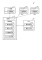
- FIG. 5 is a configuration diagram of a modification of the calculation result protection system 1 in which a protection area (second protection area) is provided in the device to which the output value D2 is distributed.
- FIG. 6 is an explanatory diagram showing the distribution process of the common key CK in the case of FIG. 5.
- the process of decrypting the common key CK in step 5 of FIG. 3 has been changed so that it is performed within the protected area of each device.
- FIG. 7 is an explanatory diagram showing the distribution process of the output value D2 in the case of FIG.
- FIGS. 5 to 7 prevent the output value D2 from being accessed illegally from the outside, thereby improving security strength.
- FIGS. 8 to 16 The details of the processing in FIGS. 2 to 4 will be described below with reference to FIGS. 8 to 16.
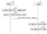
- FIG. 8 is a sequence diagram showing the process of confirming in advance that the device to which the output value D2 is distributed is a reliable partner.
- each device of the calculation result protection system 1 verifies other devices by challenge and response authentication without directly exchanging secret information such as passwords.
- the management server 100 confirms the public key PK10 of the input device 10 in S101-S104. Specifically, the management server 100 sends the random number R1 to the input device 10 (S101). The input device 10 uses its own private key SK10 as the random number R1 to generate a signature SK10(R1) (S102). The input device 10 sends its own public key PK10 and signature SK10(R1) to the management server 100 (S103). The signature verification unit 111 of the management server 100 verifies the sent public key PK10 with the signature SK10(R1) (S104). If the confirmation in S104 is successful, the process advances to the next step S111. On the other hand, if the confirmation in S104 fails, an error message is returned to the input device 10 of the communication partner. In each subsequent process, if signature verification fails, an error message is returned to the communication partner.
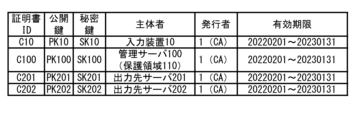
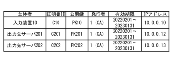
- FIG. 11 is a table showing a list of certificates issued by a CA serving as a third-party organization.
- This table contains the certificate ID, the public key included in the certificate, the private key paired with the public key, the entity that manages the private key, and the issuer (CA that issues the certificate). , and the expiration date of the certificate.
- Each device of the calculation result protection system 1 (for example, the management server 100) can obtain a public key (for example, the public key PK10 of the input device 10) whose reliability is guaranteed within the validity period by a certificate from the CA. Certificates are used in an environment called PKI (Public Key Infrastructure).
- PKI Public Key Infrastructure
- PKI uses various encryption technologies such as RSA cryptography and elliptic curve cryptography to perform authentication and attestation of the communication partner based on the guarantee of the certificate issued by a third party (CA).
- CA third party
- Each device obtains its own certificate and the private key and public key pair attached to that certificate from the CA in advance.
- the public key of another device is not obtained from the CA, but is sent to the other device.
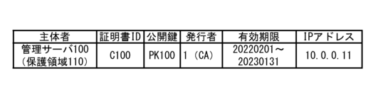
- FIG. 12 is a table showing a list of reliable communication partners that the management server 100 has.
- this table also includes the IP address of the subject's device linked to the public key. It is associated as device information.
- the device information of the other device, the address of the protected area of the other device (not shown), the information of the application in the protected area (not shown), etc. are also searched through the process of S114. This can be confirmed in the process of S134, which will be described later.
- this table also includes entries for the output destination servers 201 and 202 notified in S120, which will be described later. Note that the state of the table in FIG. 12 is the state after the output destination servers 201 and 202 have been confirmed in steps S131 to S134 described below.
- the input device 10 confirms the public key PK100 of the management server 100 in S111-S114. Specifically, the input device 10 sends the random number R2 to the management server 100 (S111). The signature adding unit 112 of the management server 100 uses its own private key SK100 as the random number R2 to generate a signature SK100(R2) (S112). The management server 100 sends its own public key PK100 and signature SK100(R2) to the input device 10 (S113). The input device 10 confirms the sent public key PK100 with the signature SK100(R2) (S114). The input device 10 sends information on the output destination servers 201 and 202 that need to be confirmed from now on to the management server 100 (S120).
- FIG. 13 is a table showing a list of communication partners held by each device other than the management server 100, such as the input device 10. This table has the same data format as FIG. 12. Similar to FIG. 12, the entry of the management server 100, which is a reliable partner for the input device 10, is registered in the table of FIG. 13 as a result of S111-S114.
- the management server 100 confirms the public key PK201 of the output destination server 201 in S131-S134.
- the management server 100 sends the random number R3 to the output destination server 201 (S131).
- the output destination server 201 uses its own private key SK201 as the random number R3 to generate a signature SK201(R3) (S132).
- the output destination server 201 sends its own public key PK201 and signature SK201(R3) to the management server 100 (S133).
- the signature verification unit 111 of the management server 100 verifies the sent public key PK201 with the signature SK201(R3) (S134).
- FIG. 14 is a table that shows a list of destination devices for which the output value D2 is distributed, which the management server 100 has.
- This table contains the request ID issued for each distribution destination device with the same output value D2, the destination indicating the distribution destination device with the same output value D2, and the information (certificate) in Figure 11 issued for that destination.
- the ID of the document, the public key of the recipient), and the IP address shown in FIG. 12 are associated with each other.
- three devices input device 10, output destination server 201, output destination server 202 with the same request ID "R01" are a set of distribution destination devices for the same output value D2.
- the management server 100 sequentially adds the devices confirmed in the process of FIG. 8 to the table of FIG. 14.
- FIG. 15 is a table showing a list of common keys CK that the management server 100 has.
- the common key CK issued for each request ID shown in FIG. 14 is registered in this table. If you want to distribute the output value D3 to two devices (input device 10, output destination server 201) apart from the distribution destination device of the output value D2, the management server 100 sends a new request ID "R02" and the The combination of the distribution destination device and the new common key CK2 issued for its R02 may be added to the table of FIG. 14 and the table of FIG. 15.
- FIG. 9 is a sequence diagram showing the distribution process of the common key CK.
- the management server 100 creates a common key CK to be shared by multiple distribution destination devices (S201).
- the management server 100 creates encrypted data PK10(CK) by encrypting the common key CK using the public key PK10 of the input device 10 confirmed in FIG. 8 (S202).
- the management server 100 sends the encrypted data PK10 (CK) to the input device 10 (S203).
- the input device 10 obtains the common key CK by decrypting the encrypted data PK10(CK) with its own private key SK10 (S204).
- the above is a process when the input device 10 is the distribution destination device, but S202 to S204 are executed for each distribution destination device of the output value D2. As shown below, other distribution destination devices also execute the process of FIG. 9 in the same way.
- the distribution destination device in S203 is the output destination server 201
- the public key PK10 used to create the encrypted data in S202 is replaced with the public key PK201 of the output destination server 201 confirmed in FIG. 8.
- the private key SK10 used to decrypt the encrypted data is replaced with the private key SK201 of the output destination server 201.
- the public key PK10 used to create the encrypted data in S202 is replaced with the public key PK202 of the output destination server 202 confirmed in FIG. 8.
- the private key SK10 used to decrypt the encrypted data is replaced with the private key SK202 of the output destination server 202.
- FIG. 10 is a sequence diagram showing the distribution process of the output value D2.
- the management server 100 acquires the output value D2, its signature s300 (D2), and its verification public key PKs from the offload destination FPGA 300 (S301). Therefore, the FPGA 300 is prepared in advance with a private key SKs for generating the signature s300 (D2) and a public key PKs for verifying it.
- the management server 100 creates encrypted data CK(D2
- the management server 100 sends the encrypted data CK(D2
- the input device 10 decrypts and obtains data D2
- the input device 10 decrypts the signature s300(D2) with the public key PKs and verifies whether it is valid as the signature of the output value D2 (S305). If the signature verification in S305 is successful, it can be confirmed that the data has not been tampered with.
- the above is a process when the input device 10 is the distribution destination device, but S303 and S304 are executed for each distribution destination device (output destination server 201, output destination server 202) of the output value D2.
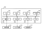
- FIG. 16 is a hardware configuration diagram of each device of the calculation result protection system 1.
- Each device of the calculation result protection system 1 includes a CPU 901, RAM 902, ROM 903, HDD 904, communication I/F 905, input/output I/F 906, media I/F 907, and TPM (Trusted Platform Module) 908. It is configured as a computer 900 having a computer 900.
- Communication I/F 905 is connected to external communication device 915.
- the input/output I/F 906 is connected to the input/output device 916.
- the media I/F 907 reads and writes data from the recording medium 917.
- the CPU 901 controls each unit by executing a program (also called an application or an abbreviated application) read into the RAM 902 . This program can also be distributed via a communication line or recorded on a recording medium 917 such as a CD-ROM.
- TPM 908 is used, such as to form a protected area within RAM 902.
- the management server 100 of the present invention generates a common key CK that is shared by multiple distribution destination devices (such as the input device 10), Encrypted data PK10 (CK) is generated for each distribution destination device by encrypting the common key CK using the public key PK that is paired with the private key SK that each distribution destination device has individually, and the generated encrypted data a common key distribution unit 113 that causes each distribution destination device to decrypt the common key CK by distributing PK10(CK) to each distribution destination device; It has a data output unit 114 that causes each distribution destination device to decrypt the output value D2 by distributing encrypted data CK(D2) in which the output value D2 is encrypted using the common key CK to each distribution destination device. It is characterized by
- the management server 100 since the same common key CK is used when sending data to multiple distribution destination devices, the management server 100 does not need to generate and hold multiple common keys CK. Therefore, the cost of managing security resources can be reduced by integrated management of the common key CK. Furthermore, the processing load on the FPGA 300 that calculates the output value D2 can be reduced. In addition, the encryption and decryption processes using the common key CK require less load than the encryption and decryption processes using the private key SK and public key PK. Decryption processing can be executed with low load. Therefore, the burden of transmitting the same calculation result to multiple destinations using a reliable method can be reduced.
- the management server 100 has a protection area 110 that protects stored data from unauthorized data access, It is characterized in that data used for processing by the common key distribution unit 113 and data used for processing by the data output unit 114 are stored within the protected area 110.
- encryption keys such as the common key CK are safely stored in the protected area 110 within the management server 100.
- the present invention is a calculation result protection system 1 having the above-mentioned management server 100 and a distribution destination device, At least some of the distribution destination devices have a protection area 10p that protects stored data from unauthorized data access,
- the management server 100 further includes a signature verification unit 111 that verifies each distribution destination device within the protected area 110, The signature verification unit 111 verifies whether the distribution destination device has the protected area 10p by referring to the device information of the distribution destination device, determines that the distribution destination device having the protected area 10p passes the verification, and distributes the passed distribution. It is characterized by distributing generated encrypted data PK10 (CK) to the destination device.
- CK generated encrypted data
- the calculation result protection system 1 further includes an FPGA 300 that calculates the output value D2, The FPGA 300 sends the calculated output value D2 and its own signature to the management server 100, The data output unit 114 distributes the encrypted data CK(D2) and the signature of the FPGA 300 to each distribution destination device, The distribution destination device verifies the output value D2 obtained by decrypting the encrypted data CK(D2) and the signature of the FPGA 300 within the protected area 10p.
- Calculation result protection system 10 Input device (distribution destination device) 10p protected area (second protected area) 100 Management server (calculation result distribution device) 110 Protected area (first protected area) 111 Signature verification section (verification section) 112 Signature adding unit 113 Common key distribution unit 114 Data output unit 201 Output destination server (distribution destination device) 201p protected area (second protected area) 202 Output destination server (distribution destination device) 202p protected area (second protected area) 300 FPGA (offload destination device) 301 Signature verification section 302 Signature adding section
Landscapes
- Engineering & Computer Science (AREA)
- Computer Security & Cryptography (AREA)
- Computer Networks & Wireless Communication (AREA)
- Signal Processing (AREA)
- Storage Device Security (AREA)
Abstract
Description
FaaSでは、例えば、入力装置からの入力値に対して出力値を計算する処理が、クラウドサーバなどの管理サーバからクラウド上のFPGAにオフロードされる。FPGAは、入力値に対して出力値を計算し、その計算した出力値を管理サーバに送る。
まず、第三者機関であるCA(Certificate Authority)は、サービス利用者が使用する入力装置10zと、サービス提供者が使用するFPGA300zが生成した公開鍵・秘密鍵ペアの公開鍵を含む証明書を両者に発行する。発行された両者は、それぞれのもつ証明書・秘密鍵を用いて両者で共用される共通鍵CKを事前に生成する。
次に、FPGA300zは、計算した出力値D2に対して共通鍵CKを用いて暗号化した暗号化データCK(D2)を、管理サーバ100zを介して入力装置10zに送信する。入力装置10zは、受信した暗号化データCK(D2)に対して共通鍵CKを用いて復号することで、安全に出力値D2を得られる。
図18では、出力値D2の配布先装置が、図17の入力装置10zと、新たに追加された出力先サーバ201z、202zとで合計3つの装置である。そのため、FPGA300zは、入力装置10zとで共用される共通鍵CK1に加え、出力先サーバ201zとで共用される共通鍵CK2と、出力先サーバ202zとで共用される共通鍵CK3とを個別に用意し、その署名を検証する必要がある。
同様に、FPGA300zは、出力値D2を共通鍵CK2で暗号化した暗号化データCK2(D2)を出力先サーバ201zに送信し、出力値D2を共通鍵CK3で暗号化した暗号化データCK3(D2)を出力先サーバ202zに送信する。
このように、FPGA300zは、共通鍵CK1~CK3を生成したり、共通鍵CK1~CK3の署名を検証したり、共通鍵CK1~CK3で暗号化したりする処理を配布先装置ごとに個別に行う必要がある。その処理負担がFPGA300zにかかってしまうため、FPGA300zに出力値D2の計算処理をオフロードする場合でも、処理効率が落ちてしまっていた。
本発明は、複数の配布先装置で共用される共通鍵を生成し、
各前記配布先装置が個別に有する秘密鍵とペアになる公開鍵を用いて、前記共通鍵を暗号化した第1暗号化データを前記配布先装置ごとに生成し、生成した前記第1暗号化データを前記配布先装置ごとに配布することで、各前記配布先装置に前記共通鍵を復号させる共通鍵配布部と、
前記共通鍵を用いて計算結果が暗号化された第2暗号化データを前記配布先装置ごとに配布することで、各前記配布先装置に前記計算結果を復号させるデータ出力部とを有することを特徴とする。
計算結果保護システム1は、入力装置10と、管理サーバ(計算結果配布装置)100と、FPGA(オフロード先装置)300と、出力先サーバ201と、出力先サーバ202とがネットワークで接続されて構成される。
入力装置10は、FPGA300にオフロードする処理として、入力値D1から出力値D2(計算結果)を計算する処理(以下、オフロード処理)を管理サーバ100に依頼する。つまり、入力装置10は、入力値D1を管理サーバ100に送信する。
・GPU(Graphics Processing Unit)
・FPU(Floating Point Unit)
・DSP(Digital Signal Processor)
そのため、管理サーバ100内のメモリには、保護領域(第1保護領域)110が用意される。
保護領域110は、強い権限を持ったソフトウェアが攻撃された場合に、弱い権限を持ったソフトウェアまで侵害されるのを防ぐ目的で用意される。強い権限を持ったソフトウェアとは、例えば、OS(Operating System)、ドライバ、BIOS(Basic Input Output System)、VMM(Virtual Machine Manager)である。
保護領域110は、内部のすべてのデータが安全に守られている場合が望ましいが、完全に守られていなくても、内部のデータのうちの秘密の情報(公開鍵暗号技術における秘密鍵など)が安全に守られている場合も利用可能とする。
署名検証部111は、例えば、他装置から送付された他装置の機器情報を参照して、他装置が保護領域(データの保護能力)を有している場合に、検証に合格と判定する。検証に合格した配布先装置は、出力値D2の配布対象となる。これにより、管理サーバ100から他装置に送付された情報が、他装置内の保護領域に格納されることが保証されるので、配布先装置の他装置からの情報流出を配布前に抑制できる。
他装置の機器情報は、例えば、他装置の保護領域のアドレス情報や、保護領域内のアプリケーションの情報など、保護領域などの能力を確認する技術であるアテステーションに用いられる情報である。
・第三者機関(CA)が発行する証明書。または、その証明書に含まれる他装置の公開鍵。
・他装置から発行された乱数情報。
・他装置のアドレス情報(IPアドレスなど)。
・他装置の公開鍵に紐づいた他装置の機器情報。
共通鍵配布部113は、FPGA300の出力値(計算結果)を暗号化するときに用いられる複数の通信相手に共用される共通鍵を生成し、その共通鍵を他装置に配布する。
または、共通鍵配布部113が生成した共通鍵CKをFPGA300に送り、FPGA300上で出力値D2を暗号化した第2暗号化データを生成してもよい(詳細は図19)。
署名検証部301は、オフロード元である管理サーバ100の署名付与部112が付与した署名を検証することで、管理サーバ100を検証する。
署名付与部302は、FPGA300自身の信頼性を他装置に確認させるための署名を、FPGA300の出力値に付与する。
入力装置10は、用意した入力値D1に対して、自身の鍵s10を用いて署名s10(D1)を作成する。入力装置10は、入力値D1と署名s10(D1)とを管理サーバ100の保護領域110に送付する。
保護領域110の署名検証部111は、署名s10(D1)を検証する。署名付与部112は、署名検証部111の検証に合格した署名s10(D1)に対して、自身の鍵s100を用いた署名s100(D1)に置き換える。署名付与部112は、署名s100(D1)とともに入力値D1のオフロード処理をFPGA300に依頼する。
署名付与部302は、計算した出力値D2に対して、自身の鍵s300を用いて署名s300(D2)を作成する。FPGA300は、出力値D2とその署名s300(D2)とを、管理サーバ100の保護領域110に送付する。
署名検証部111は、受信した出力値D2とその署名s300(D2)とを検証する。署名付与部112は、検証に合格した署名s300(D2)を署名SK100(D2)に置き換える。
データ出力部114は、配布先装置である入力装置10と、出力先サーバ201と、出力先サーバ202とに出力値D2と署名SK100(D2)とを配布する。
共通鍵配布部113は、図2で示した出力値D2の配布処理に伴う暗号化を行うために、複数の配布先装置で共用する共通鍵CKを以下の手順で配布する。
(手順1) 共通鍵配布部113は、配布先装置ごとに検証済みの公開鍵PKとして、入力装置10の公開鍵PK10と、出力先サーバ201の公開鍵PK201と、出力先サーバ202の公開鍵PK202とをCAや配布先装置などから事前に取得しておく。
(手順2) 共通鍵配布部113は、複数の配布先装置で共用する共通鍵CKを1つ生成する。
(手順3) 共通鍵配布部113は、配布先装置ごとの公開鍵PKで共通鍵CKを暗号化した暗号化データを複数生成する。例えば、入力装置10向けの暗号化データPK10(CK)は、入力装置10の公開鍵PK10で共通鍵CKを暗号化したものである。
(手順5) 各配布先装置は、手順1の公開鍵PKとペアになる自身の秘密鍵SKを用いて、配布された暗号化データを復号することで、手順2の共通鍵CKを取得する。例えば、入力装置10は、自身の秘密鍵SK10を用いて、配布された暗号化データPK10(CK)を復号することで、手順2の共通鍵CKを取得する。
以上の手順により、管理サーバ100が生成した1つの共通鍵CKが、保護領域110から各配布先装置に安全に配布された。管理サーバ100は、配布先装置の台数に関係なく共通鍵CKを1つ生成すればよいので、負荷が下がる。
データ出力部114は、以下の手順により図3で示した共通鍵CKを用いて出力値D2の暗号化を行ってから配布することで、出力値D2の安全性を確保できる。
(手順1) データ出力部114は、オフロード先のFPGA300から受信した出力値D2と、その署名s300(D2)とを受信する。以下、受信した出力値D2と、その署名s300(D2)とをつなげた全体のデータを「D2||s300(D2)」のように、記号「||」で示す。
(手順2) データ出力部114は、共通鍵CKを用いてデータD2||s300(D2)の暗号化を行うことで、暗号化データCK(D2||s300(D2))を取得する。
(手順3) データ出力部114は、暗号化データCK(D2||s300(D2))を各配布先装置に配布する。
(手順4) 入力装置10などの各配布先装置は、共通鍵CKを用いて暗号化データCK(D2||s300(D2))からデータD2||s300(D2)を復号する。また各配布先装置は、出力値D2と、その署名s300(D2)とを検証する。
このように、データ出力部114は、配布先装置が複数であっても、配布した共通鍵CKを用いた暗号化を一度行えばよい。よって、配布先装置が増えても、暗号化の手間が増えずに済む。
(手順1B) FPGA300は、管理サーバ100から受信した共通鍵CKを用いてデータD2||s300(D2)の暗号化を行うことで、暗号化データCK(D2||s300(D2))を取得する。
(手順2B) データ出力部114は、オフロード先のFPGA300から暗号化データCK(D2||s300(D2))を受信する。
図1の計算結果保護システム1と比較すると、出力値D2の配布先装置である各装置(入力装置10と、出力先サーバ201と、出力先サーバ202と)は、それぞれ自身に保護領域10p、201p、202pを有している。
図6は、図5の場合における共通鍵CKの配布処理を示す説明図である。図5では図3の(手順5)で共通鍵CKを復号する処理が、各装置の保護領域内で行うように変更されている。
図7は、図5の場合における出力値D2の配布処理を示す説明図である。図5では図4の(手順4)で暗号化データCK(D2||s300(D2))を復号する処理が、各装置の保護領域内で行うように変更されている。
以上、図5~図7の構成により、出力値D2が外部から不正アクセスされずに済み、セキュリティ強度が向上する。以下、図8~図16を参照して、図2~図4の処理の詳細を説明する。
このシーケンス図では、計算結果保護システム1の各装置が、チャレンジ/レスポンス認証(challenge and response authentication)により、パスワードなどの秘密の情報を直接やり取りすることなく、他装置を確認する。
具体的には、管理サーバ100は、乱数R1を入力装置10に送付する(S101)。入力装置10は、乱数R1に自身の秘密鍵SK10を用いて、署名SK10(R1)を生成する(S102)。
入力装置10は、自身の公開鍵PK10および署名SK10(R1)を管理サーバ100に送付する(S103)。管理サーバ100の署名検証部111は、送付された公開鍵PK10を署名SK10(R1)で確認する(S104)。S104の確認に成功した場合、次のS111に処理を進める。
一方、S104の確認に失敗した場合、エラーメッセージを通信相手の入力装置10に返信する。以降の各処理においても、署名の確認に失敗した場合、エラーメッセージを通信相手に返信する。
このテーブルには、証明書IDと、証明書に含まれる公開鍵と、その公開鍵とペアになる秘密鍵と、秘密鍵を管理する主体者と、証明書を発行するCAである発行者と、証明書の有効期限とが対応付けられている。計算結果保護システム1の各装置(例えば管理サーバ100)は、CAから証明書により有効期限内で信頼性が保障された公開鍵(例えば入力装置10の公開鍵PK10)を取得できる。
証明書は、PKI(Public Key Infrastructure)という環境で利用される。PKIでは、RSA暗号や楕円曲線暗号などの各種の暗号化技術を利用して、第三者機関(CA)による証明書発行先の保証をもとにした、通信相手の認証やAttestationを行うことができる。
各装置は、自身の証明書およびその証明書に付属する秘密鍵&公開鍵のペアを、事前にCAから入手しておく。あるいは、各装置で、公開鍵&秘密鍵のペアを作成して、その公開鍵を使った証明書を事前にCAから入手しておく。一方、他装置の公開鍵は、CAから入手するのではなく、他装置に送付してもらう。
このテーブルには、図11で説明した各項目(証明書IDと、公開鍵と、主体者と、発行者と、有効期限)に加え、主体者の装置のIPアドレスが公開鍵に紐づいた機器情報として対応付けられている。つまり、他装置の主体者の列を検索キーとして、他装置の機器情報や、他装置の保護領域のアドレス(図示省略)、保護領域内のアプリケーションの情報(図示省略)なども、S114の処理や後記するS134の処理で確認できる。
また、このテーブルには、S101-S104で確認された入力装置10のエントリに加え、後記するS120で通知された出力先サーバ201,202のエントリも含まれる。なお、図12のテーブルの状態は、以下で説明するS131-S134により出力先サーバ201,202が確認された後の状態である。
具体的には、入力装置10は、乱数R2を管理サーバ100に送付する(S111)。管理サーバ100の署名付与部112は、乱数R2に自身の秘密鍵SK100を用いて、署名SK100(R2)を生成する(S112)。
管理サーバ100は、自身の公開鍵PK100および署名SK100(R2)を入力装置10に送付する(S113)。入力装置10は、送付された公開鍵PK100を署名SK100(R2)で確認する(S114)。
入力装置10は、これから確認が必要な出力先サーバ201,202の情報を管理サーバ100に送付する(S120)。
管理サーバ100は、乱数R3を出力先サーバ201に送付する(S131)。出力先サーバ201は、乱数R3に自身の秘密鍵SK201を用いて、署名SK201(R3)生成する(S132)。
出力先サーバ201は、自身の公開鍵PK201および署名SK201(R3)を管理サーバ100に送付する(S133)。管理サーバ100の署名検証部111は、送付された公開鍵PK201を署名SK201(R3)で確認する(S134)。
例えば、要求IDが同じ「R01」である3つの装置(入力装置10、出力先サーバ201、出力先サーバ202)が、同じ出力値D2の配布先装置となる集合である。管理サーバ100は、図8の処理で確認された装置を、図14のテーブルに順次追加する。
もし、出力値D2の配布先装置とは別に、出力値D3を2つの装置(入力装置10、出力先サーバ201)に配布したい場合、管理サーバ100は、新たな要求ID「R02」と、その配布先装置と、そのR02用に発行された新たな共通鍵CK2との組み合わせを、図14のテーブルおよび図15のテーブルに追加すればよい。
管理サーバ100は、複数の配布先装置で共用する共通鍵CKを作成する(S201)。管理サーバ100は、図8で確認した入力装置10の公開鍵PK10を用いて、共通鍵CKを暗号化した暗号化データPK10(CK)を作成する(S202)。管理サーバ100は、暗号化データPK10(CK)を入力装置10に送付する(S203)。
入力装置10は、自身の秘密鍵SK10で暗号化データPK10(CK)を復号することで、共通鍵CKを取得する(S204)。
[S203の配布先装置=出力先サーバ201の場合] S202で暗号化データの作成に用いられる公開鍵PK10が、図8で確認した出力先サーバ201の公開鍵PK201に置き換わる。S204で暗号化データの復号に用いられる秘密鍵SK10が、出力先サーバ201の秘密鍵SK201に置き換わる。
[S203の配布先装置=出力先サーバ202の場合] S202で暗号化データの作成に用いられる公開鍵PK10が、図8で確認した出力先サーバ202の公開鍵PK202に置き換わる。S204で暗号化データの復号に用いられる秘密鍵SK10が、出力先サーバ202の秘密鍵SK202に置き換わる。
管理サーバ100は、出力値D2と、その署名s300(D2)と、その検証用の公開鍵PKsを、オフロード先のFPGA300から取得する(S301)。そのため、FPGA300には、署名s300(D2)を生成するための秘密鍵SKsと、その検証用の公開鍵PKsとが事前に用意される。
管理サーバ100は、共通鍵CKを用いてデータD2||s300(D2)の暗号化を行うことで、暗号化データCK(D2||s300(D2))を作成する(S302)。管理サーバ100は、暗号化データCK(D2||s300(D2))と、公開鍵PKsとを、入力装置10に送付する(S303)。
以上は、入力装置10を配布先装置とした場合の処理であるが、S303、S304は、出力値D2の配布先装置ごとに(出力先サーバ201、出力先サーバ202)実行される。
計算結果保護システム1の各装置は、CPU901と、RAM902と、ROM903と、HDD904と、通信I/F905と、入出力I/F906と、メディアI/F907と、TPM(Trusted Platform Module)908とを有するコンピュータ900として構成される。
通信I/F905は、外部の通信装置915と接続される。入出力I/F906は、入出力装置916と接続される。メディアI/F907は、記録媒体917からデータを読み書きする。さらに、CPU901は、RAM902に読み込んだプログラム(アプリケーションや、その略のアプリとも呼ばれる)を実行することにより、各部を制御する。そして、このプログラムは、通信回線を介して配布したり、CD-ROM等の記録媒体917に記録して配布したりすることも可能である。
さらに、TPM908は、RAM902内に保護領域を形成するためなどに使用される。
本発明の管理サーバ100は、複数の配布先装置(入力装置10など)で共用される共通鍵CKを生成し、
各配布先装置が個別に有する秘密鍵SKとペアになる公開鍵PKを用いて、共通鍵CKを暗号化した暗号化データPK10(CK)を配布先装置ごとに生成し、生成した暗号化データPK10(CK)を配布先装置ごとに配布することで、各配布先装置に共通鍵CKを復号させる共通鍵配布部113と、
共通鍵CKを用いて出力値D2が暗号化された暗号化データCK(D2)を配布先装置ごとに配布することで、各配布先装置に出力値D2を復号させるデータ出力部114とを有することを特徴とする。
また、共通鍵CKを用いた暗号化処理や復号処理は、秘密鍵SK・公開鍵PKを用いた暗号化処理や復号処理よりも負荷が少ないので、頻度の高い出力値D2の暗号化処理や復号処理を低負荷で実行できる。よって、複数の宛先に同じ計算結果を信頼性ある手法で送信する場合の負担を少なくできる。
共通鍵配布部113の処理に用いられるデータ、および、データ出力部114の処理に用いられるデータが、保護領域110内に格納されることを特徴とする。
少なくとも一部の配布先装置が、不正なデータアクセスから格納されるデータを保護する保護領域10pを有しており、
管理サーバ100が、さらに、各配布先装置を保護領域110内で検証する署名検証部111を有しており、
署名検証部111が、配布先装置の機器情報を参照して配布先装置が保護領域10pを有するか否かを検証し、保護領域10pを有する配布先装置を検証に合格とし、その合格した配布先装置に生成した暗号化データPK10(CK)を配布することを特徴とする。
FPGA300が、計算した出力値D2と、自身の署名とを管理サーバ100に送付し、
データ出力部114が、暗号化データCK(D2)と、FPGA300の署名とを配布先装置ごとに配布し、
配布先装置が、暗号化データCK(D2)を復号した出力値D2と、FPGA300の署名とを保護領域10p内で検証することを特徴とする。
10 入力装置(配布先装置)
10p 保護領域(第2保護領域)
100 管理サーバ(計算結果配布装置)
110 保護領域(第1保護領域)
111 署名検証部(検証部)
112 署名付与部
113 共通鍵配布部
114 データ出力部
201 出力先サーバ(配布先装置)
201p 保護領域(第2保護領域)
202 出力先サーバ(配布先装置)
202p 保護領域(第2保護領域)
300 FPGA(オフロード先装置)
301 署名検証部
302 署名付与部
Claims (5)
- 複数の配布先装置で共用される共通鍵を生成し、
各前記配布先装置が個別に有する秘密鍵とペアになる公開鍵を用いて、前記共通鍵を暗号化した第1暗号化データを前記配布先装置ごとに生成し、生成した前記第1暗号化データを前記配布先装置ごとに配布することで、各前記配布先装置に前記共通鍵を復号させる共通鍵配布部と、
前記共通鍵を用いて計算結果が暗号化された第2暗号化データを前記配布先装置ごとに配布することで、各前記配布先装置に前記計算結果を復号させるデータ出力部とを有することを特徴とする
計算結果配布装置。 - 前記計算結果配布装置は、不正なデータアクセスから格納されるデータを保護する第1保護領域を有しており、
前記共通鍵配布部の処理に用いられるデータ、および、前記データ出力部の処理に用いられるデータは、前記第1保護領域内に格納されることを特徴とする
請求項1に記載の計算結果配布装置。 - 請求項2に記載の計算結果配布装置と、前記配布先装置とを有する計算結果保護システムであって、
少なくとも一部の前記配布先装置は、不正なデータアクセスから格納されるデータを保護する第2保護領域を有しており、
前記計算結果配布装置は、さらに、各前記配布先装置を前記第1保護領域内で検証する検証部を有しており、
前記検証部は、前記配布先装置の機器情報を参照して前記配布先装置が前記第2保護領域を有するか否かを検証し、前記第2保護領域を有する前記配布先装置を検証に合格とし、その合格した前記配布先装置に生成した前記第1暗号化データを配布することを特徴とする
計算結果保護システム。 - 前記計算結果保護システムは、さらに、前記計算結果を計算するオフロード先装置を有しており、
前記オフロード先装置は、計算した前記計算結果と、自身の署名とを前記計算結果配布装置に送付し、
前記データ出力部は、前記第2暗号化データと、前記オフロード先装置の署名とを前記配布先装置ごとに配布し、
前記配布先装置は、前記第2暗号化データを復号した前記計算結果と、前記オフロード先装置の署名とを前記第2保護領域内で検証することを特徴とする
請求項3に記載の計算結果保護システム。 - 計算結果配布装置は、共通鍵配布部と、データ出力部とを有しており、
前記共通鍵配布部は、
複数の配布先装置で共用される共通鍵を生成し、
各前記配布先装置が個別に有する秘密鍵とペアになる公開鍵を用いて、前記共通鍵を暗号化した第1暗号化データを前記配布先装置ごとに生成し、生成した前記第1暗号化データを前記配布先装置ごとに配布することで、各前記配布先装置に前記共通鍵を復号させ、
前記データ出力部は、前記共通鍵を用いて計算結果が暗号化された第2暗号化データを前記配布先装置ごとに配布することで、各前記配布先装置に前記計算結果を復号させることを特徴とする
計算結果配布方法。
Priority Applications (3)
| Application Number | Priority Date | Filing Date | Title |
|---|---|---|---|
| PCT/JP2022/019759 WO2023218514A1 (ja) | 2022-05-10 | 2022-05-10 | 計算結果配布装置、計算結果保護システム、および、計算結果配布方法 |
| JP2024520109A JP7794303B2 (ja) | 2022-05-10 | 2022-05-10 | 計算結果保護システム、および、計算結果配布方法 |
| US18/861,955 US20250293861A1 (en) | 2022-05-10 | 2022-05-10 | Calculation result distribution device, calculation result protection system, and calculation result distribution method |
Applications Claiming Priority (1)
| Application Number | Priority Date | Filing Date | Title |
|---|---|---|---|
| PCT/JP2022/019759 WO2023218514A1 (ja) | 2022-05-10 | 2022-05-10 | 計算結果配布装置、計算結果保護システム、および、計算結果配布方法 |
Publications (1)
| Publication Number | Publication Date |
|---|---|
| WO2023218514A1 true WO2023218514A1 (ja) | 2023-11-16 |
Family
ID=88729944
Family Applications (1)
| Application Number | Title | Priority Date | Filing Date |
|---|---|---|---|
| PCT/JP2022/019759 Ceased WO2023218514A1 (ja) | 2022-05-10 | 2022-05-10 | 計算結果配布装置、計算結果保護システム、および、計算結果配布方法 |
Country Status (3)
| Country | Link |
|---|---|
| US (1) | US20250293861A1 (ja) |
| JP (1) | JP7794303B2 (ja) |
| WO (1) | WO2023218514A1 (ja) |
Citations (3)
| Publication number | Priority date | Publication date | Assignee | Title |
|---|---|---|---|---|
| US20180255023A1 (en) * | 2017-03-02 | 2018-09-06 | UnifyID | Privacy-preserving system for machine-learning training data |
| JP2020177223A (ja) * | 2019-04-15 | 2020-10-29 | 株式会社アクセル | 演算装置、演算システム、及び演算方法 |
| WO2021166787A1 (ja) * | 2020-02-20 | 2021-08-26 | Eaglys株式会社 | 情報処理システム、情報処理装置、情報処理方法、および、情報処理プログラム |
Family Cites Families (8)
| Publication number | Priority date | Publication date | Assignee | Title |
|---|---|---|---|---|
| US6041408A (en) * | 1996-06-28 | 2000-03-21 | Hitachi, Ltd. | Key distribution method and system in secure broadcast communication |
| US6813357B1 (en) * | 1998-12-25 | 2004-11-02 | Matsushita Communication Industrial Co., Ltd. | Exclusive key sharing method |
| US8104073B2 (en) * | 2007-08-10 | 2012-01-24 | Juniper Networks, Inc. | Exchange of network access control information using tightly-constrained network access control protocols |
| JP5776432B2 (ja) * | 2011-08-11 | 2015-09-09 | ソニー株式会社 | 情報処理装置、および情報処理方法、並びにプログラム |
| JP6277494B2 (ja) * | 2015-07-29 | 2018-02-14 | パナソニックIpマネジメント株式会社 | アプリケーション制御システム及びアプリケーション制御方法 |
| CN110495135B (zh) * | 2017-04-14 | 2022-06-28 | 三菱电机株式会社 | 密钥管理系统、通信设备以及密钥共享方法 |
| US10936460B2 (en) * | 2018-06-19 | 2021-03-02 | Dell Products, L.P. | Method and apparatus for identifying and reporting faults at an information handling system |
| US11438162B2 (en) * | 2020-03-19 | 2022-09-06 | Arista Networks, Inc. | Network device authentication |
-
2022
- 2022-05-10 WO PCT/JP2022/019759 patent/WO2023218514A1/ja not_active Ceased
- 2022-05-10 US US18/861,955 patent/US20250293861A1/en active Pending
- 2022-05-10 JP JP2024520109A patent/JP7794303B2/ja active Active
Patent Citations (3)
| Publication number | Priority date | Publication date | Assignee | Title |
|---|---|---|---|---|
| US20180255023A1 (en) * | 2017-03-02 | 2018-09-06 | UnifyID | Privacy-preserving system for machine-learning training data |
| JP2020177223A (ja) * | 2019-04-15 | 2020-10-29 | 株式会社アクセル | 演算装置、演算システム、及び演算方法 |
| WO2021166787A1 (ja) * | 2020-02-20 | 2021-08-26 | Eaglys株式会社 | 情報処理システム、情報処理装置、情報処理方法、および、情報処理プログラム |
Also Published As
| Publication number | Publication date |
|---|---|
| JP7794303B2 (ja) | 2026-01-06 |
| JPWO2023218514A1 (ja) | 2023-11-16 |
| US20250293861A1 (en) | 2025-09-18 |
Similar Documents
| Publication | Publication Date | Title |
|---|---|---|
| RU2756048C2 (ru) | Адресация доверенной среды исполнения с использованием ключа шифрования | |
| US10972265B2 (en) | Addressing a trusted execution environment | |
| US20220114249A1 (en) | Systems and methods for secure and fast machine learning inference in a trusted execution environment | |
| CN114616797B (zh) | 处理对控制存储在多个服务器处的信息的请求 | |
| US11212095B2 (en) | Allowing restricted external access to devices | |
| JP2020528224A (ja) | 信頼できる実行環境におけるスマート契約動作のセキュアな実行 | |
| WO2022142790A1 (zh) | 区块链系统的链外数据访问方法和系统 | |
| KR20190108580A (ko) | 서명키를 사용한 신뢰 실행 환경의 어드레싱 기법 | |
| US20160087995A1 (en) | Procedure For Platform Enforced Storage in Infrastructure Clouds | |
| CN113259123B (zh) | 一种区块链数据写入、访问方法及装置 | |
| CN118337430B (zh) | 针对多方交互数据实现可信传输与反向授权处理的系统、方法、装置、处理器及其存储介质 | |
| EP3574429A1 (en) | Addressing a trusted execution environment using clean room provisioning | |
| US20250211619A1 (en) | Remote attestation transport layer security and split trust encryption | |
| JP2022522555A (ja) | セミトラステッドな中継者を使用したセキュアなメッセージ受け渡し | |
| US11398906B2 (en) | Confirming receipt of audit records for audited use of a cryptographic key | |
| KR101311059B1 (ko) | 취소 정보 관리 | |
| CN114826702B (zh) | 数据库访问密码加密方法、装置和计算机设备 | |
| JP7794303B2 (ja) | 計算結果保護システム、および、計算結果配布方法 | |
| US11405201B2 (en) | Secure transfer of protected application storage keys with change of trusted computing base | |
| JP6830635B1 (ja) | データ管理方法 | |
| Satar et al. | Data Privacy and Integrity Issues Scheme in Cloud Computing: A Survey | |
| Chang et al. | T-ABE: A practical ABE scheme to provide trustworthy key hosting on untrustworthy cloud | |
| WO2025187037A1 (ja) | データ共有装置およびデータ共有方法 | |
| CN119766542A (zh) | 基于非对称加密的数据离线审核方法及装置 | |
| HK40029518B (zh) | 在可信执行环境中安全地执行智能合约操作 |
Legal Events
| Date | Code | Title | Description |
|---|---|---|---|
| 121 | Ep: the epo has been informed by wipo that ep was designated in this application |
Ref document number: 22941596 Country of ref document: EP Kind code of ref document: A1 |
|
| WWE | Wipo information: entry into national phase |
Ref document number: 2024520109 Country of ref document: JP |
|
| WWE | Wipo information: entry into national phase |
Ref document number: 18861955 Country of ref document: US |
|
| NENP | Non-entry into the national phase |
Ref country code: DE |
|
| 122 | Ep: pct application non-entry in european phase |
Ref document number: 22941596 Country of ref document: EP Kind code of ref document: A1 |
|
| WWP | Wipo information: published in national office |
Ref document number: 18861955 Country of ref document: US |