WO2023210538A1 - ベルト、及び被服 - Google Patents
ベルト、及び被服 Download PDFInfo
- Publication number
- WO2023210538A1 WO2023210538A1 PCT/JP2023/015974 JP2023015974W WO2023210538A1 WO 2023210538 A1 WO2023210538 A1 WO 2023210538A1 JP 2023015974 W JP2023015974 W JP 2023015974W WO 2023210538 A1 WO2023210538 A1 WO 2023210538A1
- Authority
- WO
- WIPO (PCT)
- Prior art keywords
- conductive
- fiber fabric
- electrode
- layer
- clothing
- Prior art date
- Legal status (The legal status is an assumption and is not a legal conclusion. Google has not performed a legal analysis and makes no representation as to the accuracy of the status listed.)
- Ceased
Links
Images


Classifications
-
- D—TEXTILES; PAPER
- D06—TREATMENT OF TEXTILES OR THE LIKE; LAUNDERING; FLEXIBLE MATERIALS NOT OTHERWISE PROVIDED FOR
- D06M—TREATMENT, NOT PROVIDED FOR ELSEWHERE IN CLASS D06, OF FIBRES, THREADS, YARNS, FABRICS, FEATHERS OR FIBROUS GOODS MADE FROM SUCH MATERIALS
- D06M11/00—Treating fibres, threads, yarns, fabrics or fibrous goods made from such materials, with inorganic substances or complexes thereof; Such treatment combined with mechanical treatment, e.g. mercerising
- D06M11/83—Treating fibres, threads, yarns, fabrics or fibrous goods made from such materials, with inorganic substances or complexes thereof; Such treatment combined with mechanical treatment, e.g. mercerising with metals; with metal-generating compounds, e.g. metal carbonyls; Reduction of metal compounds on textiles
-
- A—HUMAN NECESSITIES
- A41—WEARING APPAREL
- A41D—OUTERWEAR; PROTECTIVE GARMENTS; ACCESSORIES
- A41D1/00—Garments
- A41D1/002—Garments adapted to accommodate electronic equipment
-
- A—HUMAN NECESSITIES
- A41—WEARING APPAREL
- A41F—GARMENT FASTENINGS; SUSPENDERS
- A41F9/00—Belts, girdles, or waistbands for trousers or skirts
- A41F9/002—Free belts
-
- A—HUMAN NECESSITIES
- A61—MEDICAL OR VETERINARY SCIENCE; HYGIENE
- A61B—DIAGNOSIS; SURGERY; IDENTIFICATION
- A61B5/00—Measuring for diagnostic purposes; Identification of persons
- A61B5/24—Detecting, measuring or recording bioelectric or biomagnetic signals of the body or parts thereof
- A61B5/25—Bioelectric electrodes therefor
- A61B5/251—Means for maintaining electrode contact with the body
- A61B5/256—Wearable electrodes, e.g. having straps or bands
-
- A—HUMAN NECESSITIES
- A61—MEDICAL OR VETERINARY SCIENCE; HYGIENE
- A61B—DIAGNOSIS; SURGERY; IDENTIFICATION
- A61B5/00—Measuring for diagnostic purposes; Identification of persons
- A61B5/24—Detecting, measuring or recording bioelectric or biomagnetic signals of the body or parts thereof
- A61B5/25—Bioelectric electrodes therefor
- A61B5/263—Bioelectric electrodes therefor characterised by the electrode materials
- A61B5/27—Conductive fabrics or textiles
-
- A—HUMAN NECESSITIES
- A61—MEDICAL OR VETERINARY SCIENCE; HYGIENE
- A61B—DIAGNOSIS; SURGERY; IDENTIFICATION
- A61B5/00—Measuring for diagnostic purposes; Identification of persons
- A61B5/68—Arrangements of detecting, measuring or recording means, e.g. sensors, in relation to patient
- A61B5/6801—Arrangements of detecting, measuring or recording means, e.g. sensors, in relation to patient specially adapted to be attached to or worn on the body surface
- A61B5/6802—Sensor mounted on worn items
- A61B5/6804—Garments; Clothes
- A61B5/6805—Vests, e.g. shirts or gowns
-
- A—HUMAN NECESSITIES
- A61—MEDICAL OR VETERINARY SCIENCE; HYGIENE
- A61B—DIAGNOSIS; SURGERY; IDENTIFICATION
- A61B5/00—Measuring for diagnostic purposes; Identification of persons
- A61B5/68—Arrangements of detecting, measuring or recording means, e.g. sensors, in relation to patient
- A61B5/6801—Arrangements of detecting, measuring or recording means, e.g. sensors, in relation to patient specially adapted to be attached to or worn on the body surface
- A61B5/683—Means for maintaining contact with the body
- A61B5/6831—Straps, bands or harnesses
-
- D—TEXTILES; PAPER
- D06—TREATMENT OF TEXTILES OR THE LIKE; LAUNDERING; FLEXIBLE MATERIALS NOT OTHERWISE PROVIDED FOR
- D06M—TREATMENT, NOT PROVIDED FOR ELSEWHERE IN CLASS D06, OF FIBRES, THREADS, YARNS, FABRICS, FEATHERS OR FIBROUS GOODS MADE FROM SUCH MATERIALS
- D06M15/00—Treating fibres, threads, yarns, fabrics, or fibrous goods made from such materials, with macromolecular compounds; Such treatment combined with mechanical treatment
- D06M15/19—Treating fibres, threads, yarns, fabrics, or fibrous goods made from such materials, with macromolecular compounds; Such treatment combined with mechanical treatment with synthetic macromolecular compounds
- D06M15/37—Macromolecular compounds obtained otherwise than by reactions only involving carbon-to-carbon unsaturated bonds
- D06M15/643—Macromolecular compounds obtained otherwise than by reactions only involving carbon-to-carbon unsaturated bonds containing silicon in the main chain
-
- D—TEXTILES; PAPER
- D06—TREATMENT OF TEXTILES OR THE LIKE; LAUNDERING; FLEXIBLE MATERIALS NOT OTHERWISE PROVIDED FOR
- D06M—TREATMENT, NOT PROVIDED FOR ELSEWHERE IN CLASS D06, OF FIBRES, THREADS, YARNS, FABRICS, FEATHERS OR FIBROUS GOODS MADE FROM SUCH MATERIALS
- D06M15/00—Treating fibres, threads, yarns, fabrics, or fibrous goods made from such materials, with macromolecular compounds; Such treatment combined with mechanical treatment
- D06M15/693—Treating fibres, threads, yarns, fabrics, or fibrous goods made from such materials, with macromolecular compounds; Such treatment combined with mechanical treatment with natural or synthetic rubber, or derivatives thereof
-
- A—HUMAN NECESSITIES
- A61—MEDICAL OR VETERINARY SCIENCE; HYGIENE
- A61B—DIAGNOSIS; SURGERY; IDENTIFICATION
- A61B2562/00—Details of sensors; Constructional details of sensor housings or probes; Accessories for sensors
- A61B2562/16—Details of sensor housings or probes; Details of structural supports for sensors
- A61B2562/164—Details of sensor housings or probes; Details of structural supports for sensors the sensor is mounted in or on a conformable substrate or carrier
Definitions
- the present invention relates to a belt and clothing having electrodes capable of detecting biopotential.
- Patent Document 1 describes a fibrous fabric interface formed by an individually woven combination of conductive fibers that are selectively exposed and non-conductive fibers that impart elasticity to the fibrous structure.
- a fiber fabric interface formed by weaving threads containing conductive fibers (conductive fibers) has unevenness unique to the fibers on the surface and has low adhesion to the body. Therefore, in conventional electrodes such as textile fabric interfaces, the electrodes sometimes pick up noise due to body movements. Further, the sheet resistance of conventional electrodes was about 10 -1 ⁇ / ⁇ .
- this textile fabric interface is sometimes used by being woven into clothing, but if this clothing is washed multiple times, some of it may peel off or fall off, lose its conductivity, and become inoperable. Ta.
- detergents and linen liquids used for laundry contain various chemicals such as acidic and alkaline chemicals, so textile fabric interfaces can react with these chemicals and lose their conductivity during washing. There is. Noise resistance during these body movements, durability against washing, etc. are issues related to all fiber fabric interfaces, including not only those made of woven or knitted yarns, but also non-woven fabrics.
- electrodes for measuring biopotential and the like include not only fiber fabric interfaces but also conductive elastomer fabrics.
- electrodes made only of conductive elastomer fabric also have the same problems with noise resistance and durability as with fiber fabric interfaces.
- An object of the present invention is to provide a belt or clothing using an electrode that has higher noise resistance and durability than electrodes formed only from conductive fiber fabric or conductive elastomer fabric.
- the clothing according to claim 1 of the present invention includes a clothing material to be worn by a wearer, and an electrode provided on the surface of the clothing material at a position that contacts the wearer's body when worn.
- the electrode includes a conductive fiber fabric layer that is a conductive fiber fabric, and a conductive elastomer layer containing an elastomer composition and a conductive filler formed on at least one surface of the conductive fiber fabric layer. It is a clothing characterized by having the following.
- the clothing according to claim 2 of the present invention is the clothing according to claim 1, wherein the electrode contacts a part of the wearer's torso at the same height as the xiphoid process. It is.
- the belt according to claim 3 of the present invention includes a belt member having elasticity and a surface of the belt member that is provided at a position that comes into contact with the wearer's body when the belt member is wrapped around the wearer.
- the electrode comprises a conductive fiber fabric layer which is a conductive fiber fabric, and an elastomer composition and a conductive material formed on at least one surface of the conductive fiber fabric layer.
- the belt is characterized by having a conductive elastomer layer containing a conductive filler.
- the belt according to claim 4 of the present invention is the belt according to claim 3, wherein the electrode contacts a part of the wearer's torso at the same height as the xiphoid process. It is.
- noise resistance and durability are improved compared to those formed only from conductive fiber fabric or conductive elastomer fabric.
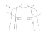
- FIG. 3 is a diagram showing the appearance of clothing C according to the present embodiment.
- FIG. 3 is a diagram showing an example of the configuration of a conductive fiber fabric layer 11.
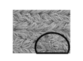
- a photograph of a cross section of sample A1 processed five times.
- FIG. 1 is a diagram showing the appearance of clothing C according to this embodiment.
- the clothing C is worn by the wearer P, and contacts the wearer's body to detect the bioelectrical potential of the wearer P.
- Bio information is information obtained from detected biopotentials, and includes, for example, electrocardiogram, heartbeat, respiration, pulse wave, body temperature, myoelectricity, electroencephalogram, eyeball potential, blood pressure, sweat rate, blood sugar level, humidity, etc. .
- the biological information may be any information that can be obtained by the wearer's P's body touching the electrode area.
- biological information is electrocardiogram.
- the "inside" of clothing C etc. is the side near the wearer's P body, and the "outside” is the side far from the wearer's P body.
- the clothing C shown in FIG. 1 is clothing worn by the wearer P on the upper body.
- a detection area F1 is provided on the front of the clothing C between the chest and abdomen of the wearer P.
- FIG. 2 is a diagram showing an example of a cross section of the clothing C in the detection area F1.
- the clothing C has an electrode 1 and an insulating fiber fabric 2 in the detection area F1.
- the electrode 1 is provided inside the detection area F1 in the clothing C so as to be in contact with the body of the wearer P. Therefore, this clothing C is an example of clothing that includes a clothing material to be worn by the wearer and an electrode provided on the surface of the clothing material at a position that contacts the wearer's body when worn.
- the clothing C includes a transmitter that transmits biological signals detected by the electrode 1 to an external device, wiring that connects the transmitter and the electrode 1 in a communicable manner, and insulation that protects the wiring and the electrode 1. It may have members, etc.
- the insulating member is, for example, a urethane sheet that is bonded to the insulating fiber fabric 2 by heating and pressurizing.
- the insulating fiber fabric 2 is a clothing material worn by the wearer P, and is a fabric that constitutes the majority of the clothing C.
- This insulating fiber fabric 2 is a fibrous fabric formed by weaving or knitting fibers that do not easily conduct electricity (referred to as insulating fibers).
- the insulating fiber fabric 2 is, for example, a knitted fabric, a woven fabric, a nonwoven fabric, or the like.
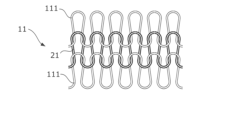
- FIG. 3 is a diagram showing an example of the structure of the insulating fiber fabric 2.
- the insulating fiber fabric 2 shown in FIG. 3 is formed by knitting insulating fibers 21.
- the insulating fibers 21 are highly elastic fibers (elastic fibers) so that they can easily adhere to the body of the wearer P.
- the elastic fibers are preferably fibers with an expansion/contraction ratio of at least 50%.
- This elastic fiber is, for example, polyurethane.
- the elastic fiber used for the insulating fiber 21 is not limited to polyurethane, and may be, for example, elastic polyester, natural rubber fiber, heat-shrinkable nylon, or the like.
- the insulating fiber 21 may be a composite yarn formed of multiple types of insulating fibers.
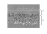
- the electrode 1 shown in FIG. 2 has a conductive fiber fabric layer 11, a conductive elastomer layer 12, and a dipping layer 13.
- the conductive fiber fabric layer 11 is the outermost layer
- the conductive elastomer layer 12 is the innermost layer
- the dipping layer 13 is a layer included in the conductive fiber fabric layer 11 and is a layer sandwiched between the conductive fiber fabric layer 11 and the conductive elastomer layer 12.
- the conductive fiber fabric layer 11 is an example of a conductive fiber fabric layer that is a conductive fiber fabric.
- the conductive fiber fabric layer 11 is a fiber fabric formed by weaving or knitting threads containing conductive fibers (referred to as conductive fibers).
- the conductive fiber fabric layer 11 shown in FIG. 2 is formed integrally with the insulating fiber fabric 2.
- the conductive fiber fabric layer 11 shown in FIG. Note that the conductive fiber fabric layer 11 is not limited to being formed integrally with the insulating fiber fabric 2.
- the conductive fiber fabric layer 11 may be formed as a knitted fabric, a woven fabric, etc. using a thread containing conductive fibers separately from the insulating fiber fabric 2, and may be sewn onto the insulating fiber fabric 2.
- FIG. 4 is a diagram showing an example of the structure of the conductive fiber fabric layer 11.
- the conductive fiber fabric layer 11 is formed by weaving conductive composite yarn 111 into the above-mentioned insulating fiber 21, as shown in FIG.
- the conductive fiber fabric layer 11 may be integrally formed with the insulating fiber fabric 2 by weaving common insulating fibers 21 so that there is no step difference.
- FIG. 5 is a diagram showing an example of the conductive composite yarn 111.
- This conductive composite yarn 111 is a composite yarn formed by winding conductive fibers 1111 around elastic fibers 1110.
- the elastic fibers 1110 are fibers with relatively high elasticity.
- the elastic fibers 1110 are desirably fibers with an expansion/contraction ratio of at least 50%.
- This elastic fiber 1110 is, for example, polyurethane.
- the elastic fibers 1110 may be, for example, elastic polyester, natural rubber fibers, heat-shrinkable nylon, or the like. Moreover, this elastic fiber 1110 may be used in common with the insulating fiber 21.
- the conductive fibers 1111 are conductive fibers, and are made by adding a conductive substance to non-conductive fibers (referred to as non-conductive fibers).
- the conductive substance is, for example, a metal such as silver, copper, stainless steel, nickel, or aluminum. Further, the conductive substance may be a non-metal such as carbon or a conductive polymer.
- the conductive composite yarn 111 shown in FIG. 5 is an example of a yarn containing conductive fibers, and is an example of a conductive composite yarn formed by winding conductive fibers around elastic fibers.
- the conductive fiber fabric layer 11 is formed by weaving the conductive composite yarn 111 into the insulating fiber 21.
- the conductive fiber fabric layer 11 is formed by weaving the conductive composite yarn 111 into the insulating fiber 21. This is an example of a fabric layer.
- the conductive substance is added to the non-conductive fibers by, for example, wet coating treatment such as electroless metal plating treatment.
- the conductive fiber 1111 shown in FIG. 5 is, for example, a thread made of silver-plated nylon.
- the ratio of silver to nylon may be at least 10 mass percent, but preferably at least 20 mass percent, and preferably at least 30 mass percent. is more desirable.
- the method for adding a conductive substance to non-conductive fibers is not limited to wet film treatment, and may also be, for example, vapor deposition, sputtering, adhesion of metal foil, impregnation, etc.
- the conductive fiber 1111 may be formed, for example, by impregnating acrylic fiber with copper sulfide.
- the non-conductive fiber used for the conductive fiber 1111 is, for example, nylon. Note that this non-conductive fiber may be any fiber whose conductivity is below a predetermined threshold value. Thus, the non-conductive fibers may be, for example, cellulose, natural fibers such as raw silk, or other synthetic fibers. By using natural fibers as the non-conductive fibers, the clothing C can be worn even if the wearer P is allergic to synthetic fibers.
- the conductive fibers 1111 do not need to contain non-conductive fibers as long as they have conductivity. Further, the conductive fiber fabric layer 11 does not need to be woven into the insulating fibers 21 as long as it has conductivity as a whole.
- the conductive fiber fabric layer 11 may be formed by knitting only the conductive composite yarns 111.
- the conductive composite yarn 111 shown in FIG. 5 is formed by wrapping the conductive fibers 1111 twice around an elastic fiber 1110 as a core yarn. That is, the conductive composite yarn 111 is formed from a double covered yarn.
- this conductive composite yarn 111 is made by first winding a lower yarn 1111a, which is a conductive fiber 1111, around an elastic fiber 1110, and then winding an upper yarn 1111b, which is a conductive fiber 1111, in the opposite direction thereon. It is formed by attaching it.
- the conductive elastomer layer 12 is formed by applying a paste to the inner surface of the conductive fiber fabric layer 11 and drying the paste.
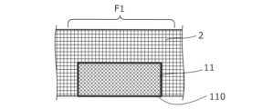
- FIG. 6 is a diagram showing the state of the conductive fiber fabric layer 11 before applying the paste.
- the conductive fiber fabric layer 11 is formed on at least one surface of the insulating fiber fabric 2 so that there is no step, for example.
- the surface 110 is the side of the conductive fiber fabric layer 11 that is closer to the wearer P (not shown in FIG. 6), that is, the inner surface.
- FIG. 7 is a diagram showing the state of the conductive fiber fabric layer 11 when the paste is applied. As shown in FIG. 7, a paste containing an elastomer composition 120 and a conductive filler 121 is applied to the inner surface 110 of the conductive fiber fabric layer 11.
- the elastomer composition 120 shown in FIG. 7 is obtained by dissolving an elastomer in a solvent.
- this elastomer include silicone rubber, fluororubber, nitrile rubber, acrylic rubber, styrene rubber, chloroprene rubber, ethylene propylene rubber, and urethane rubber.
- the solvent for dissolving the above-mentioned elastomer for example, aliphatic hydrocarbons, aromatic hydrocarbons, ethers, haloalkanes, carboxylic acid amides, sulfoxides, etc. are used.
- aliphatic hydrocarbons examples include pentane, hexane, cyclohexane, heptane, methylcyclohexane, ethylcyclohexane, octane, decane, and tetradecane.
- Aromatic hydrocarbons include benzene, toluene, ethylbenzene, xylene, trifluoromethylbenzene, benzotrifluoride, and the like.
- the ethers include diethyl ether, diisopropyl ether, dibutyl ether, cyclopentyl methyl ether, cyclopentyl ethyl ether, ethylene glycol dimethyl ether, ethylene glycol diethyl ether, diethylene glycol dimethyl ether, 1,4-dioxane, 1,3-dioxane, tetrahydrofuran, and the like.
- haloalkanes include dichloromethane, chloroform, 1,1-dichloroethane, 1,2-dichloroethane, 1,1,1-trichloroethane, and 1,1,2-trichloroethane.
- Carboxylic acid amides include N,N-dimethylformamide, N,N-dimethylacetamide, and the like.
- Sulfoxides include dimethyl sulfoxide, diethyl sulfoxide, and the like. Note that the solvent may be one type of these, or a mixture of two or more of these at any ratio.
- the content of the elastomer in the paste is preferably 3% by mass or more, more preferably 5% by mass or more, and even more preferably 7% by mass or more, based on the entire solid content of the paste. Further, the content of the elastomer in the paste is preferably 30% by mass or less, more preferably 25% by mass or less, and even more preferably 20% by mass or less, based on the entire solid content of the paste. preferable.
- the conductive filler 121 shown in FIG. 7 is a fine solid that has conductivity.
- This conductive filler 121 is not particularly limited, but includes, for example, copper, silver, gold, nickel, tin, lead, zinc, bismuth, antimony, metal powder made of an alloy of these, a conductive organic compound, and a conductive carbon material. It contains at least one kind, or two or more kinds of these.
- the conductive filler preferably contains silver or copper from the viewpoint of high conductivity or high availability. That is, it is preferable that the conductive filler contains silver powder or copper powder.
- the conductive filler may be coated with other metals.
- the shape of the conductive filler there are no restrictions on the shape of the conductive filler, but conventionally used shapes such as dendritic, spherical, and flaky shapes can be used.
- the paste described above is manufactured by adding a conductive filler 121 to an elastomer composition 120.
- the added conductive fillers 121 come into contact with each other in the elastomer composition 120 and impart conductivity to the entire paste.
- the content of the conductive filler in the paste is preferably 60% by mass or more, more preferably 65% by mass or more, and still more preferably 70% by mass or more, based on the entire solid content of the paste. preferable. Further, the content of the conductive filler in the paste is preferably 90% by mass or less, more preferably 88% by mass or less, and 85% by mass or less based on the entire solid content of the paste. is even more preferable.
- the paste described above may contain silica particles, if necessary. By including these silica particles, it is possible to improve the hardness and mechanical strength of a cured product formed from the paste.
- the silica particles preferably have a specific surface area of 10 to 400 m2/g, more preferably 20 to 400 m2/g.
- the median diameter D50 is preferably 1 to 100 nm, more preferably 5 to 20 nm.
- the particle size of the silica particles can be defined as the average value of 200 arbitrarily selected silica particles, for example, by observing the paste or its cured product with a transmission electron microscope or the like and performing image analysis.
- the silica particles are not particularly limited, for example, fumed silica, calcined silica, precipitated silica, etc. can be used.
- only one type of silica particles may be used alone, or two or more types may be used in combination.
- the content of silica particles in the paste described above is preferably 1% by mass or more, more preferably 2% by mass or more, and preferably 3% by mass or more, based on the entire solid content of the paste. More preferred. Further, the content of silica particles in the paste is preferably 15% by mass or less, more preferably 12% by mass or less, and preferably 10% by mass or less based on the entire solid content of the paste. More preferred.
- the cured product of the paste can have appropriate mechanical strength. Furthermore, by controlling the content of silica particles to be equal to or less than the above upper limit, the cured product can have appropriate conductive properties.
- FIG. 8 is a diagram showing the state of the electrode 1 after the paste has been dried.
- the paste becomes the conductive elastomer layer 12 shown in FIG. 8, for example, by volatilizing a certain amount of the solvent.
- a conductive elastomer layer 12 is formed inside the surface 110 of the conductive fiber fabric layer 11. That is, this conductive elastomer layer 12 is an example of a conductive elastomer layer containing an elastomer composition and a conductive filler, which is formed on at least one surface of the conductive fiber fabric layer.
- the surface 110 of the conductive fiber fabric layer 11 is immersed in the applied paste. Then, by drying the soaked paste, a soaked layer 13 is formed on the surface 110 side of the conductive fiber fabric layer 11.
- the dipping layer 13 contains an elastomer composition 120 and a conductive filler 121 in the gaps between the fibers of the conductive fiber fabric layer 11 . Therefore, the conductive fiber fabric layer 11 including this dipped layer 13 on the surface 110 side is a conductive fibrous fabric layer having a dipped layer impregnated with the elastomer composition and the conductive filler on at least one surface. This is an example.
- the electrode 1 has a conductive elastomer layer 12 on the innermost side. Since the conductive elastomer layer 12 is formed by containing the elastomer composition 120, its surface is smoother than, for example, conductive fibers. Therefore, compared to other electrodes that do not have the conductive elastomer layer 12, the electrode 1 can easily adhere to the body of the wearer P without gaps and is less susceptible to noise.
- the dipping layer 13 has a structure in which a conductive filler 121 that is electrically connected to the conductive elastomer layer 12 is intricately inserted into the gap between the conductive composite yarns 111 forming the conductive fiber fabric layer 11 . Therefore, the dipping layer 13 strengthens the electrical conduction between the conductive fiber fabric layer 11 and the conductive elastomer layer 12.
- this electrode 1 is made by (1) forming a conductive fiber fabric layer 11 on at least one surface of the insulating fiber fabric 2, and (2) applying a paste to the inner surface 110 of the conductive fiber fabric layer 11. , and (3) drying the paste to form the conductive elastomer layer 12 (and immersion layer 13), but the steps for creating the electrode 1 are not limited to this.
- the electrode 1 may be created in the order of (2) ⁇ (1) ⁇ (3), or may be created in the order of (2) ⁇ (3) ⁇ (1).
- the step (1) is not limited to forming the conductive fiber fabric layer 11 integrally with the insulating fiber fabric 2 as described above. Therefore, for example, the electrode 1 can be made by (2) applying a paste to the inner surface 110 of the conductive fiber fabric layer 11 and then (1) applying the paste to the inner surface 110 of the conductive fiber fabric layer 11. (3) drying the paste to form the conductive elastomer layer 12.
- the myoelectric potential becomes noise.
- the electrode 1 is provided in the detection area F1 between the chest and abdomen of the wearer P in the clothing C and in contact with areas that are not easily affected by the myoelectric potential, such as the pectoralis major muscle and the rectus abdominis muscle.
- FIG. 9 is a diagram showing an example of the position of the detection area F1.
- the detection region F1 is preferably a region that is not easily influenced by myoelectric potentials such as the pectoralis major muscle and the rectus abdominis muscle, as described above.
- the detection area F1 shown in FIG. 9 is an area that contacts the skin covering the fifth rib r5 to the sixth rib r6 on the front surface of the torso of the wearer P.
- the detection region F1 may be a region of the wearer's P's torso that contacts the skin at the same height as the xiphoid process E. That is, the electrode 1 provided in the detection area F1 is an example of an electrode that contacts a part of the wearer's torso at the same height as the xiphoid process.
- FIG. 10 is a diagram showing an example of the position of the detection area F2.
- the detection area F2 is an area where electrodes were provided in the conventional technology.
- the detection region F2 shown in FIG. 10 is located at a position lower than the xiphoid process E in the torso of the wearer P.
- the detection area F2 shown in FIG. 10 is an area that contacts the skin covering from the seventh rib r7 to the eighth rib r8.
- the conductive fiber fabric layer 11 of the electrode 1 uses the conductive composite yarn 111 as the yarn containing conductive fibers, but the yarn is not limited to the composite yarn.
- the conductive fibers 1111 may be used as they are.
- the conductive fiber fabric layer 11 may be, for example, a fiber fabric formed by knitting conductive fibers, which are silver-plated nylon threads, into polyurethane elastic fibers.
- the conductive fiber fabric layer 11 is formed by weaving yarns containing conductive fibers, but it may be any fabric as long as it has conductivity.
- the conductive fiber fabric layer 11 is a fiber fabric in which a conductive substance is formed on the surface of an insulating fiber fabric that has no conductivity, or the surface of a non-conductive fiber fabric whose conductivity does not meet a certain level. It's okay.
- This conductive material is formed by, for example, depositing a film by plating.
- the conductive fiber fabric layer 11 may be a fiber fabric made of an insulating fabric woven with nylon and polyurethane and plated with silver.
- the conductive fiber fabric layer 11 in this modification has a conductive film layer, which is formed by depositing a conductive film on an insulating fiber fabric made of insulating fibers that insulate electricity, on at least one surface. This is an example of a fibrous fabric layer.
- the conductive elastomer layer 12 was formed by applying and drying one type of paste, but may be formed by sequentially applying two or more types of paste.
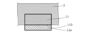
- FIG. 11 is a diagram showing an example of the initial stage of formation of the conductive elastomer layer 12 in a modified example. As shown in FIG. 11, a first paste is applied to the surface 110 of the conductive fiber fabric layer 11. This first paste, after drying, forms the first conductive elastomer layer 12a.
- FIG. 12 is a diagram showing an example in which the conductive elastomer layer 12 is being formed in a modified example. As shown in FIG. 12, a second paste is applied to the surface of the first conductive elastomer layer 12a. This second paste forms the second conductive elastomer layer 12b after drying.
- FIG. 13 is a diagram showing an example of the final stage of the conductive elastomer layer 12 in a modified example.
- the electrode 1 shown in FIG. 13 includes a conductive fiber fabric layer 11 with a dipping layer 13 formed therein, a first conductive elastomer layer 12a, and a second conductive elastomer layer 12b.
- a first conductive elastomer layer 12a is formed inside the dipping layer 13.
- the second conductive elastomer layer 12b is formed inside the first conductive elastomer layer 12a.
- the concentration of the conductive filler 121 may be a difference in the concentration of the conductive filler 121 (see FIG. 7) between the first paste and the second paste.
- the second paste in this modification has a higher concentration of conductive filler 121 than the first paste. That is, the first paste in this modification has a lower concentration of conductive filler than the second paste.
- the first conductive elastomer layer 12a is closer to the conductive fiber fabric layer 11 than the second conductive elastomer layer 12b, and has a thinner concentration of conductive filler 121.
- this conductive elastomer layer 12 in the modified example is an example of a conductive elastomer layer having a region where the concentration of the conductive filler becomes thinner as it approaches the conductive fiber fabric layer.
- This conductive elastomer layer 12 has a higher concentration of conductive filler 121 on the side farther away from the conductive fiber fabric layer 11 and closer to the body of the wearer P. Therefore, this conductive elastomer layer 12 contains a large amount of conductive filler 121 in the parts that are more easily exposed to impact, friction, etc. and easily peeled off, so it is more resistant to impact, friction, etc. than a layer with a uniform concentration. Expected to show gender.
- the electrode 1 was provided on the clothing C, but it may also be provided on the belt.
- FIG. 14 is a diagram showing an example of belt B in a modification.
- the belt B includes a stretchable belt member 2a and an electrode 1 provided on the surface of the belt member 2a.
- the electrode 1 is provided at a position where it comes into contact with the body of the wearer P when the belt B is wrapped around the wearer P.
- this belt B includes a belt member having elasticity, an electrode provided on the surface of the belt member at a position that contacts the wearer's body when the belt member is wrapped around the wearer, This is an example of a belt having
- FIG. 15 is a diagram showing an example of a state in which the belt B is worn in a modified example.
- Belt B is wound between the chest and abdomen of wearer P so that electrode 1 is placed in detection area F1.
- the detection area F1 shown in FIG. 15 is located at the same position as the detection area F1 shown in FIG. That is, the electrode 1 provided on the belt B is an example of an electrode that contacts a portion of the wearer's torso at the same height as the xiphoid process.
- the electrodes 1 of the belt B can come into contact with the body of the wearer P in the detection region F1 and detect biological signals.
- the electrode 1 since the electrode 1 has the conductive fiber fabric layer 11 and the conductive elastomer layer 12, it can easily adhere to the body of the wearer P and is not easily affected by noise.
- Example> ⁇ Experiment example> ⁇ Experiment A (simulated laundry experiment)> ⁇ Sample> The inventors of the present invention conducted an experiment (hereinafter referred to as Experiment A) in which a sample was subjected to a treatment simulating washing, and the appearance of the sample before and after the treatment was photographed and evaluated.
- the samples used in Experiment A were one consisting only of AGPoss (registered trademark, the same hereinafter) manufactured by Mitsufuji Co., Ltd.
- sample A1 (hereinafter referred to as sample A1), and one consisting only of AGPoss (registered trademark, the same hereinafter) manufactured by Mitsufuji Co., Ltd., and one consisting only of AGPoss (hereinafter referred to as sample A1) manufactured by Mitsufuji Co., Ltd.;
- sample A2 A sample (hereinafter referred to as sample A2) printed (coated and dried) with a registered trademark (the same applies hereinafter) was used.
- AGPoss is an example of the conductive fiber fabric layer 11.
- DuraQ is an example of the conductive elastomer layer 12.
- AGPoss used was a nylon polyurethane elastic fiber to which 10% by mass or more of silver was added by plating.
- DuraQ used a paste-like product in which silicone rubber was dissolved in a hydrocarbon solvent such as decane or tetradecane, and silver powder was added and mixed so that the solid content concentration was about 70% by mass. there was.
- Sample A2 was formed by applying a conductive paste in a direction substantially perpendicular to the grain of the AGPoss fibers and drying it. Sample A2 has DuraQ formed on 1.3 cm square of the surface of AGPoss. The concentration of the conductive filler in the conductive paste was 86% by mass, and the amount of paste adhered was 39.5 mg/cm 2 (milligrams per square centimeter).
- FIG. 16 is a flowchart showing the flow of an experiment on the influence of a load on an electrode by simulating washing.
- the experimenter performed the following steps S101 to S105 to apply a load simulating washing to the sample.
- the experimenter determines whether or not the sample has been processed a predetermined number of times (step S101), and if it is determined that the process has been processed the predetermined number of times (step S101; YES), the sample is placed under a scanning electron microscope (SEM). :Scanning Electron Microscope) and evaluated it (Step S102).
- SEM scanning electron microscope
- step S101 the experimenter repeated the processes from step S103 to step S105 while determining that the process had not been performed the prescribed number of times (step S101; NO).
- the experimenter first stretched and contracted the sample in both the vertical and horizontal directions 300 times at a stretching ratio of 50% (step S103).
- the stretch ratio is the percentage of the length increased by stretching with respect to the length of the sample under no load. In other words, in this stretching experiment, the sample is stretched up to 1.5 times its length.
- the experimenter immersed the sample in the linen liquid and stirred it for 20 hours (step S104).
- the linen liquid was prepared by adding 1.5 ml of hydrogen peroxide and 1.5 ml of a 30 w/v% aqueous sodium hydroxide solution to 1 liter of water.
- the temperature of the linen liquid is maintained at 85°C. Note that in the present invention, w/v% indicates the ratio of mass (grams) to a total volume of 100 milliliters.
- step S105 the experimenter dried the sample at 110° C. for 20 minutes.
- FIG. 17 is a photograph of the surface of untreated sample A1.
- FIG. 18 is a photograph of a cross section of untreated sample A1. Since these are unprocessed, the specified number of times mentioned above is 0. As shown in FIGS. 17 and 18, no damage to the silver plating formed on the surface of the fibers was observed in sample A1 in the untreated state.
- FIG. 19 is a photograph of the surface of sample A1 that has been treated five times.
- FIG. 20 is a photograph of a cross section of sample A1 that has been treated five times. The prescribed number of times is five. As shown in FIGS. 19 and 20, damage to the silver plating was observed in sample A1 by repeating the process from step S103 to step S105 described above five times.
- FIG. 21 is a photograph of the surface of untreated sample A2.
- FIG. 22 is a photograph of a cross section of untreated sample A2. Since these are unprocessed, the specified number of times mentioned above is 0. As shown in FIGS. 21 and 22, no damage was observed in the silver plating on the fiber surface of sample A2 in the untreated state. Further, since the surface of sample A2 was covered with DuraQ, which is an example of the conductive elastomer layer 12, the shape of the AGPoss fibers, which is an example of the conductive fiber fabric layer 11, was not visually recognized. As shown in FIG.
- This soaked layer 13 is a layer in which DuraQ is soaked in AGPoss fibers.
- FIG. 23 is a photograph of the surface of sample A2 that has been treated five times.
- FIG. 24 is a photograph of a cross section of sample A2 that has been treated five times. The prescribed number of times is five. As shown in FIGS. 23 and 24, no damage to the silver plating was observed in sample A2 even after the above-described treatment was repeated five times. Even after these five treatments, the above-mentioned immersion layer 13 had not disappeared.
- Experiment B electrode durability experiment
- Experiments have shown that the electrode 1 described above has improved durability against washing because it has the conductive elastomer layer 12.
- the inventors of the present application conducted an experiment (hereinafter referred to as Experiment B) in which a sample was subjected to a treatment simulating washing and the resistance to the treatment was evaluated. This resistance was evaluated by measuring the sheet resistance of the sample at each treatment time.
- Table 1 is a table in which changes in sheet resistance of the electrode 1 according to the present invention are recorded for each washing time.
- sample B2 shows the sheet resistance when electrode 1 was washed with a commercially available chlorine bleach.
- the electrode 1 in sample B2 is obtained by printing (coating and drying) the above-mentioned DuraQ on the surface of the above-mentioned AGPoss.
- sample B1 shows the sheet resistance when an electrode having the same structure as the conductive fiber fabric layer 11 described above was washed with a commercially available chlorine bleach.
- the electrode in sample B1 is composed only of the above-mentioned AGPoss.
- N/D indicates non-detection.
- sample B2 that is, electrode 1 according to the present invention
- sample B1 that is, the electrode without the conductive elastomer layer 12
- the sheet resistance was no longer detected after 60 minutes.
- the conductive elastomer layer 12 protects the conductive fiber fabric layer 11 and prevents the conductive material from peeling off due to friction, impact, etc. during washing.
- the conductive fiber fabric layer 11 is disposed below (that is, on the outside) of the conductive elastomer layer 12. Therefore, even if the conductive elastomer layer 12 breaks, the conductive fiber fabric layer 11 electrically connected to each broken conductive elastomer layer 12 is protected by the conductive elastomer layer 12. The conductivity of electrode 1 is maintained.
- the sheet resistance of the conventional electrode was 1.34 ⁇ 10 ⁇ 1 ⁇ / ⁇ .
- the sheet resistance of the electrode 1 is 3.40 ⁇ 10 ⁇ 2 ⁇ / ⁇ .
- the sheet resistance of the conventional electrode was about 1 ⁇ 10 -1 ⁇ / ⁇
- the sheet resistance of the electrode 1 according to the present invention was about 1 ⁇ 10 -3 ⁇ / ⁇ . It has improved to about ⁇ / ⁇ . That is, the electrode 1 has a lower sheet resistance than conventional electrodes. This is thought to be due to the effect of the immersion layer 13 in addition to the effect of the conductive elastomer layer 12.
- Experiment C (actual machine linen washing experiment)> The inventors of the present application conducted an experiment (hereinafter referred to as Experiment C) in which the samples were actually washed, the surface resistance values of the samples were measured each time the samples were washed, and the surface resistance values were evaluated.
- the washing in Experiment C was carried out at a preliminary washing temperature of 40°C and an actual washing temperature of 80°C for 10 minutes.
- a commercial washing machine SWX-60WU manufactured by Tokyo Rinsenki Kikai Seisakusho was used.
- As detergent 300 ml of 30 w/v % sodium hydroxide was used for each wash. It was expected that the pH would be 10 by using this detergent.
- 300 ml of 35 w/v % hydrogen peroxide was used for each wash. Drying performed after each wash was performed by heating the sample at 80° C. for 13 minutes.
- Table 2 is a table in which the surface resistance values of the electrodes are recorded for each number of times the clothing C according to the present invention was washed.
- sample C2 shows the surface resistance value of electrode 1 when clothing C was washed in an actual linen machine.
- the electrode 1 in sample C2 is obtained by coating and drying the above-mentioned DuraQ on the surface of the above-mentioned AGPoss, and its thickness is equivalent to six masks.
- DuraQ used here expresses the thickness in units called masks. This mask has layers each having a thickness of 125 ⁇ m (micrometers). Therefore, since this sample C2 is equivalent to six masks, it has a DuraQ layer (conductive elastomer layer 12) with a thickness of 750 ⁇ m (micrometers). Further, in this sample C2, a conductive paste having a conductive filler concentration of 71% by mass was used as a conductive paste which is a precursor of DuraQ.
- sample C1 shows the surface resistance value of the electrode when clothing provided with an electrode having the same configuration as the conductive fiber fabric layer 11 described above was washed using an actual linen machine.
- the electrode in sample C1 is composed only of the above-mentioned AGPoss.
- O/L indicates that the upper limit of measurement was exceeded.
- FIG. 25 is a graph showing Table 2 mentioned above.
- the reference line Q is a line indicating a surface resistance value of 1.0 ⁇ (ohm), and indicates the quality standard of the electrode. If the surface resistance value is lower than this reference line Q, the electrode satisfies the quality standards. On the other hand, if a surface resistance value of 1.0 ⁇ (ohm) or more indicated by this reference line Q is measured, the electrode does not meet the quality standards.
- the graph shown by the broken line in FIG. 25 represents the measurement results of sample C1 in Table 2.
- sample C1 no longer satisfies the quality standards after being washed 10 times, and after being washed more than 30 times, the surface resistance value exceeds the upper limit of measurement.
- sample C1 made of only AGPoss which is an example of the conductive fiber fabric layer 11, no longer satisfies the quality standards after just 10 washes.
- the graph shown by the solid line in FIG. 25 represents the measurement results of sample C2 in Table 2.
- sample C2 met the quality standards even after being washed 60 times, and stopped meeting the quality standards only after being washed more than 70 times.
- sample C2 which is an example of electrode 1 of the present invention, satisfies the quality standards even after washing 60 times.
- experiment D Noise resistance experiment
- the inventors of the present application conducted an experiment (hereinafter referred to as experiment D) to verify noise resistance using the electrode 1 of the invention according to the present application.
- the samples used in this experiment D are sample D1, which is an example of the prior art, and sample D2, which includes electrode 1, which is an example of the invention according to the present application.
- Sample D1 is a belt provided with electrodes consisting only of the conventional conductive fiber fabric layer 11.
- Sample D2 is a belt provided with an electrode 1 according to the invention of the present application, in which a conductive elastomer layer 12 is formed by applying a paste to a conductive fiber fabric layer 11 and drying it.
- the conductive fiber fabric layer 11 is the above-mentioned AGPoss.
- the conductive elastomer layer 12 is the above-mentioned DuraQ.
- the subject wears sample D1 and sample D2 so that the electrodes are located in detection area F2 shown in FIG. 9, performs four specified movements, and has electrocardiographic waveforms measured in each state. .
- “Walking” in Table 3 is a state of walking in time with a tempo of 80 recorded by a metronome.
- tempo 80 is the number of beats per minute, and is also called 80 bpm (beats per minute). In other words, a subject walking this way takes 80 steps per minute.
- Observation is performed by extracting R waves from the electrocardiogram waveform in each state of the subject wearing each sample, determining whether the R waves are normal values, and calculating the ratio of normal values of the R waves. went.
- the numerical values shown in Table 3 are percentages (referred to as normal rate of R waves) with all acquired R waves as the denominator and R waves determined as normal values as the numerator.
- the electrode 1 according to the present invention exhibits the same level of noise resistance as the conventional electrode consisting only of the conductive fiber fabric layer 11.
- Example E detection area comparison experiment
- the inventors of the present application conducted an experiment (hereinafter referred to as "Experiment E") to compare the influence of the detection area that the electrode 1 of the invention according to the present invention contacts on noise resistance.
- This experiment E was conducted by attaching the electrodes included in the sample D2 used in the above-described experiment D so as to be located in the detection area F1 shown in FIG. 9 and the detection area F2 shown in FIG. 10, respectively.
- Table 4 is a table showing the observation results in Experiment E.
- experiment E1 is data obtained by arranging the electrode of sample D2 described above in the detection area F1 (see FIG. 9) of the subject and observing the subject based on the normality rate of the R wave for each condition of the subject.
- experiment E2 the electrode of sample D2, which is common to experiment E1, was placed in the detection area F2 of the subject (see Figure 10), and the subject was observed based on the normality rate of R waves for each condition of the subject. It is data.
- Experiment E1 showed better noise resistance than Experiment E2 in all conditions of the subjects. That is, it has become clear that noise is significantly reduced when the electrodes are placed in the detection area F1 shown in FIG. 9, compared to when they are placed in the detection area F2 shown in FIG.
- Electrode 11... Conductive fiber fabric layer, 110... Surface, 111... Conductive composite yarn, 1110... Elastic fiber, 1111... Conductive fiber, 1111a... Lower winding thread, 1111b... Upper winding thread, 12... Conductive elastomer layer , 120... Elastomer composition, 121... Conductive filler, 12a... First conductive elastomer layer, 12b... Second conductive elastomer layer, 13... Dipping layer, 2... Insulating fiber fabric, 21... Insulating fiber, 2a ... Belt member, E... Xiphoid process, F1... Detection area, F2... Detection area, r5... 5th rib, r6... 6th rib, r7... 7th rib, r8... 8th rib.
Landscapes
- Health & Medical Sciences (AREA)
- Life Sciences & Earth Sciences (AREA)
- Engineering & Computer Science (AREA)
- Textile Engineering (AREA)
- General Health & Medical Sciences (AREA)
- Public Health (AREA)
- Biomedical Technology (AREA)
- Heart & Thoracic Surgery (AREA)
- Medical Informatics (AREA)
- Molecular Biology (AREA)
- Biophysics (AREA)
- Surgery (AREA)
- Pathology (AREA)
- Animal Behavior & Ethology (AREA)
- Veterinary Medicine (AREA)
- Physics & Mathematics (AREA)
- Chemical & Material Sciences (AREA)
- Chemical Kinetics & Catalysis (AREA)
- Measurement And Recording Of Electrical Phenomena And Electrical Characteristics Of The Living Body (AREA)
- Professional, Industrial, Or Sporting Protective Garments (AREA)
Priority Applications (3)
| Application Number | Priority Date | Filing Date | Title |
|---|---|---|---|
| US18/859,730 US12507742B2 (en) | 2022-04-26 | 2023-04-21 | Belt and clothing |
| JP2024517288A JPWO2023210538A1 (https=) | 2022-04-26 | 2023-04-21 | |
| EP23796280.8A EP4516224A4 (en) | 2022-04-26 | 2023-04-21 | BELT AND CLOTHING |
Applications Claiming Priority (2)
| Application Number | Priority Date | Filing Date | Title |
|---|---|---|---|
| JP2022-072497 | 2022-04-26 | ||
| JP2022072497 | 2022-04-26 |
Publications (1)
| Publication Number | Publication Date |
|---|---|
| WO2023210538A1 true WO2023210538A1 (ja) | 2023-11-02 |
Family
ID=88518894
Family Applications (1)
| Application Number | Title | Priority Date | Filing Date |
|---|---|---|---|
| PCT/JP2023/015974 Ceased WO2023210538A1 (ja) | 2022-04-26 | 2023-04-21 | ベルト、及び被服 |
Country Status (5)
| Country | Link |
|---|---|
| US (1) | US12507742B2 (https=) |
| EP (1) | EP4516224A4 (https=) |
| JP (1) | JPWO2023210538A1 (https=) |
| TW (1) | TWI863235B (https=) |
| WO (1) | WO2023210538A1 (https=) |
Citations (4)
| Publication number | Priority date | Publication date | Assignee | Title |
|---|---|---|---|---|
| JP2018531642A (ja) * | 2015-08-26 | 2018-11-01 | エレメント サイエンス, インクElement Science, Inc | ウェアラブル装置 |
| JP2019093118A (ja) * | 2017-11-21 | 2019-06-20 | 信越化学工業株式会社 | 生体電極組成物、生体電極、及び生体電極の製造方法 |
| WO2019159747A1 (ja) * | 2018-02-16 | 2019-08-22 | ソニー株式会社 | 電極およびセンサ |
| JP2020503085A (ja) * | 2016-11-02 | 2020-01-30 | レスピラトリー・モーション・インコーポレイテッド | 呼吸早期警告スコアリングシステムおよび方法 |
Family Cites Families (17)
| Publication number | Priority date | Publication date | Assignee | Title |
|---|---|---|---|---|
| US6381482B1 (en) * | 1998-05-13 | 2002-04-30 | Georgia Tech Research Corp. | Fabric or garment with integrated flexible information infrastructure |
| US5906004A (en) * | 1998-04-29 | 1999-05-25 | Motorola, Inc. | Textile fabric with integrated electrically conductive fibers and clothing fabricated thereof |
| EP1633914A2 (en) | 2003-06-03 | 2006-03-15 | Koninklijke Philips Electronics N.V. | A fabric interface |
| IT1404098B1 (it) * | 2011-02-14 | 2013-11-08 | Alexandre | Dispositivo multisensoriale per il monitoraggio di parametri biologici e vitali nonche' sistema di sorveglianza remota incorporante tale dispositivo |
| KR101643357B1 (ko) * | 2013-08-26 | 2016-07-27 | 가부시키가이샤 뉴플레어 테크놀로지 | 촬상 장치, 검사 장치 및 검사 방법 |
| WO2017020112A1 (en) * | 2015-08-05 | 2017-02-09 | Chahine Tony | Textile-based product |
| CN112998665A (zh) * | 2015-11-23 | 2021-06-22 | Zoll医疗公司 | 模块化可穿戴医疗装置 |
| US20180271441A1 (en) * | 2017-03-23 | 2018-09-27 | Intel Corporation | Wearable electrode and method of fabrication |
| CN112367910A (zh) * | 2018-05-22 | 2021-02-12 | 迈恩特公司 | 用于感测和传送生物特征数据及用于与纺织基传感器平台双向通信的方法 |
| TWM568050U (zh) | 2018-05-31 | 2018-10-11 | 三司達企業股份有限公司 | 智慧型衣物 |
| CA3119565A1 (en) * | 2018-11-12 | 2020-05-22 | Myant Inc. | Multi-sensor resistive textile ecg system |
| WO2020179845A1 (ja) * | 2019-03-05 | 2020-09-10 | 東レ株式会社 | 生体信号取得用具 |
| CN113692783B (zh) * | 2019-04-18 | 2024-12-31 | 松下知识产权经营株式会社 | 伸缩性层叠体、伸缩性设备用材料、和伸缩性设备 |
| AT523233A1 (de) * | 2019-12-04 | 2021-06-15 | Adaptive Regelsysteme Ges M B H | Intelligentes Kleidungsstück mit Kontaktelektrode |
| CN116261426B (zh) * | 2020-10-13 | 2025-08-05 | 东丽株式会社 | 生物体信号测量用衣物 |
| EP4209175B1 (en) * | 2020-12-25 | 2025-01-01 | Shenzhen Shokz Co., Ltd. | Device and method for collecting and processing electromyographic signal |
| WO2023145569A1 (ja) * | 2022-01-26 | 2023-08-03 | 住友ベークライト株式会社 | 柔軟性シート電極、ウェアラブル生体電極および生体センサ |
-
2023
- 2023-04-21 JP JP2024517288A patent/JPWO2023210538A1/ja active Pending
- 2023-04-21 EP EP23796280.8A patent/EP4516224A4/en active Pending
- 2023-04-21 US US18/859,730 patent/US12507742B2/en active Active
- 2023-04-21 WO PCT/JP2023/015974 patent/WO2023210538A1/ja not_active Ceased
- 2023-04-25 TW TW112115370A patent/TWI863235B/zh active
Patent Citations (4)
| Publication number | Priority date | Publication date | Assignee | Title |
|---|---|---|---|---|
| JP2018531642A (ja) * | 2015-08-26 | 2018-11-01 | エレメント サイエンス, インクElement Science, Inc | ウェアラブル装置 |
| JP2020503085A (ja) * | 2016-11-02 | 2020-01-30 | レスピラトリー・モーション・インコーポレイテッド | 呼吸早期警告スコアリングシステムおよび方法 |
| JP2019093118A (ja) * | 2017-11-21 | 2019-06-20 | 信越化学工業株式会社 | 生体電極組成物、生体電極、及び生体電極の製造方法 |
| WO2019159747A1 (ja) * | 2018-02-16 | 2019-08-22 | ソニー株式会社 | 電極およびセンサ |
Non-Patent Citations (1)
| Title |
|---|
| See also references of EP4516224A4 |
Also Published As
| Publication number | Publication date |
|---|---|
| EP4516224A1 (en) | 2025-03-05 |
| EP4516224A4 (en) | 2025-09-10 |
| TW202400083A (zh) | 2024-01-01 |
| TWI863235B (zh) | 2024-11-21 |
| US12507742B2 (en) | 2025-12-30 |
| JPWO2023210538A1 (https=) | 2023-11-02 |
| US20250194705A1 (en) | 2025-06-19 |
Similar Documents
| Publication | Publication Date | Title |
|---|---|---|
| TWI548398B (zh) | 生體信號檢測衣料 | |
| CN113873943B (zh) | 生物体电极以及附带生物体电极的装配用具 | |
| JPWO2019044649A1 (ja) | 生体接触型電極および生体情報計測用衣服 | |
| JP7352839B2 (ja) | 衣服型電子機器およびその製造方法 | |
| JP2019068901A (ja) | 生体電極、及びこれを備える衣類 | |
| WO2017088276A1 (zh) | 一种应用于穿戴设备的电极制造方法 | |
| CN114657770B (zh) | 一种蚕丝氨纶复合导电纱线柔性传感器的制备方法 | |
| Niu et al. | Low-contact impedance textile electrode for real-time detection of ECG signals | |
| Zhou et al. | Textile electrodes for electrocardiogram monitoring | |
| KR101947895B1 (ko) | 탄성 나노섬유 웹 기반의 건식 전극의 제조 방법 | |
| WO2023210538A1 (ja) | ベルト、及び被服 | |
| WO2023210539A1 (ja) | 電極 | |
| JP2019122565A (ja) | 衣類 | |
| JP2019122563A (ja) | 衣類 | |
| JP2019123964A (ja) | 衣類 | |
| CN117158978A (zh) | 基于纤维基织物心电电极的一体成形心电衣及其制备方法 | |
| CN116421190A (zh) | 一种柔性织物心电电极及其制备方法和应用 | |
| JP5213052B2 (ja) | 伸縮性導電繊維及びその製造方法 | |
| JP7622303B1 (ja) | 繊維電極付き基材シート | |
| JP2018042719A (ja) | 生体電極 | |
| KR20210141679A (ko) | 의류 | |
| JP2019123963A (ja) | 衣類 | |
| Eskandarian | Development of Multi-functional Electroactive Fibers for Electrophysiological Application | |
| JP2018042720A (ja) | 生体電極 | |
| WO2021065955A1 (ja) | 導電性織編物 |
Legal Events
| Date | Code | Title | Description |
|---|---|---|---|
| 121 | Ep: the epo has been informed by wipo that ep was designated in this application |
Ref document number: 23796280 Country of ref document: EP Kind code of ref document: A1 |
|
| WWE | Wipo information: entry into national phase |
Ref document number: 2024517288 Country of ref document: JP |
|
| WWE | Wipo information: entry into national phase |
Ref document number: 18859730 Country of ref document: US |
|
| WWE | Wipo information: entry into national phase |
Ref document number: 2023796280 Country of ref document: EP |
|
| NENP | Non-entry into the national phase |
Ref country code: DE |
|
| ENP | Entry into the national phase |
Ref document number: 2023796280 Country of ref document: EP Effective date: 20241126 |
|
| WWP | Wipo information: published in national office |
Ref document number: 18859730 Country of ref document: US |
|
| WWG | Wipo information: grant in national office |
Ref document number: 18859730 Country of ref document: US |