WO2023204118A1 - 有機性廃棄物処理装置 - Google Patents
有機性廃棄物処理装置 Download PDFInfo
- Publication number
- WO2023204118A1 WO2023204118A1 PCT/JP2023/014823 JP2023014823W WO2023204118A1 WO 2023204118 A1 WO2023204118 A1 WO 2023204118A1 JP 2023014823 W JP2023014823 W JP 2023014823W WO 2023204118 A1 WO2023204118 A1 WO 2023204118A1
- Authority
- WO
- WIPO (PCT)
- Prior art keywords
- lid
- container
- opening
- organic waste
- reaction container
- Prior art date
- Legal status (The legal status is an assumption and is not a legal conclusion. Google has not performed a legal analysis and makes no representation as to the accuracy of the status listed.)
- Ceased
Links
Images


Classifications
-
- B—PERFORMING OPERATIONS; TRANSPORTING
- B01—PHYSICAL OR CHEMICAL PROCESSES OR APPARATUS IN GENERAL
- B01F—MIXING, e.g. DISSOLVING, EMULSIFYING OR DISPERSING
- B01F27/00—Mixers with rotary stirring devices in fixed receptacles; Kneaders
- B01F27/05—Stirrers
- B01F27/11—Stirrers characterised by the configuration of the stirrers
-
- B—PERFORMING OPERATIONS; TRANSPORTING
- B01—PHYSICAL OR CHEMICAL PROCESSES OR APPARATUS IN GENERAL
- B01F—MIXING, e.g. DISSOLVING, EMULSIFYING OR DISPERSING
- B01F35/00—Accessories for mixers; Auxiliary operations or auxiliary devices; Parts or details of general application
- B01F35/20—Measuring; Control or regulation
- B01F35/22—Control or regulation
- B01F35/221—Control or regulation of operational parameters, e.g. level of material in the mixer, temperature or pressure
- B01F35/2213—Pressure
-
- B—PERFORMING OPERATIONS; TRANSPORTING
- B01—PHYSICAL OR CHEMICAL PROCESSES OR APPARATUS IN GENERAL
- B01F—MIXING, e.g. DISSOLVING, EMULSIFYING OR DISPERSING
- B01F35/00—Accessories for mixers; Auxiliary operations or auxiliary devices; Parts or details of general application
- B01F35/75—Discharge mechanisms
- B01F35/754—Discharge mechanisms characterised by the means for discharging the components from the mixer
- B01F35/7547—Discharge mechanisms characterised by the means for discharging the components from the mixer using valves, gates, orifices or openings
-
- B—PERFORMING OPERATIONS; TRANSPORTING
- B09—DISPOSAL OF SOLID WASTE; RECLAMATION OF CONTAMINATED SOIL
- B09B—DISPOSAL OF SOLID WASTE NOT OTHERWISE PROVIDED FOR
- B09B3/00—Destroying solid waste or transforming solid waste into something useful or harmless
- B09B3/30—Destroying solid waste or transforming solid waste into something useful or harmless involving mechanical treatment
- B09B3/38—Stirring or kneading
-
- C—CHEMISTRY; METALLURGY
- C02—TREATMENT OF WATER, WASTE WATER, SEWAGE, OR SLUDGE
- C02F—TREATMENT OF WATER, WASTE WATER, SEWAGE, OR SLUDGE
- C02F11/00—Treatment of sludge; Devices therefor
- C02F11/06—Treatment of sludge; Devices therefor by oxidation
- C02F11/08—Wet air oxidation
-
- B—PERFORMING OPERATIONS; TRANSPORTING
- B01—PHYSICAL OR CHEMICAL PROCESSES OR APPARATUS IN GENERAL
- B01F—MIXING, e.g. DISSOLVING, EMULSIFYING OR DISPERSING
- B01F2101/00—Mixing characterised by the nature of the mixed materials or by the application field
- B01F2101/25—Mixing waste with other ingredients
-
- B—PERFORMING OPERATIONS; TRANSPORTING
- B09—DISPOSAL OF SOLID WASTE; RECLAMATION OF CONTAMINATED SOIL
- B09B—DISPOSAL OF SOLID WASTE NOT OTHERWISE PROVIDED FOR
- B09B2101/00—Type of solid waste
Definitions
- the present invention relates to an organic waste treatment device.
- the treated material is put into a sealable reaction vessel, and then the interior of the reaction vessel is brought to a subcritical state and the treated material is hydrolyzed while stirring.
- the treated product is taken out through a discharge opening provided at the bottom of the reaction vessel.
- Conventional organic waste treatment equipment is provided with an on-off valve that opens and closes a discharge port connected to a discharge side opening of a reaction vessel.
- an on-off valve that opens and closes a discharge port connected to a discharge side opening of a reaction vessel.
- the present invention has been made to improve the above-mentioned current situation, and its purpose is to reduce the amount of unprocessed materials in an organic waste treatment device.
- the organic waste treatment apparatus of the present invention includes a reaction vessel that accommodates a product to be treated, an opening/closing lid that opens and closes a discharge side opening provided at the bottom of the reaction vessel, and a lid that stirs the product to be treated in the reaction vessel. and a stirring device, wherein the opening/closing lid closes the discharge side opening in a closed state and has a lid upper surface portion exposed to the internal space of the reaction container close to an inner wall surface of the reaction container. It is something that can be done.
- the inner wall surface of the container around the discharge side opening may be curved in a concave shape, and the lid upper surface portion may be curved in a concave shape along the inner wall surface of the container.
- the inner wall surface of the container around the discharge side opening may have a substantially concave spherical shape, and the lid top surface may be curved in a substantially concave spherical shape.
- the opening/closing lid includes a cylindrical lid body attached to the discharge side opening, and a lid body having a lid protrusion that fits into the lid body, and the inner circumferential surface of the lid body is such that the inner circumferential surface of the lid body faces the inner space side of the container.
- the lid protrusion may be formed in a narrow tapered shape, and the outer peripheral surface of the lid convex portion may be formed in a tapered shape along the inner peripheral surface of the lid main body.
- a suction mechanism that reduces the pressure in the internal space of the reaction vessel is connected to the discharge pipe connected to the reaction vessel, and the internal space of the reaction vessel containing the processed material is brought into a subcritical state with saturated steam, and the processed material is brought to a subcritical state by saturated steam.
- the suction mechanism is configured to suck the steam in the internal space to bring the internal space close to the external pressure. Good too.
- a pedestal for supporting the reaction container may be provided, and the reaction container may be supported by the pedestal via a load cell.
- a frame-shaped metal member that surrounds the discharge port in plan view may be interposed between the reaction container and the load cell.
- An input pipe for inputting liquid waste may be connected to the reaction container.
- the organic waste treatment device of the present invention can reduce the amount of unprocessed materials.
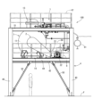
- FIG. 1 is a schematic front view showing an embodiment of an organic waste treatment device. It is a schematic back view showing the same embodiment. It is a schematic right view which shows the same embodiment. It is a schematic left side view showing the same embodiment.
- FIG. 3 is a schematic plan view showing the same embodiment. It is a schematic bottom view showing the same embodiment. It is a schematic front view which expands and shows the reaction container of the same embodiment.
- FIG. 3 is a schematic rear view showing an enlarged view of the reaction container of the same embodiment.
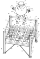
- FIG. 2 is an exploded rear perspective view for explaining a configuration in which a reaction container is placed on a pedestal.
- FIG. 3 is a rear perspective view showing the piping section together with the upper part of the pedestal.
- FIG. 7 is an exploded rear perspective view for explaining a configuration in which a reaction container is placed on a pedestal in another embodiment. It is a front view which expands and shows the lower part of the container main body of the same embodiment. It is a typical side view showing the container upper part of other embodiments.
- FIG. 1 to 6 are a schematic front view, rear view, right side view, left side view, top view, and bottom view showing one embodiment of an organic waste treatment apparatus.
- 7 to 10 are a schematic front view, rear view, right side view, and left side view showing the pedestal in cross section and the reaction container 1 enlarged.
- the organic waste treatment apparatus 100 includes a reaction container 1 that accommodates a material to be treated, a discharge side opening/closing lid 141 that opens and closes a discharge side opening 114 provided at the bottom of the container body 11 of the reaction container 1, and a reaction container 1. It is equipped with a stirring device 2 for stirring the processed material in 1.
- the organic waste treatment apparatus 100 charges a material to be treated, such as organic waste, into a sealable reaction container 1, and then converts the inside of the reaction container 1 into high-temperature, high-pressure saturated steam extracted from a steam extraction pipe 12. The mixture is brought into a subcritical state, and the treated material is hydrolyzed while being stirred by the stirring device 2.
- the treated product is taken out from the discharge side opening 114 provided at the bottom of the reaction vessel 1.
- the container body 11 of the reaction container 1 is made of, for example, stainless steel, is formed into a substantially spherical shape, and is capable of accommodating the processed material.
- the container internal space 111 (see FIGS. 11 and 12) of the container body 11 is approximately spherical.
- the reaction vessel 1 is made of metal such as stainless steel, and has a pressure resistance of, for example, up to about 5 MPa (megapascals).
- the reaction container 1 is installed on a pedestal 4.
- the input unit 13 includes an input tube 131 with upper and lower openings connected to a circular input port 112 opened at the top of the container body 11, and an opening/closing lid 132 on the input side that sealably closes the upper end of the input tube 131. There is.
- a discharge part 14 is provided at the bottom of the container body 11 to allow the processed product to be taken out from the container internal space 111.
- the discharge section 14 includes a discharge side opening/closing lid 141 that sealably closes a circular discharge side opening 114 opened at the bottom of the container body 11. Since the discharge side opening 114 is formed at the bottom top of the container body 11, the processed product can be discharged by gravity from the discharge port 148 (see FIGS. 11 and 12) provided in the discharge side opening 114. ing.
- a steam extraction pipe 12 is connected to the upper part of the container body 11 for injecting high-temperature, high-pressure saturated steam into the container internal space 111.
- a steam discharge pipe 15, a safety valve connection pipe 16, an air discharge pipe 17, a pressure gauge connection pipe 18, and a thermometer connection pipe 19 are connected to the side surface of the charging cylinder 131 of the reaction vessel 1.
- Pipes provided in the piping section 7 are connected to the pipes 12, 15, 16, and 17.
- a pressure gauge (not shown) for measuring the pressure in the container internal space 111 is connected to the pressure gauge connecting pipe 18 .
- a thermometer (not shown) for measuring the temperature of the internal space 111 of the container is connected to the thermometer connection pipe 19 .
- the stirring device 2 includes a rotating shaft 21 that horizontally passes through the container body 11, a prime mover 22 for rotating the rotating shaft 21, and a power transmission mechanism 23 that transmits the power of the prime mover 22 to the rotating shaft 21. .
- a stirring blade 25 is attached to the rotating shaft 21 via an arm 24. The stirring device 2 rotates the stirring blades 25 around the rotating shaft 21 within the container internal space 111 to stir the processed material contained in the container internal space 111 .
- FIG. 11 is an enlarged front sectional view showing the lower part of the reaction vessel 1 and the pedestal 4.
- FIG. 12 is a perspective view showing the lower part of the container body 11 in cross section, as seen diagonally from the rear left. The configuration of the discharge section 14 will be described with reference to FIGS. 11 and 12.
- the reaction container 1 is provided with the opening/closing lid 141 that opens and closes the discharge side opening 114 provided at the bottom of the container body 11.
- the opening/closing lid 141 is a sealed lid called a clutch door, and includes a substantially cylindrical lid main body 142 attached to the discharge side opening 114, a lid body 144 having a lid protrusion 143 that fits into the lid main body 142, and a lid. It includes a ring body 145 that connects the main body 142 and the lid body 144.
- the lid body 142, the lid body 144, and the ring body 145 are made of metal.
- the lid body 142 has a substantially cylindrical shape and is fixed to the container body 11 by welding or the like so as to protrude to the outside of the container body 11.
- the upper end of the lid body 142 fits into the discharge side opening 114.
- the inner circumferential surface 142b of the lid main body 142 is formed in a tapered shape that is narrower on the container inner space 111 side.
- the opening of the lid body 142 communicates the inside and outside of the container body 11 and forms a discharge port 148.
- the lid body 144 has a substantially truncated conical lid convex portion 143 that fits into the lid body 142, and a generally disc-shaped flange portion 146 that has a larger diameter than the lid convex portion 143.
- the outer peripheral surface 143b of the lid protrusion 143 is formed in a tapered shape along the inner peripheral surface 142b of the lid main body 142.
- the ring body 145 has a substantially cylindrical shape with an inner diameter larger than the outer diameter of the lid body 142 and the lid body 144.
- the ring body 145 has a plurality of body-side protrusions 145a that protrude inwardly from the upper end of its inner circumferential surface, and a plurality of lid-side protrusions 145b that protrude inwardly from the lower end of its inner circumferential surface. .
- a plurality of main body protrusions 142c protrude outward from the lower end of the outer peripheral surface of the lid body 142, and a plurality of lid bodies protrude from the outer peripheral surface of the brim portion 146 of the lid body 144.
- the protrusion 146a is sandwiched between the protrusions 145a and 145b of the ring body 145.
- the ring body 145 When opening the lid 141, the ring body 145 is rotated to position the lid protrusion 145b between the adjacent lid protrusions 146a of the lid 144. Thereby, the lid body 144 can be pulled out from the ring body 145.
- the lid 144 is connected to the lower outer peripheral surface of the container body 11 via a hinge member 147 having a substantially horizontal rotation axis 147a. Since the outer circumferential surface 143b of the lid protrusion 143 is formed in a tapered shape that is narrow on the side of the container internal space 111, it can be rotated around the rotation axis 147a of the hinge member 147 and fitted into the lid main body 142. . Therefore, the opening/closing mechanism of the lid body 144 can be formed with a simple structure of the hinge member 147, and the manufacturing cost of the opening/closing lid 141 can be reduced.
- the opening/closing mechanism of the lid body 144 is not limited to the hinge member, and for example, after pulling out the lid convex portion 143 straight along the center axis of the lid body 142 and the ring body 145, the opening/closing mechanism of the lid body 144 is moved outside the lower position of the discharge port 148. It may also be configured to be moved. In this case, the inner circumferential surface 142b of the lid body 142 and the outer circumferential surface 143b of the lid protrusion 143 may be parallel to the central axis of the lid body 142 instead of being tapered.
- the lid upper surface portion 141a of the opening/closing lid 141 closes the discharge side opening 114 and is exposed to the container internal space 111.
- the lid upper surface portion 141a is formed by a main body upper surface portion 142a of the lid main body 142 and a convex portion upper surface portion 143a of the lid convex portion 143.
- the lid upper surface portion 141a is disposed close to the discharge side opening 114. Thereby, it is possible to eliminate a space around the discharge side opening 114 in which the processed material remains when the stirring device 2 stirs the processed material, and it is possible to reduce the amount of unprocessed processed material.
- no step is formed between the outer peripheral edge of the lid top surface portion 141a (here, the upper end of the lid main body 142) and the opening upper end of the discharge side opening 114.
- no step is formed between the inner peripheral edge of the lid top surface 141a and the outer peripheral edge of the convex top surface 143a. Thereby, it is possible to reliably eliminate a space in which the processed material remains during agitation.
- the lid upper surface portion 141a is curved in a substantially concave spherical shape along the substantially concave spherical inner wall surface 11a of the container around the discharge side opening 114. This prevents contact between the stirring blade 25 and the lid top surface 141a even if the stirring blade 25 passing over the lid top surface 141a is rotated close to the container inner wall surface 11a of the container body 11 when the stirring device 2 is driven. It is possible to improve the stirring efficiency.
- the lid upper surface portion 141a may be located above (towards the center of the container body 11) with respect to the spherical shape of the container inner wall surface 11a to the extent that rotation of the stirring blade 25 is not inhibited.
- the lid upper surface portion 141a may be formed along a spherical shape having a larger diameter than the spherical shape of the inner wall surface 11a of the container.
- the lid upper surface portion 141a may be located on the lower side (the side away from the center of the container body 11) with respect to the spherical shape of the container inner wall surface 11a to such an extent that the material to be processed does not remain during stirring. do not have.
- the lid upper surface portion 141a may be formed along a spherical shape having a smaller diameter than the spherical shape of the inner wall surface 11a of the container, so that the lid upper surface portion 141a may be located below the spherical shape of the inner wall surface 11a of the container.
- the outer peripheral edge of the lid top surface 141a is located slightly below the opening top end of the discharge side opening 114, so that the processed material does not remain between the lid top surface 141a and the inner wall surface 11a of the container during stirring. There is no problem even if there is a level difference formed.
- the step can be used, for example, as a welding margin.
- the container body 11 and the lid body 142 may be integrally molded.
- the upper end surface of the lid body 142 having the same inner diameter as the opening diameter of the discharge side opening 114 is arranged to face the outer wall of the container body 11 around the discharge side opening 114, and the upper end surface of the convex portion of the lid body 144
- the structure may be such that the portion 143a closes the entire opening of the discharge side opening 114.
- the discharge side opening 114 constitutes the discharge port
- the lid upper surface portion 141a is constituted only by the convex upper surface portion 143a.
- the concave shape of the lid upper surface portion 141a does not have to be a substantially concave spherical shape as long as it is a concave shape that the stirring blade 25 does not come into contact with.
- the lid upper surface portion 141a of the opening/closing lid 141 can be curved in a concave shape along the inner wall surface of the container main body 11.
- FIG. 13 is a rear perspective view illustrating a configuration in which the reaction container 1 is placed on the pedestal 4.
- FIG. 14 is a rear perspective view showing the piping section 7 together with the upper part of the pedestal 4. As shown in FIG. The pedestal 4 will be explained with reference to FIGS. 12 and 13.
- the pedestal 4 includes four pillars 40 erected on the device installation surface F.
- Each of the four pillars 40 is formed of an H-shaped steel whose strong axis runs along the left-right direction, and is arranged at a corner of a rectangle along the front-rear, left-right direction.
- a first beam member 41 extending in the left-right direction is horizontally suspended between the middle parts of the columns 40 arranged on the left and right.
- a pair of left and right second beam members 42 extending in the front-rear direction are horizontally suspended between the middle portions of the front and rear first beam members 41 with an interval left and right.
- a pair of front and rear third beam members 43 extending in the left-right direction are horizontally suspended with an interval in the front-rear direction.
- the beam members 41, 42, and 43 are made of H-shaped steel having the same size (cross-sectional area) as the support column 40.
- a fourth beam member 44 extending in the front-rear direction is horizontally suspended between the middle parts of the pillars 40 arranged in front and rear.
- the fourth beam member 44 is made of H-beam steel having a smaller size than the support column 40.
- a brace 50 is provided on both left and right side surfaces and the back surface of the pedestal 4 to connect the lower part of the support 40 and the middle part of the first beam member 41 or the fourth beam member 44 .
- the brace 50 is made of L-shaped angle steel. No brace is provided on the front surface of the pedestal 4, so that a worker working on the device installation surface F can easily enter and exit the pedestal 4 from the front.
- a fifth beam member 45 forming a flint beam is provided at each of the four corners of the quadrangle surrounded by the second beam member 42 and the third beam member 43.
- a pair of front and rear sixth beam members 46 extending in the left-right direction on the left-right extension of the third beam member 43 are horizontally suspended with an interval in the front-rear direction.
- a seventh beam member 47 extending in the front-rear direction extends horizontally between the two.
- the beam members 45, 46, and 47 are made of H-beam steel smaller in size than the fourth beam member 44.
- An eighth beam member 48 extending in the front-rear direction is horizontally suspended between the front and rear sixth beam members 46 .
- the eighth beam member 48 is made of C-shaped steel (channel steel) smaller in size than the beam members 45, 46, and 47.
- a ninth beam member 49 extending in the left-right direction is horizontally suspended between the three seventh beam members 47 on the rear side and the beam members 42, 44.
- the ninth beam member 49 also extends horizontally between the first beam member 41 and the sixth beam member 46 on the front side.
- the ninth beam member 49 is made of L-shaped angle steel smaller in size than the eighth beam member 48.
- the reaction container 1 is placed at the intersection of the second beam member 42 and the third beam member 43.
- the reaction container 1 includes four metal support legs 20 provided at equal intervals in the circumferential direction at the lower part of the outer peripheral surface of the container body 11.
- a metal plate-shaped container mounting table 61 disposed across the second beam member 42, the third beam member 43, and the fifth beam member 45. It's stuck.
- the support legs 20 of the reaction container 1 are placed on a container mounting table 61 via a load cell 62.
- the pedestal 4 receives the load of the reaction vessel 1 with the support 40 and beam members 41, 42, 43 made of relatively large steel. Furthermore, a fifth beam member 45 constituting a flint beam is provided at the place where the reaction container 1 is placed, and the reaction container 1 is placed on a container mounting stand 61 fixed to the beam members 42, 42, 45. It makes it possible. Thereby, the pedestal 4 can ensure the strength to support the reaction vessel 1 even if the sizes of the other beam members 44, 46 to 49 are made relatively small, and the weight and manufacturing cost of the pedestal 4 can be reduced.
- the organic waste treatment apparatus 100 of this embodiment includes a load cell 62 between the support leg 20 of the reaction container 1 and the container mounting table 61 of the pedestal 4.
- the load cell 62 can be used to measure the weight of the processed material contained in the reaction vessel 1. If the weight of the material to be treated stored in the reaction container 1 is known before starting the treatment, for example, water can be added to the reaction container 1 to adjust the moisture content to an appropriate level before starting the treatment, depending on the moisture content of the material to be treated. Processing efficiency can be improved by doing the following.
- each of the four support legs 20 of the reaction container 1 is placed on the load cell 62, and as shown in FIGS. 15 and 16, the discharge part 14 is surrounded between the four support legs 20 and the load cell 62.
- One frame-shaped metal plate member 68 may be interposed. According to such a configuration, the frame-shaped metal plate member 68 disperses the load of the reaction vessel 1, so that it is possible to prevent the load from concentrating on one load cell 62, and to reduce the weight of the processed material accommodated in the reaction vessel 1. Measurement accuracy can be improved. Moreover, the heat transmitted from the support legs 20 of the reaction vessel 1 to the load cell 62 during processing can be dissipated by the frame-shaped metal plate member 68, and damage to the load cell 62 due to heat can be prevented.
- the shape of the frame-shaped metal plate member 68 is not limited to a rectangular frame shape, but may be any frame shape that can be disposed over each load cell 62 while positioning the discharge port 148 within the frame.
- the frame-shaped metal plate member 68 may have a donut shape (annular shape).
- the gap between the container body 11 and the beam members 42, 43, 45 becomes larger. This makes it easier for the air around the reaction vessel 1 to flow during processing, improving the ability to cool the lower part of the vessel body 11 and the load cell 62, and preventing damage to the load cell 62 due to heat.
- a first floor plate material 63 made of metal is laid on the beam members 41 to 49, except for the placement part of the reaction vessel 1.
- a plurality of first safety fences 64 are erected on the first beam member 41 and the fourth beam member 44 along the first beam member 41 or the fourth beam member 44 .
- a first upper beam member 51 extending in the front-rear direction or left-right direction is installed between the upper end portions of the adjacent columns 40.
- the first upper beam member 51 is made of H-shaped steel having the same size as the fourth beam member 44.
- a metal upper end plate 65 is joined to the upper end of the column 40.
- the second upper beam members 52 extending in the front-rear direction are horizontally suspended between the front and rear first upper beam members 51.
- the four second upper beam members 52 are arranged at intervals in the left-right direction, and the charging part 13 of the reaction vessel 1 is arranged between the two second upper beam members 52 closer to the center in the left-right direction. has been done.
- the second upper beam member 52 is made of C-shaped steel, which is smaller in size than the seventh beam member 47 and larger in size than the eighth beam member 48.
- a plurality of third upper beam members 53 are horizontally supported at intervals in the front and rear direction. ing.
- a second floor board material 66 made of metal is laid on top of the upper beam members 51 to 53.
- a plurality of second safety fences 67 are erected on the upper beam members 51 and 52 along the upper beam members 51 and 52.
- two third upper beam members 53 are provided between the two second upper beam members 52 closer to the left and right center, sandwiching the input portion 13 of the reaction vessel 1 in the front and back. It is being The rear of the input section 13 is an area where the piping section 7 is arranged. While the second floorboard material 66 is laid around the input section 13, the second floorboard material 66 is not laid in the area where the piping section 7 is provided.
- the upper beam members 52 and 53 are located at a position higher than the steam inlet pipe 12 of the reaction vessel 1 and higher than the steam exhaust pipe 15, the safety valve connection pipe 16, the air discharge pipe 17, the pressure gauge connection pipe 18, and the thermometer connection pipe 19. It is installed in a low position.
- the steam inlet pipe 12 can be accessed from the second floor of the pedestal 4 (above the first floor board 63), and the pipes 16 to 19 can be accessed from the third floor (above the second floor board 66). .
- the organic waste treatment apparatus 100 has a steam extraction system and a discharge system of the piping section 7 arranged vertically.
- the opening/closing lid 132 on the input side of the input section 13 of the reaction vessel 1 can be accessed from the third floor (above the second floor plate material 66), and the opening/closing lid 141 of the discharge section 14 can be accessed from the first floor (on the device installation surface). It is accessible from F).
- the steam extraction piping section 71 connected to the steam extraction pipe 12 is arranged to extend rearward from the steam extraction pipe 12 in the front-rear direction.
- a pipe end of the steam extraction piping section 71 is disposed at the rear of the pedestal 4 and connected to a steam supply pipe 82 extending from a steam header 81 .
- the steam header 81 stores steam supplied from a boiler (not shown).
- An inlet side on-off valve 711, an inlet flow rate adjustment valve 712, an inlet separator 713, and a steam check valve 714 are provided in the middle of the steam inlet piping section 71 in this order from the rear side.
- the valves 711 and 712 may be automatically controllable or may be configured to be manually controlled.
- the inlet side separator 713 removes water droplets contained in the steam. The removed water droplets are discharged through a steam water droplet drain pipe 715 that extends rearward from the lower part of the inlet side separator 713 along the front-rear direction.
- a check valve 716 is provided in the middle of the steam water droplet drain pipe 715.
- the air discharge piping section 72 connected to the air discharge pipe 17 is arranged to extend rearward from the air discharge pipe 17 in the front-rear direction.
- An inlet strainer 721, a steam trap 722, and the like are provided in the middle of the air exhaust pipe 72 in this order from the air exhaust pipe 17 side.
- the air exhaust piping section 72 removes solid components and water droplets contained in the gas discharged from the air exhaust pipe 17 when steam is extracted from the steam extraction pipe 12 into the container internal space 111 through an extraction side strainer 721 and a steam trap. 722 to remove and discharge.
- the water droplets removed by the steam trap 722 are discharged through an air drain pipe 723 that extends rearward from the bottom of the steam trap 722 along the front-rear direction.
- the safety valve piping section 73 connected to the safety valve connection pipe 16 is arranged to extend rearward from the safety valve connection pipe 16 in the front-rear direction.
- the safety valve piping section 73 is equipped with a safety valve 731 in the middle thereof, and when the internal space 111 of the container rises above a set pressure during processing, the safety valve 731 is activated to release steam in the internal space 111 of the container to reduce the pressure. It has become.
- the steam exhaust pipe 15 is provided on the left side of the input tube 131 at the top of the reaction vessel 1.
- the steam exhaust pipe section 74 connected to the steam exhaust pipe 15 extends leftward, then extends rearward on the left side of the input tube 131 via the downward U-shaped solids trap 741, and then bends rightward to input the solids. It is guided to the rear of the tube 131. Further, the steam exhaust pipe section 74 is arranged to extend in the front-rear direction from a position near the charging tube 131 toward the rear.
- the downward U-shaped solid trap 741 can remove relatively large solids from the exhaust steam, and is accessible from the second floor of the pedestal 4 (above the first floor plate material 63).
- the solid matter accumulated in the solid matter trap 741 can be removed by removing a blank flange provided at the bottom of the solid matter trap 741.
- blind flanges may be provided at two locations on the left and right sides of the bottom of the solid trap 741. By doing this, when removing solids etc. accumulated in the solid trap 741, remove both the left and right blind flanges, insert the jig into the solid trap 741 from one opening, and open the other. Since solid objects etc. can be pushed out from the opening, maintenance efficiency is improved.
- the solid trap 741 may be disposed behind the input tube 131.
- the steam exhaust pipe section 74 branches from the rear of the charging tube 131 into a main exhaust pipe section 742 and an emergency exhaust pipe section 747.
- the main discharge pipe section 742 and the emergency discharge pipe section 747 are both arranged to extend in the front-rear direction.
- a vacuum pump suction mechanism
- the vacuum pump may be connected to the steam exhaust pipe section 74, and the vacuum pump may be used to reduce the pressure in the container internal space 111 after inputting the material to be treated and before steam extraction to improve the extraction efficiency. do not have.
- the discharge side on-off valve 744 which will be described later, is opened to proceed with steam discharge, and when the pressure in the container internal space 111 becomes almost equal to the outside pressure (for example, when the outside pressure becomes +0.02 MPa), the vacuum pump is turned on. Alternatively, the steam inside the container internal space 111 may be sucked to bring it closer to the outside pressure. Thereby, it is possible to minimize the sound of steam flowing out, steam, and odor that occur when opening the lid 132 at the end of the process.
- the vacuum pump may be automatically controllable or may be configured to be manually controlled.
- the main discharge pipe section 742 includes, in order from the upstream side of the exhaust flow, a discharge side strainer 743, a discharge side on-off valve 744, and a discharge flow rate adjustment valve 745.
- the exhaust side strainer 743 removes relatively small solids contained in the exhaust steam.
- the valves 744 and 745 may be automatically controllable or may be configured to be manually controlled.
- a condenser 746 that converts vapor into liquid is connected downstream of the exhaust flow of the main exhaust pipe section 742 .
- the condenser 746 is provided vertically and vertically at the rear of the pedestal 4, and is accessible from the second floor (above the first floorboard material 63).
- a manual on-off valve 748 is provided in the middle of the emergency discharge pipe section 747. In an emergency when the internal space 111 of the container rises above a set pressure during processing and does not come down, the manual on-off valve 748 can be opened to release steam from the internal space 111 of the container to reduce the pressure.
- the pipes and parts of the piping section 7 can be supported by a portal frame installed on the second floor behind the reaction vessel 1.
- the gate-shaped frame can be erected on the left and right second beam members 42, which are relatively large in size. In this way, a robust portal frame can be formed, and the pipes and parts of the piping section 7 can be safely supported.
- the stirring device 2 includes a rotating shaft 21 that penetrates the container body 11 substantially horizontally, a prime mover 22 for rotating the rotating shaft 21, and a power transmission mechanism that transmits the power of the prime mover 22 to the rotating shaft 21. It is equipped with 23.
- a pair of left and right bearing pedestals 211 are fixed to the left and right side surfaces of the container body 11, protruding outward from the left and right. Both ends of the rotating shaft 21 are rotatably supported by bearings 212 provided on a bearing pedestal 211. Rotating shaft sprockets 213 are fixed to both ends of the rotating shaft 21 on the left and right sides of the bearing 212, respectively.
- the prime mover 22 is, for example, an electric motor with a speed reducer, and is placed on a prime mover support plate 221 fixed to the rear of the reaction vessel 1 across the second beam member 42 and the seventh beam member 47 of the pedestal 4. ing.
- a prime mover sprocket 223 is fixed to an output shaft 222 of the prime mover 22. Note that as the prime mover 22, it is also possible to employ other prime movers such as an internal combustion engine or a hydraulic motor.
- the power transmission mechanism 23 includes a transmission rotation shaft 231 provided between the prime mover 22 and the reaction vessel 1.
- the transmission rotation shaft 231 is arranged to extend in the left-right direction.
- a bearing stand 232 is fixed to each of the three seventh beam members 47 provided near the rear of the frame 4. Both left and right end portions and a center portion in the left and right direction of the transmission rotation shaft 231 are rotatably supported by a bearing 233 attached to a bearing stand 232 .
- a driven sprocket 234 is fixed to the transmission rotation shaft 231 in front of the prime mover sprocket 223.
- a drive chain 235 is wound between the prime mover sprocket 223 and the driven sprocket 234, so that the power of the prime mover 22 can be transmitted to the transmission rotation shaft 231.
- Sprockets 223, 234 and drive chain 235 are covered with cover 236.
- Both ends of the transmission rotation shaft 231 are arranged diagonally below and rearward of both ends of the rotation shaft 21.
- a transmission shaft sprocket 237 is fixed to each end of the transmission rotation shaft 231 .
- Left and right driven chains 238 are wound between the left and right rotating shaft sprockets 213 and the left and right transmission shaft sprockets 237.
- the stirring blades 25 may be rotated in the opposite direction by switching the prime mover 22 between normal rotation and reverse rotation during one process to perform efficient stirring.
- the rotation speed of the stirring blade 25 may be changed during one process to perform efficient stirring. For example, the rotation speed can be changed to "high speed,” “medium speed,” or "low speed.” You can configure it.
- the organic waste treatment apparatus 100 can be formed compactly. Moreover, if the empty spaces on both the left and right sides of the prime mover 22 on the second floor are effectively utilized as installation areas for the oil compressor 8 and the air compressor 9, a more compact organic waste treatment apparatus 100 can be realized.
- FIG. 17 is a schematic side view showing the upper part of a container according to another embodiment.
- an input pipe 91 for inputting liquid waste is connected to the reaction container 1.
- This embodiment is configured such that liquid waste can be introduced into the reaction vessel 1 from the input pipe 91 without opening or closing the opening/closing lid 132 on the input side.
- the charging pipe 91 is connected to the side surface of the charging cylinder 131.
- the end of the input pipe 91 on the opposite side from the reaction vessel 1 is connected to a tank 92 that stores liquid waste.
- the liquid waste stored in the tank 92 is, for example, a slurry liquid such as pig dung or sludge.
- a first input on-off valve 93 and a second input on-off valve 94 are provided in series.
- a washing water pipe 95 is connected to a midway portion of the input pipe 91 between the first input on-off valve 93 and the second input on-off valve 94.
- the end of the wash water pipe 95 opposite to the input pipe 91 is connected to a wash water supply section 96 that supplies wash water.
- a wash water on-off valve 97 is provided in the middle of the wash water pipe 95.
- liquid waste can be charged into the reaction vessel 1 from the charging pipe 91 with the opening/closing lid 132 on the charging side closed. Therefore, it is possible to prevent the bad odor emitted from the liquid waste from spreading around the reaction vessel 1, thereby improving the working environment.
- a deodorizing device may be connected to the middle of the steam exhaust pipe section 74 to prevent the discharge of bad odors.
- the first input on-off valve 93 is opened, the second input on-off valve 94 is closed, and the wash water on-off valve 97 is opened to wash the wash water.
- a portion of the input tube 91 close to the reaction container 1 is inclined diagonally downward toward the reaction container 1. This makes it difficult for liquid waste to remain inside the portion of the input tube 91 that is close to the reaction vessel 1.
- the first input on-off valve 93 is closed. Since high pressure during processing is not applied to the second input on-off valve 94 and the wash water on-off valve 97, cheaper on-off valves can be selected compared to the first input on-off valve 93, which can reduce manufacturing costs.
- the input tube 91 is connected to the input cylinder 131 of the reaction container 1, but it may be connected to the upper part of the container body 11. Further, a pump for feeding liquid waste from the tank 92 toward the reaction container 1 may be provided in the middle of the input pipe 91.
- the bearing 212 that rotatably supports the rotating shaft 21 may be supported by providing a bearing support frame on the pedestal 4.
- the size of the beam member on which the bearing support frame is erected in the pedestal 4 may be increased to increase the support rigidity of the bearing 212.
- a load cell is interposed between the bearing support frame and the beam member, and the load cell and the load cell 62 below the support leg 20 of the container body 11 are configured to be able to measure the weight of the processed material put into the container internal space 111. You may.
- a plate-shaped member covering these load cells is interposed between the bearing support frame and the load cell below it, and between the support leg 20 and the load cell 62 to distribute the load of the reaction vessel 1.
- the load cells may be distributed over these load cells.
- two organic waste treatment apparatuses 100 may be arranged side by side on the left and right, and the steam header 81 may be shared by these organic waste treatment apparatuses 100.
- the steam exhaust pipe 15 may be connected to the input cylinder 131.
- at least one of the safety valve connection pipe 16, the air discharge pipe 17, the pressure gauge connection pipe 18, and the thermometer connection pipe 19 may be connected to the container body 11.
- the organic waste treatment apparatus of the embodiment includes a reaction container 1 that accommodates the processed material and is provided with a discharge port 148 at the bottom, a pedestal 4 that supports the reaction container 1, It is equipped with
- the pedestal 4 includes four pillars 40 erected at the corners of a rectangle in plan view on the device installation surface, and a pair of first beams horizontally suspended between the pillars 40 aligned in a first direction along one side of the rectangle.
- a fifth beam member 45 provided in each section is provided.
- the fifth beam member 45 forms a flint beam member.
- the support column 40 and beam members 41, 42, 43, and 45 are made of steel.
- the reaction vessel 1 is configured such that the second beam member 42 and the third beam member 43 are connected to each other while the discharge port 148 is located at the intersection of the second beam member 42 and the third beam member 43 within the rectangular frame in plan view. It is placed astride the fifth beam member 45.
- the load of the reaction vessel 1 is received by the support 40 formed of steel and the first to third beam members 41 to 43, and the fifth Since the beam member 45 (flint beam member) is provided, the support rigidity of the reaction vessel 1 can be improved.
- the size of the other beam members for example, the fourth beam member 44, the sixth to ninth beam members 46 to 49 shown in FIGS. 1 to 13
- the response The strength to support the container 1 can be ensured, and the weight and manufacturing cost of the pedestal 4 can be reduced.
- the fifth beam member 45 (flint beam member) is made of a steel material with a smaller cross-sectional area than the first to third beam members 41 to 43.
- the weight and manufacturing cost of the frame can be further reduced.
- a metal container mounting table 61 which is disposed at the base of the container, is firmly fixed.
- the reaction container 1 is placed on a container mounting table 61.
- the reaction container mounting portion of the pedestal 4 can be made to have a more robust structure, so the reaction container 1 can be reliably supported and safety can be improved.
- the pedestal 4 includes a pair of fourth beam members 44 that are horizontally suspended between the pillars arranged in the second direction.
- the fourth beam member 44 is provided extending in the second direction.
- the lower part of the support 40 and the middle part of the first or fourth beam member 41 or 44 are attached to three outer peripheral sides of the four outer peripheral sides surrounded by the support 40 and the first and fourth beam members 41 and 44.
- a connecting brace 50 is provided.
- the rigidity and strength of the pedestal 4 can be improved, and by not providing the brace 50 on one of the four outer periphery surfaces, an operator can 4 can be easily accessed and exited, improving work efficiency.
- the reaction container 1 is supported on the pedestal 4 via a load cell 62.
- the weight of the material to be treated stored in the reaction vessel 1 can be measured, so that the processing time and temperature can be adjusted according to the weight of the material to be treated, the moisture content measured in advance, etc. Processing efficiency can be improved by adding .
- a frame-shaped metal plate member 68 (frame-shaped metal member) may be interposed between the reaction container 1 and the load cell 62, which surrounds the discharge port 148 in plan view.
- the frame-shaped metal plate member 68 disperses the load of the reaction vessel 1, so that it is possible to prevent the load from concentrating on one load cell 62, and the weight of the processed material accommodated in the reaction vessel 1 can be prevented.
- the measurement accuracy can be improved.
- the heat transmitted from the reaction vessel 1 to the load cell 62 during processing can be dissipated by the frame-shaped metal plate member 68, and damage to the load cell 62 due to heat can be prevented.
- the organic waste treatment apparatus of the embodiment includes an input port 112 at the top and a discharge port 148 at the bottom to accommodate the reactor.
- a container 1 is provided.
- the reaction container 1 includes a charging cylinder 131 with vertical openings connected upward to a charging port 112 opened at the top of the container body 11, and an opening/closing lid 132 on the charging side that sealably closes the upper end of the charging cylinder 131.
- a steam extraction pipe 12 for extracting saturated steam into the interior space 111 of the container is connected to the upper part of the container body 11 .
- a steam exhaust pipe 15, a safety valve connection pipe 16, and an air exhaust pipe 17 are connected to the side surface of the charging cylinder 131.
- the steam extraction system piping and the exhaust system piping into the reaction vessel 1 can be arranged vertically, and the extraction system piping and the exhaust system piping can be arranged vertically. This reduces the chance of misunderstanding the piping and improves maintainability.
- the pipes extending from the steam extraction pipe 12, the steam discharge pipe 15, the safety valve connection pipe 16, and the air discharge pipe 17 are reacted.
- a piping section 7 extending from a position near the container 1 in the same direction is provided.
- the piping system can be arranged all at once, resulting in good maintainability.
- the organic waste treatment apparatus of the embodiment includes a pedestal 4 that supports the reaction container 1.
- the pedestal 4 includes a first floor board material 63 (first floor section) provided at a height position below the reaction container 1, and a second floor board material 66 (second floor section) provided at a height position above the reaction container 1. Department). Piping constituting the piping section 7 extends along the second floor plate material 66 (second floor).
- each pipe can be accessed from both the first floor section and the second floor section, thereby improving maintainability.
- the organic waste treatment apparatus of the embodiment includes a stirring device 2 that stirs the treated material in the reaction vessel 1.
- the drive source (prime mover 22 and power transmission mechanism 23) of the stirring device 2 is installed below the piping section 7 and above the first floor plate material 63 (first floor section).
- the empty space in the first floor section below the piping section 7 can be effectively utilized, so that the organic waste treatment apparatus can be formed compactly.
Landscapes
- Chemical & Material Sciences (AREA)
- Chemical Kinetics & Catalysis (AREA)
- Engineering & Computer Science (AREA)
- Environmental & Geological Engineering (AREA)
- Water Supply & Treatment (AREA)
- Hydrology & Water Resources (AREA)
- Life Sciences & Earth Sciences (AREA)
- Organic Chemistry (AREA)
- Processing Of Solid Wastes (AREA)
- Treatment Of Sludge (AREA)
- Mixers With Rotating Receptacles And Mixers With Vibration Mechanisms (AREA)
- Accessories For Mixers (AREA)
- Mixers Of The Rotary Stirring Type (AREA)
Priority Applications (7)
| Application Number | Priority Date | Filing Date | Title |
|---|---|---|---|
| CN202511953392.8A CN121847568A (zh) | 2022-04-20 | 2023-04-12 | 有机性废弃物处理装置 |
| CN202511953366.5A CN121847566A (zh) | 2022-04-20 | 2023-04-12 | 有机性废弃物处理装置 |
| KR1020237030611A KR20230150305A (ko) | 2022-04-20 | 2023-04-12 | 유기성 폐기물 처리 장치 |
| CN202380010807.0A CN117279867B (zh) | 2022-04-20 | 2023-04-12 | 有机性废弃物处理装置 |
| JP2023551159A JP7449628B1 (ja) | 2022-04-20 | 2023-04-12 | 有機性廃棄物処理装置 |
| CN202511953381.XA CN121847567A (zh) | 2022-04-20 | 2023-04-12 | 有机性废弃物处理装置 |
| JP2024026180A JP2024052832A (ja) | 2022-04-20 | 2024-02-26 | 有機性廃棄物処理装置 |
Applications Claiming Priority (2)
| Application Number | Priority Date | Filing Date | Title |
|---|---|---|---|
| JP2022-069416 | 2022-04-20 | ||
| JP2022069416 | 2022-04-20 |
Publications (1)
| Publication Number | Publication Date |
|---|---|
| WO2023204118A1 true WO2023204118A1 (ja) | 2023-10-26 |
Family
ID=88419997
Family Applications (1)
| Application Number | Title | Priority Date | Filing Date |
|---|---|---|---|
| PCT/JP2023/014823 Ceased WO2023204118A1 (ja) | 2022-04-20 | 2023-04-12 | 有機性廃棄物処理装置 |
Country Status (4)
| Country | Link |
|---|---|
| JP (2) | JP7449628B1 (https=) |
| KR (1) | KR20230150305A (https=) |
| CN (4) | CN121847567A (https=) |
| WO (1) | WO2023204118A1 (https=) |
Citations (4)
| Publication number | Priority date | Publication date | Assignee | Title |
|---|---|---|---|---|
| JP2002370079A (ja) * | 2001-04-09 | 2002-12-24 | Japan Engineering Supply:Kk | 生ゴミ処理機 |
| JP3130553U (ja) * | 2007-01-18 | 2007-03-29 | 株式会社クラフトマン | 減容分解装置 |
| WO2019073673A1 (ja) * | 2017-10-11 | 2019-04-18 | TakedaWorks株式会社 | 撹拌装置およびそれを用いた有機廃棄物の処理方法 |
| JP2021169074A (ja) * | 2020-04-17 | 2021-10-28 | 日本有機物リサイクルプラント株式会社 | 亜臨界水処理装置 |
Family Cites Families (15)
| Publication number | Priority date | Publication date | Assignee | Title |
|---|---|---|---|---|
| JP2002306942A (ja) * | 2001-04-11 | 2002-10-22 | Earth Clean Kk | 地球釜 |
| JP2003088830A (ja) * | 2001-09-19 | 2003-03-25 | Aichi Electric Co Ltd | 廃棄物処理装置 |
| JP2003154335A (ja) * | 2001-11-26 | 2003-05-27 | Aichi Electric Co Ltd | 廃棄物処理装置 |
| JP2004130235A (ja) * | 2002-10-10 | 2004-04-30 | Tagami Toyomi | 廃棄物の減容装置および減容方法 |
| JP4644444B2 (ja) * | 2004-06-04 | 2011-03-02 | 賢三 高橋 | 感染性廃棄物用熱分解炉及び感染性廃棄物処理装置 |
| EP3210680B1 (en) * | 2005-05-27 | 2019-01-23 | Miyashiro, Tomonao | Apperatus for treatment of organic waste material and method for seperating and recovering liquid material |
| JP2008055285A (ja) | 2006-08-30 | 2008-03-13 | Fujimura Tsusho Kk | 水蒸気の水成分と水蒸気の熱にて被処理物を水熱処理する水熱処理装置と方法 |
| CN201774216U (zh) * | 2010-07-22 | 2011-03-23 | 全冠企业有限公司 | 对电缆与浪管双迫紧的防水固定头 |
| JP2016097322A (ja) * | 2014-11-18 | 2016-05-30 | トーヨーマクロ合同会社 | 有機性廃棄物処理装置及び有機性廃棄物の処理方法 |
| JP6377087B2 (ja) * | 2016-01-22 | 2018-08-22 | 株式会社ピーシーエス | 亜臨界水処理方法及び装置 |
| JP6303081B1 (ja) * | 2017-03-31 | 2018-03-28 | 政徳 石丸 | 有機性廃棄物処理装置 |
| JP6256961B1 (ja) * | 2017-04-28 | 2018-01-10 | 株式会社イープラン | 有機性廃棄物処理装置及び有機性廃棄物処理方法 |
| EP3983025A4 (en) * | 2019-06-13 | 2023-10-04 | Padcare Labs Private Limited | INTELLIGENT PORTABLE DEVICE AND SYSTEM FOR DISPOSAL OF SANITARY WASTE |
| KR102266029B1 (ko) * | 2019-07-16 | 2021-06-16 | 정세현 | 차량용 유기물 및 무기물 분해 장치 |
| BR102021013275B1 (pt) * | 2021-07-05 | 2022-01-18 | Eco Circuito Importação E Comercio De Equipamentos Ltda. - Epp | Equipamento de processamento de resíduos de alimentos e método de operação de equipamento de processamento de resíduos de alimentos |
-
2023
- 2023-04-12 WO PCT/JP2023/014823 patent/WO2023204118A1/ja not_active Ceased
- 2023-04-12 KR KR1020237030611A patent/KR20230150305A/ko active Pending
- 2023-04-12 CN CN202511953381.XA patent/CN121847567A/zh active Pending
- 2023-04-12 JP JP2023551159A patent/JP7449628B1/ja active Active
- 2023-04-12 CN CN202380010807.0A patent/CN117279867B/zh active Active
- 2023-04-12 CN CN202511953392.8A patent/CN121847568A/zh active Pending
- 2023-04-12 CN CN202511953366.5A patent/CN121847566A/zh active Pending
-
2024
- 2024-02-26 JP JP2024026180A patent/JP2024052832A/ja active Pending
Patent Citations (4)
| Publication number | Priority date | Publication date | Assignee | Title |
|---|---|---|---|---|
| JP2002370079A (ja) * | 2001-04-09 | 2002-12-24 | Japan Engineering Supply:Kk | 生ゴミ処理機 |
| JP3130553U (ja) * | 2007-01-18 | 2007-03-29 | 株式会社クラフトマン | 減容分解装置 |
| WO2019073673A1 (ja) * | 2017-10-11 | 2019-04-18 | TakedaWorks株式会社 | 撹拌装置およびそれを用いた有機廃棄物の処理方法 |
| JP2021169074A (ja) * | 2020-04-17 | 2021-10-28 | 日本有機物リサイクルプラント株式会社 | 亜臨界水処理装置 |
Also Published As
| Publication number | Publication date |
|---|---|
| CN121847567A (zh) | 2026-04-14 |
| KR20230150305A (ko) | 2023-10-30 |
| JP2024052832A (ja) | 2024-04-12 |
| CN117279867A (zh) | 2023-12-22 |
| JPWO2023204118A1 (https=) | 2023-10-26 |
| CN121847568A (zh) | 2026-04-14 |
| CN117279867B (zh) | 2026-01-13 |
| JP7449628B1 (ja) | 2024-03-14 |
| CN121847566A (zh) | 2026-04-14 |
Similar Documents
| Publication | Publication Date | Title |
|---|---|---|
| JP5026387B2 (ja) | 遠心分離装置 | |
| JP7449628B1 (ja) | 有機性廃棄物処理装置 | |
| CN108862631A (zh) | 一种基于微生物降解的防堵塞污水处理装置 | |
| JP3130553U (ja) | 減容分解装置 | |
| CN111841262A (zh) | 工业废气中voc的处置消除装置 | |
| KR20210065361A (ko) | 혐기성소화조의 교반기 | |
| CN220150498U (zh) | 一种双切碎模式的外置水泵污水提升设备 | |
| JP4638337B2 (ja) | 有機物処理機 | |
| KR20200063551A (ko) | 공기배출수단과 마이크로버블의 효율성이 향상된 자가보수가 용이한 오염수 정화장치 | |
| JP2742974B2 (ja) | 2段式スラリー処理方法及び装置 | |
| CN213803380U (zh) | 一种用于生活污水处理的生化池 | |
| CN207446949U (zh) | 一种生物安全实验室动物尸体无害化处理设备 | |
| JP2007130620A5 (https=) | ||
| CN224180615U (zh) | 一种农药生产装置 | |
| JP4671014B2 (ja) | 生ごみ処理装置 | |
| CN216236393U (zh) | 一种工业循环冷却水自动处理设备 | |
| CN215667657U (zh) | 一种出水口防堵塞的化粪池 | |
| CN212492263U (zh) | 一种多级涡旋水流式废气处理装置 | |
| CN223213965U (zh) | 一种催化氧化处理装置 | |
| CN216106385U (zh) | 一种大流量污水处理器 | |
| CN219580515U (zh) | 反应罐及其搅拌密封装置 | |
| CN223522345U (zh) | 一种水处理自动消毒装置 | |
| CN218392438U (zh) | 一种用于工业自动化的工业废水处理装置 | |
| CN209226721U (zh) | 一种新型工业环保设备 | |
| KR101682544B1 (ko) | 구조물 절단작업의 오염방지장치 |
Legal Events
| Date | Code | Title | Description |
|---|---|---|---|
| WWE | Wipo information: entry into national phase |
Ref document number: 2023551159 Country of ref document: JP |
|
| ENP | Entry into the national phase |
Ref document number: 20237030611 Country of ref document: KR Kind code of ref document: A |
|
| WWE | Wipo information: entry into national phase |
Ref document number: 202380010807.0 Country of ref document: CN |
|
| 121 | Ep: the epo has been informed by wipo that ep was designated in this application |
Ref document number: 23791766 Country of ref document: EP Kind code of ref document: A1 |
|
| NENP | Non-entry into the national phase |
Ref country code: DE |
|
| 122 | Ep: pct application non-entry in european phase |
Ref document number: 23791766 Country of ref document: EP Kind code of ref document: A1 |