WO2023204094A1 - バックルおよびこれを備えたシートベルト装置 - Google Patents
バックルおよびこれを備えたシートベルト装置 Download PDFInfo
- Publication number
- WO2023204094A1 WO2023204094A1 PCT/JP2023/014643 JP2023014643W WO2023204094A1 WO 2023204094 A1 WO2023204094 A1 WO 2023204094A1 JP 2023014643 W JP2023014643 W JP 2023014643W WO 2023204094 A1 WO2023204094 A1 WO 2023204094A1
- Authority
- WO
- WIPO (PCT)
- Prior art keywords
- harness
- buckle
- vehicle
- cover member
- bracket
- Prior art date
- Legal status (The legal status is an assumption and is not a legal conclusion. Google has not performed a legal analysis and makes no representation as to the accuracy of the status listed.)
- Ceased
Links
Images


Classifications
-
- A—HUMAN NECESSITIES
- A44—HABERDASHERY; JEWELLERY
- A44B—BUTTONS, PINS, BUCKLES, SLIDE FASTENERS, OR THE LIKE
- A44B11/00—Buckles; Similar fasteners for interconnecting straps or the like, e.g. for safety belts
- A44B11/25—Buckles; Similar fasteners for interconnecting straps or the like, e.g. for safety belts with two or more separable parts
- A44B11/2503—Safety buckles
- A44B11/2569—Safety measures
-
- B—PERFORMING OPERATIONS; TRANSPORTING
- B60—VEHICLES IN GENERAL
- B60R—VEHICLES, VEHICLE FITTINGS, OR VEHICLE PARTS, NOT OTHERWISE PROVIDED FOR
- B60R22/00—Safety belts or body harnesses in vehicles
- B60R22/18—Anchoring devices
- B60R22/26—Anchoring devices secured to the seat
-
- B—PERFORMING OPERATIONS; TRANSPORTING
- B60—VEHICLES IN GENERAL
- B60R—VEHICLES, VEHICLE FITTINGS, OR VEHICLE PARTS, NOT OTHERWISE PROVIDED FOR
- B60R22/00—Safety belts or body harnesses in vehicles
- B60R22/48—Control systems, alarms, or interlock systems, for the correct application of the belt or harness
-
- B—PERFORMING OPERATIONS; TRANSPORTING
- B60—VEHICLES IN GENERAL
- B60R—VEHICLES, VEHICLE FITTINGS, OR VEHICLE PARTS, NOT OTHERWISE PROVIDED FOR
- B60R22/00—Safety belts or body harnesses in vehicles
- B60R22/18—Anchoring devices
- B60R2022/1806—Anchoring devices for buckles
-
- B—PERFORMING OPERATIONS; TRANSPORTING
- B60—VEHICLES IN GENERAL
- B60R—VEHICLES, VEHICLE FITTINGS, OR VEHICLE PARTS, NOT OTHERWISE PROVIDED FOR
- B60R22/00—Safety belts or body harnesses in vehicles
- B60R22/48—Control systems, alarms, or interlock systems, for the correct application of the belt or harness
- B60R2022/4808—Sensing means arrangements therefor
- B60R2022/4816—Sensing means arrangements therefor for sensing locking of buckle
Definitions
- the present invention relates to a buckle and a seatbelt device equipped with the same.
- a vehicular seat belt device in which a buckle includes a switch for sensing the state of the device and a harness for transmitting a signal from the switch.
- switches include, for example, slide switches and hall effect switches that detect whether the seat belt tongue is attached to the buckle in question, and the harness uses signals detected by such switches to control the vehicle.
- the information is provided to be sent to a device (such as a CPU) (see, for example, Patent Documents 1 to 4).
- the present invention provides a buckle having a structure that simplifies the work for assembling the harness and improves the durability of the harness when the buckle swings, and a seat belt device equipped with the same.
- the purpose is to
- One aspect of the present invention is a buckle whose base end side is movably attached to a bracket constituting a seat belt device for a vehicle, the buckle comprising: A cover member that constitutes the wall of the buckle; a detection member disposed within the cover member and detecting whether the buckle is in a predetermined state; a harness that transmits the signal detected by the detection member to the vehicle; Guiding the harness while regulating the movable range of the harness within the cover member and providing play to the extent that at least a portion of the harness moves relative to the cover member when the buckle moves relative to the bracket.
- a harness holder It has a buckle.
- the buckle configured as described above has a harness holder that guides the harness, for example, multiple harnesses can be hung together on the harness holder and guided, all at once and easily. It is possible to have the harness crawl inside the buckle. Furthermore, since the harness holder also restricts the movable range of the harness within the cover member, it is easy to avoid a situation where the harness is accidentally caught when the cover member is assembled to the buckle, for example. In addition, in the buckle configured as described above, when the buckle moves relative to the bracket, the harness holder guides the harness while providing play to the extent that at least a portion of the harness moves relative to the cover member. Therefore, the durability of the harness can be improved when the buckle swings.
- the harness holder may have a guide portion that guides the harness from the proximal end to the distal end of the buckle toward the detection member midway.
- the guide portion may be provided only at a portion that guides the harness toward the detection member in the harness path from the bracket to the detection member.
- the guide portion as described above may be formed of a cylindrical surface or a curved surface similar to the cylindrical surface.
- the harness holder in the buckle as described above may have a fall prevention part that prevents the harness from falling off the guide part.
- the falling-off prevention part is formed in such a shape and size that the harness does not fall off from the guide part when the buckle moves relative to the bracket and the harness is in its most bent state. You can.
- the buckle described above may be movable relative to the bracket in the width direction of the vehicle.
- the buckle described above may further include a restraining portion that prevents the harness holder, which is detachable from the buckle, from lifting up.
- the buckle described above may be movable relative to the bracket in the longitudinal direction of the vehicle.
- the above buckle may further include a rotation prevention part that prevents the harness holder, which is detachable from the buckle, from rotating relative to the buckle in the longitudinal direction of the vehicle.
- At least a portion of the harness may be arranged approximately at the center of the width of the cover member in the longitudinal direction of the vehicle.
- the detection member is provided inside the cover member on both sides or one side in the longitudinal direction of the vehicle, and the harness is composed of multiple wires that branch halfway toward each of the detection members. may be configured.
- a seat belt device includes the buckle described above.
- a buckle having a structure capable of simplifying the work for assembling the harness and improving the durability of the harness when the buckle swings, and a seat belt device equipped with the same. be able to.
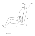
- FIG. 1 is a diagram schematically showing a buckle and a bracket of a seat belt device according to an embodiment of the present invention, as viewed from the left side of the seat.
- FIG. 3 is a left side view of the seat including a buckle and a bracket.
- FIG. 1B is a view of the buckle and bracket shown in FIG. 1A as viewed from the front of the seat.
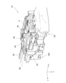
- FIG. 3 is a front view of the seat with buckles and brackets. It is a perspective view showing an example of the internal structure of a buckle. It is a perspective view seen from another angle showing an example of the internal structure of a buckle.
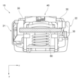
- FIG. 3 is a diagram showing an example of the internal structure of the buckle, viewed from the tip side.
- FIG. 3 is a diagram showing an example of the internal structure of the buckle, viewed from the proximal end side.
- FIG. 2 is a diagram showing an example of the internal structure of the buckle, seen from the front of the vehicle.
- FIG. 3 is a diagram showing the structure around the harness holder in a cross section perpendicular to the y-axis.
- FIG. 3 is a view of the frame portion to which the harness holder is attached, viewed from the back (the side opposite to the harness holder).
- FIG. 3 is a diagram showing the internal structure of the buckle in a cross section perpendicular to the x-axis.
- FIG. 3 is a diagram showing the structure around the harness holder inside the buckle.
- FIG. 6 is a diagram showing a state in which the buckle moves relative to the bracket in the longitudinal direction of the vehicle.
- up and down, left and right, and front and rear are defined as follows (see FIGS. 1B and 2B).
- the direction in which the occupant is facing is referred to as the front
- the opposite direction is referred to as the rear
- the front-rear direction is expressed as the x-axis.
- the right side of the occupant is referred to as the right direction
- the left side of the occupant is referred to as the left direction
- the left-right direction is expressed as the y-axis.
- the vehicle seat 100 may be a front seat (that is, a driver's seat or a passenger seat) or a rear seat.
- a seat belt device 1 for a vehicle has a seat belt 2 that is a webbing that restrains an occupant.
- the seat belt 2 includes a shoulder belt 2a extending from an upper guide loop or an upper anchor (not shown) to a tongue 2t, and a lap belt 2b extending from the tongue 2t to a lap anchor (not shown). (See Figures 1A-2B).
- the shoulder belt 2a is stretched diagonally from the upper part of one left and right side of the occupant seated on the vehicle seat 100 to the lower part of the other left and right side in front of the occupant's chest.
- the lap belt 2b is stretched from one side of the occupant on the left and right to the other side of the occupant in front of the waist of the occupant.
- the shoulder belt 2a and the lap belt 2b are formed into a continuous belt.
- the tongue 2t is inserted through the seat belt 2 and is configured to be attachable to the buckle 10 (see FIG. 1A, etc.).
- the seat belt device 1 realizes three-point restraint between the upper anchor, the tongue 2t (buckle 10), and the lap anchor.
- the seat belt device 1 of the present embodiment can be used in a vehicle emergency (vehicle emergency refers to, for example, a vehicle collision, an impact event to the vehicle, a vehicle overturning, etc., but is not limited to these).
- vehicle emergency refers to, for example, a vehicle collision, an impact event to the vehicle, a vehicle overturning, etc., but is not limited to these.
- the buckle 10 is configured to move toward the front of the vehicle with respect to the bracket (buckle stay) 80 (see FIGS. 1A and 1B).
- the seat belt device 1 of this embodiment is configured such that, in the event of a vehicle emergency, the buckle 10 moves in the vehicle width direction along the y-axis relative to the bracket 80 to approach the occupant and increase the restraining force (See Figures 2A and 2B).
- the buckle 10 is attached to the base end 10b of the buckle 10 so as to be movable relative to the bracket 80 (see FIGS. 1A and 2A).
- the buckle 10 in the seat belt device 1 of the present embodiment includes a cover member 12, a detection member, a harness 30, a harness holder 40, a restraining portion 50, a rotation prevention portion 60, and the like.
- the cover member 12 is a member that constitutes a casing that serves as a wall of the buckle 10 (see FIGS. 1A and 2A). Although details are not particularly shown, this cover member 12 is attached and fixed to a frame portion 11 having a channel structure inside the buckle 10.
- the detection member is a member that is arranged inside the cover member 12 and detects whether the buckle 10 is in a predetermined state.
- a hall effect switch 21 and a slide switch 22 are provided as detection members.
- the hall effect switch 21 is for detecting the attitude (orientation) of the buckle 10 when the buckle 10 moves in the event of a vehicle emergency as described above, and is provided in the housing 21H (FIGS. 8, 9, etc.). reference).
- the slide switch 22 is for detecting whether the tongue 2t is attached to the buckle 10, and is provided in the housing 22H (see FIGS. 8, 9, etc.).
- These hall effect switches 21 and slide switches 22 are arranged on both sides of the vehicle in the longitudinal direction along the x-axis, and a harness 30 is wired to branch in the middle toward each switch.
- the harness 30 is composed of wires that are wired to transmit signals detected by the detection members (Hall effect switch 21, slide switch 22) to the ECU (not shown) of the vehicle.
- the harness 30 of this embodiment is composed of a plurality of wires that branch midway toward each of the hall effect switch 21 and the slide switch 22 (see FIG. 8).
- the harness 30 until it branches along the harness holder 40 is disposed within the buckle 10 at approximately the center of the width along the longitudinal direction (x-axis direction) of the vehicle (see FIG. 8).
- the harness holder 40 restricts the movable range of the harness 30 within the cover member 12 and is configured to the extent that at least a portion of the harness 30 moves relative to the cover member 12 when the buckle 10 moves relative to the bracket 80.
- This member is configured to guide the harness 30 while providing play.
- the harness holder 40 of this embodiment is configured of a member that is detachable from the frame portion 11 within the buckle 10 and has a guide portion 42 and a fall prevention portion 44 formed therein.
- an integrally molded harness holder 40 made of resin is used, but this is only an example.
- the guide portion 42 is configured to guide the harness 30 from the proximal end 10b of the buckle 10 to the distal end 10t toward the hall effect switch 21 and the slide switch 22 along the way (see FIG. 8, etc.).
- the guide portion 42 is formed of a columnar portion that is formed to protrude from the main body portion of the harness holder 40 along the y-axis direction. At least the part of the surface (circumferential surface) of such a columnar part that comes into contact with the harness 30 is composed of a curved surface like the circumferential surface of a cylinder or a surface including a curved surface similar to this (FIG. 8 etc.).
- the guide portion 42 having such a smooth surface disperses contact resistance even when the harness 30 is pulled due to tension, thereby easily avoiding concentration of stress (see FIG. 11, etc.).
- the guide section 42 is composed of a pair of columnar sections arranged symmetrically so as to guide the harness 30 midway toward the hall effect switch 21 and the slide switch 22 (see FIG. 5, etc.). reference).
- the guide portion 42 is provided only at a portion that guides the harness 30 toward the detection members (Hall effect switch 21 and slide switch 22) in the path of the harness 30 from the bracket 80 to the detection members (Hall effect switch 21 and slide switch 22). The space required to provide the guide portion 42 is reduced (see FIG. 3, etc.).
- the fall prevention part 44 is provided to prevent the harness 30 from falling off the guide part 42.
- a flange-like part or a flange-like part that protrudes toward the tip end 10t of the buckle 10 is provided at the end of the columnar part constituting the guide part 42, and this part functions as the falling-off prevention part 44. (See Figures 4, 7, etc.).
- the fall prevention part 44 has a shape and size that prevents the harness 30 from falling off the guide part 42 even if the buckle 10 moves relative to the bracket 80 and the harness 30 is in the most bent state. It is formed.
- the restraining part 50 is provided to restrain the harness holder 40 from floating up from the frame part 11 of the buckle 10. When tension is applied to the harness 30 and the harness 30 is pulled, a force may also be applied to the harness holder 40, but the suppressing part 50 prevents the harness holder 40 from lifting up from the frame part 11 even in such a case.
- the restraining part 50 can be configured by, for example, a snap fit, a rivet, or the like for fixing the harness holder 40 to the frame part 11.
- a harness holder 40 is provided with a positioning pin 46 and a fixing hook 47 on the side that becomes the mounting surface to the frame part 11, and when the harness holder 40 is positioned with respect to the hole 11a of the frame part 11, it is inserted into the hole 11b.
- the fixing hooks 47 By locking the fixing hooks 47, they function as a restraining portion 50 to prevent the harness holder 40 from floating up (see FIGS. 9 and 10).
- the rotation prevention portion 60 is provided to prevent the harness holder 40 from rotating relative to the frame portion 11 of the buckle 10 in the longitudinal direction (x-axis direction) of the vehicle.
- a force that causes relative rotation may be applied to the harness holder 40 (see FIGS. 11 and 14).
- 40 is prevented from rotating relative to the frame portion 11.
- a harness holder 40 is provided with a rotation stopper rib 48 on the side that becomes the mounting surface to the frame part 11, and when the rotation stopper rib 48 is inserted into the hole 11c of the frame part 11, the harness holder 40 is attached to the fixing hook.
- the harness holder 47, the positioning pin 46 and the rotation stopper rib 48 work together as a rotation prevention part 60 to prevent the harness holder 40 from rotating (see FIGS. 9 and 10).
- the harness 30 connected to the detection member for example, the slide switch 22
- the harness 30 is hung on the guide part 42 of the harness holder 40, and then the harness 30 is connected to the base end part 10b. It is only necessary to fix a part of the harness 30 to the bracket 80 using a harness clip, cable tie, or similar fixing means (not shown), and the harness 30 can be easily and easily crawled into the buckle 10 at once. (See FIGS. 12 and 13).
- the harness 30 is composed of a plurality of wires, or even if the harness 30 is configured to branch midway toward the detection members on both sides (for example, the hall effect switch 21 and the slide switch 22), Basically, it is possible to easily put the harness 30 in a crawling state at once using the same procedure.
- This procedure realized by the harness holder 40 is completely different from the conventional procedure of sandwiching one or more harnesses between ribs and fixing them so that they do not move, making it extremely easy and reliable to move the harness around. It will be possible to complete the process.
- the harness holder 40 also restricts the movable range of the harness 30 within the cover member 12 by the guide portion 42 and the fall prevention portion 44, for example, when assembling the cover member 12 after the harness 30 has been crawled around, , it is possible to prevent the harness 30 from being bitten by mistake as much as possible.
- the buckle 10 configured as in the present embodiment, unlike the conventional structure in which the harness is sandwiched between ribs and fixed so as not to move, at least a portion of the harness 30 is held inside the cover member 12 by the harness holder 40.
- the harness 30 can be guided while being provided with a degree of play in which the harness 30 moves gently, when the buckle 10 swings, the harness 30 is stretched and localized stress is suppressed (the movement of the harness 30 is prevented as a whole).
- the durability of the harness 30 can be improved.
- the present invention is suitable for application to a vehicle seat belt device in a vehicle seat with an integrated seat belt.
Landscapes
- Engineering & Computer Science (AREA)
- Mechanical Engineering (AREA)
- Automation & Control Theory (AREA)
- Automotive Seat Belt Assembly (AREA)
Priority Applications (4)
| Application Number | Priority Date | Filing Date | Title |
|---|---|---|---|
| EP23791742.2A EP4512272A4 (en) | 2022-04-20 | 2023-04-11 | BUCKLE AND SEAT BELT DEVICE EQUIPPED WITH THESE |
| CN202380033473.9A CN119013169A (zh) | 2022-04-20 | 2023-04-11 | 卡扣及具有该卡扣的安全带装置 |
| JP2024516210A JPWO2023204094A1 (https=) | 2022-04-20 | 2023-04-11 | |
| KR1020247037633A KR20250003791A (ko) | 2022-04-20 | 2023-04-11 | 버클 및 이를 구비한 시트 벨트 장치 |
Applications Claiming Priority (2)
| Application Number | Priority Date | Filing Date | Title |
|---|---|---|---|
| JP2022069549 | 2022-04-20 | ||
| JP2022-069549 | 2022-04-20 |
Publications (1)
| Publication Number | Publication Date |
|---|---|
| WO2023204094A1 true WO2023204094A1 (ja) | 2023-10-26 |
Family
ID=88420038
Family Applications (1)
| Application Number | Title | Priority Date | Filing Date |
|---|---|---|---|
| PCT/JP2023/014643 Ceased WO2023204094A1 (ja) | 2022-04-20 | 2023-04-11 | バックルおよびこれを備えたシートベルト装置 |
Country Status (5)
| Country | Link |
|---|---|
| EP (1) | EP4512272A4 (https=) |
| JP (1) | JPWO2023204094A1 (https=) |
| KR (1) | KR20250003791A (https=) |
| CN (1) | CN119013169A (https=) |
| WO (1) | WO2023204094A1 (https=) |
Citations (8)
| Publication number | Priority date | Publication date | Assignee | Title |
|---|---|---|---|---|
| JP2001071865A (ja) * | 1999-08-23 | 2001-03-21 | Delphi Automotive Systems Sunwoo Corp | 車輌用バックルのロッキング状態検出装置 |
| JP2002362312A (ja) * | 2001-06-04 | 2002-12-18 | Nsk Autoliv Co Ltd | シートベルト装置 |
| JP2003081057A (ja) | 2001-09-12 | 2003-03-19 | Nsk Autoliv Co Ltd | シートベルト装置 |
| JP2004049358A (ja) | 2002-07-17 | 2004-02-19 | Takata Corp | バックル |
| JP2004121602A (ja) | 2002-10-03 | 2004-04-22 | Tokai Rika Co Ltd | バックル装置 |
| JP2004135779A (ja) | 2002-10-16 | 2004-05-13 | Tokai Rika Co Ltd | バックル装置 |
| GB2481586A (en) * | 2010-06-28 | 2012-01-04 | Nissan Motor Mfg Uk Ltd | Seatbelt buckle assembly with an integrally woven electrical conductor |
| JP2019083868A (ja) * | 2017-11-02 | 2019-06-06 | 株式会社東海理化電機製作所 | バックル装置 |
Family Cites Families (2)
| Publication number | Priority date | Publication date | Assignee | Title |
|---|---|---|---|---|
| US3833781A (en) * | 1973-09-10 | 1974-09-03 | Firestone Tire & Rubber Co | Seat belt buckle switch with knife and clip contact assembly |
| JP4041334B2 (ja) | 2002-04-08 | 2008-01-30 | 株式会社不二工機 | 膨張弁及び冷凍サイクル |
-
2023
- 2023-04-11 JP JP2024516210A patent/JPWO2023204094A1/ja active Pending
- 2023-04-11 KR KR1020247037633A patent/KR20250003791A/ko active Pending
- 2023-04-11 CN CN202380033473.9A patent/CN119013169A/zh active Pending
- 2023-04-11 EP EP23791742.2A patent/EP4512272A4/en active Pending
- 2023-04-11 WO PCT/JP2023/014643 patent/WO2023204094A1/ja not_active Ceased
Patent Citations (8)
| Publication number | Priority date | Publication date | Assignee | Title |
|---|---|---|---|---|
| JP2001071865A (ja) * | 1999-08-23 | 2001-03-21 | Delphi Automotive Systems Sunwoo Corp | 車輌用バックルのロッキング状態検出装置 |
| JP2002362312A (ja) * | 2001-06-04 | 2002-12-18 | Nsk Autoliv Co Ltd | シートベルト装置 |
| JP2003081057A (ja) | 2001-09-12 | 2003-03-19 | Nsk Autoliv Co Ltd | シートベルト装置 |
| JP2004049358A (ja) | 2002-07-17 | 2004-02-19 | Takata Corp | バックル |
| JP2004121602A (ja) | 2002-10-03 | 2004-04-22 | Tokai Rika Co Ltd | バックル装置 |
| JP2004135779A (ja) | 2002-10-16 | 2004-05-13 | Tokai Rika Co Ltd | バックル装置 |
| GB2481586A (en) * | 2010-06-28 | 2012-01-04 | Nissan Motor Mfg Uk Ltd | Seatbelt buckle assembly with an integrally woven electrical conductor |
| JP2019083868A (ja) * | 2017-11-02 | 2019-06-06 | 株式会社東海理化電機製作所 | バックル装置 |
Non-Patent Citations (1)
| Title |
|---|
| See also references of EP4512272A4 |
Also Published As
| Publication number | Publication date |
|---|---|
| EP4512272A1 (en) | 2025-02-26 |
| CN119013169A (zh) | 2024-11-22 |
| JPWO2023204094A1 (https=) | 2023-10-26 |
| KR20250003791A (ko) | 2025-01-07 |
| EP4512272A4 (en) | 2026-04-01 |
Similar Documents
| Publication | Publication Date | Title |
|---|---|---|
| JPH08239073A (ja) | 特に二輪車用の安全装置 | |
| EP1944206B1 (en) | Vehicle seatbelt | |
| US10266141B2 (en) | Seatbelt and airbag occupant protection apparatus | |
| JP4771211B2 (ja) | プリテンショナ機構を備えたシートベルト装置の取付け構造 | |
| US10137855B2 (en) | Safety belt system with signal sending tension sensor | |
| EP2399477B1 (en) | Seatbelt buckle assembly | |
| US7513530B2 (en) | Seatbelt apparatus | |
| EP4357205A1 (en) | Vehicle sensor device and seat belt retractor employing same | |
| US5979991A (en) | Vehicle headrest including integrated seat belt webbing guide | |
| WO2023204094A1 (ja) | バックルおよびこれを備えたシートベルト装置 | |
| US4192530A (en) | Passive seat belt system | |
| JP4210185B2 (ja) | シートベルト装置 | |
| JP4876109B2 (ja) | 車両用のバックル装置 | |
| KR0167520B1 (ko) | 4점식 시트 벨트 | |
| KR0126172Y1 (ko) | 자동차용 리어시이트 벨트 고정장치 | |
| JP2001343297A (ja) | ベルト張力検出装置 | |
| JP7339230B2 (ja) | シートベルト装置 | |
| JP2019006344A (ja) | 車両用シート | |
| JP5510284B2 (ja) | シートベルト用バックル構造 | |
| KR20150034869A (ko) | 리어시트의 안전벨트 | |
| JPH0421724Y2 (https=) | ||
| KR100206434B1 (ko) | 자동차의 시트벨트 버클 | |
| KR100398096B1 (ko) | 자동차용 시트 벨트의 장착 구조 | |
| JP2019077378A (ja) | 車両用乗員保護装置 | |
| JPH05147485A (ja) | 自動車の乗員保護装置 |
Legal Events
| Date | Code | Title | Description |
|---|---|---|---|
| 121 | Ep: the epo has been informed by wipo that ep was designated in this application |
Ref document number: 23791742 Country of ref document: EP Kind code of ref document: A1 |
|
| ENP | Entry into the national phase |
Ref document number: 2024516210 Country of ref document: JP Kind code of ref document: A |
|
| WWE | Wipo information: entry into national phase |
Ref document number: 202380033473.9 Country of ref document: CN |
|
| WWE | Wipo information: entry into national phase |
Ref document number: 202417079885 Country of ref document: IN |
|
| ENP | Entry into the national phase |
Ref document number: 20247037633 Country of ref document: KR Kind code of ref document: A |
|
| WWE | Wipo information: entry into national phase |
Ref document number: 1020247037633 Country of ref document: KR |
|
| WWE | Wipo information: entry into national phase |
Ref document number: 2023791742 Country of ref document: EP |
|
| NENP | Non-entry into the national phase |
Ref country code: DE |
|
| ENP | Entry into the national phase |
Ref document number: 2023791742 Country of ref document: EP Effective date: 20241120 |