WO2023203742A1 - 冷凍サイクル装置 - Google Patents
冷凍サイクル装置 Download PDFInfo
- Publication number
- WO2023203742A1 WO2023203742A1 PCT/JP2022/018505 JP2022018505W WO2023203742A1 WO 2023203742 A1 WO2023203742 A1 WO 2023203742A1 JP 2022018505 W JP2022018505 W JP 2022018505W WO 2023203742 A1 WO2023203742 A1 WO 2023203742A1
- Authority
- WO
- WIPO (PCT)
- Prior art keywords
- refrigerant
- refrigerant pipe
- sound absorbing
- end surface
- damping material
- Prior art date
- Legal status (The legal status is an assumption and is not a legal conclusion. Google has not performed a legal analysis and makes no representation as to the accuracy of the status listed.)
- Ceased
Links
Images


Classifications
-
- F—MECHANICAL ENGINEERING; LIGHTING; HEATING; WEAPONS; BLASTING
- F16—ENGINEERING ELEMENTS AND UNITS; GENERAL MEASURES FOR PRODUCING AND MAINTAINING EFFECTIVE FUNCTIONING OF MACHINES OR INSTALLATIONS; THERMAL INSULATION IN GENERAL
- F16L—PIPES; JOINTS OR FITTINGS FOR PIPES; SUPPORTS FOR PIPES, CABLES OR PROTECTIVE TUBING; MEANS FOR THERMAL INSULATION IN GENERAL
- F16L55/00—Devices or appurtenances for use in, or in connection with, pipes or pipe systems
- F16L55/02—Energy absorbers; Noise absorbers
- F16L55/033—Noise absorbers
-
- F—MECHANICAL ENGINEERING; LIGHTING; HEATING; WEAPONS; BLASTING
- F25—REFRIGERATION OR COOLING; COMBINED HEATING AND REFRIGERATION SYSTEMS; HEAT PUMP SYSTEMS; MANUFACTURE OR STORAGE OF ICE; LIQUEFACTION SOLIDIFICATION OF GASES
- F25B—REFRIGERATION MACHINES, PLANTS OR SYSTEMS; COMBINED HEATING AND REFRIGERATION SYSTEMS; HEAT PUMP SYSTEMS
- F25B41/00—Fluid-circulation arrangements
- F25B41/40—Fluid line arrangements
Definitions
- the present disclosure relates to a refrigeration cycle device that includes refrigerant piping covered with a soundproofing material.
- Patent Document 1 discloses an air conditioner in which a compressor that generates a lot of noise is provided with soundproofing measures.
- the noise of the compressor is reduced by wrapping the first noise reduction member made of a sound absorbing material and the second noise reduction member made of a sound absorbing material and a sound insulating material around the compressor. There is.
- Patent Document 1 the noise generated by the compressor is reduced, but the noise generated by the refrigerant piping is not reduced. Therefore, there is a problem in that the sound of the refrigerant flowing through the refrigerant piping, the vibrations generated by the refrigerant flowing through the refrigerant piping, and the noise generated due to the state of the refrigerant flowing through the refrigerant piping cannot be reduced.
- the present disclosure has been made to solve the above-mentioned problems, and aims to provide a refrigeration cycle device that can reduce noise generated in refrigerant piping.
- a refrigeration cycle device is provided between a compressor, a heat source side heat exchanger, a load side heat exchanger, and a compressor, a heat source side heat exchanger, and a load side heat exchanger, and a refrigerant is provided between the compressor, the heat source side heat exchanger, and the load side heat exchanger.
- refrigerant piping forming a circulating refrigerant circuit, at least a part of the outer peripheral surface of the refrigerant piping is covered with a soundproofing material over the entire circumferential direction, and the soundproofing material is provided with a soundproofing material that surrounds the outer peripheral surface of at least a part of the refrigerant piping. It has a damping material provided so as to cover the entire circumferential direction, and a sound absorbing material provided so as to cover the outer peripheral surface of the damping material throughout the circumferential direction.
- the outer circumferential surface of at least a portion of the refrigerant pipe is covered with the soundproofing material over the entire circumferential direction.
- the soundproof material includes a vibration damping material and a sound absorbing material. Since the vibration damping material suppresses the vibration of the refrigerant pipe, it is possible to reduce the sound radiated from the surface of the refrigerant pipe due to the vibration. Further, since the sound emitted from the refrigerant pipe is absorbed by the sound absorbing material, the sound generated in the refrigerant pipe is less likely to be radiated to the outside of the sound absorbing material, thereby reducing noise. Therefore, noise generated in the refrigerant piping can be reduced.
- FIG. 1 is an external perspective view of a heat source device of a refrigeration cycle device according to an embodiment.
- FIG. It is a schematic diagram explaining the composition of refrigerant piping covered with the soundproofing material concerning an embodiment.
- FIG. 4 is a schematic cross-sectional view schematically showing a refrigerant pipe covered with the soundproofing material of FIG. 3.
- FIG. 4 is a graph showing a noise level ratio comparing the noise levels before and after providing the soundproofing material of FIG. 3.
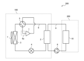
- FIG. 1 is a circuit diagram showing the configuration of a refrigeration cycle device 300 according to an embodiment.
- the refrigeration cycle device 300 includes a heat source device 100 and a utilization device 200.
- a vapor compression type refrigeration cycle operation using a refrigerant is performed in the heat source device 100.
- the utilization device 200 is, for example, a water heater, an air handling unit, an indoor unit of an air conditioner, or the like.
- a configuration in which refrigeration cycle device 300 is an indirect expansion type air conditioner will be described. More specifically, the refrigeration cycle device 300 will be described in a case where the heat source device 100 is an outdoor unit installed outdoors and the usage device 200 is an indoor unit of an air conditioner that uses a heat medium.
- the heat source device 100 includes a compressor 1, a heat source side heat exchanger 3, an air blower 7, an expansion valve 4, a load side heat exchanger 2, a four-way valve 5, and refrigerant piping. 6 is provided.
- the heat source device 100 connects a compressor 1, a four-way valve 5, a heat source side heat exchanger 3, an expansion valve 4, and a load side heat exchanger 2 in an annular manner via a refrigerant pipe 6, so that a refrigerant such as carbon dioxide Constitutes a circulating refrigerant circuit.
- the refrigerant piping 6 includes a first refrigerant piping section 6a through which a cold, low-pressure gas refrigerant sucked into the compressor 1 flows.
- the compressor 1 sucks and compresses a cold temperature and low pressure gas refrigerant flowing through the first refrigerant piping section 6a, and discharges the gas refrigerant in a high temperature and high pressure state.
- a four-way valve 5 is provided on the discharge side of the compressor 1.
- the four-way valve 5 can switch the direction in which the refrigerant flows. However, the four-way valve 5 may not be provided and the flow of the refrigerant may be constant.
- the four-way valve 5 can be switched to the flow path shown by the broken line in FIG. 1 during cooling operation and defrosting operation, and can be switched to the flow path shown by the solid line in FIG. 1 during heating operation.
- the load-side heat exchanger 2 exchanges heat between the refrigerant flowing through the refrigerant pipe 6 and the heat medium flowing through the usage-side pipe 9, which will be described later.
- the expansion valve 4 reduces the pressure of the high-pressure refrigerant and adjusts the pressure and flow rate of the refrigerant.
- the heat source side heat exchanger 3 exchanges heat between the refrigerant passing through the heat source side heat exchanger 3 and air.
- the blower 7 sends air to the heat source side heat exchanger 3. In the heat source side heat exchanger 3, the refrigerant exchanges heat with outdoor air sent by the blower 7, for example.
- the utilization device 200 has a utilization side heat exchanger 10.
- the utilization device 200 and the heat source device 100 are connected by a utilization side piping 9. More specifically, the load-side heat exchanger 2 and the usage-side heat exchanger 10 are connected by the usage-side piping 9.
- the utilization device 200 connects the load-side heat exchanger 2, the utilization-side heat exchanger 10, and the pump 8 in an annular manner via the utilization-side piping 9, and constitutes a heat medium circuit in which a heat medium such as water or brine circulates. do.
- the heat medium flowing through the user-side piping 9 exchanges heat with the refrigerant flowing through the refrigerant piping 6 in the load-side heat exchanger 2 .
- the pump 8 pressurizes the heat medium and circulates it within the heat medium circuit.
- the user-side heat exchanger 10 exchanges heat between the heat medium and the air in the air-conditioned space.
- the refrigeration cycle device 300 may be a direct expansion type air conditioner.
- the load-side heat exchanger 2 is not provided in the refrigeration cycle device 300, and the usage-side heat exchanger 10 functions as a load-side heat exchanger.
- the compressor 1, the heat source side heat exchanger 3, and the user side heat exchanger 10 functioning as a load side heat exchanger are connected in an annular manner by refrigerant piping. Therefore, a refrigerant circuit in which refrigerant circulates through the refrigerant pipes is formed, and the refrigeration cycle device 300, which is an air conditioner, performs vapor compression refrigeration cycle operation.
- the refrigeration cycle device 300 is not limited to an air conditioner.
- the refrigeration cycle device 300 may be another device such as a water heater, a chiller, or a heat storage device.
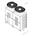
- FIG. 2 is an external perspective view of the heat source device 100 of the refrigeration cycle device 300 according to the embodiment.
- the refrigeration cycle device 300 is an indirect expansion type air conditioner
- the heat source device 100 is an outdoor unit of the air conditioner.
- the arrows shown in FIG. 2 indicate the front-rear direction of the heat source device 100, and the arrows indicate the direction from the back to the front.
- the heat source device 100 has a housing 100a. Inside the casing 100a, the compressor 1, the heat source side heat exchanger 3, the blower 7, the expansion valve 4, and the load side are included in the part surrounded by the broken line showing the heat source device 100 in FIG.
- a heat exchanger 2, a four-way valve 5, a refrigerant pipe 6, and a portion of a user-side pipe 9 are accommodated (not shown).
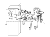
- FIG. 3 is a schematic diagram illustrating the configuration of the refrigerant pipe 6 covered with the soundproofing material 20 according to the embodiment.
- FIG. 3 shows the compressor 1 and the first refrigerant piping section 6a housed in the housing 100a of the heat source device 100.
- the first refrigerant piping section 6a which is a part of the refrigerant piping 6, is a portion surrounded by a broken line in FIG.
- FIG. 4 is a schematic cross-sectional view schematically showing the refrigerant pipe 6 covered with the soundproofing material 20 of FIG. 3.
- FIG. 4 shows a cross section of the first refrigerant pipe section 6a, which is a part of the refrigerant pipe 6 covered with the soundproofing material 20, perpendicular to the central axis.
- the soundproofing material 20 is provided so as to cover the entire outer peripheral surface of the refrigerant pipe 6 in the circumferential direction.
- the soundproof material 20 is formed from a damping material 21 and a sound absorbing material 22.
- the damping material 21 is provided on the outer peripheral surface of the refrigerant pipe 6 over the entire circumferential direction.
- the sound absorbing material 22 is provided on the outer peripheral surface of the vibration damping material 21 over the entire circumferential direction.
- the soundproofing material 20 can be provided at multiple locations on the refrigerant pipe 6. The portion of the refrigerant pipe 6 where the soundproofing material 20 is provided and the number of soundproofing materials 20 provided are not limited.
- soundproofing material 20 is provided in three parts of the first refrigerant piping section 6a. That is, the soundproofing material 20 includes a first soundproofing material 20a, a second soundproofing material 20b, and a third soundproofing material 20c.
- the soundproofing material 20 includes a first soundproofing material 20a, a second soundproofing material 20b, and a third soundproofing material 20c.
- soundproofing material 20 it shall include both the singular and plural.
- the range in which the plurality of soundproofing materials 20 cover the first refrigerant piping section 6a and the number of soundproofing materials 20 are not limited to the illustrated example.
- one soundproofing material 20 may cover from the outer peripheral surface of the refrigerant pipe 6 covered with the first soundproofing material 20a in FIG. 3 to the outer peripheral surface of the refrigerant piping 6 covered with the third soundproofing material 20c.
- the outer circumferential surface of the refrigerant pipe 6 between the first sound insulating material 20a and the second sound insulating material 20b and the outer circumferential surface of the refrigerant pipe 6 between the second sound insulating material 20b and the third sound insulating material 20c are respectively It may be covered with a No.
- the first soundproofing material 20a to the third soundproofing material 20c may have different sizes. That is, when a plurality of soundproofing materials 20 are provided, the sizes of each soundproofing material 20 do not need to be the same.
- the damping material 21 is a member that suppresses the vibration and sound pressure of the object by converting the vibration of the object into thermal energy and dissipating it into the air.
- the damping material 21 of this embodiment which is attached to the refrigerant pipe 6 which is tubular and has a bent portion, is made of an elastically deformable material such as rigid resin or rubber so that it can be easily attached to the refrigerant pipe 6. is desirable.
- the damping material 21 is made of a vibration damping material such as butyl rubber with a specific gravity of about 2.6 or rubber with a specific gravity of about 2.4, for example.
- the damping material 21 suppresses vibrations that occur when the refrigerant flows through the refrigerant pipe 6. Therefore, the sound radiated from the surface of the refrigerant pipe 6 due to vibration can be reduced.
- the damping material 21 is composed of a sheet-shaped member.
- a sheet-shaped damping material 21 is wound around the outer peripheral surface of the refrigerant pipe 6 in the circumferential direction CR.
- the damping material 21 has a first end surface 21 a and a second end surface 21 b that extend along the central axis of the refrigerant pipe 6 .
- the first end surface 21a and the second end surface 21b are end surfaces of the sheet-shaped damping material 21.
- the damping material 21 is provided on the outer peripheral surface of the refrigerant pipe 6 so that the first end surface 21a and the second end surface 21b are in surface contact with each other. That is, in the example shown in FIG.
- the damping material 21 is wound around the refrigerant pipe 6 such that the starting part and the ending part of the sheet-shaped damping material 21 do not overlap.
- the first end surface 21a and the second end surface 21b are in surface contact.
- the refrigerant pipe 6 is placed by overlapping the winding start part and the winding end part of the vibration damping material 21. It may be provided on the outer peripheral surface of the.
- the sound absorbing material 22 is a member that converts the energy of sound waves transmitted in the air into thermal energy and absorbs it.
- the sound absorbing material 22 is made of, for example, a porous material such as felt or glass wool. Since the sound radiated from the refrigerant pipe 6 is absorbed by the sound absorbing material 22, the sound generated in the refrigerant pipe 6 is less likely to be radiated to the outside of the sound absorbing material 22, and the noise is reduced.
- the sound absorbing material 22 is composed of a sheet-shaped member.
- a sheet-shaped sound absorbing material 22 is wound around the outer peripheral surface of the damping material 21 in the circumferential direction CR.
- the sound absorbing material 22 has a first end surface 22 a and a second end surface 22 b that extend along the central axis of the refrigerant pipe 6 .
- the first end surface 22a and the second end surface 22b are end surfaces of the sheet-shaped sound absorbing material 22.
- the sound absorbing material 22 is provided on the outer circumferential surface of the damping material 21 so that the first end surface 22a and the second end surface 22b are in surface contact with each other. That is, in the example of FIG.
- the sound absorbing material 22 is wound around the damping material 21 so that the winding start part and the winding end part of the sheet-shaped sound absorbing material 22 do not overlap, and The first end surface 22a and the second end surface 22b are in surface contact. Note that if it is difficult to provide the first end surface 22a and the second end surface 22b of the sound absorbing material 22 in contact with each other, the outer periphery of the damping material 21 may be formed by overlapping the winding start part and the winding end part of the sound absorbing material 22. It may be provided on the surface.
- a sound absorbing material 22 is attached to the outer circumferential surface of the vibration damping material 21, so that the outer circumferential surface of the sound insulating material 20 is formed by the sound absorbing material 22. By doing so, the function of the sound absorbing material 22 can be exerted without impairing its function.
- the materials of the damping material 21 and the sound absorbing material 22 that form the sound insulation material 20 may be changed depending on the part of the refrigerant pipe 6 where the sound insulation material 20 is provided.
- the temperature of the refrigerant pipe 6 on the discharge side of the compressor 1 becomes high.
- the refrigerant pipe 6 on the discharge side of the compressor 1 is provided with a damping material 21 made of a material that can withstand even when the outer peripheral surface of the refrigerant pipe 6 becomes high temperature, and a damping material 21 that is made of a material that can withstand even when the outer peripheral surface of the refrigerant pipe 6 becomes high temperature.
- a sound insulating material 20 having a sound absorbing material 22 made of a material that can withstand even the harshest conditions may be changed depending on the part of the refrigerant pipe 6 where the sound insulation material 20 is provided.
- the temperature of the refrigerant pipe 6 on the discharge side of the compressor 1 becomes high.
- the refrigerant pipe 6 on the discharge side of the compressor 1
- FIG. 4 in the circumferential direction CR of the refrigerant pipe 6, the position where the first end surface 21a and the second end surface 21b of the vibration damping material 21 are in contact, and the position where the first end surface 22a and the second end surface 22b of the sound absorbing material 22 are in contact with each other are shown.
- the contact position is misaligned.
- the outer peripheral surface of the refrigerant pipe 6 is covered with at least a damping material 21 or a sound absorbing material 22. Therefore, since the function of either the damping material 21 or the sound absorbing material 22 is maintained, it is possible to suppress a decrease in the noise reduction effect of the sound insulating material 20.
- the position where the first end face 21a and the second end face 21b of the vibration damping material 21 contact and the position where the first end face 22a and the second end face 22b of the sound absorbing material 22 contact are in the circumferential direction of the refrigerant pipe 6. It may be at the same position in CR.
- the soundproofing material 20 is fixed by a fixture 23.
- the fixture 23 is string-shaped and is provided so as to surround the outer peripheral surface of the sound absorbing material 22 in the circumferential direction CR so that the sound insulating material 20 is fixed to the refrigerant pipe 6.
- the fixture 23 may cause the soundproof material 20 to come off from the refrigerant pipe 6, create a gap between the refrigerant pipe 6 and the damping material 21, or create a gap between the vibration damper 21 and the sound absorbing material 22. This can be prevented. Since no gap is created between the refrigerant pipe 6 and the soundproof material 20, the noise reduction effect of the soundproof material 20 is improved.
- the shape of the fixture 23 is not limited to a string shape. Further, it is not necessary to surround and fix the soundproofing material 20 in the circumferential direction CR, and for example, a fixture 23 that fixes the winding start part and the winding end part of the sound absorbing material 22 outside the vibration damping material 21 may be used. It may be provided. Note that, in order to prevent the sound absorption performance of the sound absorbing material 22 from deteriorating, it is desirable that the fixture 23 has a small portion that presses down the sound absorbing material 22. Further, the number of fixtures 23 and the positions at which they are fixed may be selected depending on the size of the soundproofing material 20. In other words, the number of fixtures 23 used to secure one soundproofing material 20 is not limited. Further, the position where the soundproofing material 20 is fixed with the fixture 23 is not limited either.
- FIG. 5 is a graph showing a noise level ratio comparing the noise levels before and after providing the soundproofing material 20 of FIG. 3.
- the noise level was acquired by a microphone for noise measurement installed at a predetermined distance from the back of the casing 100a of the heat source device 100 shown in FIG.
- the noise level ratio is a value derived from the noise levels measured before and after installing the soundproofing material 20 in FIG. is the proportion of the noise level. More specifically, the noise level ratio is a value obtained by dividing the noise level before providing the soundproofing material 20 by the noise level after providing the soundproofing material 20. Therefore, when the noise level ratio exceeds 100.0%, it can be determined that the soundproofing material 20 has a noise reduction effect.
- the vertical axis shows the noise level ratio (%)
- the horizontal axis shows the frequency (Hz) after 1/3 octave analysis on a logarithmic scale.
- the noise level ratio shows a value close to 110.0% in the range from 3000 Hz to 10000 Hz. Therefore, it can be determined that the effect of noise reduction by the soundproof material 20 is large in the frequency range from 3000 Hz to 10000 Hz.
- the total noise level before installing the soundproofing material 20 which was obtained by a microphone for noise measurement installed at a predetermined distance on the back of the housing 100a, was 66.2 dB (A), and when the soundproofing material 20 was installed The total noise level after the test was 65.1 dB(A). Since the total noise level after providing the soundproofing material 20 is reduced by 1.1 dB (A), it can be said that the noise generated in the refrigerant pipe 6 is reduced by the soundproofing material 20. Note that the total noise level is a value derived based on the noise level at each frequency from 80 Hz to 10,000 Hz.
- the refrigeration cycle device 300 includes the compressor 1, the heat source side heat exchanger 3, the load side heat exchanger 2, the compressor 1 and the heat source side heat exchanger 3.
- a refrigerant pipe 6 is provided between the load-side heat exchanger and forms a refrigerant circuit in which refrigerant circulates, and the outer peripheral surface of at least a portion of the refrigerant pipe 6 is covered with a soundproofing material 20 over the entire circumferential direction.
- the soundproofing material 20 includes a damping material 21 provided so as to cover the entire circumferential surface of at least a portion of the refrigerant pipe 6, and a damping material 21 provided so as to cover the entire circumferential surface of the vibration damping material 21. It has a sound absorbing material 22.
- the load-side heat exchanger 2 is an example of a load-side heat exchanger
- the usage-side heat exchanger 10 may be provided as a load-side heat exchanger.
- the outer circumferential surface of at least a portion of the refrigerant pipe 6 is covered in the entire circumferential direction with the sound insulating material 20 having the damping material 21 and the sound absorbing material 22. Since vibration of the refrigerant pipe 6 is suppressed by the damping material 21, it is possible to reduce sound radiated from the surface of the refrigerant pipe 6 due to the vibration. Further, since the sound emitted from the refrigerant pipe 6 is absorbed by the sound absorbing material 22, the sound generated in the refrigerant pipe 6 is less likely to be radiated to the outside of the sound absorbing material 22, and noise is reduced. Therefore, the noise generated in the refrigerant pipe 6 can be reduced by the soundproofing material 20.
- the outer peripheral surface of at least a portion of the refrigerant pipe 6 is in contact with the damping material 21 over the entire circumferential direction, and the outer peripheral surface of the vibration damping material 21 is made of sound absorbing material over the entire circumferential direction. I am in contact with 22.
- the sound insulating material 20 including the damping material 21 and the sound absorbing material 22 is stacked on the outer circumferential surface of the refrigerant pipe 6 without any gaps. Therefore, the noise reduction effect of the soundproofing material 20 is improved.
- the refrigeration cycle device 300 further includes a housing 100a that houses the compressor 1 and the heat source side heat exchanger 3, and the refrigerant pipe 6 is connected to the casing 100a through which the refrigerant flowing into the compressor 1 flows.
- a housing 100a that houses the compressor 1 and the heat source side heat exchanger 3, and the refrigerant pipe 6 is connected to the casing 100a through which the refrigerant flowing into the compressor 1 flows.
- 1 refrigerant piping section 6a, the first refrigerant piping section 6a is provided inside the housing 100a, and at least a part of the refrigerant piping 6 covered with the soundproofing material 20 is connected to the first refrigerant piping section 6a. It is.
- the noise generated in the first refrigerant piping section 6a located inside the housing 100a can be reduced. Therefore, the noise generated from the housing 100a can be reduced, and the influence of the noise generated from the housing 100a on the surroundings can be reduced.
- the damping material 21 has a sheet shape having a first end surface 21a and a second end surface 21b extending along the central axis of the refrigerant pipe 6, and the damping material The first end surface 21a of the damping material 21 and the second end surface 21b of the damping material 21 are in surface contact with each other.
- the first end surface 21a and the second end surface 21b of the vibration damping material 21 are provided on the outer circumferential surface of the refrigerant pipe 6 without overlapping, with the first end surface 21a and the second end surface 21b in surface contact. Therefore, the damping material 21 can cover the entire outer peripheral surface of the refrigerant pipe 6 in the circumferential direction without any gaps. Further, since the outer circumferential surface of the damping material 21 is in a flat state, it becomes possible to cover the outer circumferential surface of the damping material 21 with the sound absorbing material 22 without any gaps in the entire circumferential direction. As a result, there is no gap between the refrigerant pipe 6, the damping material 21, and the sound absorbing material 22, and the noise reduction effect of the sound insulating material 20 is improved.
- the sound absorbing material 22 has a sheet shape having a first end surface 22a and a second end surface 22b extending along the central axis of the refrigerant pipe 6.
- the first end surface 22a and the second end surface 22b of the sound absorbing material 22 are in surface contact.
- the first end surface 22a and the second end surface 22b of the sound absorbing material 22 are provided on the outer circumferential surface of the vibration damping material 21 without overlapping, with the first end surface 22a and the second end surface 22b in surface contact. Since the sound absorbing material 22 can cover the entire outer peripheral surface of the damping material 21 in the circumferential direction without any gaps, the noise reduction effect of the sound insulating material 20 is improved.
- the position where the first end surface 21a and the second end surface 21b of the damping material 21 are in contact with each other in the circumferential direction CR of the refrigerant pipe 6 is the position of the sound absorbing material 22. This is different from the position where the first end surface 22a and the second end surface 22b are in contact. For this reason, if a gap occurs at the same time in the surface where the first end surface 21a and the second end surface 21b of the damping material 21 contact and the surface where the first end surface 22a and the second end surface 22b of the sound absorbing material 22 contact. However, since the function of either the vibration damping material 21 or the sound absorbing material 22 is maintained, a decrease in the noise reduction effect of the sound insulating material 20 can be suppressed.
- the sheet-shaped damping material 21 may have a tube shape instead of a sheet shape.
- the damping material 21 may have a seamless cylindrical shape that extends along the central axis of the refrigerant pipe 6. According to this configuration, the damping material 21 does not separate from the refrigerant pipe 6. Therefore, the effect of suppressing vibration of the refrigerant pipe 6 by the damping material 21 is stably maintained. Further, since the damping material 21 has no seams, the outer circumferential surface of the refrigerant pipe 6 can be reliably covered in the entire circumferential direction without any gaps. Therefore, the vibration suppressing effect of the damping material 21 is improved.
- the sheet-shaped sound absorbing material 22 has been described above.
- the sound absorbing material 22 may have a tube shape instead of a sheet shape.
- the sound absorbing material 22 may have a seamless cylindrical shape extending along the central axis of the refrigerant pipe 6. According to this configuration, the sound absorbing material 22 does not separate from the refrigerant pipe 6. Therefore, the effect of the sound absorbing material 22 absorbing the sound radiated from the refrigerant pipe 6 is stably maintained.
- the sound absorbing material 22 has no seams, the outer circumferential surface of the vibration damping material 21 can be reliably covered over the entire circumferential direction without any gaps. Therefore, the sound absorbing effect of the sound absorbing material 22 is improved.
Landscapes
- Engineering & Computer Science (AREA)
- General Engineering & Computer Science (AREA)
- Mechanical Engineering (AREA)
- Physics & Mathematics (AREA)
- Thermal Sciences (AREA)
- Compressor (AREA)
Priority Applications (2)
| Application Number | Priority Date | Filing Date | Title |
|---|---|---|---|
| JP2024516024A JPWO2023203742A1 (https=) | 2022-04-22 | 2022-04-22 | |
| PCT/JP2022/018505 WO2023203742A1 (ja) | 2022-04-22 | 2022-04-22 | 冷凍サイクル装置 |
Applications Claiming Priority (1)
| Application Number | Priority Date | Filing Date | Title |
|---|---|---|---|
| PCT/JP2022/018505 WO2023203742A1 (ja) | 2022-04-22 | 2022-04-22 | 冷凍サイクル装置 |
Publications (1)
| Publication Number | Publication Date |
|---|---|
| WO2023203742A1 true WO2023203742A1 (ja) | 2023-10-26 |
Family
ID=88419641
Family Applications (1)
| Application Number | Title | Priority Date | Filing Date |
|---|---|---|---|
| PCT/JP2022/018505 Ceased WO2023203742A1 (ja) | 2022-04-22 | 2022-04-22 | 冷凍サイクル装置 |
Country Status (2)
| Country | Link |
|---|---|
| JP (1) | JPWO2023203742A1 (https=) |
| WO (1) | WO2023203742A1 (https=) |
Citations (4)
| Publication number | Priority date | Publication date | Assignee | Title |
|---|---|---|---|---|
| JP2005207550A (ja) * | 2004-01-26 | 2005-08-04 | Inaba Denki Sangyo Co Ltd | 管継手 |
| JP2007187324A (ja) * | 2004-01-28 | 2007-07-26 | Takayasu Co Ltd | 送風ダクトの騒音低減方法 |
| JP2014126122A (ja) * | 2012-12-26 | 2014-07-07 | Mitsubishi Heavy Ind Ltd | 配管振動の抑制装置 |
| WO2018198322A1 (ja) * | 2017-04-28 | 2018-11-01 | 三菱電機株式会社 | 冷凍サイクル装置及びこの冷凍サイクル装置を備えた電気機器 |
Family Cites Families (4)
| Publication number | Priority date | Publication date | Assignee | Title |
|---|---|---|---|---|
| JPS61180411A (ja) * | 1985-02-05 | 1986-08-13 | Toshiba Corp | 巻鉄心構成体の製造方法 |
| JPH04133404U (ja) * | 1991-06-03 | 1992-12-11 | 鐘淵化学工業株式会社 | 磁性ゴムロール |
| WO1999017047A1 (en) * | 1997-09-29 | 1999-04-08 | Shishiai-Kabushikigaisha | Sound-proof pipe member |
| WO1999017048A1 (en) * | 1997-10-01 | 1999-04-08 | Shishiai-Kabushikigaisha | Fire-resistant sound-proof pipe |
-
2022
- 2022-04-22 JP JP2024516024A patent/JPWO2023203742A1/ja active Pending
- 2022-04-22 WO PCT/JP2022/018505 patent/WO2023203742A1/ja not_active Ceased
Patent Citations (4)
| Publication number | Priority date | Publication date | Assignee | Title |
|---|---|---|---|---|
| JP2005207550A (ja) * | 2004-01-26 | 2005-08-04 | Inaba Denki Sangyo Co Ltd | 管継手 |
| JP2007187324A (ja) * | 2004-01-28 | 2007-07-26 | Takayasu Co Ltd | 送風ダクトの騒音低減方法 |
| JP2014126122A (ja) * | 2012-12-26 | 2014-07-07 | Mitsubishi Heavy Ind Ltd | 配管振動の抑制装置 |
| WO2018198322A1 (ja) * | 2017-04-28 | 2018-11-01 | 三菱電機株式会社 | 冷凍サイクル装置及びこの冷凍サイクル装置を備えた電気機器 |
Also Published As
| Publication number | Publication date |
|---|---|
| JPWO2023203742A1 (https=) | 2023-10-26 |
Similar Documents
| Publication | Publication Date | Title |
|---|---|---|
| JP2009014228A (ja) | 冷凍装置 | |
| JP5287614B2 (ja) | ヒートポンプ室外機 | |
| US20120167608A1 (en) | Outdoor unit for air conditioner | |
| JPWO2019211894A1 (ja) | 地熱ヒートポンプシステム | |
| EP3745033B1 (en) | Heat pump hot water supply outdoor unit | |
| JP5277735B2 (ja) | 冷凍装置 | |
| JP2005241236A (ja) | 空調機の室外機の配管構造 | |
| US20130160479A1 (en) | Sound-attenuating housing | |
| AU752348B2 (en) | Structure and method for attenuating noise from outdoor unit of air conditioner | |
| JP2013088003A (ja) | 室外機 | |
| WO2023203742A1 (ja) | 冷凍サイクル装置 | |
| US20100247339A1 (en) | Noise-attenuating device for hvac and refrigeration systems | |
| WO2018109846A1 (ja) | ヒートポンプ給湯室外機 | |
| JP6631706B2 (ja) | ヒートポンプ給湯室外機 | |
| JPWO2019082300A1 (ja) | 冷凍サイクル装置用ユニット、冷凍サイクル装置及び電気機器 | |
| CN112166250B (zh) | 压缩机单元、空调装置的室外机以及空调装置 | |
| WO2018198322A1 (ja) | 冷凍サイクル装置及びこの冷凍サイクル装置を備えた電気機器 | |
| JP2010038460A (ja) | 空気調和装置の室外ユニット | |
| KR200154185Y1 (ko) | 공기조화기의 소음방지장치 | |
| JP5245550B2 (ja) | 冷凍装置 | |
| JP7695580B2 (ja) | 熱源ユニットおよび冷凍サイクル装置 | |
| WO2021064984A1 (ja) | 冷凍サイクル装置 | |
| US20250383100A1 (en) | Sound and vibration damping enclosures for refrigerant compressors of climate control systems | |
| JP2015075252A (ja) | 冷凍サイクル装置 | |
| KR100432694B1 (ko) | 에어컨 실외기의 소음 저감 구조 |
Legal Events
| Date | Code | Title | Description |
|---|---|---|---|
| 121 | Ep: the epo has been informed by wipo that ep was designated in this application |
Ref document number: 22938542 Country of ref document: EP Kind code of ref document: A1 |
|
| ENP | Entry into the national phase |
Ref document number: 2024516024 Country of ref document: JP Kind code of ref document: A |
|
| NENP | Non-entry into the national phase |
Ref country code: DE |
|
| 122 | Ep: pct application non-entry in european phase |
Ref document number: 22938542 Country of ref document: EP Kind code of ref document: A1 |