WO2023195321A1 - 正極材料およびそれを用いた電池 - Google Patents
正極材料およびそれを用いた電池 Download PDFInfo
- Publication number
- WO2023195321A1 WO2023195321A1 PCT/JP2023/010402 JP2023010402W WO2023195321A1 WO 2023195321 A1 WO2023195321 A1 WO 2023195321A1 JP 2023010402 W JP2023010402 W JP 2023010402W WO 2023195321 A1 WO2023195321 A1 WO 2023195321A1
- Authority
- WO
- WIPO (PCT)
- Prior art keywords
- solid electrolyte
- positive electrode
- battery
- molar ratio
- active material
- Prior art date
- Legal status (The legal status is an assumption and is not a legal conclusion. Google has not performed a legal analysis and makes no representation as to the accuracy of the status listed.)
- Ceased
Links
Images


Classifications
-
- H—ELECTRICITY
- H01—ELECTRIC ELEMENTS
- H01M—PROCESSES OR MEANS, e.g. BATTERIES, FOR THE DIRECT CONVERSION OF CHEMICAL ENERGY INTO ELECTRICAL ENERGY
- H01M4/00—Electrodes
- H01M4/02—Electrodes composed of, or comprising, active material
- H01M4/62—Selection of inactive substances as ingredients for active masses, e.g. binders, fillers
-
- H—ELECTRICITY
- H01—ELECTRIC ELEMENTS
- H01M—PROCESSES OR MEANS, e.g. BATTERIES, FOR THE DIRECT CONVERSION OF CHEMICAL ENERGY INTO ELECTRICAL ENERGY
- H01M10/00—Secondary cells; Manufacture thereof
- H01M10/05—Accumulators with non-aqueous electrolyte
- H01M10/052—Li-accumulators
-
- H—ELECTRICITY
- H01—ELECTRIC ELEMENTS
- H01M—PROCESSES OR MEANS, e.g. BATTERIES, FOR THE DIRECT CONVERSION OF CHEMICAL ENERGY INTO ELECTRICAL ENERGY
- H01M10/00—Secondary cells; Manufacture thereof
- H01M10/05—Accumulators with non-aqueous electrolyte
- H01M10/052—Li-accumulators
- H01M10/0525—Rocking-chair batteries, i.e. batteries with lithium insertion or intercalation in both electrodes; Lithium-ion batteries
-
- H—ELECTRICITY
- H01—ELECTRIC ELEMENTS
- H01M—PROCESSES OR MEANS, e.g. BATTERIES, FOR THE DIRECT CONVERSION OF CHEMICAL ENERGY INTO ELECTRICAL ENERGY
- H01M10/00—Secondary cells; Manufacture thereof
- H01M10/05—Accumulators with non-aqueous electrolyte
- H01M10/056—Accumulators with non-aqueous electrolyte characterised by the materials used as electrolytes, e.g. mixed inorganic/organic electrolytes
- H01M10/0561—Accumulators with non-aqueous electrolyte characterised by the materials used as electrolytes, e.g. mixed inorganic/organic electrolytes the electrolyte being constituted of inorganic materials only
- H01M10/0562—Solid materials
-
- H—ELECTRICITY
- H01—ELECTRIC ELEMENTS
- H01M—PROCESSES OR MEANS, e.g. BATTERIES, FOR THE DIRECT CONVERSION OF CHEMICAL ENERGY INTO ELECTRICAL ENERGY
- H01M4/00—Electrodes
- H01M4/02—Electrodes composed of, or comprising, active material
- H01M4/13—Electrodes for accumulators with non-aqueous electrolyte, e.g. for lithium-accumulators; Processes of manufacture thereof
-
- H—ELECTRICITY
- H01—ELECTRIC ELEMENTS
- H01M—PROCESSES OR MEANS, e.g. BATTERIES, FOR THE DIRECT CONVERSION OF CHEMICAL ENERGY INTO ELECTRICAL ENERGY
- H01M4/00—Electrodes
- H01M4/02—Electrodes composed of, or comprising, active material
- H01M4/13—Electrodes for accumulators with non-aqueous electrolyte, e.g. for lithium-accumulators; Processes of manufacture thereof
- H01M4/131—Electrodes based on mixed oxides or hydroxides, or on mixtures of oxides or hydroxides, e.g. LiCoOx
-
- H—ELECTRICITY
- H01—ELECTRIC ELEMENTS
- H01M—PROCESSES OR MEANS, e.g. BATTERIES, FOR THE DIRECT CONVERSION OF CHEMICAL ENERGY INTO ELECTRICAL ENERGY
- H01M4/00—Electrodes
- H01M4/02—Electrodes composed of, or comprising, active material
- H01M4/36—Selection of substances as active materials, active masses, active liquids
-
- H—ELECTRICITY
- H01—ELECTRIC ELEMENTS
- H01M—PROCESSES OR MEANS, e.g. BATTERIES, FOR THE DIRECT CONVERSION OF CHEMICAL ENERGY INTO ELECTRICAL ENERGY
- H01M4/00—Electrodes
- H01M4/02—Electrodes composed of, or comprising, active material
- H01M4/36—Selection of substances as active materials, active masses, active liquids
- H01M4/362—Composites
- H01M4/366—Composites as layered products
-
- H—ELECTRICITY
- H01—ELECTRIC ELEMENTS
- H01M—PROCESSES OR MEANS, e.g. BATTERIES, FOR THE DIRECT CONVERSION OF CHEMICAL ENERGY INTO ELECTRICAL ENERGY
- H01M4/00—Electrodes
- H01M4/02—Electrodes composed of, or comprising, active material
- H01M4/36—Selection of substances as active materials, active masses, active liquids
- H01M4/48—Selection of substances as active materials, active masses, active liquids of inorganic oxides or hydroxides
- H01M4/52—Selection of substances as active materials, active masses, active liquids of inorganic oxides or hydroxides of nickel, cobalt or iron
- H01M4/525—Selection of substances as active materials, active masses, active liquids of inorganic oxides or hydroxides of nickel, cobalt or iron of mixed oxides or hydroxides containing iron, cobalt or nickel for inserting or intercalating light metals, e.g. LiNiO2, LiCoO2 or LiCoOxFy
-
- H—ELECTRICITY
- H01—ELECTRIC ELEMENTS
- H01M—PROCESSES OR MEANS, e.g. BATTERIES, FOR THE DIRECT CONVERSION OF CHEMICAL ENERGY INTO ELECTRICAL ENERGY
- H01M2300/00—Electrolytes
- H01M2300/0017—Non-aqueous electrolytes
- H01M2300/0065—Solid electrolytes
- H01M2300/0068—Solid electrolytes inorganic
-
- H—ELECTRICITY
- H01—ELECTRIC ELEMENTS
- H01M—PROCESSES OR MEANS, e.g. BATTERIES, FOR THE DIRECT CONVERSION OF CHEMICAL ENERGY INTO ELECTRICAL ENERGY
- H01M2300/00—Electrolytes
- H01M2300/0017—Non-aqueous electrolytes
- H01M2300/0065—Solid electrolytes
- H01M2300/0068—Solid electrolytes inorganic
- H01M2300/008—Halides
-
- Y—GENERAL TAGGING OF NEW TECHNOLOGICAL DEVELOPMENTS; GENERAL TAGGING OF CROSS-SECTIONAL TECHNOLOGIES SPANNING OVER SEVERAL SECTIONS OF THE IPC; TECHNICAL SUBJECTS COVERED BY FORMER USPC CROSS-REFERENCE ART COLLECTIONS [XRACs] AND DIGESTS
- Y02—TECHNOLOGIES OR APPLICATIONS FOR MITIGATION OR ADAPTATION AGAINST CLIMATE CHANGE
- Y02E—REDUCTION OF GREENHOUSE GAS [GHG] EMISSIONS, RELATED TO ENERGY GENERATION, TRANSMISSION OR DISTRIBUTION
- Y02E60/00—Enabling technologies; Technologies with a potential or indirect contribution to GHG emissions mitigation
- Y02E60/10—Energy storage using batteries
Definitions
- the present disclosure relates to a positive electrode material and a battery using the same.
- Patent Document 1 discloses a solid electrolyte material containing Li, M, O, and X, and a battery using the same.
- M is at least one element selected from the group consisting of Nb and Ta
- X is at least one element selected from the group consisting of Cl, Br, and I.
- Patent Document 2 discloses a solid electrolyte material containing Li, M, O, X, and F, and a battery using the same.
- M is at least one element selected from the group consisting of Ta and Nb
- X is at least one element selected from the group consisting of Cl, Br, and I.
- Patent Document 3 discloses a positive electrode including a first solid electrolyte containing Li, M1, and F and covering at least a portion of the surface of a positive electrode active material, and a second solid electrolyte containing Li, M2, O, and X. Materials are disclosed.
- M1 is at least one selected from the group consisting of Ti, Al, and Zr
- M2 is at least one selected from the group consisting of Ta and Nb
- X is F, Cl , Br and I.
- An object of the present disclosure is to provide a positive electrode material suitable for improving the charging and discharging characteristics of a battery.
- the positive electrode material of the present disclosure includes: comprising a positive electrode active material, a first solid electrolyte, and a second solid electrolyte,
- the first solid electrolyte consists of Li, M1, and X1
- the second solid electrolyte consists of Li, M2, O, and X2
- M1 is at least one selected from the group consisting of Al, Ti, and Zr
- M2 is at least one selected from Group 5 elements
- X1 and X2 are each independently at least one selected from the group consisting of F, Cl, Br, and I, and contain F.
- the present disclosure provides a positive electrode material suitable for improving the charging and discharging characteristics of a battery.
- FIG. 1 is a cross-sectional view showing a schematic configuration of a positive electrode material according to a first embodiment.
- FIG. 2 is a cross-sectional view showing a schematic configuration of a positive electrode material according to a modified example.
- FIG. 3 is a sectional view showing a schematic configuration of a battery according to the second embodiment.
- FIG. 4 is a schematic diagram of a pressure molding die 300 used to evaluate the ionic conductivity of a solid electrolyte.
- FIG. 5 is a graph showing a Cole-Cole plot obtained by measuring the electrochemical impedance of the second solid electrolyte of Example 1.
- FIG. 6 is a graph showing Cole-Cole plots obtained by electrochemical impedance measurements of the mixed powder of Example 1 at 25° C. before and after storage for 48 hours.
- FIG. 7 is a graph showing a Cole-Cole plot obtained by measuring the electrochemical impedance of the battery of Example 1.
- Patent Document 1 discloses Li, M, O, and X (M is at least one element selected from the group consisting of Nb and Ta, and X is selected from the group consisting of Cl, Br, and I). discloses a solid electrolyte material containing at least one element).
- Patent Document 2 discloses that Li, M, O, X, and F (M is at least one element selected from the group consisting of Ta and Nb, and X is selected from the group consisting of Cl, Br, and I).
- Patent Documents 1 and 2 the above-mentioned solid electrolyte material is used in the positive electrode to improve the charging and discharging characteristics of the battery.
- Patent Document 3 discloses a positive electrode material that includes a positive electrode active material, a fluorine-containing solid electrolyte that covers the positive electrode active material, and an oxyhalide solid electrolyte. Patent Document 3 describes that since the solid electrolyte containing fluorine has high oxidation resistance, the reaction between the positive electrode active material and another solid electrolyte at high potential can be suppressed (that is, an oxidative decomposition layer is less likely to be formed). has been done.
- the present inventors have conducted extensive studies in order to realize a battery with improved charge and discharge characteristics. As a result, we came up with the positive electrode material of the present disclosure.
- the positive electrode material according to the first aspect of the present disclosure is comprising a positive electrode active material, a first solid electrolyte, and a second solid electrolyte
- the first solid electrolyte consists of Li, M1, and X1
- the second solid electrolyte consists of Li, M2, O, and X2
- M1 is at least one selected from the group consisting of Al, Ti, and Zr
- M2 is at least one selected from Group 5 elements
- X1 and X2 are each independently at least one selected from the group consisting of F, Cl, Br, and I, and contain F.
- the positive electrode material of the present disclosure is suitable for improving the charging and discharging characteristics of batteries. Furthermore, by setting M1 to at least one selected from the group consisting of Al, Ti, and Zr, the lithium ion conductivity of the first solid electrolyte is improved.
- M2 may include Nb. According to the above configuration, the lithium ion conductivity of the second solid electrolyte is improved.
- M2 may contain Nb and Ta. According to the above configuration, the lithium ion conductivity of the second solid electrolyte is improved.
- X2 may contain Cl. According to the above configuration, the lithium ion conductivity of the second solid electrolyte is improved.
- the second solid electrolyte is made of Li, Ta, Nb, O, Cl, and F. Good too. According to the above configuration, the lithium ion conductivity of the second solid electrolyte is improved.
- the molar ratio of Nb to M2 may be 0.50 or more. According to the above configuration, the thermodynamic contact stability between the second solid electrolyte and the first solid electrolyte is improved.
- the molar ratio of Nb to M2 may be 0.50 or more and 0.80 or less. According to the above configuration, the lithium ion conductivity of the second solid electrolyte is improved.
- the molar ratio of Nb to M2 may be 0.50 or more and 0.60 or less. According to the above configuration, the lithium ion conductivity of the second solid electrolyte is further improved.
- the molar ratio of F to X2 may be 0.02 or more and 0.40 or less. According to the above configuration, the lithium ion conductivity of the second solid electrolyte is improved.
- the molar ratio of F to X2 may be 0.02 or more and 0.08 or less. According to the above configuration, the lithium ion conductivity of the second solid electrolyte is further improved.
- the first solid electrolyte may be represented by the following compositional formula (1).
- M3 is at least one selected from the group consisting of Ti and Zr, and 0 ⁇ a ⁇ 1 is satisfied. According to the above configuration, the lithium ion conductivity of the first solid electrolyte is further improved.
- the first solid electrolyte may be represented by the following compositional formula (2).
- M4 is at least one selected from the group consisting of Zr, Ni, Fe, and Cr
- m is the valence of M4, and 0.1 ⁇ x ⁇ 0.9, 0 ⁇ y ⁇ 0.1, 0 ⁇ z ⁇ 0.1, and 0.8 ⁇ b ⁇ 1.2 are satisfied.
- the lithium ion conductivity of the first solid electrolyte is further improved.
- the first solid electrolyte may cover at least a part of the surface of the positive electrode active material. good. According to the above configuration, an increase in internal resistance at the positive electrode can be suppressed.
- the battery according to the fourteenth aspect of the present disclosure includes: A positive electrode containing the positive electrode material according to any one of the first to thirteenth aspects, a negative electrode; an electrolyte layer provided between the positive electrode and the negative electrode; Equipped with
- the battery of the present disclosure has excellent charge and discharge characteristics.
- the positive electrode material according to the first embodiment includes a first solid electrolyte and a second solid electrolyte.
- the first solid electrolyte consists of Li, M1, and X1.
- the second solid electrolyte consists of Li, M2, O, and X2.
- M1 is at least one selected from the group consisting of Al, Ti, and Zr.
- M2 is at least one selected from Group 5 elements.
- X1 and X2 are each independently at least one selected from the group consisting of F, Cl, Br, and I, and contain F.
- the first solid electrolyte is composed of Li, M1, and X1
- the first solid electrolyte may consist only of Li, M1, and X1.
- the second solid electrolyte consists of Li, M2, O, and X2".
- the positive electrode material according to the first embodiment contains an oxyhalide electrolyte as the second solid electrolyte, it exhibits high lithium ion conductivity and good initial charge/discharge characteristics. Furthermore, since the first solid electrolyte contains a fluoride solid electrolyte, it has excellent oxidation resistance. Furthermore, since the thermodynamic contact stability between the first solid electrolyte and the second solid electrolyte is high, formation of a high resistance phase due to side reactions of the solid electrolyte is suppressed. As a result, a battery including the positive electrode material according to the first embodiment exhibits high cycle characteristics. In this way, the positive electrode material according to the first embodiment can improve the charging and discharging characteristics of the battery.
- FIG. 1 is a cross-sectional view showing a schematic configuration of a positive electrode material 100 according to the first embodiment.
- the positive electrode material 100 includes a positive electrode active material 101, a first solid electrolyte 102, and a second solid electrolyte 103.
- the shape of the positive electrode active material 101 is, for example, particulate.
- the first solid electrolyte 102 is interposed between the positive electrode active material 101 and the second solid electrolyte 103.
- the shape of the first solid electrolyte 102 is, for example, particulate.
- the shape of the second solid electrolyte 103 is, for example, particulate. According to the second solid electrolyte 103, the positive electrode material 100 can ensure sufficient lithium ion conductivity.
- the positive electrode active material 101 does not need to be in direct contact with the second solid electrolyte 103. This is because the first solid electrolyte 102 interposed between the positive electrode active material 101 and the second solid electrolyte 103 has lithium ion conductivity.
- the positive electrode active material 101 the positive electrode active material 101, the first solid electrolyte 102, and the second solid electrolyte 103 will be explained in more detail.
- Examples of the positive electrode active material 101 include a lithium-containing transition metal oxide, a transition metal fluoride, a polyanionic material, a fluorinated polyanionic material, a transition metal sulfide, a transition metal oxyfluoride, a transition metal oxysulfide, or a transition metal oxynitride. It is.
- Examples of lithium-containing transition metal oxides are Li(Ni,Co,Al) O2 or LiCoO2 .
- the notation "(A, B, C)" in the chemical formula means "at least one selected from the group consisting of A, B, and C.”
- “(Ni, Co, Al)” is synonymous with “at least one selected from the group consisting of Ni, Co, and Al.”
- the particles of the positive electrode active material 101 may have a median diameter of 0.1 ⁇ m or more and 100 ⁇ m or less.
- the median diameter means the particle diameter when the cumulative volume in the volume-based particle size distribution is equal to 50%.
- the volume-based particle size distribution is measured, for example, by a laser diffraction measurement device or an image analysis device.
- the particles of the positive electrode active material 101 have a median diameter of 0.1 ⁇ m or more, the positive electrode active material 101, the first solid electrolyte 102, and the second solid electrolyte 103 can be well dispersed in the positive electrode material 100. This improves the charging and discharging characteristics of the battery.
- the particles of the positive electrode active material 101 have a median diameter of 100 ⁇ m or less, the lithium diffusion rate within the particles of the positive electrode active material 101 is improved. This allows the battery to operate at high output.
- the particles of the positive electrode active material 101 may have a larger median diameter than the particles of the first solid electrolyte 102 and the second solid electrolyte 103. Thereby, in the positive electrode material 100, the particles of the positive electrode active material 101, the first solid electrolyte 102, and the second solid electrolyte 103 can be well dispersed.
- the first solid electrolyte 102 consists of Li, M1, and X1.
- M1 is at least one selected from the group consisting of Al, Ti, and Zr. By setting M1 to at least one selected from the group consisting of Al, Ti, and Zr, the lithium ion conductivity of the first solid electrolyte is improved.
- X1 is at least one selected from the group consisting of F, Cl, Br, and I, and contains F.
- the positive electrode material 100 since the first solid electrolyte 102 has high oxidation resistance, the positive electrode material 100 has excellent oxidation resistance. Therefore, an increase in the internal resistance of the positive electrode material 100 at high potential is suppressed, and the charge/discharge characteristics of the battery can be improved.
- the first solid electrolyte 102 has high lithium ion conductivity.
- the high lithium ion conductivity is, for example, 1.0 ⁇ 10 ⁇ 7 S/cm or more. That is, the first solid electrolyte 102 may have a lithium ion conductivity of, for example, 1.0 ⁇ 10 ⁇ 7 S/cm or more.
- M1 is at least one selected from metal elements, the first solid electrolyte 102 can form a cation skeleton structure suitable for lithium ion conduction within the crystal lattice. Therefore, the first solid electrolyte exhibits high lithium ion conductivity. Therefore, the internal resistance of the positive electrode can be reduced.
- the first solid electrolyte 102 may contain elements that are inevitably mixed. Examples of such elements are hydrogen, oxygen or nitrogen. Such an element may be present in the raw material powder of the first solid electrolyte 102 or in the atmosphere for manufacturing or storing the first solid electrolyte 102.
- the first solid electrolyte 102 may be a material represented by the following compositional formula (1).
- M3 is at least one selected from the group consisting of Ti and Zr, and 0 ⁇ a ⁇ 1 is satisfied.
- the first solid electrolyte 102 may be a material represented by the following compositional formula (2).
- M4 is at least one selected from the group consisting of Zr, Ni, Fe, and Cr
- m is the valence of M4
- 0.1 ⁇ x ⁇ 0.9, 0 ⁇ y ⁇ 0.1, 0 ⁇ z ⁇ 0.1, and 0.8 ⁇ b ⁇ 1.2 are satisfied.
- compositional formula (2) when M4 includes multiple types of elements, m is the total value of the product of the composition ratio of each element and the valence of the element. For example, when M4 includes the element Me1 and the element Me2, the composition ratio of the element Me1 is a1 and the valence is m1, the composition ratio of the element Me2 is a2, and the valence of the element Me2 is m2, then m is It is expressed as m1a1+m2a2.
- the first solid electrolyte 102 may be crystalline or amorphous.
- the shape of the first solid electrolyte 102 is not limited. Examples of such shapes are needle-like, spherical, or ellipsoidal.
- the first solid electrolyte 102 may be particles.
- the solid electrolyte may have a median diameter of 0.1 ⁇ m or more and 100 ⁇ m or less. When the median diameter is within this range, the positive electrode active material 101, the first solid electrolyte 102, and the second solid electrolyte 103 can be well dispersed in the positive electrode material 100.
- the median diameter of the first solid electrolyte 102 may be 10 ⁇ m or less.
- the positive electrode active material 101, the first solid electrolyte 102, and the second solid electrolyte 103 can be well dispersed.
- the median diameter of the first solid electrolyte 102 may be smaller than the median diameter of the positive electrode active material 101.
- the positive electrode active material 101, the first solid electrolyte 102, and the second solid electrolyte can be well dispersed.
- the content of the first solid electrolyte 102 and the content of the second solid electrolyte 103 may be the same or different.
- the second solid electrolyte 103 consists of Li, M2, O, and X2.
- M2 is at least one selected from Group 5 elements.
- X2 is at least one selected from the group consisting of F, Cl, Br, and I, and contains F.
- the second solid electrolyte 103 has high lithium ion conductivity. That is, the second solid electrolyte 103 may have a lithium ion conductivity of, for example, 1.0 ⁇ 10 ⁇ 6 S/cm or more. Since M2 is at least one selected from Group 5 elements, the second solid electrolyte 103 can form a cation skeleton structure suitable for lithium ion conduction within the crystal lattice. Therefore, the second solid electrolyte has high lithium ion conductivity. Therefore, the internal resistance of the positive electrode material 100 can be reduced.
- the second solid electrolyte 103 and the first solid electrolyte 102 have thermodynamically high contact stability. As a result, an increase in internal resistance of the positive electrode material 100 is suppressed. Therefore, the charging and discharging characteristics of the battery are improved.
- the second solid electrolyte 103 may contain elements that are inevitably mixed. Examples of such elements are hydrogen or nitrogen. Such an element may be present in the raw material powder of the second solid electrolyte 103 or in the atmosphere for manufacturing or storing the second solid electrolyte 103.
- M2 may contain Nb.
- M2 may be Nb.
- M2 may contain Nb and Ta.
- M2 may be Nb and Ta.
- X2 may contain Cl.
- the second solid electrolyte 103 may be made of Li, Ta, Nb, O, Cl, and F.
- the molar ratio of Nb to M2 (i.e., the Nb/M2 molar ratio) is 0. It may be .50 or more.
- the Nb/M2 molar ratio may be 0.50 or more and 0.80 or less.
- the Nb/M2 molar ratio may be 0.50 or more and 0.60 or less.
- the upper and lower limits of the Nb/M2 molar ratio may be defined by any combination selected from the values of 0.50, 0.60, 0.80, and 1.00.
- the molar ratio of F to X2 (ie, F/X2 molar ratio) may be 0.02 or more and 0.40 or less.
- the F/X2 molar ratio may be 0.02 or more and 0.08 or less.
- the molar ratio of Li to M2 (that is, the Li/M2 molar ratio) may be 0.60 or more and 2.4 or less.
- the molar ratio of O to X2 (ie, O/X2 molar ratio) may be 0.16 or more and 0.35 or less.
- the Li/M2 molar ratio may be 0.86 or more and 1.25 or less.
- the Li/M2 molar ratio is within the above range, a crystalline phase with high ionic conductivity is more likely to be formed. Therefore, the lithium ion conductivity of the second solid electrolyte 103 becomes even higher.
- the second solid electrolyte 103 may be crystalline or amorphous.
- the shape of the second solid electrolyte 103 is not limited. Examples of such shapes are needle-like, spherical, or ellipsoidal.
- the second solid electrolyte 103 may be particles.
- the solid electrolyte may have a median diameter of 0.1 ⁇ m or more and 100 ⁇ m or less. When the median diameter is within this range, the positive electrode active material 101, the first solid electrolyte 102, and the second solid electrolyte 103 can be well dispersed in the positive electrode material 100.
- the median diameter of the second solid electrolyte 103 may be 10 ⁇ m or less.
- the positive electrode active material 101, the first solid electrolyte 102, and the second solid electrolyte 103 can be well dispersed.
- the median diameter of the second solid electrolyte 103 may be smaller than the median diameter of the positive electrode active material 101.
- the positive electrode active material 101, the first solid electrolyte 102, and the second solid electrolyte can be well dispersed.
- the content of the second solid electrolyte 103 may be greater than the content of the first solid electrolyte 102. In this case, the lithium ion conductivity of the positive electrode material 100 becomes high, and the internal resistance of the battery can be suppressed.
- the first solid electrolyte 102 and the second solid electrolyte 103 can be manufactured, for example, by the following method.
- the desired composition is Li 2.7 Ti 0.3 Al 0.7 F 6 .
- raw material powders of LiF, TiF 4 and AlF 3 are mixed so that the molar ratio of LiF:TiF 4 :AlF 3 is approximately 2.7:0.3:0.7.
- the raw powders may be mixed in a pre-adjusted molar ratio to compensate for compositional changes that may occur during the synthesis process.
- the raw material powders are mechanochemically reacted with each other in a mixing device such as a planetary ball mill to obtain a reactant. That is, the raw material powders are mixed and reacted using a mechanochemical milling method.
- the reaction product thus obtained may be further calcined in an inert gas atmosphere or in vacuum.
- a mixture of raw material powders may be fired in an inert gas atmosphere to react with each other to obtain a reactant.
- inert gases are helium, nitrogen or argon. Firing may be performed in vacuum.
- a mixture of raw material powders may be placed in a container (for example, a crucible, a sealed container, and a vacuum sealed tube) and fired in a heating furnace.
- the first solid electrolyte 102 and the second solid electrolyte 103 according to the first embodiment are obtained.
- composition of the solid electrolyte can be determined, for example, by high frequency inductively coupled plasma optical emission spectroscopy or ion chromatography.
- a positive electrode material 100 is obtained by mixing the positive electrode active material 101, the first solid electrolyte 102, and the second solid electrolyte 103.
- the method of mixing the positive electrode active material 101, the first solid electrolyte 102, and the second solid electrolyte 103 is not limited.
- the positive electrode active material 101, the first solid electrolyte 102, and the second solid electrolyte 103 may be mixed using a device such as a mortar.
- the positive electrode active material 101, the first solid electrolyte 102, and the second solid electrolyte 103 may be mixed using a mixing device such as a ball mill.
- the mixing ratio of the positive electrode active material 101, the first solid electrolyte 102, and the second solid electrolyte 103 is not particularly limited.
- FIG. 2 is a cross-sectional view showing a schematic configuration of a positive electrode material 110 according to a modified example.
- the first solid electrolyte 102 covers at least a portion of the surface of the positive electrode active material 101, so that the first solid electrolyte 102 is interposed between the positive electrode active material 101 and the second solid electrolyte 103. are doing.
- the shape of the first solid electrolyte 102 is, for example, a dense film shape or a particle shape.
- the positive electrode active material 101 coated with the first solid electrolyte 102 will be referred to as "coated active material 104.”
- the first solid electrolyte 102 may uniformly cover the positive electrode active material 101.
- the first solid electrolyte 102 separates the positive electrode active material 101 and the second solid electrolyte 103, and can efficiently suppress oxidative decomposition of the second solid electrolyte 103. As a result, an increase in internal resistance at the positive electrode can be suppressed.
- the first solid electrolyte 102 may cover only a portion of the surface of the positive electrode active material 101. That is, the first solid electrolyte 102 does not need to cover a part of the surface of the positive electrode active material 101. In this case, the particles of the positive electrode active material 101 come into contact with each other through the portions not covered with the first solid electrolyte 102, thereby improving the electronic conductivity between the particles of the positive electrode active material 101. As a result, the internal resistance at the positive electrode is reduced, and the charging and discharging characteristics of the battery can be improved.
- the thickness of the first solid electrolyte 102 covering the positive electrode active material 101 may be, for example, 1 nm or more and 500 nm or less.
- the thickness of the first solid electrolyte 102 covering the positive electrode active material 101 is 1 nm or more, the positive electrode active material 101 and the second solid electrolyte 103 are separated in the positive electrode material 110, and oxidative decomposition of the second solid electrolyte 103 is suppressed. It can be done. Therefore, an increase in internal resistance at the positive electrode is suppressed, and the charging and discharging characteristics of the battery can be improved. Since the thickness of the first solid electrolyte 102 covering the positive electrode active material 101 is 500 nm or less, the positive electrode material 110 can have sufficient electron conductivity and lithium ion conductivity. Therefore, the internal resistance at the positive electrode is reduced, and the charging and discharging characteristics of the battery can be improved.
- the method of measuring the thickness of the first solid electrolyte 102 covering the positive electrode active material 101 is not particularly limited. For example, it can be measured by observing the thickness of the first solid electrolyte 102 using a transmission electron microscope or the like.
- the coated active material 104 can be manufactured, for example, by the method described below.
- Powder of positive electrode active material 101 and powder of first solid electrolyte 102 are prepared in a predetermined mass ratio.
- a powder of Li(Ni, Co, Al)O 2 is prepared as the positive electrode active material 101 and a powder of Li 2.7 Ti 0.3 Al 0.7 F 6 is prepared as the first solid electrolyte 102 .
- These two types of materials are put into the same reaction vessel, and a shearing force is applied to the two types of materials using a rotating blade. Alternatively, the two materials may be collided by a jet stream.
- By applying mechanical energy at least a portion of the surface of the positive electrode active material 101 can be coated with the first solid electrolyte 102 to produce a coated active material 104.
- the mixture Before applying mechanical energy to the mixture of the powder of the positive electrode active material 101 and the powder of the first solid electrolyte 102, the mixture may be subjected to a milling treatment.
- a mixing device such as a ball mill can be used for the milling process.
- the milling process may be performed in a dry atmosphere or an inert atmosphere.
- the coated active material 104 may be manufactured by a dry particle composite method.
- the treatment by the dry particle composite method includes applying at least one mechanical energy selected from the group consisting of impact, compression, and shear to the positive electrode active material 101 and the first solid electrolyte 102.
- the positive electrode active material 101 and the first solid electrolyte 102 are mixed at an appropriate ratio.
- the device used in manufacturing the coated active material 104 is not particularly limited, and is a device that can apply mechanical energy such as impact, compression, and shear to the mixture of the positive electrode active material 101 and the first solid electrolyte 102. sell.
- Devices that can apply mechanical energy include ball mills, jet mills, compression shear processing devices (particle compounding devices) such as "Mechano Fusion” (manufactured by Hosokawa Micron) and “Nobilta” (manufactured by Hosokawa Micron), and "hybridization systems”. (High-speed airflow impact device)” (manufactured by Nara Kikai Seisakusho Co., Ltd.).
- Mechanisms is a particle compositing device that uses dry mechanical compositing technology by applying strong mechanical energy to multiple different material particles.
- mechanical energy such as compression, shearing, and friction is applied to a powder raw material introduced between a rotating container and a press head, thereby creating a composite of particles.
- Nobilta is a particle compositing device that uses dry mechanical compositing technology, which is an advanced version of particle compositing technology, to perform compositing using nanoparticles as raw materials. Nobilta manufactures composite particles by applying impact, compression, and shear mechanical energy to multiple raw material powders.
- the coated active material 104 which is a composite particle of the positive electrode active material 101 and the first solid electrolyte 102, can be produced by applying impact, compression, and shearing forces to the mixture. Conditions such as rotor rotation speed, processing time, and amount of preparation can be adjusted as appropriate.
- coated active material 104 which is a composite particle of positive electrode active material 101 and first solid electrolyte 102, is produced.
- a positive electrode material 110 is obtained by mixing the coated active material 104 and the second solid electrolyte 103.
- the method of mixing coated active material 104 and second solid electrolyte 103 is not limited.
- the coated active material 104 and the second solid electrolyte 103 may be mixed using a device such as a mortar.
- the coated active material 104 and the second solid electrolyte 103 may be mixed using a mixing device such as a ball mill.
- the mixing ratio of coated active material 104 and second solid electrolyte 103 is not particularly limited.
- the battery according to the second embodiment includes a positive electrode, a negative electrode, and an electrolyte layer.
- An electrolyte layer is provided between the positive electrode and the negative electrode.
- the positive electrode includes the positive electrode material according to the first embodiment.
- the battery according to the second embodiment includes the positive electrode material according to the first embodiment, it has excellent charge and discharge characteristics.
- the battery may be an all-solid battery.
- FIG. 3 is a cross-sectional view showing a schematic configuration of a battery 200 according to the second embodiment.
- a battery 200 according to the second embodiment includes a positive electrode 201, an electrolyte layer 202, and a negative electrode 203. Electrolyte layer 202 is provided between positive electrode 201 and negative electrode 203.
- FIG. 3 illustrates a case where the positive electrode 201 includes the positive electrode material 100 according to the first embodiment.
- the positive electrode 201 may include a positive electrode material 110 according to a modification of the first embodiment.
- the internal resistance of the battery 200 can be suppressed, so the charging and discharging characteristics are improved.
- v1 represents the volume ratio of the positive electrode active material 101 when the total volume of the positive electrode active material 101, the first solid electrolyte 102, and the second solid electrolyte 103 contained in the positive electrode 201 is set to 100.
- v1 represents the volume ratio of the positive electrode active material 101 when the total volume of the positive electrode active material 101, the first solid electrolyte 102, and the second solid electrolyte 103 contained in the positive electrode 201 is set to 100.
- 30 ⁇ v1 is satisfied, sufficient energy density of the battery 200 can be ensured.
- v1 ⁇ 98 is satisfied, the battery 200 can operate at high output.
- the thickness of the positive electrode 201 may be 10 ⁇ m or more and 500 ⁇ m or less. When the thickness of the positive electrode 201 is 10 ⁇ m or more, a sufficient energy density of the battery 200 is ensured. When the thickness of the positive electrode 201 is 500 ⁇ m or less, the battery 200 can operate at high output.
- the electrolyte layer 202 contains an electrolyte.
- the electrolyte is, for example, a solid electrolyte.
- the solid electrolyte included in electrolyte layer 202 is called a third solid electrolyte. That is, the electrolyte layer 202 may include the third solid electrolyte.
- the third solid electrolyte may be a halide solid electrolyte or an oxyhalide solid electrolyte.
- a halide solid electrolyte is a solid electrolyte containing a halogen element such as F, Cl, Br, I, etc. as an anion.
- the oxyhalide solid electrolyte is a solid electrolyte that contains a halogen element such as F, Cl, Br, I, etc. as an anion and also contains O (oxygen).
- a solid electrolyte having the same composition as the first solid electrolyte 102 according to the first embodiment or a solid electrolyte having the same composition as the second solid electrolyte 103 may be used. That is, the electrolyte layer 202 may include a solid electrolyte having the same composition as the first solid electrolyte 102 or may include a solid electrolyte having the same composition as the second solid electrolyte 103.
- the third solid electrolyte may be a solid electrolyte having the same composition as the first solid electrolyte 102. That is, the electrolyte layer 202 may include a solid electrolyte having the same composition as the first solid electrolyte 102.
- the internal resistance of the battery 200 can be reduced and the charging/discharging characteristics can be further improved.
- the third solid electrolyte may be a halide solid electrolyte having a composition different from that of the first solid electrolyte 102, or may be an oxyhalide solid electrolyte having a composition different from that of the second solid electrolyte 103.
- the electrolyte layer 202 may contain a halide solid electrolyte having a composition different from that of the first solid electrolyte 102, and may contain an oxyhalide solid electrolyte having a composition different from the composition of the second solid electrolyte 103. You can stay there.
- the third solid electrolyte may be made of Li, Y, and X3.
- X3 is at least one selected from the group consisting of F, Cl, Br, and I.
- the internal resistance of the battery 200 can be reduced and the charging/discharging characteristics can be further improved.
- the third solid electrolyte may be a sulfide solid electrolyte, an oxide solid electrolyte, a polymer solid electrolyte, or a complex hydride solid electrolyte.
- Li 2 SP 2 S 5 Li 2 S-SiS 2 , Li 2 SB 2 S 3 , Li 2 S-GeS 2 , Li 3.25 Ge 0.25 P 0.75 S 4 , or It is Li 10 GeP 2 S 12 .
- LiX, Li 2 O, MO q , Lip MO q or the like may be added to the sulfide solid electrolyte.
- X in “LiX” is at least one selected from the group consisting of F, Cl, Br, and I.
- M in “MO q " and " Lip MO q " is at least one selected from the group consisting of P, Si, Ge, B, Al, Ga, In, Fe, and Zn.
- p and q in "MO q " and " Lip MO q " are each independent natural numbers.
- the electrolyte layer 202 includes a sulfide solid electrolyte with excellent reduction stability, a low potential negative electrode material such as graphite or metallic lithium can be used, and the energy density of the battery 200 can be improved. I can do it.
- oxide solid electrolytes examples include NASICON type solid electrolytes such as LiTi 2 (PO 4 ) 3 and its elemental substitution products, perovskite type solid electrolytes such as (La,Li)TiO 3 , Li 14 ZnGe 4 O 16 , LISICON type solid electrolytes such as Li 4 SiO 4 , LiGeO 4 and their elemental substitution products, garnet type solid electrolytes such as Li 7 La 3 Zr 2 O 12 and its element substitution products, Li 3 PO 4 and its N substitution products Alternatively, it is a glass or glass ceramic made of a base material of Li-BO compounds such as LiBO 2 and Li 3 BO 3 to which materials such as Li 2 SO 4 and Li 2 CO 3 are added.
- Li-BO compounds such as LiBO 2 and Li 3 BO 3 to which materials such as Li 2 SO 4 and Li 2 CO 3 are added.
- An example of a solid polymer electrolyte is a compound of a polymer compound and a lithium salt.
- the polymer compound may have an ethylene oxide structure. Since the polymer compound having an ethylene oxide structure can contain a large amount of lithium salt, the ionic conductivity can be further increased.
- lithium salts are LiPF6 , LiBF4 , LiSbF6, LiAsF6 , LiSO3CF3 , LiN ( SO2CF3 ) 2 , LiN( SO2C2F5 ) 2 , LiN( SO2CF3 ) . (SO 2 C 4 F 9 ), or LiC(SO 2 CF 3 ) 3 .
- the lithium salt one lithium salt selected from these may be used alone, or a mixture of two or more lithium salts selected from these may be used.
- complex hydride solid electrolytes are LiBH 4 --LiI or LiBH 4 --P 2 S 5 .
- the electrolyte layer 202 may contain the third solid electrolyte as a main component. That is, the electrolyte layer 202 may contain, for example, the third solid electrolyte in a mass proportion of 50% or more (that is, 50% or more by mass) relative to the entire electrolyte layer 202.
- the internal resistance of the battery 200 can be reduced and the charging/discharging characteristics can be further improved.
- the electrolyte layer 202 may contain the third solid electrolyte in a mass proportion of 70% or more (that is, 70% by mass or more) relative to the entire electrolyte layer 202.
- the charging and discharging characteristics of the battery 200 can be further improved.
- the electrolyte layer 202 contains the third solid electrolyte as a main component, and further contains inevitable impurities, starting materials, by-products, decomposition products, etc. used when synthesizing the third solid electrolyte. You can stay there.
- the electrolyte layer 202 may contain 100% (i.e., 100% by mass) of the third solid electrolyte in terms of mass percentage with respect to the entire electrolyte layer 202, excluding unavoidable impurities.
- the charging and discharging characteristics of the battery 200 can be further improved.
- the electrolyte layer 202 may be composed only of the third solid electrolyte.
- the electrolyte layer 202 may include two or more of the materials listed as the third solid electrolyte.
- electrolyte layer 202 may include a halide solid electrolyte and a sulfide solid electrolyte.
- the thickness of the electrolyte layer 202 may be 1 ⁇ m or more and 300 ⁇ m or less. When the thickness of the electrolyte layer 202 is 1 ⁇ m or more, the positive electrode 201 and the negative electrode 203 are less likely to be short-circuited. When the thickness of electrolyte layer 202 is 300 ⁇ m or less, battery 200 can operate at high output.
- the negative electrode 203 includes a material that has the property of intercalating and deintercalating metal ions (for example, lithium ions). Negative electrode 203 includes, for example, a negative electrode active material.
- Metal materials, carbon materials, oxides, nitrides, tin compounds, silicon compounds, and the like can be used as the negative electrode active material.
- the metal material may be a single metal.
- the metal material may be an alloy.
- metal materials include lithium metal and lithium alloys.
- Examples of carbon materials include natural graphite, coke, under-graphitized carbon, carbon fiber, spherical carbon, artificial graphite, and amorphous carbon. From the viewpoint of capacity density, silicon (Si), tin (Sn), silicon compounds, and tin compounds can be used.
- the negative electrode 203 may include a solid electrolyte.
- the solid electrolyte the solid electrolyte exemplified as the material constituting the electrolyte layer 202 may be used. According to the above configuration, the lithium ion conductivity inside the negative electrode 203 is improved, and the battery 200 can operate at high output.
- the median diameter of the particles of the negative electrode active material may be 0.1 ⁇ m or more and 100 ⁇ m or less.
- the median diameter of the particles of the negative electrode active material is 0.1 ⁇ m or more, the negative electrode active material and the solid electrolyte can be well dispersed in the negative electrode 203. This improves the charging and discharging characteristics of the battery 200.
- the median diameter of the particles of the negative electrode active material is 100 ⁇ m or less, lithium diffusion within the negative electrode active material becomes faster. Therefore, the battery 200 can operate at high output.
- the median diameter of the particles of the negative electrode active material may be larger than the median diameter of the particles of the solid electrolyte included in the negative electrode 203. Thereby, in the negative electrode 203, the particles of the negative electrode active material and the particles of the solid electrolyte can be well dispersed.
- v2 represents the volume ratio of the negative electrode active material when the total volume of the negative electrode active material and solid electrolyte contained in the negative electrode 203 is set to 100.
- v2 sufficient energy density of the battery 200 can be ensured.
- v2 ⁇ 95 the battery 200 can operate at high output.
- the thickness of the negative electrode 203 may be 10 ⁇ m or more and 500 ⁇ m or less. When the thickness of the negative electrode 203 is 10 ⁇ m or more, a sufficient energy density of the battery 200 can be ensured. When the thickness of the negative electrode 203 is 500 ⁇ m or less, the battery 200 can operate at high output.
- At least one selected from the group consisting of the positive electrode 201, the electrolyte layer 202, and the negative electrode 203 may contain a binder for the purpose of improving adhesion between particles.
- binders include polyvinylidene fluoride, polytetrafluoroethylene, polyethylene, polypropylene, aramid resin, polyamide, polyimide, polyamideimide, polyacrylonitrile, polyacrylic acid, polyacrylic acid methyl ester, polyacrylic acid ethyl ester, Polyacrylic acid hexyl ester, polymethacrylic acid, polymethacrylic acid methyl ester, polymethacrylic acid ethyl ester, polymethacrylic acid hexyl ester, polyvinyl acetate, polyvinylpyrrolidone, polyether, polyether sulfone, hexafluoropolypropylene, styrene butadiene rubber , or carboxymethyl cellulose.
- Copolymers may also be used as binders.
- binders are tetrafluoroethylene, hexafluoroethylene, hexafluoropropylene, perfluoroalkyl vinyl ether, vinylidene fluoride, chlorotrifluoroethylene, ethylene, propylene, pentafluoropropylene, fluoromethyl vinyl ether, acrylic acid , and hexadiene.
- a mixture of two or more selected from the above-mentioned materials may be used as a binder.
- At least one selected from the positive electrode 201 and the negative electrode 203 may contain a conductive additive in order to improve electronic conductivity.
- Examples of conductive aids are: (i) graphites such as natural graphite or artificial graphite; (ii) carbon blacks such as acetylene black or Ketjen black; (iii) conductive fibers such as carbon fibers or metal fibers; (iv) fluorinated carbon; (v) metal powders such as aluminum; (vi) conductive whiskers such as zinc oxide or potassium titanate; (vii) a conductive metal oxide such as titanium oxide, or (viii) a conductive polymer compound such as polyaniline, polypyrrole, or polythiophene; It is. In order to reduce costs, the above-mentioned conductive aid (i) or (ii) may be used.
- Examples of the shape of the battery 200 according to the second embodiment are, for example, a coin shape, a cylindrical shape, a square shape, a sheet shape, a button shape, a flat shape, or a stacked shape.
- a material for forming a positive electrode, a material for forming an electrolyte layer, and a material for forming a negative electrode are prepared, and the positive electrode, electrolyte layer, and negative electrode are formed in this order by a known method. It may be manufactured by creating an arranged laminate.
- the battery 200 according to the second embodiment may be charged and discharged at a temperature of 60° C. or higher. That is, the battery system including the battery 200 according to the second embodiment may charge and discharge the battery at a temperature of 60° C. or higher. Since the first solid electrolyte 102 and the second solid electrolyte 103 have high thermodynamic contact stability at the positive electrode, the battery 200 according to the second embodiment has high charge/discharge characteristics even at temperatures higher than room temperature.
- Example 1> (Preparation of first solid electrolyte)
- dry argon atmosphere argon atmosphere
- a mixture was obtained by mixing at a molar ratio of 3:0.7.
- the mixture was milled using a planetary ball mill (manufactured by Fritsch, Model P-7) at 500 rpm for 12 hours. In this way, the first solid electrolyte powder of Example 1 was produced.
- the constituent elements of the first solid electrolyte of Example 1 are shown in Table 1.
- the Nb/M2 molar ratio and F/X2 molar ratio of the second solid electrolyte of Example 1 were calculated from the molar ratio of the mixed raw material powder.
- the calculated Nb/M2 molar ratio was 0.50
- the F/X2 molar ratio was 0.04
- the Li/M2 molar ratio was 0.9
- the O/X2 molar ratio was 0.18.
- the calculated values are shown in Table 1.
- FIG. 4 is a schematic diagram of a pressure molding die 300 used to evaluate the ionic conductivity of the second solid electrolyte of Example 1.
- the pressure molding die 300 included a punch upper part 301, a frame mold 302, and a punch lower part 303. Both the punch upper part 301 and the punch lower part 303 were made of electronically conductive stainless steel.
- the frame mold 302 was made of insulating polycarbonate.
- the ionic conductivity of the second solid electrolyte of Example 1 was evaluated by the following method.
- the second solid electrolyte powder 105 of Example 1 was filled into the pressure molding die 300 in a dry argon atmosphere. Inside the pressure molding die 300, a pressure of 360 MPa was applied to the second solid electrolyte powder 105 of Example 1 using the punch upper part 301 and the punch lower part 303.
- the punch upper part 301 and punch lower part 303 were connected to a potentiostat equipped with a frequency response analyzer (Princeton Applied Research, VersaSTAT4).
- the punch upper part 301 was connected to a working electrode and a terminal for potential measurement.
- the punch lower part 303 was connected to the counter electrode and the reference electrode.
- the impedance of the second solid electrolyte was measured at room temperature (25° C.) by an electrochemical impedance measurement method.
- FIG. 5 is a graph showing a Cole-Cole plot obtained by impedance measurement of the second solid electrolyte of Example 1.
- the vertical axis shows the imaginary part of the complex impedance, and the horizontal axis shows the real part of the complex impedance.
- the real value of the impedance at the measurement point where the absolute value of the phase of the complex impedance was the smallest was regarded as the resistance value of the second solid electrolyte against ionic conduction.
- the resistance value refers to the arrow R SE shown in FIG. 5.
- the ionic conductivity was calculated based on the following formula (2).
- ⁇ represents ionic conductivity.
- S represents the contact area of the second solid electrolyte with the punch upper part 301 (equal to the cross-sectional area of the hollow part of the frame mold 302 in FIG. 4).
- R SE represents the resistance value of the second solid electrolyte in impedance measurement.
- t represents the thickness of the second solid electrolyte, that is, the thickness of the layer formed from the second solid electrolyte powder 105 in FIG.
- the ionic conductivity of the second solid electrolyte of Example 1 measured at 25° C. was 7.4 ⁇ 10 ⁇ 3 S/cm.
- the measurement results are shown in Table 2.
- Example 1 the mixed powder (200 mg) of Example 1 was put into an insulating cylinder having an inner diameter of 9.5 mm. Next, a pressure of 360 MPa was applied to form a green compact of the mixed powder.
- the powder compact was placed in a constant temperature bath at 25° C., and the current collection lead was connected to a potentiostat equipped with a frequency response analyzer. Two current collectors were connected to a working electrode and a terminal for potential measurement, and a counter electrode and a reference electrode, respectively. In this way, the impedance of the mixed powder of Example 1 was measured by the electrochemical impedance measuring method.
- Example 1 The green compact of Example 1 was stored in a constant temperature bath at 60° C. for 48 hours.
- the impedance of the powder compact of Example 1 was measured in a constant temperature bath at 60°C.
- FIG. 6 is a graph showing a Cole-Cole plot obtained by measuring the impedance of the powder compact of Example 1 at 25° C. before and after storage for 48 hours.
- the vertical axis shows the imaginary part of the complex impedance, and the horizontal axis shows the real part of the complex impedance.
- the real value of the impedance at the measurement point where the absolute value of the phase of the complex impedance was the smallest was regarded as the resistance value R mix of the powder compact to ion conduction.
- R mix the resistance value of the powder compact to ion conduction.
- the resistance change rate of the green compact of Example 1 at 25°C and the resistance change rate of the green compact of Example 1 at 60°C were calculated.
- the resistance change rate of the green compact was calculated as follows.
- the resistance value of the green compact of Example 1 at 25°C before storage for 48 hours is defined as R B
- the resistance value of the green compact of Example 1 at 25°C after storage for 48 hours is defined as R F.
- the rate of change in resistance at 25° C. before and after storage for 48 hours was calculated by R F / RB .
- the rate of change in resistance at 60° C. before and after storage for 48 hours was calculated in the same manner.
- the resistance change rate of the green compact of Example 1 at 25° C. was 0.94.
- the resistance change rate of the green compact of Example 1 at 60° C. was 0.95.
- Each resistance change rate is shown in Table 2.
- the positive electrode active material Li(Ni, Co, Al)O 2 (hereinafter referred to as "NCA")
- the first solid electrolyte of Example 1 were mixed at a mass ratio of 100:2.8. I prepared it like this. These materials were put into a dry particle composite device Nobilta (manufactured by Hosokawa Micron Corporation) and composited for 30 minutes at 6000 rpm. As a result, a coating layer made of the first solid electrolyte was formed on the surface of the particles of the positive electrode active material. In this way, the coated active material of Example 1 was produced.
- metal Li (thickness: 200 ⁇ m) was laminated on the solid electrolyte layer. A pressure of 80 MPa was applied to the obtained laminate to form a negative electrode.
- current collectors made of stainless steel were attached to the positive and negative electrodes, and current collector leads were attached to the current collectors.
- the battery according to Example 1 was placed in a constant temperature bath at 25°C.
- Example 1 the battery of Example 1 was charged at a constant current of 140 ⁇ A until a voltage of 4.3 V was reached.
- the current value corresponds to a 0.1C rate.
- Example 1 was discharged at a constant current of 140 ⁇ A until a voltage of 3.785 V was reached.
- the current value corresponds to a 0.1C rate.
- Example 1 was discharged at a constant voltage at a voltage of 3.785V until a current value of 14 ⁇ A was reached.
- the impedance of the battery of Example 1 was measured by electrochemical impedance measuring method.
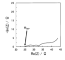
- FIG. 7 is a graph showing a Cole-Cole plot obtained by impedance measurement for the battery of Example 1.
- the vertical axis shows the imaginary part of the complex impedance, and the horizontal axis shows the real part of the complex impedance.
- the real value of the impedance at the measurement point where the absolute value of the phase of the complex impedance was the smallest was regarded as the resistance value R SEP of the solid electrolyte layer of the battery against ion conduction.
- R SEP the resistance value of the solid electrolyte layer of the battery against ion conduction.
- the battery of Example 1 was subjected to constant current discharge at a current value of 16,800 ⁇ A for 10 seconds.
- the DC internal resistance R DC of the electrode was calculated from the voltage change ⁇ V before and after discharge, the current value I, and the resistance value R SEP of the solid electrolyte layer using the following formula (3).
- the DC internal resistance R DC calculated at this time is referred to as "DC internal resistance R DC1 before the charge/discharge cycle.”
- Example 1 was discharged at a constant current of 140 ⁇ A until a voltage of 2.5 V was reached.
- the current value corresponds to a 0.1C rate.
- Example 1 Next, the battery of Example 1 was placed in a constant temperature bath at 60°C.
- the battery of Example 1 was charged with a constant current at a current value of 700 ⁇ A until a voltage of 4.3 V was reached.
- the current value corresponds to a 0.5C rate.
- Example 1 was discharged at a constant current of 2800 ⁇ A until a voltage of 2.5 V was reached.
- the current value corresponds to a 2C rate.
- Example 1 Next, the battery of Example 1 was placed in a constant temperature bath at 25°C.
- the battery of Example 1 was charged with a constant current at a current value of 140 ⁇ A until a voltage of 4.3 V was reached.
- the current value corresponds to a 0.1C rate.
- the battery of the example was discharged at a constant current at a current value of 140 ⁇ A until a voltage of 3.785 V was reached.
- the current value corresponds to a 0.1C rate.
- Example 1 was discharged at a constant voltage at a voltage of 3.785V until a current value of 14 ⁇ A was reached.
- the impedance of the battery of Example 1 was measured by electrochemical impedance measuring method.
- the rate of change in resistance of the battery was calculated by calculating the ratio of the DC internal resistance of the electrode before and after the charge/discharge cycle. Specifically, the ratio of the DC internal resistance R DC2 after the charge/discharge cycle to the DC internal resistance R DC1 before the charge/discharge cycle (R DC2 /R DC1 ) was calculated as the rate of change in resistance of the battery.
- the resistance change rate of the battery of Example 1 was 2.8.
- the resistance change rate of the battery is shown in Table 2.
- Example 2 (Preparation of first solid electrolyte)
- the first solid electrolyte of Example 10 was produced in the same manner as in Example 1 except for the above matters.
- Example 2 the first solid electrolyte of Example 1 was used as the first solid electrolyte.
- the calculated Nb/M2 molar ratio is 0.50, F/X2 molar ratio is 0.02, Li/M2 molar ratio is 0.9, and O/X2 molar ratio is 0. It was .18.
- the calculated Nb/M2 molar ratio is 0.50, F/X2 molar ratio is 0.06, Li/M2 molar ratio is 0.9, and O/X2 molar ratio is 0. It was .18.
- the calculated Nb/M2 molar ratio is 0.80, F/X2 molar ratio is 0.04, Li/M2 molar ratio is 0.9, and O/X2 molar ratio is 0. It was .18.
- the calculated Nb/M2 molar ratio is 0.60, F/X2 molar ratio is 0.04, Li/M2 molar ratio is 0.9, and O/X2 molar ratio is 0. It was .18.
- the calculated Nb/M2 molar ratio is 1.00, F/X2 molar ratio is 0.04, Li/M2 molar ratio is 0.9, and O/X2 molar ratio is 0. It was .18.
- the calculated Nb/M2 molar ratio is 1.00, F/X2 molar ratio is 0.08, Li/M2 molar ratio is 0.9, and O/X2 molar ratio is 0. It was .18.
- the calculated Nb/M2 molar ratio is 1.00, the F/X2 molar ratio is 0.2, the Li/M2 molar ratio is 0.9, and the O/X2 molar ratio is 0. It was .18.
- the calculated Nb/M2 molar ratio is 1.00, F/X2 molar ratio is 0.4, Li/M2 molar ratio is 0.9, and O/X2 molar ratio is 0. It was .18.
- the second solid electrolytes of Examples 2 to 10 were produced in the same manner as in Example 1 except for the above matters.
- the first solid electrolyte of Comparative Example 2 was produced in the same manner as in Example 1 except for the above matters.
- the calculated Nb/M2 molar ratio and F/X2 molar ratio were both 0, Li/M2 molar ratio was 0.9, and O/X2 molar ratio was 0.18. Ta.
- the second solid electrolyte of Reference Example 1 was produced in the same manner as in Example 1 except for the above matters.
- the resistance did not increase even when the green compacts of mixed powder were stored at 60° C. for 48 hours. This is because the reaction between the first solid electrolyte and the second solid electrolyte was suppressed in the mixed powders of Examples 1 to 10, that is, the thermodynamic relationship between the first solid electrolyte and the second solid electrolyte This is thought to mean that the contact stability was high.
- the second solid electrolyte contains F and Nb, the stability of the crystal lattice of the second solid electrolyte is improved. It is presumed that this improves the thermodynamic contact stability between the first solid electrolyte and the second solid electrolyte, and suppresses the formation of a high resistance phase at the interface between the solid electrolytes.
- the second solid electrolyte has higher ionic conductivity. showed degree. This is considered to be because when the Nb/M2 molar ratio is 0.50 or more and 0.80 or less, a path for lithium ions to diffuse into the crystal becomes easier to form.
- the second solid electrolyte is used as a positive electrode material, the ionic conductivity of the positive electrode material becomes higher, so that the charge/discharge characteristics of the battery become higher.
- the second solid electrolyte exhibits even higher ionic conductivity. Ta. This is thought to be because the path for lithium ion diffusion into the crystal is optimized.
- the second solid electrolyte is used as a positive electrode material, the ionic conductivity of the positive electrode material becomes even higher, so that the charge/discharge characteristics of the battery become even higher.
- the second solid electrolyte exhibits higher ionic conductivity. Ta. This is considered to be because a path for lithium ions to diffuse into the crystal becomes easier to form.
- the ionic conductivity of the positive electrode material becomes higher, so that the charge/discharge characteristics of the battery become higher.
- Example 1 in both Example 1 and Comparative Example 1, the first solid electrolyte contained F.
- Example 2 in Example 1 in which the second solid electrolyte contained Nb, the rate of change in battery resistance was smaller than in Comparative Example 1 in which the second solid electrolyte did not contain Nb. That is, the cycle characteristics of the battery were good.
- the presence of F and Nb in the crystal lattice of the second solid electrolyte suppresses the reaction between the first solid electrolyte and the second solid electrolyte, making it difficult to form a high-resistance phase. This is thought to be due to the
- first solid electrolyte and the second solid electrolyte of Examples 1 to 10 do not contain sulfur. Therefore, even when the first solid electrolyte and the second solid electrolyte of Examples 1 to 10 were used as the positive electrode material, hydrogen sulfide was not generated.
- a positive electrode material suitable for improving the charging and discharging characteristics of a battery can be provided.
- the positive electrode material of the present disclosure is used, for example, in a battery (for example, an all-solid lithium ion secondary battery).
- Positive electrode material 101 Positive electrode active material 102 First solid electrolyte 103 Second solid electrolyte 104 Covered active material 105 Second solid electrolyte powder 200 Battery 201 Positive electrode 202 Electrolyte layer 203 Negative electrode 300 Pressure molding die 301 Punch upper part 302 Frame 303 Punch beneath
Landscapes
- Chemical & Material Sciences (AREA)
- Chemical Kinetics & Catalysis (AREA)
- Electrochemistry (AREA)
- General Chemical & Material Sciences (AREA)
- Engineering & Computer Science (AREA)
- Composite Materials (AREA)
- Materials Engineering (AREA)
- Manufacturing & Machinery (AREA)
- Inorganic Chemistry (AREA)
- Condensed Matter Physics & Semiconductors (AREA)
- General Physics & Mathematics (AREA)
- Physics & Mathematics (AREA)
- Battery Electrode And Active Subsutance (AREA)
- Secondary Cells (AREA)
Priority Applications (2)
| Application Number | Priority Date | Filing Date | Title |
|---|---|---|---|
| JP2024514205A JPWO2023195321A1 (https=) | 2022-04-06 | 2023-03-16 | |
| US18/890,833 US20250015291A1 (en) | 2022-04-06 | 2024-09-20 | Positive electrode material and battery containing the same |
Applications Claiming Priority (2)
| Application Number | Priority Date | Filing Date | Title |
|---|---|---|---|
| JP2022-063644 | 2022-04-06 | ||
| JP2022063644 | 2022-04-06 |
Related Child Applications (1)
| Application Number | Title | Priority Date | Filing Date |
|---|---|---|---|
| US18/890,833 Continuation US20250015291A1 (en) | 2022-04-06 | 2024-09-20 | Positive electrode material and battery containing the same |
Publications (1)
| Publication Number | Publication Date |
|---|---|
| WO2023195321A1 true WO2023195321A1 (ja) | 2023-10-12 |
Family
ID=88242708
Family Applications (1)
| Application Number | Title | Priority Date | Filing Date |
|---|---|---|---|
| PCT/JP2023/010402 Ceased WO2023195321A1 (ja) | 2022-04-06 | 2023-03-16 | 正極材料およびそれを用いた電池 |
Country Status (3)
| Country | Link |
|---|---|
| US (1) | US20250015291A1 (https=) |
| JP (1) | JPWO2023195321A1 (https=) |
| WO (1) | WO2023195321A1 (https=) |
Citations (4)
| Publication number | Priority date | Publication date | Assignee | Title |
|---|---|---|---|---|
| WO2020137153A1 (ja) * | 2018-12-28 | 2020-07-02 | パナソニックIpマネジメント株式会社 | 固体電解質材料およびそれを用いた電池 |
| WO2021075243A1 (ja) * | 2019-10-17 | 2021-04-22 | パナソニックIpマネジメント株式会社 | 固体電解質材料およびそれを用いた電池 |
| CN113611834A (zh) * | 2021-07-30 | 2021-11-05 | 蜂巢能源科技有限公司 | 一种三层核壳结构的正极材料、制备方法及电池 |
| WO2022004397A1 (ja) * | 2020-06-29 | 2022-01-06 | パナソニックIpマネジメント株式会社 | 正極材料および電池 |
-
2023
- 2023-03-16 WO PCT/JP2023/010402 patent/WO2023195321A1/ja not_active Ceased
- 2023-03-16 JP JP2024514205A patent/JPWO2023195321A1/ja active Pending
-
2024
- 2024-09-20 US US18/890,833 patent/US20250015291A1/en active Pending
Patent Citations (4)
| Publication number | Priority date | Publication date | Assignee | Title |
|---|---|---|---|---|
| WO2020137153A1 (ja) * | 2018-12-28 | 2020-07-02 | パナソニックIpマネジメント株式会社 | 固体電解質材料およびそれを用いた電池 |
| WO2021075243A1 (ja) * | 2019-10-17 | 2021-04-22 | パナソニックIpマネジメント株式会社 | 固体電解質材料およびそれを用いた電池 |
| WO2022004397A1 (ja) * | 2020-06-29 | 2022-01-06 | パナソニックIpマネジメント株式会社 | 正極材料および電池 |
| CN113611834A (zh) * | 2021-07-30 | 2021-11-05 | 蜂巢能源科技有限公司 | 一种三层核壳结构的正极材料、制备方法及电池 |
Also Published As
| Publication number | Publication date |
|---|---|
| JPWO2023195321A1 (https=) | 2023-10-12 |
| US20250015291A1 (en) | 2025-01-09 |
Similar Documents
| Publication | Publication Date | Title |
|---|---|---|
| JP7752341B2 (ja) | 正極材料および電池 | |
| JP7145439B6 (ja) | 電池 | |
| JP7432897B2 (ja) | 固体電解質材料およびそれを用いた電池 | |
| JPWO2019146236A1 (ja) | 正極材料、および、電池 | |
| WO2021187391A1 (ja) | 正極材料、および、電池 | |
| EP3745503A1 (en) | Positive electrode material and battery using same | |
| JP7486092B2 (ja) | 正極材料、および、電池 | |
| WO2019135322A1 (ja) | 正極材料、および、電池 | |
| WO2021220924A1 (ja) | 正極材料、および、電池 | |
| WO2021157361A1 (ja) | 正極材料および電池 | |
| WO2021161752A1 (ja) | 被覆正極活物質、正極材料、電池、および被覆正極活物質の製造方法 | |
| WO2021205821A1 (ja) | 正極材料および電池 | |
| US20240097131A1 (en) | Coated positive electrode active material, positive electrode material, and battery | |
| WO2022019098A1 (ja) | 正極材料および電池 | |
| CN116529205A (zh) | 固体电解质材料及使用该固体电解质材料的电池 | |
| CN113614948B (zh) | 正极材料和电池 | |
| WO2023032473A1 (ja) | 正極材料および電池 | |
| WO2022215337A1 (ja) | 固体電解質材料およびそれを用いた電池 | |
| US20240136571A1 (en) | Positive electrode material and battery | |
| WO2021220580A1 (ja) | 負極材料および電池 | |
| WO2023195212A1 (ja) | オキシハロゲン化物材料、電池、および電池システム | |
| WO2024029216A1 (ja) | 被覆活物質、正極材料、および電池 | |
| WO2023199629A1 (ja) | 固体電解質材料およびそれを用いた電池 | |
| CN117337497A (zh) | 被覆正极活性物质、正极材料及电池 | |
| CN118556307A (zh) | 电池 |
Legal Events
| Date | Code | Title | Description |
|---|---|---|---|
| 121 | Ep: the epo has been informed by wipo that ep was designated in this application |
Ref document number: 23784611 Country of ref document: EP Kind code of ref document: A1 |
|
| ENP | Entry into the national phase |
Ref document number: 2024514205 Country of ref document: JP Kind code of ref document: A |
|
| NENP | Non-entry into the national phase |
Ref country code: DE |
|
| 122 | Ep: pct application non-entry in european phase |
Ref document number: 23784611 Country of ref document: EP Kind code of ref document: A1 |