WO2023190990A1 - リチウム回収装置およびリチウム回収方法 - Google Patents
リチウム回収装置およびリチウム回収方法 Download PDFInfo
- Publication number
- WO2023190990A1 WO2023190990A1 PCT/JP2023/013395 JP2023013395W WO2023190990A1 WO 2023190990 A1 WO2023190990 A1 WO 2023190990A1 JP 2023013395 W JP2023013395 W JP 2023013395W WO 2023190990 A1 WO2023190990 A1 WO 2023190990A1
- Authority
- WO
- WIPO (PCT)
- Prior art keywords
- lithium
- electrode
- tank
- recovery
- aqueous solution
- Prior art date
- Legal status (The legal status is an assumption and is not a legal conclusion. Google has not performed a legal analysis and makes no representation as to the accuracy of the status listed.)
- Ceased
Links
Images


Classifications
-
- C—CHEMISTRY; METALLURGY
- C02—TREATMENT OF WATER, WASTE WATER, SEWAGE, OR SLUDGE
- C02F—TREATMENT OF WATER, WASTE WATER, SEWAGE, OR SLUDGE
- C02F1/00—Treatment of water, waste water, or sewage
- C02F1/46—Treatment of water, waste water, or sewage by electrochemical methods
- C02F1/469—Treatment of water, waste water, or sewage by electrochemical methods by electrochemical separation, e.g. by electro-osmosis, electrodialysis, electrophoresis
- C02F1/4693—Treatment of water, waste water, or sewage by electrochemical methods by electrochemical separation, e.g. by electro-osmosis, electrodialysis, electrophoresis electrodialysis
-
- C—CHEMISTRY; METALLURGY
- C22—METALLURGY; FERROUS OR NON-FERROUS ALLOYS; TREATMENT OF ALLOYS OR NON-FERROUS METALS
- C22B—PRODUCTION AND REFINING OF METALS; PRETREATMENT OF RAW MATERIALS
- C22B26/00—Obtaining alkali, alkaline earth metals or magnesium
- C22B26/10—Obtaining alkali metals
- C22B26/12—Obtaining lithium
-
- B—PERFORMING OPERATIONS; TRANSPORTING
- B01—PHYSICAL OR CHEMICAL PROCESSES OR APPARATUS IN GENERAL
- B01D—SEPARATION
- B01D61/00—Processes of separation using semi-permeable membranes, e.g. dialysis, osmosis or ultrafiltration; Apparatus, accessories or auxiliary operations specially adapted therefor
- B01D61/42—Electrodialysis; Electro-osmosis ; Electro-ultrafiltration; Membrane capacitive deionization
- B01D61/44—Ion-selective electrodialysis
- B01D61/46—Apparatus therefor
-
- B—PERFORMING OPERATIONS; TRANSPORTING
- B09—DISPOSAL OF SOLID WASTE; RECLAMATION OF CONTAMINATED SOIL
- B09B—DISPOSAL OF SOLID WASTE NOT OTHERWISE PROVIDED FOR
- B09B3/00—Destroying solid waste or transforming solid waste into something useful or harmless
- B09B3/70—Chemical treatment, e.g. pH adjustment or oxidation
-
- B—PERFORMING OPERATIONS; TRANSPORTING
- B09—DISPOSAL OF SOLID WASTE; RECLAMATION OF CONTAMINATED SOIL
- B09B—DISPOSAL OF SOLID WASTE NOT OTHERWISE PROVIDED FOR
- B09B2101/00—Type of solid waste
- B09B2101/15—Electronic waste
- B09B2101/16—Batteries
-
- Y—GENERAL TAGGING OF NEW TECHNOLOGICAL DEVELOPMENTS; GENERAL TAGGING OF CROSS-SECTIONAL TECHNOLOGIES SPANNING OVER SEVERAL SECTIONS OF THE IPC; TECHNICAL SUBJECTS COVERED BY FORMER USPC CROSS-REFERENCE ART COLLECTIONS [XRACs] AND DIGESTS
- Y02—TECHNOLOGIES OR APPLICATIONS FOR MITIGATION OR ADAPTATION AGAINST CLIMATE CHANGE
- Y02W—CLIMATE CHANGE MITIGATION TECHNOLOGIES RELATED TO WASTEWATER TREATMENT OR WASTE MANAGEMENT
- Y02W30/00—Technologies for solid waste management
- Y02W30/50—Reuse, recycling or recovery technologies
- Y02W30/84—Recycling of batteries or fuel cells
Definitions
- the present invention relates to a lithium recovery device and a lithium recovery method that selectively recover lithium ions from an aqueous solution.
- Lithium (Li) is a resource in high demand as a raw material for lithium ion secondary batteries, fuel for nuclear fusion reactors, and the like, and a method for extracting it that can be stably supplied and is cheaper is required.
- Stable sources of Li include seawater dissolved in the form of cationic Li + .
- the positive electrode of lithium ion secondary batteries mainly contains Li in the form of lithium cobalt oxide (LiCoO 2 ), etc., an inexpensive recovery technique for batteries discarded due to battery life is expected.
- Adsorption methods have traditionally been used to recover Li from seawater, etc., but recovery using electrodialysis using an electrolyte membrane with lithium ion conductivity has been developed as a more selective method. (For example, Patent Documents 1 to 5, Non-Patent Document 1).
- the lithium recovery device 101 partitions the processing tank 107 into a supply tank 111 and a recovery tank 112 with a lithium ion conductive electrolyte membrane (hereinafter referred to as an electrolyte membrane) 2, and an electrode 141 in the supply tank 111 and an electrode 142 in the recovery tank 112.
- a power source 151 is connected between the electrodes 141 and 141 as a positive electrode.
- the supply tank 111 is charged with an aqueous solution S0 for Li supply such as seawater as a Li source, and the recovery tank 112 is charged with an aqueous solution S3 for Li recovery such as pure water.
- the lithium ion (Li + ) contained in the electrolyte membrane 2 (electrolyte) is expressed as Li + (electrolyte), and the following formula (2) shows that Li + in the solution moves into the electrolyte membrane 2.
- the following equation (3) shows the reaction in which Li + in the electrolyte membrane 2 moves to the solution.
- the electrolyte membrane 2 Since the size of the lattice defect site is small, the electrolyte membrane 2 does not allow metal ions M n+ other than Li + contained in the Li supplying aqueous solution S0, such as Na + and Ca 2+ , which have a larger diameter than Li + , to pass through. Therefore, Li + is selectively transferred from the Li supply aqueous solution S0 to the Li recovery aqueous solution S3, and an aqueous Li + solution (lithium hydroxide aqueous solution) is obtained in the recovery tank 112.
- metal ions M n+ other than Li + contained in the Li supplying aqueous solution S0 such as Na + and Ca 2+ , which have a larger diameter than Li + , to pass through. Therefore, Li + is selectively transferred from the Li supply aqueous solution S0 to the Li recovery aqueous solution S3, and an aqueous Li + solution (lithium hydroxide aqueous solution) is obtained in the recovery tank 112.
- the electrodes 141 and 142 are provided in contact with the electrolyte membrane 2 (Patent Document 1), and in this case, the aqueous solutions S0 and S3 are It has a porous structure such as a network so as to be in contact with the electrolyte membrane 2.
- the present inventors did not apply the voltage for electrodialysis from both sides of the electrolyte membrane, but from one side of the electrolyte membrane 2 as shown in FIG.
- a technique has been developed to suppress the potential difference between both sides of the electrolyte membrane 2 by forming a circuit using spaced apart electrodes 142 (Patent Document 3). That is, in the lithium recovery apparatus 101 shown in FIG. 18, the electrode 141 or the electrode 142 is arranged apart from the electrolyte membrane 2.
- the present inventors applied a voltage for electrodialysis using porous electrodes that were in contact with both sides of the electrolyte membrane, and also installed an electrode spaced apart from the electrolyte membrane in the recovery tank.
- Patent Document 4 We are developing a technology that can further increase Li + mobility by increasing the voltage for dialysis.
- the Li + mobility is rate-limited by the diffusion of Li + to the surface of the electrolyte membrane, so the Li concentration of the aqueous solution that comes into contact with the surface of the electrolyte membrane on the Li + supply side is low. and is difficult to increase with respect to the applied voltage. Therefore, when seawater or the like with a low Li + concentration is used as a Li source, even with the techniques described in Patent Documents 3 and 4, the Li + mobility becomes low with respect to the applied voltage.
- the present inventors provided an electrode with a porous structure in contact with the electrolyte membrane and an electrode spaced apart from the electrolyte membrane in the supply tank, and thereby created a connection between the electrode with the porous structure and the electrode provided in the recovery tank.
- Li + is brought into the vicinity of the electrolyte membrane in the Li source in the supply tank.
- the minimum voltage (theoretical voltage) required to move Li + in an electrolyte membrane by electrodialysis is as follows: The lower the pH of the aqueous solution, the larger it becomes. Therefore, the lower the pH of the aqueous solution on the Li supply side, the lower the Li + mobility with respect to the applied voltage.
- the waste batteries are crushed in the same way as methods for recovering other metals such as cobalt (Co) and nickel (Ni).
- a solution obtained by roasting and dissolving in a strong acid such as sulfuric acid (H 2 SO 4 ) can be used as an aqueous solution for supplying Li.
- the pH suitable for Li recovery of the Li supplying aqueous solution is 12 to 14, and a large amount of NaOH is required. Since the pH of the aqueous solution for supplying Li is lowered by extracting Li + , which is a cation, from the aqueous solution, it is necessary to continuously add NaOH. In addition, the highly alkaline aqueous solution after Li is extracted needs to be neutralized before being discharged in order to reduce the burden on the environment, which, together with NaOH, increases the cost and makes it difficult to implement industrially. be.
- the solution of the waste battery mentioned above also contains a large amount of cations of metals other than Li, such as Co and aluminum (Al), so along with these metal ions, sulfate ions (SO 4 2- ) and nitrate ions It also contains large amounts of anions such as (NO 3 ⁇ ) and chloride ions (Cl ⁇ ). These anions may be adsorbed to the surface of the electrolyte membrane, which is positively charged by voltage application, and inhibit the movement of Li + .
- the pH decreases due to the reaction of formula (1) to compensate for the charge imbalance in the solution, resulting in an even stronger acid, which causes environmental problems.
- the present invention has been made in view of the above-mentioned problems, and is a lithium recovery method that allows lithium to be safely recovered from discarded lithium ion secondary batteries etc. with high productivity, low cost, and by electrodialysis method.
- An object of the present invention is to provide a method and a lithium recovery device.
- the lithium recovery device includes a treatment tank partitioned into four or more tanks in the following order: one or more acid recovery tanks, one or more lithium supply tanks, one or more alkali recovery tanks, and a lithium recovery tank, and A lithium ion conductive electrolyte membrane partitions the tank into the lithium recovery tank and the alkali recovery tank next to it, and a lithium ion conductive electrolyte membrane partitions the tank into the alkali recovery tank and the alkali recovery tank or the lithium supply tank next to it, one or more ion exchange membranes that conduct at least containing cations; one or more ion exchange membranes that partition the acid recovery tank and the adjacent acid recovery tank or the lithium supply tank and have anion conductivity; Electrodes provided in at least the lithium recovery tank and the acid recovery tank disposed at the opposite end of the treatment tank are connected between the electrodes with the lithium recovery tank side being connected as a negative side.
- one or more power sources for transferring lithium ions contained in the aqueous solution contained in the lithium supply tank to the water or electrolyte contained in the lithium recovery tank, the ion exchange membrane and the lithium ion conductive electrolyte;
- Each of the membranes is arranged between the electrodes connected to both poles of any one of the power sources, and no other electrode is arranged between the electrodes.
- the lithium recovery method in a processing tank partitioned into four or more tanks in the order of one or more acid recovery tanks, one or more lithium supply tanks, one or more alkali recovery tanks, and a lithium recovery tank, the lithium supply tank In this method, lithium ions contained in the aqueous solution contained in the lithium recovery tank are transferred to the water or electrolyte contained in the lithium recovery tank.
- the lithium recovery tank and the alkali recovery tank next to it are separated by a lithium ion conductive electrolyte membrane, and the alkali recovery tank and the alkali recovery tank next to it or the lithium
- the supply tank is partitioned by an ion exchange membrane that conducts cations containing at least lithium ions, and the acid recovery tank and the adjacent acid recovery tank or the lithium supply tank are ion exchange membranes that have anion conductivity.
- One or more power sources connected between electrodes partitioned by a membrane and provided in two or more of the acid recovery tank, the lithium supply tank, the alkali recovery tank, and the lithium recovery tank,
- the lithium recovery tank side applies a voltage that generates a low potential difference between both surfaces of the lithium ion conductive electrolyte membrane and between both surfaces of the ion exchange membrane so that the lithium ion contained in the aqueous solution contained in the lithium supply tank is Lithium ions are transferred to the water or electrolyte contained in the lithium recovery tank via the water or aqueous solution contained in the alkali recovery tank.
- lithium can be recovered not only from seawater but also from waste batteries safely at low cost and with high productivity.
- FIG. 1 is a schematic diagram illustrating the configuration of a lithium recovery device according to a first embodiment of the present invention.
- FIG. 2 is a schematic diagram of the lithium recovery apparatus shown in FIG. 1 illustrating a lithium recovery method according to a first embodiment of the present invention.
- FIG. 2 is a schematic diagram illustrating the configuration of a lithium recovery device and a lithium recovery method according to a first modification of the first embodiment of the present invention.
- 3 is a schematic diagram of the lithium recovery apparatus shown in FIG. 2, illustrating a lithium recovery method according to a first embodiment of the present invention.
- FIG. It is a schematic diagram explaining the composition of the lithium recovery device concerning the 2nd modification of the 1st embodiment of the present invention.
- FIG. 2 is a schematic diagram illustrating the configuration of a lithium recovery device according to a second embodiment of the present invention. It is a schematic diagram explaining the composition of the lithium recovery device concerning a 3rd embodiment of the present invention.
- FIG. 9 is a schematic diagram of the lithium recovery apparatus shown in FIG. 8, illustrating a lithium recovery method according to a third embodiment of the present invention. It is a schematic diagram explaining the composition of the lithium recovery device concerning a 4th embodiment of the present invention.
- FIG. 11 is a schematic diagram of the lithium recovery apparatus shown in FIG. 10 illustrating a lithium recovery method according to a fourth embodiment of the present invention.
- FIG. 7 is a schematic diagram illustrating the configuration of a lithium recovery device and a lithium recovery method according to a modification of the fourth embodiment of the present invention.
- FIG. 2 is a graph showing changes in the amount of cations transferred per hour in terms of lithium ions in an ion exchange membrane in an example according to the present invention.
- FIG. It is a graph showing changes in the amount of lithium recovered per hour in an example according to the present invention. It is a graph showing changes in the amount of lithium recovered per hour in a comparative example. 2 is a graph showing changes in the amount of lithium recovered per hour in Examples and Comparative Examples according to the present invention. 3 is a graph showing changes in temperature in Examples and Comparative Examples according to the present invention.
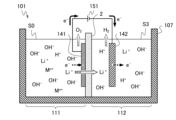
- FIG. 1 is a schematic diagram of a lithium recovery device illustrating a conventional lithium recovery method using electrodialysis.
- the lithium recovery apparatus 1 includes a treatment tank 7, ion exchange membranes 31, 33 that partition the treatment tank 7 into four tanks 11, 12, 13, and 14 in this order. and an electrolyte membrane (lithium ion conductive electrolyte membrane) 2, electrodes 45 and 46 provided in contact with or facing the electrolyte membrane 2 in each of the tanks 13 and 14 partitioned by the electrolyte membrane 2, and electrodes 45 and 46 provided in the tank 11.
- An electrode 41 provided, an electrode 44 provided in the tank 13 apart from the electrode 45, a Li + mobile power source (first power source) 51 connected between the electrodes 45 and 46, and a connection between the electrodes 41 and 44.
- the tank 11 is an acid recovery tank and contains an acid recovery aqueous solution S1.
- the tank 12 is a supply tank (lithium supply tank) and contains an aqueous solution S0 for supplying Li.
- the tank 13 is an alkali recovery tank and contains an aqueous solution S2 for alkali recovery.
- the tank 14 is a Li recovery tank (lithium recovery tank) and contains an aqueous solution S3 for Li recovery.
- the power supplies 51 and 52 are each connected with the Li recovery tank 14 side connected as a negative terminal.
- the Li supplying aqueous solution S0 is a Li source and is an aqueous solution containing lithium ions (Li + ) and other metal ions M n+ .
- Examples of such an aqueous solution include a solution obtained by crushing and roasting a used lithium ion secondary battery and dissolving the resultant in a strong acid such as sulfuric acid (H 2 SO 4 ).
- a strong acid such as sulfuric acid (H 2 SO 4 ).
- the aqueous solution S0 for supplying Li seawater, waste brine after salt is extracted from seawater, underground water such as hot spring water, etc. can be used.
- metal ions M n+ other than Li + include Co 2+ , Fe 2+ , Cu 2+ , Al 3+ , Ni 2+ , etc. , and further contains anions such as sulfate ions (SO 4 2- ), or chloride ions (Cl - ), nitrate ions (NO 3 - ), and fluoride ions (F - ).
- the metal ions M n+ are Na + , K + , Mg 2+ , Ca 2+ , etc.
- the acid recovery aqueous solution S1 contains anions other than hydroxide ions (OH - ) contained in the Li supply aqueous solution S0, especially SO 4 2- , NO 3 - , Cl - , F, which make the aqueous solution a strong acid.
- -It is a solution for accommodating etc.
- the acid recovery aqueous solution S1 is, for example, pure water when the lithium recovery apparatus 1 starts operating.
- the acid recovery aqueous solution S1 may be SO It may also be an acidic aqueous solution in which an anion such as 4 2- is dissolved.
- the alkali recovery aqueous solution S2 is a solution for accommodating cations containing Li + recovered from the Li supply aqueous solution S0, and is a secondary Li source in the lithium recovery apparatus 1.
- the aqueous alkali recovery solution S2 is preferably an aqueous solution that does not contain anions other than OH - , particularly halide ions, and is, for example, pure water at the time of starting the operation of the lithium recovery apparatus 1.
- the alkali recovery aqueous solution S2 may be aqueous so that it has a somewhat high electron conductivity at the start of the operation.
- the alkali recovery aqueous solution S2 is a lithium hydroxide (LiOH) aqueous solution or a sodium hydroxide (NaOH) aqueous solution, and is preferably a LiOH aqueous solution.
- the Li recovery aqueous solution S3 is a solution for accommodating Li + recovered from the Li supply aqueous solution S0.
- the Li recovery aqueous solution S3 is preferably an aqueous solution that does not contain metal ions other than Li + (such as Na + ), and further contains anions other than OH - , especially halogens.
- An aqueous solution that does not contain oxide ions is preferable, and at the time of starting the operation of the lithium recovery apparatus 1, for example, pure water is used.
- the Li recovery aqueous solution S3 is an aqueous solution containing Li + (lithium hydroxide (LiOH) aqueous solution) at the start of operation of the lithium recovery device 1. It is preferable that there be.
- Li + lithium hydroxide (LiOH) aqueous solution
- the electrolyte membrane 2 is an electrolyte that has lithium ion conductivity and does not conduct metal ions M n + other than Li + contained in the Li supplying aqueous solution S0, and preferably does not conduct electrons e - . More preferably, the electrolyte membrane 2 is a ceramic electrolyte having these properties. Specifically, lithium lanthanum titanium oxide (La 2/3-x Li 3x TiO 3 , also referred to as LLTO) may be used. Such an electrolyte membrane 2 has a certain proportion of lattice defects, and since the size of the lattice defect sites is small, metal ions M n+ other than Li + do not conduct because they have a larger diameter than Li + .
- LLTO lithium lanthanum titanium oxide
- the ion exchange membrane 31 that partitions the treatment tank 7 into the acid recovery tank 11 and the supply tank 12 conducts at least one type of anion contained in the Li supply aqueous solution S0, and this anion converts into hydroxide ions (OH - ) It is preferable to contain anions other than ).
- the aqueous solution S0 for supplying Li contains SO 4 2- , NO 3 - , Cl - , F -, etc. that make the aqueous solution a strong acid, it is preferable that the ion exchange membrane 31 conducts these anions. .
- the ion exchange membrane 31 can be an anion exchange membrane that allows anions to pass through and blocks cations. Known anion exchange membranes can be used, such as SELEMION (registered trademark) AMV (manufactured by AGC Engineering Co., Ltd.) and NEOSEPTA ASE (manufactured by Astom Co., Ltd.).
- the ion exchange membrane 31 is selected to correspond to the pH of the Li supplying aqueous solution S0.
- the ion exchange membrane 33 that partitions the treatment tank 7 into the alkali recovery tank 13 and the supply tank 12 conducts cations containing at least Li + . This prevents anions such as SO 4 2- from being contained in the alkali recovery aqueous solution S2 in the alkali recovery tank 13.
- the ion exchange membrane 33 is a cation exchange membrane that allows cations to pass through and blocks anions, and a monovalent cation permselective ion exchange membrane that allows only monovalent cations such as Li + , K + , and Na + to pass through.
- a membrane, a bipolar monovalent ion-selective ion exchange membrane that allows monovalent ions to permeate, etc. can be applied.
- ion exchange membranes can be used as these ion exchange membranes.
- cation exchange membranes SELEMION (registered trademark) CMV, CMVN, CMTE (manufactured by AGC Engineering Co., Ltd.), NEOSEPTA CSE (manufactured by Astom Co., Ltd.) ), SELEMION (registered trademark) CSO (manufactured by AGC Engineering Co., Ltd.) as a monovalent cation permselective ion exchange membrane, CXP-S (manufactured by Astom Co., Ltd.) as a monovalent cation permselective ion exchange membrane, NEOSEPTA as a bipolar type monovalent ion permselective ion exchange membrane CIMS (manufactured by Astom Co., Ltd.) is an example. Since the ion exchange membrane 33 comes into contact with the alkali recovery aqueous solution S2
- the electrodes 41, 44, 45, and 46 are electrodes for applying a voltage between the respective surfaces of the ion exchange membrane 31, the ion exchange membrane 33, and the electrolyte membrane 2 to generate a potential difference that is lower on the Li recovery tank 14 side.
- the lithium recovery device 1 includes electrodes 41 and 46 in at least the tanks 11 and 14 at both ends of the processing tank 7, and further includes electrodes 44 and 45 in the alkali recovery tank 13.
- the electrode 41 and the electrode 44 are connected to an ion transfer power source 52, and the electrode 41 is placed in the acid recovery tank 11 and the electrode 44 is placed in the alkali recovery tank so that the two ion exchange membranes 31 and 33 are sandwiched between them. 13, respectively.
- the electrode (second electrode) 45 and the electrode (first electrode) 46 are connected to a Li + mobile power source 51, and the electrode 45 is connected to the surface of the electrolyte membrane 2 on the supply tank 12 side so that the electrolyte membrane 2 is sandwiched between them.
- electrodes 46 are provided on the surface of the electrolyte membrane 2 on the Li recovery tank 14 side, in contact with or facing each other, and apply a voltage between both surfaces of the electrolyte membrane 2 in a pair. That is, each of the ion exchange membranes 31 and 33 and the electrolyte membrane 2 is arranged between electrodes connected to both poles of any one power source (ion transfer power source 52 or Li + transfer power source 51). Become. It is preferable that the electrodes 41 and 44 and the electrodes 45 and 46 are arranged parallel to each other.
- the electrode 41 is in the acid recovery aqueous solution S1, the electrodes 44 and 45 are in the alkali recovery aqueous solution S2, and the electrode 46 is in the Li recovery aqueous solution S3, including after the operation of the lithium recovery device 1 (after Li recovery), It is made of an electrode material that is stable even when voltage is applied.
- the acid recovery aqueous solution S1 contains sulfuric acid (H 2 SO 4 ), hydrochloric acid ( HCl ), and hydrofluoric acid ( HF), nitric acid (HNO 3 ), etc.
- the alkali recovery aqueous solution S2 becomes a sodium hydroxide (NaOH) aqueous solution or a lithium hydroxide (LiOH) aqueous solution due to Li + and other metal ions M n + contained in the Li supply aqueous solution S0.
- the Li recovery aqueous solution S3 becomes a lithium hydroxide (LiOH) aqueous solution.
- the electrodes 41 and 44 can be arranged apart from the ion exchange membranes 31 and 33, as shown in FIG. can.
- the electrodes 41 and 44 preferably have a shape such as a mesh through which the aqueous solution passes so that the aqueous solutions S1 and S2 that contact the surfaces of the ion exchange membranes 31 and 33 in the tanks 11 and 13 are continuously replaced.
- the electrode 44 is arranged apart from the electrode 45 provided in the same alkali recovery tank 13, and therefore, the distance between the alkali recovery tank 13, that is, the ion exchange membrane 33 and the electrolyte membrane 2, is the same as the partition of the processing tank 7. Design the length to be sufficient in the direction (horizontal direction in Figure 1).
- One or both of the electrodes 45 and 46 preferably have a porous structure and are in contact with the electrolyte membrane 2, and more preferably one is in contact with the electrolyte membrane 2 and the other is spaced apart. More preferably, as shown in FIG. 1, the electrode 45 is provided in contact with the surface of the electrolyte membrane 2 on the supply tank 12 side, that is, in the alkali recovery tank 13, and the electrode 46 is provided in the Li recovery tank 14. It is provided apart from the electrolyte membrane 2. Furthermore, it is preferable that the electrode 46 be arranged parallel to the electrolyte membrane 2.
- the electrode 45 is provided in contact with the electrolyte membrane 2 and applies a voltage to a wide range of the electrolyte membrane 2, while at the same time forming a reticular structure so that the aqueous solution S2 for alkali recovery comes into contact with a sufficient area of the surface of the electrolyte membrane 2. It is preferable to have a porous structure such as.
- the electrode 45 is preferably made of a material that has electron conductivity and has catalytic activity for the reaction of the following formula (1) and the reaction of the following formula (2), and is also formed of a material that can be easily processed into the above shape. It is preferable that The electrode 45 is preferably made of platinum (Pt), for example.
- the electrode 46 is disposed in the Li recovery tank 14 so as not to come into contact with the electrolyte membrane 2, while preferably not having a long distance from the electrolyte membrane 2, and preferably disposed parallel to the electrolyte membrane 2.
- the electrode 46 has a mesh shape or the like through which the aqueous solution passes, so that the contact area with the Li recovery aqueous solution S3 is increased and the Li recovery aqueous solution S3 in contact with the surface of the electrolyte membrane 2 in the Li recovery tank 14 is continuously replaced. It is preferable that the shape is the same.
- the electrode 46 is preferably made of a material that has electron conductivity and catalytic activity for the reaction of the following formula (4), and is preferably formed of a material that can be easily processed into the shape described above.
- the electrode 46 is preferably made of platinum (Pt), for example, or carbon (C), copper (Cu), or nickel (C), which is stable at a potential lower than the potential at which the reaction of formula (4) below occurs.
- Pt platinum
- Ni or stainless steel can also be used, and it is more preferable to have fine particles of Pt supporting the surface thereof which function as a catalyst.
- the Li + mobile power supply (first power supply) 51 and the ion transport power supply 52 are DC power supply devices, and the Li + mobile power supply 51 is connected between the electrodes 45 and 46, and the ion transport power supply 52 is connected between the electrodes 41 and 44. , are connected with the Li recovery tank 14 side as the negative terminal. That is, the Li + mobile power source 51 has a positive electrode connected to the electrode 45 and a negative electrode connected to the electrode 46 .
- the ion movement power source 52 has a positive electrode connected to the electrode 41 and a negative electrode connected to the electrode 44 .
- the Li + transfer power source 51 applies a voltage V1 between both surfaces of the electrolyte membrane 2 to generate a potential gradient for causing the electrolyte membrane 2 to conduct Li + .
- the ion transfer power source 52 applies a voltage V2 to the two ion exchange membranes 31 and 33 together to form a potential difference between both surfaces of the ion exchange membranes 31 and 33, where the Li recovery tank 14 side is lower.
- the anions contained in the Li supply aqueous solution S0 are transferred to the acid recovery aqueous solution S1, and the metal ions contained in the Li supply aqueous solution S0 are transferred to the alkali recovery aqueous solution S2.
- a constant current source to the Li + transfer power source 51 and the ion transfer power source 52, the movement of Li + in the electrolyte membrane 2 and the movement of anions and cations in the ion exchange membranes 31 and 33 can be suppressed. For each, the amount of movement per time can be maintained constant.
- the treatment tank 7 is made of a material that does not undergo deterioration such as corrosion even when it comes into contact with the Li supplying aqueous solution S0 and the aqueous solutions S1, S2, and S3, including after the operation of the lithium recovery device 1 (after Li recovery).
- the Li recovery aqueous solution S3 becomes a lithium hydroxide (LiOH) aqueous solution.
- the processing tank 7 only needs to have a volume corresponding to the required processing capacity, and its shape etc. are not particularly limited.
- the circulation device 81 is a device that circulates the acid recovery aqueous solution S1 in the acid recovery tank 11 so as to keep replacing it during operation, and is a device that circulates the acid recovery aqueous solution S1 in the acid recovery tank 11, and connects the circulation tank provided outside the processing tank 7, and the inside of the tank and the acid recovery tank.
- a pump is provided to circulate the acid recovery aqueous solution S1 between the inside of the tank 11 and the acid recovery aqueous solution S1. That is, the circulation device 81 is not limited in its configuration as long as it is arranged so that the liquid in the circulation tank can be circulated or supplied by a pump via a circulation path such as a pipe communicating with the acid recovery tank 11.
- the circulation device 81 is shown below the acid recovery tank 11, but this is a schematic example and the arrangement is not specified (the other circulation devices 82, 83, 84 are also similar). ). Furthermore, the circulation device 81 recovers the acid in the acid recovery tank 11 by compensating for a decrease in the amount of liquid in the acid recovery tank 11 as needed, and by replacing the acid recovery aqueous solution S1 with pure water or the like. Lowering of pH (strong oxidation) of the aqueous solution S1 can be suppressed. Similarly, the circulation device 82 is a device that circulates the Li supply aqueous solution S0 in the supply tank 12 so that it is continuously replaced.
- the circulation devices 83 and 84 are devices that circulate the aqueous solutions S2 and S3 so that they are continuously replaced in the tanks 13 and 14, and so that the aqueous solutions S2 and S3 that are in contact with the electrodes 45 and 46 and the electrolyte membrane 2 are continuously replaced.
- the circulation device 83 may include a precipitation tank for precipitating metal ions M n+ other than Li +
- the circulation device 84 may include a precipitation tank for precipitating Li +
- a filter for preventing the precipitate from returning to the tanks 13 and 14. good.
- the circulation device 83 preferably recovers the hydroxides of metal ions M n + other than Na + because they precipitate in the aqueous alkali recovery solution S2.
- the precipitation tank of the circulation device 84 generates and precipitates lithium carbonate (Li 2 CO 3 ) by, for example, carbon dioxide gas (CO 2 ) bubbling.
- a known stirrer equipped with a screw that rotates in each tank can be applied, and each can be configured as necessary.
- the circulation device 82 may have a structure open to the sea instead of having a circulation tank.
- the lithium recovery device 1 may further include a heating device that heats the electrolyte membrane 2 via the Li recovery aqueous solution S3 or the alkali recovery aqueous solution S2 in order to bring the electrolyte membrane 2 to a predetermined temperature.
- the heating device may be a known heater that heats a liquid, and preferably has a temperature adjustment function.
- the heating device is, for example, an immersion type (immersion type) installed by being immersed in the Li recovery aqueous solution S3 in the Li recovery tank 14 or the alkali recovery aqueous solution S2 in the alkali recovery tank 13.
- immersion type installed by being immersed in the Li recovery aqueous solution S3 in the Li recovery tank 14 or the alkali recovery aqueous solution S2 in the alkali recovery tank 13.
- the aqueous solution in the circulation tank of the circulation device 83 or 84 may be heated.
- the heating device only needs to be able to bring the electrolyte membrane 2 to a predetermined temperature, and it is not necessary to keep the aqueous solution S3 for Li recovery and the aqueous solution S2 for alkali recovery at a uniform temperature.
- the liquid temperature of the alkali recovery aqueous solution S2 is the applicable temperature range of the ion exchange membrane 33.
- the temperature of the electrolyte membrane 2 may be at least the freezing point or lower than the boiling point of the aqueous solutions S3 and S2, and is preferably a high temperature as described later.
- the lithium recovery device 1 may further include a liquid level sensor or the like in order to sense fluctuations in the amounts of the aqueous solutions S0, S1, S2, and S3 during operation. Additionally, if carbon dioxide (CO 2 ) in the atmosphere unintentionally dissolves in the alkali recovery aqueous solution S2 or the Li recovery aqueous solution S3 during operation, and lithium carbonate (Li 2 CO 3 ) or the like precipitates, the aqueous solution S2 , S3 undesirably decreases in conductivity. To prevent this, the lithium recovery apparatus 1 is preferably configured so that the aqueous solutions S2 and S3 are not exposed to the atmosphere.
- O 2 and H 2 are generated by the reactions of formulas (1) and (3), and the lithium recovery device 1 is equipped with an exhaust means to exhaust these gases so as not to fill the inside. It is preferable for safety. Furthermore, if the Li supply aqueous solution S0 contains chloride ions (Cl - ), chlorine (Cl 2 ) may be generated (see modified example below), and this can also be recovered as a by-product. .
- the lithium recovery device 1 exhausts the gas generated from the aqueous solutions S0, S1, S2, and S3 to the outside of the processing tank 7, and prevents outside air from flowing into the tanks 11, 12, and 13 of the processing tank 7, for example. , 14 is preferably provided with a check valve. In the lithium recovery device 1, O 2 and Cl 2 can be recovered from the acid recovery tank 11, O 2 and H 2 from the alkali recovery tank 13, and H 2 from the Li recovery tank 14.
- the tanks 11, 12, 13, and 14 of the processing tank 7 are arranged in a straight line, but two electrodes 44, connected to different power sources 51, 52, respectively.
- the alkali recovery tank 13 provided with the alkali recovery tank 45 may have a structure bent by 90 degrees, for example.
- the ion exchange membrane 33 and the electrolyte membrane 2 are arranged perpendicularly to each other to partition the alkali recovery tank 13, and the electrodes 44 and 45 are also arranged perpendicularly to each other.
- the lithium recovery method according to the first embodiment of the present invention will be described with reference to FIG. 2.
- the lithium recovery method according to the present embodiment is performed as follows using the lithium recovery apparatus 1 according to the first embodiment shown in FIG. Note that in FIG. 2, the circulation devices 81 to 84 are omitted.
- the Li + mobile power source 51 applies a positive voltage V1 (+V1) to the electrode 45 with respect to the electrode 46 .
- the ion movement power source 52 applies a positive voltage V2 (+V2) to the electrode 41 with respect to the electrode 44.
- V1 (+V1
- V2 (+V2
- anions such as SO 4 2- , NO 3 - , Cl - in the aqueous solution S0 for Li supply in the supply tank 12 pass through the ion exchange membrane 31 and pass through the ion exchange membrane 31 to the acid recovery tank 11 for acid recovery.
- aqueous solution S1 anions such as SO 4 2- , NO 3 - , Cl - in the aqueous solution S0 for Li supply in the supply tank 12 pass through the ion exchange membrane 31 and pass through the ion exchange membrane 31 to the acid recovery tank 11 for acid recovery. Move to aqueous solution S1.
- the following reaction occurs in the alkali recovery aqueous solution S2 by applying the voltage +V1.
- hydroxide ions (OH - ) in the aqueous solution S2 for alkali recovery cause the reaction of the following formula (1) to generate water (H 2 O) and oxygen (O 2 ). , to emit electrons e ⁇ to the electrode 45.
- the reaction of the following formula (2) in which Li + in the alkali recovery aqueous solution S2 moves into the electrolyte membrane 2 is carried out. , occurs on the surface of the electrolyte membrane 2, that is, near the electrode 45.
- the reaction of the following formula (1) and the reaction of the following formula (2) are combined to produce the reaction of the following formula (5).
- the following reaction occurs upon application of the voltage +V1.
- H 2 O in the Li recovery aqueous solution S3 is supplied with electrons e - to cause the reaction of formula (4) below to generate hydrogen (H 2 ) and OH - .
- Li + in the electrolyte membrane 2 moves to the aqueous solution for Li recovery S3 in order to maintain charge balance. occurs.
- the reaction of the following formula (3) and the reaction of the following formula (4) are combined to produce the reaction of the following formula (6).
- the reaction of formula (1) and the reaction of formula (4) occur, and Li + becomes an electrolyte. It moves in the membrane 2.
- the voltage at which the water electrolysis reaction occurs is +1.229V (25°C) when the alkali recovery aqueous solution S2 and the Li recovery aqueous solution S3 have the same pH (hydrogen ion concentration).
- the voltage V1 needs to be set to a value several hundred mV larger than the theoretical voltage of 1.229V, depending on the electrode performance that determines each electrode reaction overvoltage.
- Li + in the Li supply aqueous solution S0 is transferred to the alkali recovery aqueous solution S2 by permeating the ion exchange membrane 33 together with other cations, and then transferred to the alkali recovery aqueous solution S2. move.
- the Li supply aqueous solution S0 since not only cations containing Li + but also anions such as SO 4 2 are extracted from the Li supply aqueous solution S0, the Li supply aqueous solution S0 does not become a strong acid during operation of the lithium recovery device 1. , can drive safely.
- the reaction amounts of the reaction of formula (1) and the reaction of formula (4) increase, and accordingly, the reaction of formula (2) and the reaction of formula (3) become faster.
- the potential gradient between both surfaces thereof increases, and the amount of movement of Li + per time (Li + mobility) increases.
- the potential difference between both sides of the electrolyte membrane 2 is higher than the voltage at which some of the metal ions constituting the electrolyte membrane 2 are reduced (for example, if the electrolyte membrane 2 is LLTO, Ti 4+ +e - ⁇ Ti 3+ ). Then, the electrolyte membrane 2 will conduct electrons e - from the Li recovery tank 14 side to the alkali recovery tank 13 side.
- Patent Document 3 As a result, most of the given electrical energy is consumed in the conduction of electrons e - , so the voltage dependence of Li + mobility decreases, and the energy efficiency in Li + movement decreases rapidly (Patent Document 3). reference). In particular, such a phenomenon is likely to occur with transition metal ions among the metal ions constituting the electrolyte membrane 2.
- one of the electrodes 45 and 46, here the electrode 46 is arranged apart from the electrolyte membrane 2, so that the voltage between both surfaces of the electrolyte membrane 2 with respect to the voltage V1 is The potential difference is kept small, and the electrolyte membrane 2 hardly exhibits electronic conductivity (see Patent Document 3).
- the voltage V1 is increased beyond a certain level, the potential difference between both sides of the electrolyte membrane 2 reaches a potential difference that causes the electrolyte membrane 2 to exhibit electron conductivity, so it is preferable to set the voltage V1 below such a voltage.
- the relationship between the voltage V1 and the potential difference between both surfaces of the electrolyte membrane 2 depends on the distance between the electrode 46 and the electrolyte membrane 2 and the electronic conductivity of the Li recovery aqueous solution S3.
- the electronic conductivity of the Li recovery aqueous solution S3 increases, and the potential difference between both surfaces of the electrolyte membrane 2 increases to the voltage V1. It gets bigger as it approaches. Therefore, it is preferable to set the voltage V1 in consideration of the electronic conductivity of the Li recovery aqueous solution S3 during operation.
- the rate of Li + mobility is determined by the diffusion of Li + to the supply side surface of the electrolyte membrane, so if the Li + concentration of the aqueous solution on the supply side is low, the electrolyte membrane Even if the applied voltage (V1) between both sides is increased, the Li + mobility is difficult to increase. Therefore, if the alkali recovery aqueous solution S2 is pure water or has a low Li + concentration at the start of operation, only the voltage +V2 is applied by the ion transfer power source 52 immediately after the start of operation to remove a certain amount of Li. From the viewpoint of energy efficiency, it is preferable to start applying the voltage +V1 by the Li + mobile power source 51 after + is contained in the aqueous solution for alkali recovery S2.
- the amount of movement per hour increases.
- the Li + concentration of the alkali recovery aqueous solution S2 decreases, and the rate of Li + mobility from the alkali recovery aqueous solution S2 to the Li recovery aqueous solution S3 is determined.
- the voltage V2 it is preferable to set the voltage V2 so that the Li + mobility (in the electrolyte membrane 2) from the aqueous solution for alkali recovery S2 to the aqueous solution for Li recovery S3 is not rate-determining.
- the electric field generated by the application of voltage V2 increases as the distance between the electrode 41 and the ion exchange membrane 31 and the distance between the electrode 44 and the ion exchange membrane 33 decrease, and the electron conductivity of the aqueous solutions S1 and S2 increases.
- the amount of Li + transferred per hour from the aqueous solution S0 for supplying Li to the aqueous solution S2 for alkali recovery is smaller than the amount transferred (Li + mobility) in the electrolyte membrane 2, the amount of Li + in the aqueous solution S2 for alkali recovery is
- the concentration decreases to below a predetermined concentration the Li + transfer power source 51 may be stopped and only the ion transfer power source 52 may be driven until a sufficient amount of Li + is transferred from the Li supply aqueous solution S0. good.
- the ion transfer power source 52 may be stopped and only the Li + transfer power source 51 may be driven. Therefore, for example, the Li + moving power source 51 and the ion moving power source 52 can be driven alternately for respective predetermined periods.
- the temperature of the electrolyte membrane 2 is high. Furthermore, the higher the temperature of the aqueous solutions S2 and S3, the lower the resistance.
- the applicable temperature range of the electrolyte membrane 2 is above the freezing point and below the boiling point of the aqueous solutions S2 and S3, preferably above 20°C.
- the lithium recovery device 1 includes two power sources 51 and 52, and applies voltages (V1, V2) between both surfaces of the electrolyte membrane 2 and between each of the ion exchange membranes 31 and 33. can be set individually. Therefore, both the voltage for moving Li + in the electrolyte membrane 2 and the voltage for moving cations and anions containing Li + from the Li supplying aqueous solution S0 to the aqueous solutions S2 and S1 are set to appropriate levels. Can be set to . Further, as described above, only one of the power supplies 51 and 52 can be driven as necessary.
- the lithium recovery device 1 applies a voltage V2 with electrodes 41 and 44 disposed on both sides of the ion exchange membranes 31 and 33 that partition the supply tank 12 containing the Li supply aqueous solution S0 on both sides.
- V2 voltage V2 with electrodes 41 and 44 disposed on both sides of the ion exchange membranes 31 and 33 that partition the supply tank 12 containing the Li supply aqueous solution S0 on both sides.
- anions and cations with the same valence are extracted from the Li supply aqueous solution S0. Therefore, during operation, the pH of the Li supply aqueous solution S0 is difficult to change, and precipitation of metal ions in the Li supply aqueous solution S0 is suppressed.
- the Li supply aqueous solution S0 does not contain anions other than hydroxide ions, specifically, anions that the ion exchange membrane 31 conducts, water is not transferred from the Li supply aqueous solution S0 to the acid recovery aqueous solution S1. Only oxide ions move. In the acid recovery aqueous solution S1, the hydroxide ions that have moved are consumed by the reaction of formula (1) near the electrode 41, so the amount of anions does not change, and therefore the pH does not change.
- An example of such an aqueous solution S0 for supplying Li is an aqueous solution obtained by dissolving crushed and roasted waste batteries in water.
- the circulation devices 82, 83, 84, 81 are activated by the liquid level sensor detecting the liquid level or by the set time of the timer, and the circulation devices 82, 83, 84, 81 are activated periodically or constantly to It is preferable to supplement each aqueous solution or its solvent (pure water). In the lithium recovery apparatus 1, it is preferable that the liquid levels of the tanks 11, 12, 13, and 14 are even during operation.
- Li recovery aqueous solution S3 in the Li recovery tank 14 and the circulation tank of the circulation device 84 is treated with carbon dioxide gas (CO 2 ) Li can be recovered by producing lithium carbonate (Li 2 CO 3 ) by bubbling or the like and causing it to precipitate.
- lithium carbonate Li 2 CO 3
- lithium hydroxide LiOH
- Li + may be precipitated as lithium carbonate or the like in a precipitation tank of the circulation device 84.
- metal ions other than Li + M n+ can be recovered by known methods depending on the type. Note that, as described above, most of the metal ions M n + other than Na + generate hydroxides and precipitate. Further, the acid recovery aqueous solution S1 in the acid recovery tank 11 and the circulation tank of the circulation device 81 can be reused, for example, as an acid for dissolving roasted waste batteries.
- the alkali recovery aqueous solution S2 in the alkali recovery tank 13 contains only monovalent cations such as Li + , Na + , and K + .
- the divalent and trivalent cations such as Co 2+ , Mg 2+ , and Al 3+ remain in the aqueous solution S0 for supplying Li. Therefore, the amount of precipitates in the alkali recovery aqueous solution S2 that comes into contact with the supply side surface of the electrolyte membrane 2 can be reduced, and the movement of Li + from the alkali recovery aqueous solution S2 to the Li recovery aqueous solution S3 is inhibited. Not done. Further, the circulation device 83 can recover monovalent cations other than Li + . On the other hand, the polyvalent cations remaining in the Li supplying aqueous solution S0 can be recovered by the circulation device 82.
- the solution S3 for accommodating Li + is not limited to an aqueous solution, and a general liquid electrolyte used in lithium ion secondary batteries can also be applied. Specifically, using LiPF 6 , LiClO 4 , LiBF 4 , LiN(CF 3 SO 2 ) 2 , LiN(C 2 F 5 SO 2 ) 2, etc. as electrolytes, ethylene carbonate, propylene carbonate, ⁇ -butyrolactane, dimethyl carbonate, etc. , diethyl carbonate, ethyl methyl carbonate, 1,2-dimethoxyethane, acetonitrile, and other organic solvents.
- LiPF 6 , LiClO 4 , LiBF 4 , LiN(CF 3 SO 2 ) 2 , LiN(C 2 F 5 SO 2 ) 2, etc. as electrolytes, ethylene carbonate, propylene carbonate, ⁇ -butyrolactane, dimethyl carbonate, etc. , diethyl carbonate, ethy
- the lithium recovery device In the lithium recovery device according to the embodiment, two power sources are used to form a potential difference between both surfaces of the two ion exchange membranes and between both surfaces of the electrolyte membrane. It is also possible to form a potential difference by using two ion exchange membranes and two electrolyte membranes.
- a lithium recovery device and a lithium recovery method according to a modification of the first embodiment of the present invention will be described with reference to FIGS. 3 to 6.
- the lithium recovery apparatus 1A according to the first modification of the first embodiment of the present invention has a processing tank 7, and the processing tank 7 is partitioned into four tanks 11, 12, 13, and 14 in this order.
- electrode 46A provided in contact with electrolyte membrane 2 in Li recovery tank 14
- electrode 41 provided in acid recovery tank 11
- a circulation device (circulation tank and circulation means) 81 provided for each tank 11, 12, 13, and 14.
- the lithium recovery device 1A according to this modification is different from the lithium recovery device 1 according to the embodiment shown in FIG. This is a configuration in which electrodes 41 and 46A arranged at 2 are connected to each other.
- the electrode 41 and the electrode 46A are provided in the acid recovery tank 11 and the electrode 46A in the Li recovery tank 14, respectively, so that the ion exchange membranes 31, 33 and the electrolyte membrane 2 are sandwiched between them. With this configuration, the pair of electrodes 41 and 46A can apply a voltage between the respective surfaces of the ion exchange membrane 31, the ion exchange membrane 33, and the electrolyte membrane 2 to generate a potential difference that is lower on the Li recovery tank 14 side. Can be done. It is preferable that the electrode 41 and the electrode 46A are arranged parallel to each other.
- the electrode 41 can have the same configuration as the embodiment described above, and is preferably made of a material that has catalytic activity for the reaction of the following formula (1).
- the electrode (first electrode) 46A is brought into contact with the surface on the Li recovery tank 14 side. establish.
- the electrode 46A has a porous structure, such as a net shape, like the electrode (second electrode) 45 of the embodiment described above.
- the electrode 46A is preferably made of a material that has a catalytic activity for the reaction of the following formula (4) like the electrode 46 of the embodiment described above, and further has a catalytic activity for the reaction of the following formula (3).
- the electrode 46A is preferably made of, for example, Pt as such an electrode material.
- the power supply 51 is connected between the electrodes 41 and 46A with the Li recovery tank 14 side, that is, the electrode 46A, as a negative electrode.
- the power supply 51 applies a voltage V1 to the ion exchange membranes 31, 33 and the electrolyte membrane 2 all at once to form a potential difference between both surfaces of the ion exchange membranes 31, 33 and the electrolyte membrane 2, where the Li recovery tank 14 side is lower. .
- This potential difference causes the anions contained in the aqueous solution S0 for Li supply to be transferred to the aqueous solution S1 for acid recovery, and the metal ions contained in the aqueous solution S0 for Li supply to be transferred to the aqueous solution S2 for alkali recovery, and the electrolyte membrane 2 to generate a potential gradient for conducting Li + .
- a lithium recovery method according to a modification of the first embodiment of the present invention will be described with reference to FIG. 4. Note that in FIG. 4, the circulation devices 81 to 84 are omitted.
- the lithium recovery method according to the present modification can be performed in the same manner as the lithium recovery method according to the first embodiment using a lithium recovery apparatus 1A according to the modification of the first embodiment shown in FIG.
- the power supply 51 applies a positive voltage V1 (+V1) to the electrode 41 with respect to the electrode 46A. Then, in the vicinity of the electrode 41, the hydroxide ions (OH - ) in the acid recovery aqueous solution S1 cause the reaction of the following formula (1) to generate H 2 O and O 2 , which are transferred to the electrode 41. Release electron e - . Furthermore, when the Li supplying aqueous solution S0 contains chloride ions (Cl - ), the reaction of the following formula (7) occurs to generate chlorine (Cl 2 ).
- H 2 O in the Li recovery aqueous solution S3 is supplied with electrons e - to cause the reaction of the following formula (4), and H 2 and OH - are generated, and as OH - increases, in order to maintain the charge balance, the reaction of formula (3) below is carried out in which Li + in the electrolyte membrane 2 moves to the Li recovery aqueous solution S3. arise.
- Li can be selectively recovered by the lithium recovery device 1A, which includes one power source 51 and a pair of electrodes 41 and 46A connected to both electrodes thereof, similarly to the embodiment described above.
- the lithium recovery device 1A the number of parts is reduced, and unlike the alkali recovery tank 13 of the lithium recovery device 1, there is no need to arrange two electrodes spaced apart from each other in the same tank. can be shortened in the partition direction.
- the lithium recovery apparatus 1B according to the second modified example of the first embodiment of the present invention has four processing tanks 7, and four processing tanks 11, 12, 13, and 14 in the order of tanks 11, 12, 13, 14. ion exchange membranes 31, 33 and electrolyte membrane (lithium ion conductive electrolyte membrane) 2, and electrodes provided in contact with or facing the electrolyte membrane 2 in each tank 13, 14 partitioned by the electrolyte membrane 2.
- a lithium recovery device 1B according to this modification example is different from the lithium recovery device 1 according to the embodiment shown in FIG. This configuration includes ion movement power sources 53 and 52 that individually apply voltages between both surfaces.
- the electrodes 41, 42, 43, 44, 45, and 46 are used to apply a voltage between the respective surfaces of the ion exchange membrane 31, the ion exchange membrane 33, and the electrolyte membrane 2 to generate a potential difference that is lower on the Li recovery tank 14 side.
- the electrode 41 and the electrode 42 are provided in the acid recovery tank 11 and the supply tank 12, respectively, so that the ion exchange membrane 31 is sandwiched between the electrodes 41 and 42.
- the electrode 43 and the electrode 44 are provided in the supply tank 12 and the electrode 44 in the alkali recovery tank 13, respectively, with the ion exchange membrane 33 sandwiched between them.
- the electrode 45 and the electrode 46 are in contact with the surface of the electrolyte membrane 2 on the alkali recovery tank 13 side so as to sandwich the electrolyte membrane 2 therebetween, and the electrode 46 is in contact with the surface of the electrolyte membrane 2 on the alkali recovery tank 13 side. It is provided facing the surface of the membrane 2 on the Li recovery tank 14 side.
- the electrodes 41 and 42, the electrodes 43 and 44, and the electrodes 45 and 46 are arranged parallel to each other.
- the electrodes 41, 44, 45, and 46 can each have the same configuration as in the embodiment described above.
- the electrodes 42 and 43 are formed of an electrode material that is stable even when a voltage is applied in the Li supplying aqueous solution S0, including after the operation of the lithium recovery device 1B (after Li recovery). Further, like the electrodes 41 and 44, the electrodes 42 and 43 can be arranged apart from the ion exchange membranes 31 and 33 as shown in FIG. It is preferable that the shape is a mesh-like shape through which the aqueous solution passes so that the aqueous solution S0 for supplying Li is continuously replaced.
- the electrode 42 and the electrode 43 are arranged apart from each other like the electrodes 44 and 45, and therefore, the interval between the supply tank 12, that is, the ion exchange membrane 31 and the ion exchange membrane 33 is in the partition direction of the processing tank 7 ( The length should be sufficient in the horizontal direction (in the left-right direction in Fig. 5).
- the ion transfer power source 52 has a positive electrode connected to the electrode 43 and a negative electrode connected to the electrode 44.
- the ion movement power source 53 is a DC power source like the ion movement power source 52, and has a positive electrode connected to the electrode 41 and a negative electrode connected to the electrode 42.
- the lithium recovery method using the lithium recovery apparatus 1B according to this modification can be performed in the same manner as the lithium recovery method according to the embodiment (see FIG. 2).
- the voltages applied between both surfaces of the ion exchange membrane 31 and between both surfaces of the ion exchange membrane 33 can be individually set. Therefore, the voltages for moving cations containing Li + from the Li supply aqueous solution S0 to the alkali recovery aqueous solution S2 and anions to the acid recovery aqueous solution S1 can both be set to appropriate levels.
- only one of the power supplies 52 and 53 can be driven to move only cations or anions, making it easy to manage the pH of the Li supply aqueous solution S0 during operation.
- the lithium recovery device 1B according to this modification can have a structure in which the alkali recovery tank 13 is bent, similar to the lithium recovery device 1 according to the embodiment. Further, the lithium recovery device 1B can have a structure in which the ion exchange membrane 31 and the ion exchange membrane 33 are arranged perpendicularly to each other, and the supply tank 12 is also bent.
- the electrode 42 and the electrode 43 provided in the supply tank 12 can also be integrated. That is, as shown in FIG. 6, the lithium recovery device 1C according to the third modification of the first embodiment of the present invention is different from the lithium recovery device 1B in that the electrode 43 is integrated with the electrode 42, and the electrode 42 is , the positive electrode of the power source 52 is connected to the negative electrode of the power source 53, and therefore the power source 53 and the power source 52 are connected in series. In the lithium recovery apparatus 1C, it is preferable that the power source 52 and the power source 53 are floating power sources.
- the lithium recovery device 1C can individually set the voltage applied between both surfaces of the ion exchange membranes 31 and 33, as well as reduce the number of parts. Since there is no need to arrange two electrodes at a sufficient interval in the supply tank 12 as in the lithium recovery device 1B, the processing tank 7 can be shortened in the partition direction.
- the electrode 44 provided in the alkali recovery tank 13 and the second electrode 45 can also be integrated.
- the electrode 44 may be integrated with the second electrode 45 that is in contact with the surface of the electrolyte membrane 2 on the supply tank 12 side, and in this case, as described in the fourth embodiment below, the electrode 44 may be connected in series.
- the voltages V2 and V1 of the power source 52 and the power source 51 are set in an appropriate relationship.
- the lithium recovery apparatus 1D partitions the processing tank 7 into six tanks 11b, 11a, 12, 13a, 13b, and 14 in this order.
- the ion exchange membranes 32, 31, 33, 34 and the electrolyte membrane (lithium ion conductive electrolyte membrane) 2 are provided in contact with or opposite the electrolyte membrane 2 in each of the tanks 13b and 14 partitioned by the electrolyte membrane 2.
- the electrodes 45 and 46 are acid recovery tanks similar to the tank 11 of the lithium recovery device 1 according to the first embodiment, and contain acid recovery aqueous solutions S1b and S1a, respectively.
- the tank 13b is an alkali recovery tank that accommodates the aqueous solution S2 for alkali recovery, similar to the tank 13 of the lithium recovery device 1 according to the first embodiment.
- the tank 13a is a primary alkali recovery tank (alkali recovery tank) at a stage before the alkali recovery tank 13b, and accommodates the alkali recovery aqueous solution S2'.
- the lithium recovery apparatus 1D according to the present embodiment has ion exchange membranes 32 and 34 added to the lithium recovery apparatus 1 according to the first embodiment shown in FIG. 1, and has two acid recovery tanks and two alkali recovery tanks.
- the structure consists of tanks arranged side by side.
- the ion exchange membrane 32 is provided on the acid recovery tank 11b side of the supply tank 12, conducts at least one kind of anion contained in the Li supply aqueous solution S0, and conducts at least one type of anion contained in the Li supply aqueous solution S0. , preferably contains anions other than hydroxide ions (OH ⁇ ), and preferably contains anions that the ion exchange membrane 31 conducts.
- the ion exchange membrane 32 is provided on the opposite side of the supply tank 12 to the ion exchange membrane 31, and partitions the processing tank 7 into a tank 11b and a tank 11a.
- the ion exchange membrane 32 arranged in this manner can be one compatible with neutral to acidic properties.
- the ion exchange membrane 32 is preferably an ion exchange membrane that is selectively permeable to monovalent anions, a bipolar type ion exchange membrane that is selectively permeable to monovalent ions, or the like.
- the ion exchange membrane 34 is provided on the alkali recovery tank 13b side of the supply tank 12, and conducts cations containing at least Li + .
- the ion exchange membrane 34 is provided on the opposite side of the supply tank 12 to the ion exchange membrane 33, and partitions the processing tank 7 into a tank 13a and a tank 13b.
- the same ion exchange membrane as the ion exchange membrane 33 can be applied.
- a cation exchange membrane that conducts cations containing multivalent ions is applied to one of the ion exchange membranes 33 and 34, and a monovalent cation permselective ion exchange membrane or a bipolar monovalent ion permselective membrane is applied to the other.
- An ion exchange membrane may also be applied.
- the lithium recovery method using the lithium recovery apparatus 1D according to the present embodiment can be performed in the same manner as the lithium recovery method according to the first embodiment (see FIG. 2).
- the lithium recovery device 1D by providing the plurality of ion exchange membranes 33 and 34 that conduct cations on the Li recovery tank 14 side of the supply tank 12, anions can be further shielded from the Li supply aqueous solution S0. , the alkali recovery aqueous solution S2 that contacts the Li + supply side surface of the electrolyte membrane 2 can be made to have a higher pH.
- the acid recovery tank 11a and the circulation tank of its circulation device 81a can be SO 4 2- can be recovered, that is, the acid recovery aqueous solution S1a can be recovered as sulfuric acid.
- Monovalent anions such as NO 3 - , Cl - , F - can be recovered in each of the acid recovery tank 11b and the circulation tank of the circulation device 81b.
- monovalent cation permselective ion exchange membranes and bipolar monovalent ion permselective ion exchange membranes have sufficient resistance to strong alkalinity. Many do not have this.
- the alkali recovery aqueous solution S2 that contacts the Li + supply side surface of the electrolyte membrane 2 preferably has a high pH.
- a monovalent ion selectively permeable ion exchange membrane is applied to the ion exchange membrane 33 in the lithium recovery device 1D. do.
- the pH of the alkali recovery aqueous solution S2' is adjusted to a predetermined value or less by, for example, recovering monovalent cations other than Li + using the circulation device 83a.
- an acid is added to the alkali recovery aqueous solution S2' in advance to prevent the pH from becoming high.
- the acid added to the alkali recovery aqueous solution S2' should not precipitate Li + and can be selected from the same acid as that contained in the Li supply aqueous solution S0, such as nitric acid, sulfuric acid, hydrochloric acid, etc.
- the amount of precipitate can be reduced in the alkali recovery aqueous solution S2 that contacts the supply side surface of the electrolyte membrane 2 by applying a monovalent ion selectively permeable ion exchange membrane that does not have high alkali resistance. This prevents the movement of Li + to the aqueous solution S3 for Li recovery from being inhibited, and increases the pH, thereby making it possible to further increase the mobility of Li + .
- the ion exchange membrane 33 is a cation exchange membrane that conducts cations including multivalent ions
- the ion exchange membrane 34 is an ion exchange membrane that is permselective for monovalent ions. You can also.
- polyvalent ions among the cations contained in the Li supply aqueous solution S0 can be recovered from the alkali recovery aqueous solution S2' in the primary alkali recovery tank 13a by the circulation device 83a.
- three ion exchange membranes are arranged on the Li recovery tank 14 side of the supply tank 12 in the following order: a cation exchange membrane, a monovalent ion permselective ion exchange membrane, and a cation exchange membrane.
- three alkali recovery tanks may be provided.
- An acid is added to the aqueous solution in each of the first and second alkali recovery tanks from the supply side to prevent it from becoming strongly alkaline.
- the pH of the aqueous solution that contacts the electrolyte membrane 2 of the third alkali recovery tank can be increased, and the polyvalent cations among the ions contained in the Li supplying aqueous solution S0 can be increased. does not remain unbalanced, and can suppress the formation of precipitates and large changes in pH.
- only polyvalent cations can be precipitated and recovered from the aqueous solution in the first alkali recovery tank.
- two power sources are used to form a potential difference between each of the four ion exchange membranes and between both sides of the electrolyte membrane.
- four ion exchange membranes and an electrolyte membrane may be used together, or one or two to three ion exchange membranes may be used. It is also possible to form a potential difference between each sheet.
- the lithium recovery device In the lithium recovery device according to the first embodiment, it is preferable to suppress the voltage applied between both surfaces of the lithium ion conductive electrolyte membrane so that the potential difference is such that the lithium ion conductive electrolyte membrane does not exhibit electronic conductivity. Therefore, the following configuration was adopted in order to increase the voltage and increase the Li + mobility while preventing the lithium ion conductive electrolyte membrane from exhibiting electron conductivity.
- a lithium recovery device and a lithium recovery method according to a third embodiment of the present invention will be described with reference to FIGS. 8 and 9.
- the lithium recovery device 1E includes a treatment tank 7, ion exchange membranes 31, 33 that partition the treatment tank 7 into four tanks 11, 12, 13, and 14 in this order. and an electrolyte membrane (lithium ion conductive electrolyte membrane) 2, electrodes 45 and 46A provided in contact with the electrolyte membrane 2 in each tank 13 and 14 partitioned by the electrolyte membrane 2, and an acid recovery tank 11.
- An electrode 41 provided in the alkali recovery tank 13, an electrode 44 provided spaced apart from the second electrode 45, and a sub-electrode 47 provided in the Li recovery tank 14 spaced apart from the electrolyte membrane 2 and the first electrode 46A.
- the lithium recovery device 1E is different from the lithium recovery device 1 according to the first embodiment shown in FIG.
- a first electrode 46A is provided in the Li recovery tank 14 in contact with the electrolyte membrane 2, , a configuration in which a first electrode 46A, a sub-electrode 47 spaced apart from the electrolyte membrane 2, and a sub-power source 54 connected between the electrodes 46A and 47 are added in the Li recovery tank 14.
- the first electrode 46A is an electrode for applying a voltage between both surfaces of the electrolyte membrane 2 in a pair with the second electrode 45, and is also an electrode on the Li recovery tank 14 side of the electrolyte membrane 2 in the Li recovery aqueous solution S3. This is an electrode that increases the potential of the surface relatively.
- the first electrode 46A has a porous structure and is provided in contact with the surface of the electrolyte membrane 2 on the Li recovery tank 14 side.
- the first electrode 46A has electron conductivity and is in the Li recovery aqueous solution S3.
- the first electrode 46A is preferably made of, for example, platinum (Pt) as such an electrode material.
- the auxiliary electrode 47 is an electrode for forming a lower potential than the surface of the electrolyte membrane 2 in the Li recovery aqueous solution S3, and is an electrode for applying a voltage in pair with the second electrode 45. Therefore, the sub-electrode 47 is arranged in the Li recovery tank 14 so as not to contact the electrolyte membrane 2 and the first electrode 46A, facing the first electrode 46A, and arranged in parallel with the first electrode 46A. It is preferable. Furthermore, as will be described later, it is preferable that the sub-electrode 47 be disposed close to the first electrode 46A to the extent that it does not short-circuit.
- the sub-electrode 47 has a shape such as a mesh shape so as to increase the contact area with the Li recovery aqueous solution S3.
- the sub-electrode 47 is preferably formed of an electrode material that has electron conductivity and is stable even when a voltage is applied in the Li recovery aqueous solution S3, and further has catalytic activity for the reaction of the following formula (4). Therefore, the sub-electrode 47 can have the same configuration as the first electrode 46 of the lithium recovery device 1 according to the first embodiment.
- the auxiliary power source 54 is a DC power source like the Li + mobile power source 51 , and has a positive electrode connected to the first electrode 46A and a negative electrode connected to the auxiliary electrode 47 , that is, in series with the negative electrode of the Li + mobile power source 51 . Connecting.
- the auxiliary power supply 54 applies a voltage V4 to form a lower potential in the Li recovery aqueous solution S3 than the surface of the electrolyte membrane 2, thereby suppressing development of electronic conductivity of the electrolyte membrane 2.
- Lithium recovery method A lithium recovery method according to a third embodiment of the present invention will be described with reference to FIG. 9.
- the lithium recovery method according to the present embodiment is performed as follows using the lithium recovery apparatus 1E according to the third embodiment shown in FIG. Note that in FIG. 9, the circulation devices 81 to 84 are omitted.
- the voltage V1 is applied by the Li + mobile power source 51 and the voltage V4 is applied by the sub power source 54 at the same time.
- the voltage V2 is applied by the ion transfer power source 52, and the anions and cations in the Li supplying aqueous solution S0 are transferred to the aqueous solution S1.
- S2 and after a certain amount of Li + is contained in the alkali recovery aqueous solution S2, it is preferable to start applying the voltages V1 and V4.
- the Li + mobile power source 51 and the sub power source 54 connected in series can be considered as one power source (referred to as power sources 51-54).
- the power supplies 51-54 apply a positive voltage (V1+V4) to the second electrode 45 with respect to the sub-electrode 47. Then, the reaction of the following formula (1) occurs in the vicinity of the second electrode 45, and the reaction of the following formula (2) in which Li + in the aqueous alkali recovery solution S2 moves into the electrolyte membrane 2 is caused. This occurs near the two electrodes 45, that is, the surface of the electrolyte membrane 2.
- the following reaction occurs in the Li recovery tank 14 in which the first electrode 46A and the sub-electrode 47 are arranged.
- the sub power supply 54 applies a positive voltage V4 of a predetermined magnitude based on the voltage V1 to the first electrode 46A and the sub electrode 47.
- a potential gradient is generated in the Li recovery aqueous solution S3, with the potential gradient being positive near the first electrode 46A and negative near the sub-electrode 47.
- the electrons e - supplied from the sub-electrode 47 to the Li recovery aqueous solution S3 move from the first electrode 46A on the surface of the electrolyte membrane 2 to the positive electrode of the sub-power supply 54, and move from the first electrode 46A, that is, the surface of the electrolyte membrane 2
- the potential is maintained as high as the O 2 generation potential.
- the electrolyte membrane 2 Since the O 2 generation potential is higher than the reduction potential of the metal ions constituting the electrolyte membrane 2 (if the electrolyte membrane 2 is LLTO, Ti 4+ +e - ⁇ Ti 3+ ), the electrolyte membrane 2 It does not conduct electron e - . Therefore, the voltage V1 can be set to a voltage higher than the applied voltage that causes the electrolyte membrane 2 to reach the reduction potential of at least one kind of metal ion constituting the electrolyte membrane 2. In other words, if such a large voltage V1 is applied without applying the voltage V4, the metal ions will be reduced by taking in electrons e - from the negative electrode side (Li recovery tank 14 side) of the electrolyte membrane 2. Become.
- the electrolyte membrane 2 does not reach the reduction potential of metal ions, and the electrolyte membrane 2 does not transmit electrons e.sup.- .
- the electrolyte membrane 2 does not transmit electrons e.sup.- .
- the Li recovery aqueous solution S3 Li + is attracted to the vicinity of the sub-electrode 47 due to the potential gradient, and the Li + concentration near the surface of the electrolyte membrane 2 decreases.
- a large chemical potential difference is generated between both surfaces of the electrolyte membrane 2 due to the Li + concentration gradient, so that the movement of Li + between lattice defect sites in the electrolyte membrane 2 is promoted.
- the movement of Li + in the electrolyte membrane 2 becomes faster as the potential gradient in the electrolyte membrane 2 becomes larger, that is, the voltage V1 of the Li + movement power source 51 becomes larger. Also, as described above, the movement of Li + in the electrolyte membrane 2 becomes faster as the Li + concentration gradient in the electrolyte membrane 2 becomes larger. Therefore, the stronger the electric field E4 between the first electrode 46A and the sub-electrode 47 in the Li recovery aqueous solution S3, that is, the larger the voltage V4 of the sub-power supply 54, the easier the reaction of formula (3) becomes, and can be transferred to the Li recovery aqueous solution S3 at high speed.
- the reaction 3) becomes faster, and Li + in the electrolyte membrane 2 can be transferred to the Li recovery aqueous solution AS.
- the voltage V4 is set to such a value that current does not flow from the first electrode 46A toward the negative electrode of the Li + mobile power source 51.
- the lithium recovery device according to the embodiment described above is similar to the lithium recovery devices 1B and 1C (see FIGS. 5 and 6) according to the second and third modified examples of the first embodiment, in which each ion exchange membrane is may be provided with an ion transfer power source that applies a voltage between both surfaces thereof. Further, like the lithium recovery device 1D according to the second embodiment (see FIG. 7), the lithium recovery device includes two or more ion exchange membranes that conduct anions and two or more ion exchange membranes that conduct cations. You can.
- Lithium recovery from used lithium ion secondary batteries and the like requires a recovery rate closer to 100%.
- the alkali recovery aqueous solution on the supply side of the electrolyte membrane decreases.
- the amount of Li + transferred decreases, and the Li + concentration of the aqueous solution for alkali recovery decreases, resulting in a decrease in the Li + mobility in the electrolyte membrane, regardless of the voltage applied between both sides of the electrolyte membrane.
- the lithium recovery apparatus 1F includes a treatment tank 7, ion exchange membranes 31, 33 that partition the treatment tank 7 into four tanks 11, 12, 13, and 14 in this order. and an electrolyte membrane (lithium ion conductive electrolyte membrane) 2; in each tank 13, 14 partitioned by the electrolyte membrane 2, a second electrode 45 provided in contact with the electrolyte membrane 2; A first electrode 46 provided in the acid recovery tank 11 , an electrode 41 provided in the acid recovery tank 11 , an electrode 42 provided facing the ion exchange membrane 31 in the supply tank 12 , and an electrode 42 separated from the electrode 42 and connected to the ion exchange membrane 33 Electrodes 43 provided opposite to each other, a Li + moving power source 51 connected between the electrodes 45 and 46, an ion moving power source 52 connected between the electrodes 43 and 45, and ions connected between the electrodes 41 and 42 A mobile power source 53 and circulation devices (circulation tanks and circulation means) 81, 82
- the power supplies 51, 52, and 53 are each connected with the Li recovery tank 14 side connected as a negative terminal.
- the lithium recovery device 1F according to the present embodiment is different from the lithium recovery device 1 according to the first embodiment shown in FIG. It is configured to be integrated with the electrode 45, add electrodes 42 and 43 in the supply tank 12, and include power sources 53 and 52 for ion movement that individually apply voltage between both surfaces of the ion exchange membranes 31 and 33. .
- the lithium recovery device 1F has a configuration in which the electrode 44 is integrated with the second electrode 45, compared to the lithium recovery device 1B according to the second modification of the first embodiment shown in FIG.
- Each element of the lithium recovery apparatus 1F according to the present embodiment can have the same configuration as the elements of the lithium recovery apparatus 1, 1B according to the first embodiment and its modification.
- the electrode 43 is further paired with the second electrode 45 to apply a voltage to generate a potential difference between both surfaces of the ion exchange membrane 33, and the alkali recovery aqueous solution S2 in the alkali recovery tank 13.
- the second electrode 45 ie, the surface of the electrolyte membrane 2 is provided to form a lower potential gradient than the supply tank 12 side where the electrode 43 is disposed. It is preferable that the electrode 43 and the second electrode 45 are arranged parallel to each other, and the distance between them is preferably shorter.
- Lithium recovery method A lithium recovery method according to a fourth embodiment of the present invention will be described with reference to FIG. 11.
- the lithium recovery method according to the present embodiment is performed as follows using the lithium recovery apparatus 1F according to the fourth embodiment shown in FIG. Note that in FIG. 11, the circulation devices 81 to 84 are omitted.
- the voltage V1 when the voltage V1 is applied by the Li + transfer power source 51, the voltage V2 is simultaneously applied by the ion transfer power source 52.
- the ion transfer power sources 52, 53 or only the ion transfer power source 52 are driven to obtain a certain amount of Li from the aqueous solution S0. It is preferable to start applying the voltage V1 after moving Li + to the aqueous alkali recovery solution S2.
- the ion transfer power source 52 and the Li + transfer power source 51 connected in series can be considered as one power source (referred to as power sources 52-51).
- the power source 52-51 applies a positive voltage (V2+V1) to the electrode 43 with respect to the first electrode 46.
- the Li + mobile power source 51 applies a positive voltage V1 to the second electrode 45 with respect to the first electrode 46 .
- OH - in the aqueous solution S0 for supplying Li causes the reaction of the following formula (1) to generate H 2 O and O 2 and release electrons e - to the electrode 43.
- the reaction of the following formula (7) further occurs near the electrode 43 to generate Cl 2 .
- cations such as Li + and M n+ move to the alkali recovery aqueous solution S2 in order to maintain charge balance.
- OH - in the alkali recovery aqueous solution S2 causes the reaction of the following formula (1) to generate H 2 O and O 2 . Electrons e - are emitted to the second electrode 45.
- H 2 O in the Li recovery aqueous solution S3 is supplied with electrons e - to cause the reaction of the following formula (4), As H 2 and OH - are generated and OH - increases, Li + in the electrolyte membrane 2 moves to the Li recovery aqueous solution S3 in order to maintain charge balance. produce a reaction.
- a potential gradient is formed in which the second electrode 45, that is, the surface of the electrolyte membrane 2 has a lower potential than the supply tank 12 side.
- Li + which is a cation, is attracted to the surface of the electrolyte membrane 2 by electrostatic attraction, and its concentration becomes relatively high in this vicinity. Therefore, even if the Li + concentration of the alkali recovery aqueous solution S2 is low, Li + can sufficiently diffuse to the surface of the electrolyte membrane 2.
- a large Li + concentration gradient is formed between both surfaces of the electrolyte membrane 2 compared to the Li + concentration of the aqueous solution for alkali recovery S2, resulting in a large chemical potential difference. Mobility is encouraged.
- the voltage V1 can be set similarly to the first embodiment.
- the reaction of the following formula (4) occurs in the alkali recovery aqueous solution S2 near the second electrode 45. This will generate H2 .
- the second electrode 45 since the second electrode 45 receives the electron e - , the movement of the electron e - is in the opposite direction to the reaction of the formula (1) below in the vicinity of the second electrode 45 shown in FIG.
- the second electrode 45 that is, the surface of the electrolyte membrane 2 on the supply tank 12 side reaches the potential of H 2 generated, the metal ions constituting the electrolyte membrane 2 become reaches a potential at which the electrolyte membrane 2 is reduced, and the electrolyte membrane 2 exhibits electron conductivity.
- the energy efficiency in transferring Li + in the electrolyte membrane 2 is sharply reduced.
- the voltage V2 is set to be less than the voltage at which H 2 is generated near the second electrode 45 (see Patent Document 5).
- the voltage at which H 2 is generated is actually a standard value, depending on the electrode performance that determines the electrode reaction overvoltage of each electrode (for voltage V2, electrodes 43 and 45), the pH of the solution near both electrodes, etc.
- the value is about the theoretical voltage for electrolysis of water (1.229 V, 25° C.) or several hundred mV larger than that.
- the voltage V1 is larger than the voltage V2 by a certain degree, the potential of the surface of the electrolyte membrane 2 on the supply tank 12 side (high potential side) becomes H. 2 , and H 2 is not generated.
- the voltage V2 exceeds a certain level with respect to the potential difference between both surfaces of the electrolyte membrane 2, a current flows from the second electrode 45 to the negative electrode of the ion transfer power source 52, that is, the second electrode 45 becomes an electron e - , and the reaction of formula (4) occurs nearby to generate H 2 .
- the electrolyte membrane 2 exhibits electronic conductivity. Therefore, it is preferable that the voltage V2 is large enough to prevent current from flowing from the second electrode 45 toward the negative electrode of the ion transfer power source 52.
- an ammeter is connected in series with the second electrode 45 (an ammeter is connected between the connection part of the ion transfer power source 52 and Li + transfer power source 51 and the second electrode 45).
- the voltages V1 and V2 may be applied while measuring the current (see Patent Document 5).
- the lithium recovery device Similar to the third embodiment, the lithium recovery device according to the above embodiment has the second electrode and the first electrode in contact with both surfaces of the electrolyte membrane, and a sub power source is connected to the negative electrode of the Li + transfer power source connected between them.
- a sub-electrode in the Li recovery tank that is connected in series and connected to the negative electrode of the sub-power supply, it is possible to increase the potential difference between both sides of the electrolyte membrane and increase the Li + mobility in the electrolyte membrane.
- a lithium recovery device 1G includes a treatment tank 7, an ion exchange membrane that partitions the treatment tank 7 into four tanks 11, 12, 13, and 14 in this order. 31, 33, an electrolyte membrane (lithium ion conductive electrolyte membrane) 2, electrodes 45, 46A provided in contact with the electrolyte membrane 2 in each tank 13, 14 partitioned by the electrolyte membrane 2, and an acid recovery tank.
- a treatment tank 7 an ion exchange membrane that partitions the treatment tank 7 into four tanks 11, 12, 13, and 14 in this order. 31, 33
- an electrolyte membrane lithium ion conductive electrolyte membrane
- electrodes 45, 46A provided in contact with the electrolyte membrane 2 in each tank 13, 14 partitioned by the electrolyte membrane 2
- an acid recovery tank an acid recovery tank.
- the lithium recovery device 1G further includes circulation devices (circulation tanks and circulation means) 81, 82, 83, and 84 provided for each of the tanks 11, 12, 13, and 14 (see FIG. 10).
- the power supplies 51, 52, and 53 are each connected with the Li recovery tank 14 side connected as a negative terminal.
- the lithium recovery device 1G according to this modification has a Li recovery tank similar to the lithium recovery device 1E according to the third embodiment shown in FIG.
- a first electrode 46A is provided in the Li recovery tank 14 in contact with the electrolyte membrane 2, and a sub-electrode 47 spaced apart from the first electrode 46A and the electrolyte membrane 2 is provided in the Li recovery tank 14, and a sub-electrode 47 connected between the electrodes 46A and 47 is provided in the Li recovery tank 14.
- the ion transfer power source 52 and the auxiliary power source 54 simultaneously apply the voltages V2 and V4.
- the ion transfer power sources 52, 53 or only the ion transfer power source 52 are driven to obtain a certain amount of Li from the Li supply aqueous solution S0. It is preferable to start applying the voltages V1 and V4 after moving + to the aqueous alkali recovery solution S2.
- the ion transfer power source 52, Li + transfer power source 51, and sub power source 54 connected in series can be considered as one power source (referred to as power source 52-51-54).
- the Li + mobile power source 51 and the sub power source 54 can be considered as one power source (referred to as power sources 51-54).
- the power supply 52-51-54 applies a positive voltage (V2+V1+V4) to the electrode 43 with respect to the sub-electrode 47.
- the power supplies 51-54 apply a positive voltage (V1+V4) to the second electrode 45 with respect to the sub-electrode 47.
- the reaction of the following formula (1) occurs near each of the electrode 43 and the second electrode 45, and OH - in the aqueous solutions S0 and S2 becomes H 2 O and O 2 to occur.
- the reaction of the following formula (7) further occurs near the electrode 43 to generate Cl 2 .
- the reaction of formula (2) below occurs in the vicinity of the second electrode 45, that is, the surface of the electrolyte membrane 2, in which OH - decreases in the alkali recovery aqueous solution S2 and Li + moves into the electrolyte membrane 2.
- the following reaction occurs as in the third embodiment.
- the voltage (V1+V4) is applied by the power sources 51-54, electrons e - are supplied to H 2 O in the Li recovery aqueous solution S3, so that the reaction of the following formula (4) occurs, and H 2 and OH - to occur.
- the sub power supply 54 applies a positive voltage V4 to the first electrode 46A with respect to the sub electrode 47, so that the OH - in the Li recovery aqueous solution S3 is lowered in the vicinity of the first electrode 46A.
- the reaction of formula (1) occurs, electrons e - are released to the first electrode 46A, and H 2 O and O 2 are generated.
- Combining the reaction of the following formula (4) and the reaction of the following formula (1) increases OH - , so in order to maintain the charge balance, the following formula (3) in which Li + in the electrolyte membrane 2 moves ) reaction occurs on the surface of the electrolyte membrane 2, that is, in the vicinity of the first electrode 46A.
- Li + quickly moves from the vicinity of the first electrode 46A to the vicinity of the sub-electrode 47.
- the voltage V2 is set based on the voltages V1 and V3, as will be described later.
- Li + in the aqueous solution for alkali recovery S2 becomes relatively high in concentration near the surface of the electrolyte membrane 2 due to the application of the voltage V2. + Even if the concentration is low, Li + can sufficiently diffuse to the surface of the electrolyte membrane 2. Furthermore, as in the third embodiment, by applying the voltage V4, the potential on the surface of the electrolyte membrane 2 is maintained as high as the O 2 generation potential, and the electrolyte membrane 2 is able to hold electrons e - regardless of the potential difference between both surfaces, that is, the voltage V1 .
- Li + is attracted to the vicinity of the sub-electrode 47 in the Li recovery aqueous solution S3, and the Li + concentration near the surface of the electrolyte membrane 2 decreases. Therefore, a large Li + concentration gradient is formed between both surfaces of the electrolyte membrane 2 compared to the Li + concentration of the alkali recovery aqueous solution S2, and a large chemical potential difference occurs. Mobility is encouraged.
- the voltage V1 can be set to a large voltage similarly to the third embodiment.
- the voltage V2 should be less than the voltage at which H 2 is generated in the vicinity of the second electrode 45 and the first electrode 46A, and it is preferable that the voltage be larger within this range in order to increase the Li recovery rate.
- the lithium recovery apparatus may not include the electrodes 42 and 43 and the ion transfer power source 53, and the positive electrode of the ion transfer power source 52 may be connected to the electrode 41.
- the ion exchange membrane 31 and the ion exchange membrane 33, and the ion exchange membrane 33 and the electrolyte membrane 2 that is, the supply tank 12 and the alkali recovery tank 13, are preferably shorter in the partitioning direction of the processing tank 7 (left and right directions in FIGS. 10 and 12), and the electrode 41 is arranged closer to the ion exchange membrane 31.
- the lithium recovery device includes two or more ion exchange membranes that conduct anions and two or more ion exchange membranes that conduct cations. It's okay.
- the lithium recovery device uses a plate-shaped La 0.57 Li 0.29 TiO 3 (lithium ion conductive ceramics LLTO, manufactured by Toho Titanium Co., Ltd.) with a size of 50 mm x 50 mm and a thickness of 0.5 mm as an electrolyte membrane (number 2 in FIG. 8). It was used. 19 lattice-shaped electrodes with a thickness of 10 ⁇ m, a width of 0.5 mm, and an interval of 0.5 mm are placed at the center of each of both sides of this electrolyte membrane as a first electrode and a second electrode (numerals 46A and 45 in FIG. 8). A lead wire for connecting to a power source was formed to be connected to the electrode.
- La 0.57 Li 0.29 TiO 3 lithium ion conductive ceramics LLTO, manufactured by Toho Titanium Co., Ltd.
- the first electrode, second electrode, and lead wire were formed by screen printing Pt paste on the surface of the electrolyte membrane and baking it at 900° C. for 1 hour in the atmosphere.
- an anion exchange membrane NOSEPTA ASE, manufactured by Astom Co., Ltd., number 31 in Figure 8
- CXP-S monovalent cation permselective cation exchange membrane
- an electrolyte membrane on which electrodes and the like were formed were arranged and installed in this order to divide the tank into four tanks.
- a 20 mm x 20 mm Pt mesh electrode (41 in FIG. 8) was placed in an acid recovery tank (11 in FIG.
- a 20 mm x 20 mm Pt mesh electrode (code 44 in Figure 8) was placed in an alkali recovery tank (code 13 in Figure 8) separated by a cation exchange membrane and an electrolyte membrane so as to directly face the cation exchange membrane. Placed.
- a 20 mm x 20 mm Ni mesh electrode was placed as an auxiliary electrode (numeral 47 in Fig. 8) in the Li recovery tank (numeral 14 in Fig. 8) on the first electrode side separated by the electrolyte membrane, directly connected to the electrode on the surface of the electrolyte membrane.
- a Li + mobile power source (reference numeral 51 in FIG. 8) is connected with the second electrode as the positive electrode, and a sub power source (reference numeral 54 in FIG. 8) is connected to the negative electrode of the first power source.
- a sub power source (reference numeral 54 in FIG. 8) is connected to the negative electrode of the first power source.
- an ion transfer power source (numeral 52 in Figure 8) was connected between the Pt mesh electrode in the acid recovery tank and the Pt mesh electrode in the alkali recovery tank, with the acid recovery tank side as the positive electrode, and a lithium recovery device was constructed. .
- an ammeter was inserted between the positive electrode and the second electrode of the Li + transfer power source, and between the negative electrode of the ion transfer power source and the Pt mesh electrode in the alkali recovery tank.
- Li supply aqueous solutions Two types of aqueous solutions containing Li + and other various ions and having different pHs were prepared as Li supply aqueous solutions (Li sources).
- the neutral aqueous solution for supplying Li contains a large amount of nitric acid and does not contain Al 3+ because it precipitates.
- 150 ml of the Li supply aqueous solution was put into the supply tank of the lithium recovery device.
- 2000 ml of the same Li supply aqueous solution was placed in a circulation tank of a circulation device for Li supply aqueous solution installed outside the processing tank of the lithium recovery device.
- aqueous solution for Li recovery a 0.1 mol/L lithium hydroxide (LiOH) aqueous solution was prepared, and 150 ml of the solution was poured into the Li recovery tank of the lithium recovery device so that the first electrode and the sub-electrode were completely immersed.
- aqueous solution for acid recovery and an aqueous solution for alkali recovery 150 ml of pure water was poured into the acid recovery tank and the alkali recovery tank so that the electrodes were completely immersed, respectively.
- Lithium recovery experiment As an example according to the third embodiment of the present invention (see FIG. 9), first, a DC voltage of 8 V (voltage V2 in FIG. 9) was applied using an ion transfer power source. In order to suppress changes in the ion concentration in the supply tank due to electrodialysis, the aqueous solution for Li supply is replenished from the replenishment tank into the supply tank at a constant rate using a liquid feed pump, and pumped out at the same rate while applying a voltage. Ta. For each of the alkaline (pH 12) and neutral (pH 7) Li supply aqueous solutions, the current value (I2) measured with an ammeter connected to the ion transfer power source and the cations that transferred this current value are all Li + FIG.
- FIG. 13 shows the transition of the amount of movement per hour up to 20 hours. Then, 48 hours after the start of application of voltage V2 by the ion transfer power source, while continuing to apply voltage V2, a DC voltage of 5 V is applied to the Li + transfer power source and 10 V is applied to the auxiliary power source (voltages V1 and V4 in FIG. 9). started applying.
- the alkali recovery aqueous solution in the alkali recovery tank became an aqueous solution of monovalent metal ion hydroxides (LiOH, NaOH, KOH) due to voltage application by the ion transfer power source, and after 48 hours of voltage application, i.e.
- LiOH, NaOH, KOH monovalent metal ion hydroxides
- the Li + concentration was 1.0 mol/L and the pH was about 11.
- the acid recovery aqueous solution in the acid recovery tank became an acid containing all types of anions (see Table 1) contained in the Li supply aqueous solution after 48 hours of voltage application.
- FIG. 14 shows the current value (I1) measured with an ammeter connected to the Li + mobile power supply and the transition of the amount of movement per time when this current value is converted as Li + moved.
- the amount of movement of Li + per time was calculated by current x time x Li atomic weight/Faraday constant.
- the Li atomic weight was 6.941 g/mol, and the Faraday constant was 96485 C/mol.
- a processing tank made of acrylic plate was divided into two tanks by an electrolyte membrane having the same first and second electrodes as in the example, and the second electrode side was a supply tank and the first electrode side was a Li recovery tank. And so.
- the same sub-electrode as in the example was placed in the Li recovery tank, a Li + mobile power source was connected between the first electrode and the second electrode with the second electrode as the positive electrode, and the sub-power source was connected to the negative electrode of the first power source. They were connected in series and the negative electrode was connected to the sub-electrode to form a lithium recovery device. Furthermore, an ammeter was inserted between the positive electrode and the second electrode of the Li + mobile power source.
- the same Li supply aqueous solution as in the example was charged into the supply tank of the lithium recovery device according to the comparative example, and the same 0.1 mol/L LiOH aqueous solution as in the example was charged into the Li recovery tank. While circulating the aqueous solution in the supply tank as in the example, a DC voltage of 5 V was applied from the Li + mobile power source and 10 V from the auxiliary power source. For each of the alkaline (pH 12) and neutral (pH 7) Li supply aqueous solutions, the current value (I1) was measured with an ammeter connected to a Li + mobile power source, and this current value was converted as Li + transferred.
- FIG. 15 shows the change in the amount of movement per hour.
- the amount of cations moved per hour is small immediately after the start of application of voltage V2 by the ion transfer power source, and then gradually increases over time. It leveled off after 10 to 12 hours. This is because, at the start of application, the contents of the acid recovery tank and the alkali recovery tank were pure water, so the electrical conductivity was low. Further, the amount of cation movement (current) was larger in the neutral Li supplying aqueous solution. This is presumably because the alkaline Li supplying aqueous solution had fewer anions passing through the anion exchange membrane, so the current flowing was also smaller.
- the voltage from the power supply for Li + transfer and the sub-power supply is Application of V1 and V4 was started.
- the Li + mobility rose sharply after about 40 minutes had passed from the start of application of the voltages V1 and V4, and then gradually increased with a high Li + mobility. This is presumed to be because the temperature of the electrolyte membrane was about 20° C. before the application of the voltages V1 and V4 started, but the temperature of the electrolyte membrane rose to about 40° C. with the application of the voltage V1.
- Li + The mobility was nearly four orders of magnitude lower than that of the example, and further decreased as the application time progressed. This is because anions in the Li supply aqueous solution are adsorbed to the surface of the electrolyte membrane, which is positively charged by the application of voltage V1, inhibiting the movement of Li + , and the amount of adsorption increases as the application time progresses. It is presumed that the Li + mobility gradually decreased as a result.
- the Li + mobility of the neutral Li supplying aqueous solution was about 1/20 as low as that of the alkaline Li supplying aqueous solution. Furthermore, in the comparative example, the temperature of the electrolyte membrane hardly changed because the aqueous solution for supplying Li, which was in contact with the supply side surface of the electrolyte membrane, was circulated within the supply tank and in the external circulation tank.
- the lithium recovery device according to the comparative example used in Experiment 1 was used with the supply tank simulating the alkali recovery tank of the example.
- an aqueous solution for Li supply (alkaline) was put into the supply tank, and the aqueous solution recovered in the alkaline recovery tank after 48 hr of voltage application by the ion transfer power source had a Li + concentration of 0.2 mol/L.
- the solution was diluted with pure water to give an aqueous solution for alkali recovery.
- This aqueous alkali recovery solution had a pH of about 12.
- FIG. 16 shows the current value (I1) measured with an ammeter connected to the Li + mobile power supply and the transition of the amount of movement per time when this current value is converted as the moved Li + .
- FIG. 17 shows the change in temperature of the alkali recovery aqueous solution measured with a thermometer installed in the supply tank.
- the Li + mobility increased approximately in proportion to the voltage application time. It is presumed that this change in Li + mobility is accompanied by the rise in temperature shown in FIG. 17.
- the temperature of both the alkaline and neutral Li supply aqueous solutions was about the same as in the example, but the Li + mobility increased more slowly than in the example and was close to constant. .
- the temperature of the Li recovery aqueous solution was about 1 to 2° C. higher than that of the aqueous solution on the supply side.
- the difference in Li + mobility from the example was small immediately after the start of voltage application, but as time progresses, even when the temperature increases, the Li + mobility did not rise that much, so the gap widened.
- the lithium recovery device and the lithium recovery method according to the embodiments of the present invention can collect Li from a Li source containing a large amount of anions as well as cations other than Li + without being inhibited by anions. It was confirmed that it could be stably recovered and that it could be recovered at high speed even if the Li source was non-alkaline.
Landscapes
- Engineering & Computer Science (AREA)
- Chemical & Material Sciences (AREA)
- Water Supply & Treatment (AREA)
- Chemical Kinetics & Catalysis (AREA)
- Materials Engineering (AREA)
- Life Sciences & Earth Sciences (AREA)
- Environmental & Geological Engineering (AREA)
- Health & Medical Sciences (AREA)
- Organic Chemistry (AREA)
- Geology (AREA)
- Metallurgy (AREA)
- Mechanical Engineering (AREA)
- Manufacturing & Machinery (AREA)
- General Life Sciences & Earth Sciences (AREA)
- Urology & Nephrology (AREA)
- General Chemical & Material Sciences (AREA)
- Toxicology (AREA)
- General Health & Medical Sciences (AREA)
- Analytical Chemistry (AREA)
- Molecular Biology (AREA)
- Electrochemistry (AREA)
- Hydrology & Water Resources (AREA)
- Water Treatment By Electricity Or Magnetism (AREA)
- Manufacture And Refinement Of Metals (AREA)
- Separation Using Semi-Permeable Membranes (AREA)
Priority Applications (4)
| Application Number | Priority Date | Filing Date | Title |
|---|---|---|---|
| JP2024512859A JPWO2023190990A1 (https=) | 2022-03-31 | 2023-03-30 | |
| EP23780998.3A EP4487940A4 (en) | 2022-03-31 | 2023-03-30 | LITHIUM RECOVERY DEVICE AND LITHIUM RECOVERY METHOD |
| US18/847,997 US20250197966A1 (en) | 2022-03-31 | 2023-03-30 | Lithium recovery device and lithium recovery method |
| CN202380025619.5A CN118829483A (zh) | 2022-03-31 | 2023-03-30 | 锂回收装置和锂回收方法 |
Applications Claiming Priority (4)
| Application Number | Priority Date | Filing Date | Title |
|---|---|---|---|
| JP2022061425 | 2022-03-31 | ||
| JP2022-061425 | 2022-03-31 | ||
| JP2022-162823 | 2022-10-07 | ||
| JP2022162823 | 2022-10-07 |
Publications (1)
| Publication Number | Publication Date |
|---|---|
| WO2023190990A1 true WO2023190990A1 (ja) | 2023-10-05 |
Family
ID=88202200
Family Applications (1)
| Application Number | Title | Priority Date | Filing Date |
|---|---|---|---|
| PCT/JP2023/013395 Ceased WO2023190990A1 (ja) | 2022-03-31 | 2023-03-30 | リチウム回収装置およびリチウム回収方法 |
Country Status (5)
| Country | Link |
|---|---|
| US (1) | US20250197966A1 (https=) |
| EP (1) | EP4487940A4 (https=) |
| JP (1) | JPWO2023190990A1 (https=) |
| CL (1) | CL2024002925A1 (https=) |
| WO (1) | WO2023190990A1 (https=) |
Cited By (1)
| Publication number | Priority date | Publication date | Assignee | Title |
|---|---|---|---|---|
| WO2026072402A1 (en) * | 2024-09-25 | 2026-04-02 | Corning Incorporated | Methods of recovering metal, methods of creating multiple ph zones, and electrochemical apparatus |
Citations (9)
| Publication number | Priority date | Publication date | Assignee | Title |
|---|---|---|---|---|
| JP2012200666A (ja) * | 2011-03-25 | 2012-10-22 | Dowa Eco-System Co Ltd | Li溶液回収装置及びLi溶液回収方法 |
| JP2012234732A (ja) * | 2011-05-02 | 2012-11-29 | Asahi Kasei Corp | リチウム回収方法 |
| JP2014173144A (ja) * | 2013-03-08 | 2014-09-22 | Asutomu:Kk | 水酸化リチウムの製造方法 |
| JP6233877B2 (ja) | 2013-08-08 | 2017-11-22 | 国立研究開発法人量子科学技術研究開発機構 | 金属イオン回収装置、金属イオン回収方法 |
| JP2019081953A (ja) | 2017-10-31 | 2019-05-30 | 出光興産株式会社 | リチウム回収装置及びリチウム回収方法 |
| JP2019141808A (ja) * | 2018-02-22 | 2019-08-29 | 国立大学法人弘前大学 | リチウム同位体濃縮装置および多段式リチウム同位体濃縮装置、ならびにリチウム同位体濃縮方法 |
| JP2019141807A (ja) | 2018-02-22 | 2019-08-29 | 国立大学法人弘前大学 | リチウム回収装置およびリチウム回収方法 |
| WO2022239864A1 (ja) | 2021-05-14 | 2022-11-17 | 国立大学法人弘前大学 | リチウム回収装置およびリチウム回収方法 |
| WO2023027190A1 (ja) | 2021-08-27 | 2023-03-02 | 国立大学法人弘前大学 | リチウム回収装置およびリチウム回収方法 |
Family Cites Families (2)
| Publication number | Priority date | Publication date | Assignee | Title |
|---|---|---|---|---|
| US5868916A (en) * | 1997-02-12 | 1999-02-09 | Sachem, Inc. | Process for recovering organic hydroxides from waste solutions |
| CN113666396B (zh) * | 2021-08-25 | 2022-12-30 | 中国科学技术大学 | 一种由盐湖卤水制取氯化锂的离子精馏方法 |
-
2023
- 2023-03-30 JP JP2024512859A patent/JPWO2023190990A1/ja active Pending
- 2023-03-30 EP EP23780998.3A patent/EP4487940A4/en active Pending
- 2023-03-30 WO PCT/JP2023/013395 patent/WO2023190990A1/ja not_active Ceased
- 2023-03-30 US US18/847,997 patent/US20250197966A1/en active Pending
-
2024
- 2024-09-30 CL CL2024002925A patent/CL2024002925A1/es unknown
Patent Citations (9)
| Publication number | Priority date | Publication date | Assignee | Title |
|---|---|---|---|---|
| JP2012200666A (ja) * | 2011-03-25 | 2012-10-22 | Dowa Eco-System Co Ltd | Li溶液回収装置及びLi溶液回収方法 |
| JP2012234732A (ja) * | 2011-05-02 | 2012-11-29 | Asahi Kasei Corp | リチウム回収方法 |
| JP2014173144A (ja) * | 2013-03-08 | 2014-09-22 | Asutomu:Kk | 水酸化リチウムの製造方法 |
| JP6233877B2 (ja) | 2013-08-08 | 2017-11-22 | 国立研究開発法人量子科学技術研究開発機構 | 金属イオン回収装置、金属イオン回収方法 |
| JP2019081953A (ja) | 2017-10-31 | 2019-05-30 | 出光興産株式会社 | リチウム回収装置及びリチウム回収方法 |
| JP2019141808A (ja) * | 2018-02-22 | 2019-08-29 | 国立大学法人弘前大学 | リチウム同位体濃縮装置および多段式リチウム同位体濃縮装置、ならびにリチウム同位体濃縮方法 |
| JP2019141807A (ja) | 2018-02-22 | 2019-08-29 | 国立大学法人弘前大学 | リチウム回収装置およびリチウム回収方法 |
| WO2022239864A1 (ja) | 2021-05-14 | 2022-11-17 | 国立大学法人弘前大学 | リチウム回収装置およびリチウム回収方法 |
| WO2023027190A1 (ja) | 2021-08-27 | 2023-03-02 | 国立大学法人弘前大学 | リチウム回収装置およびリチウム回収方法 |
Non-Patent Citations (2)
| Title |
|---|
| KUNUGI S.INAGUMA Y.ITOH M.: "Electrochemical recovery and isotope separation of lithium ion employing lithium ion-conductive perovskite-type oxides", SOLID STATE IONICS, vol. 122, July 1999 (1999-07-01), pages 35 - 39, XP004168357, DOI: 10.1016/S0167-2738(99)00073-9 |
| See also references of EP4487940A4 |
Cited By (1)
| Publication number | Priority date | Publication date | Assignee | Title |
|---|---|---|---|---|
| WO2026072402A1 (en) * | 2024-09-25 | 2026-04-02 | Corning Incorporated | Methods of recovering metal, methods of creating multiple ph zones, and electrochemical apparatus |
Also Published As
| Publication number | Publication date |
|---|---|
| EP4487940A1 (en) | 2025-01-08 |
| US20250197966A1 (en) | 2025-06-19 |
| EP4487940A4 (en) | 2026-02-18 |
| JPWO2023190990A1 (https=) | 2023-10-05 |
| CL2024002925A1 (es) | 2025-01-17 |
Similar Documents
| Publication | Publication Date | Title |
|---|---|---|
| CN117881633B (zh) | 锂回收装置和锂回收方法 | |
| JP7103626B2 (ja) | リチウム回収装置およびリチウム回収方法 | |
| ES2733323T3 (es) | Electrolito sólido conductor de ion alcalino compuesto | |
| JP5367190B1 (ja) | 水酸化リチウムの製造方法 | |
| US9611555B2 (en) | Chemical systems and methods for operating an electrochemical cell with an acidic anolyte | |
| US10431842B2 (en) | Ammonia-based thermoelectrochemical systems and methods | |
| WO2012048280A2 (en) | Electrochemical systems and methods for operating electrochemical cell with an acidic anolyte | |
| CA2337038A1 (en) | Process for the removal of sulfate ions from an electrolyte | |
| WO2018092899A1 (ja) | 逆電気透析を利用して水素を発生させる方法及び装置 | |
| CN104955987A (zh) | 选择性还原电积设备和方法 | |
| EP4338821A1 (en) | Lithium recovery device and lithium recovery method | |
| WO2023190990A1 (ja) | リチウム回収装置およびリチウム回収方法 | |
| WO2023190771A1 (ja) | リチウム同位体濃縮装置、多段式リチウム同位体濃縮装置、およびリチウム同位体濃縮方法 | |
| US20230203678A1 (en) | Salt-splitting electrolysis system comprising flow electrodes and methods of operating such systems | |
| JP2026505982A (ja) | リチウム含有水を処理する状況での電気化学セルの操作 | |
| CN118829483A (zh) | 锂回收装置和锂回收方法 | |
| CN111492094A (zh) | 硫酸溶液的制造方法及在该制造方法中使用的电解槽 | |
| WO2022009905A1 (ja) | リチウム同位体濃縮装置および多段式リチウム同位体濃縮装置、ならびにリチウム同位体濃縮方法 | |
| JP7828658B2 (ja) | リチウム同位体濃縮装置および多段式リチウム同位体濃縮装置、ならびにリチウム同位体濃縮方法 | |
| WO2025070712A1 (ja) | リチウム回収装置、多室型リチウム回収装置、およびリチウム回収方法 | |
| Scialdone | Thermally regenerative ammonia battery (TRAB): Fundamentals and perspectives | |
| CN121219873A (zh) | 用于增强氧化还原液流电池的方法、膜装置、膜堆以及执行所述方法的系统 |
Legal Events
| Date | Code | Title | Description |
|---|---|---|---|
| 121 | Ep: the epo has been informed by wipo that ep was designated in this application |
Ref document number: 23780998 Country of ref document: EP Kind code of ref document: A1 |
|
| ENP | Entry into the national phase |
Ref document number: 2024512859 Country of ref document: JP Kind code of ref document: A |
|
| WWE | Wipo information: entry into national phase |
Ref document number: 202380025619.5 Country of ref document: CN |
|
| WWE | Wipo information: entry into national phase |
Ref document number: 18847997 Country of ref document: US |
|
| WWE | Wipo information: entry into national phase |
Ref document number: 202447072379 Country of ref document: IN |
|
| WWE | Wipo information: entry into national phase |
Ref document number: 2023780998 Country of ref document: EP |
|
| ENP | Entry into the national phase |
Ref document number: 2023780998 Country of ref document: EP Effective date: 20240930 |
|
| NENP | Non-entry into the national phase |
Ref country code: DE |
|
| WWP | Wipo information: published in national office |
Ref document number: 18847997 Country of ref document: US |