WO2023190167A1 - 塗装装置及び塗装方法 - Google Patents
塗装装置及び塗装方法 Download PDFInfo
- Publication number
- WO2023190167A1 WO2023190167A1 PCT/JP2023/011840 JP2023011840W WO2023190167A1 WO 2023190167 A1 WO2023190167 A1 WO 2023190167A1 JP 2023011840 W JP2023011840 W JP 2023011840W WO 2023190167 A1 WO2023190167 A1 WO 2023190167A1
- Authority
- WO
- WIPO (PCT)
- Prior art keywords
- pressure
- liquid
- droplet discharge
- unit
- droplet ejection
- Prior art date
- Legal status (The legal status is an assumption and is not a legal conclusion. Google has not performed a legal analysis and makes no representation as to the accuracy of the status listed.)
- Ceased
Links
Images


Classifications
-
- B—PERFORMING OPERATIONS; TRANSPORTING
- B41—PRINTING; LINING MACHINES; TYPEWRITERS; STAMPS
- B41J—TYPEWRITERS; SELECTIVE PRINTING MECHANISMS, i.e. MECHANISMS PRINTING OTHERWISE THAN FROM A FORME; CORRECTION OF TYPOGRAPHICAL ERRORS
- B41J2/00—Typewriters or selective printing mechanisms characterised by the printing or marking process for which they are designed
- B41J2/005—Typewriters or selective printing mechanisms characterised by the printing or marking process for which they are designed characterised by bringing liquid or particles selectively into contact with a printing material
- B41J2/01—Ink jet
- B41J2/17—Ink jet characterised by ink handling
- B41J2/18—Ink recirculation systems
-
- B—PERFORMING OPERATIONS; TRANSPORTING
- B05—SPRAYING OR ATOMISING IN GENERAL; APPLYING FLUENT MATERIALS TO SURFACES, IN GENERAL
- B05B—SPRAYING APPARATUS; ATOMISING APPARATUS; NOZZLES
- B05B12/00—Arrangements for controlling delivery; Arrangements for controlling the spray area
- B05B12/004—Arrangements for controlling delivery; Arrangements for controlling the spray area comprising sensors for monitoring the delivery, e.g. by displaying the sensed value or generating an alarm
- B05B12/006—Pressure or flow rate sensors
-
- B—PERFORMING OPERATIONS; TRANSPORTING
- B05—SPRAYING OR ATOMISING IN GENERAL; APPLYING FLUENT MATERIALS TO SURFACES, IN GENERAL
- B05B—SPRAYING APPARATUS; ATOMISING APPARATUS; NOZZLES
- B05B12/00—Arrangements for controlling delivery; Arrangements for controlling the spray area
- B05B12/08—Arrangements for controlling delivery; Arrangements for controlling the spray area responsive to condition of liquid or other fluent material to be discharged, of ambient medium or of target ; responsive to condition of spray devices or of supply means, e.g. pipes, pumps or their drive means
- B05B12/085—Arrangements for controlling delivery; Arrangements for controlling the spray area responsive to condition of liquid or other fluent material to be discharged, of ambient medium or of target ; responsive to condition of spray devices or of supply means, e.g. pipes, pumps or their drive means responsive to flow or pressure of liquid or other fluent material to be discharged
-
- B—PERFORMING OPERATIONS; TRANSPORTING
- B05—SPRAYING OR ATOMISING IN GENERAL; APPLYING FLUENT MATERIALS TO SURFACES, IN GENERAL
- B05B—SPRAYING APPARATUS; ATOMISING APPARATUS; NOZZLES
- B05B13/00—Machines or plants for applying liquids or other fluent materials to surfaces of objects or other work by spraying, not covered by groups B05B1/00 - B05B11/00
- B05B13/002—Machines or plants for applying coating liquids or other fluent materials by inkjet
-
- B—PERFORMING OPERATIONS; TRANSPORTING
- B05—SPRAYING OR ATOMISING IN GENERAL; APPLYING FLUENT MATERIALS TO SURFACES, IN GENERAL
- B05B—SPRAYING APPARATUS; ATOMISING APPARATUS; NOZZLES
- B05B13/00—Machines or plants for applying liquids or other fluent materials to surfaces of objects or other work by spraying, not covered by groups B05B1/00 - B05B11/00
- B05B13/02—Means for supporting work; Arrangement or mounting of spray heads; Adaptation or arrangement of means for feeding work
- B05B13/04—Means for supporting work; Arrangement or mounting of spray heads; Adaptation or arrangement of means for feeding work the spray heads being moved during spraying operation
- B05B13/0431—Means for supporting work; Arrangement or mounting of spray heads; Adaptation or arrangement of means for feeding work the spray heads being moved during spraying operation with spray heads moved by robots or articulated arms, e.g. for applying liquid or other fluent material to three-dimensional [3D] surfaces
-
- B—PERFORMING OPERATIONS; TRANSPORTING
- B05—SPRAYING OR ATOMISING IN GENERAL; APPLYING FLUENT MATERIALS TO SURFACES, IN GENERAL
- B05B—SPRAYING APPARATUS; ATOMISING APPARATUS; NOZZLES
- B05B15/00—Details of spraying plant or spraying apparatus not otherwise provided for; Accessories
- B05B15/50—Arrangements for cleaning; Arrangements for preventing deposits, drying-out or blockage; Arrangements for detecting improper discharge caused by the presence of foreign matter
- B05B15/58—Arrangements for cleaning; Arrangements for preventing deposits, drying-out or blockage; Arrangements for detecting improper discharge caused by the presence of foreign matter preventing deposits, drying-out or blockage by recirculating the fluid to be sprayed from upstream of the discharge opening back to the supplying means
-
- B—PERFORMING OPERATIONS; TRANSPORTING
- B05—SPRAYING OR ATOMISING IN GENERAL; APPLYING FLUENT MATERIALS TO SURFACES, IN GENERAL
- B05D—PROCESSES FOR APPLYING FLUENT MATERIALS TO SURFACES, IN GENERAL
- B05D1/00—Processes for applying liquids or other fluent materials
- B05D1/02—Processes for applying liquids or other fluent materials performed by spraying
Definitions
- the disclosed embodiments relate to a coating device and a coating method.
- Inkjet printers and inkjet plotters that use an inkjet recording method are known as printing devices.
- Such an inkjet printing apparatus is equipped with a droplet ejection head for ejecting liquid.
- a coating device includes a storage section, a robot section, a first flow path, a second flow path, an acquisition section, and a control section.
- the storage section stores liquid to be supplied to the droplet discharge section.
- the robot section operates as a droplet discharge section.
- the first flow path is a flow path that communicates between the storage section and the droplet discharge section and allows the liquid stored in the storage section to flow into the droplet discharge section.
- the second flow path is a flow path that communicates between the storage section and the droplet discharge section and allows the liquid that has flowed into the droplet discharge section to flow back to the storage section.
- the acquisition unit acquires information regarding the operation of the droplet ejection unit from a program that controls the operation of the robot unit.
- the control section controls the circulation pressure of the liquid circulating between the storage section and the droplet discharge section.
- the control unit controls the circulating pressure based on information regarding the operation.
- FIG. 1 is a diagram showing an example of the external configuration of a droplet ejection system according to an embodiment.
- FIG. 2 is a diagram illustrating changes in liquid pressure inside the droplet ejection head according to the embodiment.
- FIG. 3 is a perspective view schematically showing the external configuration of the droplet ejection head according to the embodiment.
- FIG. 4 is a plan view of the droplet ejection head according to the embodiment.
- FIG. 5 is a diagram schematically showing a flow path inside the droplet ejection head according to the embodiment.
- FIG. 6 is a block diagram showing an example of the functional configuration of the droplet ejection system according to the embodiment.
- FIG. 7 is a diagram schematically showing the circulation mechanism of the circulation device in the droplet discharge system according to the embodiment.
- FIG. 1 is a diagram showing an example of the external configuration of a droplet ejection system according to an embodiment.
- FIG. 2 is a diagram illustrating changes in liquid pressure inside the droplet ejection head according to the embodiment
- FIG. 8 is a diagram showing an overview of pressure adjustment information according to the embodiment.
- FIG. 9 is a diagram for explaining a method of controlling the first proportional valve and the second proportional valve based on the position of the droplet ejection head according to the embodiment.
- FIG. 10 is a diagram for explaining a method of controlling the first proportional valve and the second proportional valve based on the vertical acceleration acting on the droplet ejection head according to the embodiment.
- FIG. 11 is a diagram for explaining a method of controlling the first proportional valve and the second proportional valve based on the horizontal acceleration acting on the droplet ejection head according to the embodiment.
- FIG. 12 is a flowchart illustrating an example of the processing procedure of the droplet ejection system according to the embodiment.
- FIG. 13 is a block diagram showing an example of the functional configuration of a droplet ejection system according to another embodiment.
- FIG. 14 is a diagram showing an overview of second pressure adjustment information according to another embodiment.
- FIG. 15 is a flowchart illustrating an example of a processing procedure of a droplet ejection system according to another embodiment.
- each embodiment can be combined as appropriate within the range that does not conflict with the processing contents. Further, in each of the embodiments below, the same parts are given the same reference numerals, and redundant explanations will be omitted.
- a droplet ejection system in which a droplet ejection head that ejects liquid (or droplets) using an inkjet method is mounted on a robot arm will be described as an example of a coating device disclosed in the present application.
- the coating device disclosed in the present application can be applied to inkjet printers and inkjet plotters that use an inkjet recording method, as well as various devices that eject liquid (or droplets) using an inkjet method.
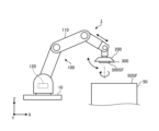
- FIG. 1 is a diagram showing an example of the external configuration of a droplet ejection system according to an embodiment.
- the droplet discharge system 1 includes a robot arm (an example of a robot part) 100, a control unit 120, a circulation device 200, and a droplet discharge head 300.
- the robot arm 100 is assembled to a base 10 that is placed on a horizontal floor surface indoors or outdoors, for example.
- Robot arm 100 has an arm section 110.
- the arm portion 110 is composed of a plurality of parts assembled so as to be bendable, straightenable, and rotatable.
- the arm section 110 can operate the droplet ejection head 300 (and the circulation device 200) mounted at the tip of the arm section 110 according to commands from the control unit 120.
- the arm section 110 can move the droplet ejection head 300 (and the circulation device 200) mounted at the tip of the arm section 110 in accordance with a command from the control unit 120.
- the arm section 110 can change the position of the droplet ejection head 300 (and the circulation device 200).
- the arm section 110 can rotate the droplet ejection head 300 (and the circulation device 200) around a predetermined rotation axis (for example, the Y axis or the Z axis) in accordance with a command from the control unit 120. Thereby, the arm section 110 can change the orientation, angle, and other postures of the droplet ejection head 300 (and the circulation device 200). Further, for example, the arm section 110 can perform various operations including swinging, tilting, and reversing of the droplet ejection head 300 (and the circulation device 200) in accordance with commands from the control unit 120.
- the arm section 110 illustrated in FIG. 1 is not particularly limited to the configuration illustrated in FIG. 1 as long as it has a degree of freedom that allows the position and posture of the droplet ejection head 300 to be changed.
- the control unit 120 is built into the robot arm 100 (arm part 110), for example. Note that the control unit 120 may be mounted on an external device independent from the robot arm 100 and connected to the robot arm 100 in a communicable manner.
- the control unit 120 controls the operation of the arm section 110 by outputting a command for controlling the operation of the arm section 110 to an actuator or the like that drives the arm section 110.
- the control unit 120 includes a control device 121 (see FIG. 6) such as a processor, and a storage device 122 (see FIG. 6) such as a memory.
- the storage device 122 includes, for example, a first control program 131 (see FIG.
- the control device 121 controls the operation of the robot arm 100 (arm section 110) based on programs, data, etc. stored in the storage device 122.
- the robot arm 100 moves the circulation device 200 and the droplet discharge head 300 mounted at the tip of the arm part 110 along a predetermined vertical axis (Z-axis) using the arm part 110, thereby moving the droplet discharge head 300.
- the position in the vertical direction (Z-axis direction) can be changed.
- the circulation device 200 and the droplet discharge head 300 for example, as shown in FIG. You can take a posture.
- the robot arm 100 can rotate, for example, the circulation device 200 and the droplet ejection head 300 assembled at the tip of the arm section 110 around a predetermined rotation axis by the arm section 110.
- the circulation device 200 and the droplet ejection head 300 can, for example, switch the longitudinal position and the lateral position, or reverse the vertical position.
- the circulation device 200 is installed at the tip of the arm section 110 of the robot arm 100.
- the circulation device 200 supplies the liquid to the droplet ejection head 300 while controlling the circulation pressure of the liquid circulating between the droplet ejection head 300 and the liquid.
- the droplet discharge head 300 is assembled to a circulation device 200 installed at the tip of the arm section 110 of the robot arm 100.
- the droplet ejection head 300 functions as a droplet ejection unit that ejects liquid to the object 50.
- the circulation pressure of the liquid supplied to the droplet ejection head 300 is affected by the operation of the droplet ejection head 300 by the robot arm 100.
- the circulation pressure (pressure) of the liquid inside the droplet discharge head 300 changes, for example, as shown in FIG. ,Change.
- FIG. 2 is a diagram illustrating changes in liquid pressure inside the droplet ejection head according to the embodiment. If the circulating pressure (pressure) of the liquid inside the droplet ejection head 300 changes, the liquid may not be ejected stably from the droplet ejection head 300.
- the present application proposes a droplet ejection system 1 that can flexibly respond to changes in the position of the droplet ejection head 300 and maintain appropriate circulation pressure of the liquid to be ejected.
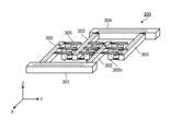
- FIG. 3 is a perspective view schematically showing the external configuration of the droplet ejection head according to the embodiment.
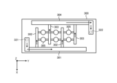
- FIG. 4 is a plan view of the droplet ejection head according to the embodiment.
- FIG. 5 is a diagram schematically showing a flow path inside the droplet ejection head according to the embodiment.
- the droplet ejection head 300 includes a housing including a box-shaped member 310 and a substantially flat plate-shaped member 320.
- the casing of the droplet ejection head 300 includes a first channel RT1 for supplying liquid from the circulation device 200 to the inside of the head, and a second channel RT1 for sending the liquid collected inside the head back to the circulation device 200.
- a flow path RT2 is installed.
- the member 320 of the droplet ejection head 300 has a supply port 321 through which liquid is supplied into the head through a first flow path RT1 , and a supply port 321 through which liquid is supplied into the head through a second flow path RT2 . It has a recovery port 322 through which liquid is recovered from inside.
- the droplet ejection head 300 includes a supply reservoir 301, a supply manifold 302, a recovery manifold 303, a recovery reservoir 304, and an element 305.
- the supply reservoir 301 has an elongated shape extending in the longitudinal direction (Y-axis direction) of the droplet ejection head 300 and is connected to the supply manifold 302 .
- Supply reservoir 301 has a flow path inside. As shown in FIG. 4 or 5, the liquid is supplied to the supply reservoir 301 through the first channel RT 1 and the supply port 321, and the liquid stored in the channel of the supply reservoir 301 is sent out to the supply manifold 302. .
- the supply manifold 302 has an elongated shape extending in the lateral direction (X-axis direction) of the droplet ejection head 300 to the front of the collection reservoir 304.
- the supply manifold 302 has a flow path therein that communicates with the flow path of the supply reservoir 301 and the element 305 . As shown in FIG. 4 or 5, liquid pumped from supply reservoir 301 to supply manifold 302 is pumped from supply manifold 302 to element 305.
- the recovery manifold 303 has an elongated shape that extends in the lateral direction (X-axis direction) of the droplet ejection head 300 to the front of the supply reservoir 301.
- the recovery manifold 303 has a channel therein that communicates with the channel included in the recovery reservoir 304 and the element 305 . As shown in FIG. 4 or 5, the liquid that is not discharged to the outside from the element 305 (discharge hole 305h) is sent to the recovery manifold 303.
- the collection reservoir 304 has an elongated shape extending in the longitudinal direction (Y-axis direction) of the droplet ejection head 300 and is connected to the collection manifold 303 .
- Recovery reservoir 304 has a flow path inside. As shown in FIG. 4 or 5, the liquid sent from the recovery manifold 303 to the recovery reservoir 304 and stored in the channel of the recovery reservoir 304 is passed through the recovery port 322 and the second channel RT 2 to the circulation device 200. sent back to.
- the element 305 has a discharge hole 305h.
- the element 305 sucks liquid from the supply manifold 302 using negative pressure generated in a pressure chamber (not shown), and directs the sucked liquid toward the object 50 from the discharge hole 305h using positive pressure generated in a pressure chamber (not shown). Dispense.
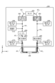
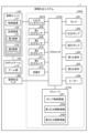
- FIG. 6 is a block diagram showing an example of the functional configuration of the droplet ejection system according to the embodiment.
- FIG. 7 is a diagram schematically showing the circulation mechanism of the circulation device in the droplet discharge system according to the embodiment.
- FIG. 6 shows an example of the functional configuration of the droplet discharge system 1 according to the embodiment, and as long as the configuration can realize various functions of the droplet discharge system 1 according to the embodiment, the configuration shown in FIG. There is no need to be particularly limited to the examples.
- FIG. 6 shows the components included in the droplet ejection system 1 according to the embodiment as functional blocks, and the description of other general components is omitted.
- each component of the droplet ejection system 1 shown in FIG. 6 is functionally conceptual, and is not limited to the example shown in FIG. 6, and may not necessarily be physically configured as shown. Not needed.
- the specific form of distribution/integration of each functional block is not limited to what is shown in the diagram, and all or part of it can be functionally or physically distributed in arbitrary units depending on various loads, usage conditions, etc. - Can be configured in an integrated manner.
- the droplet discharge system 1 includes a circulation device 200.
- the circulation device 200 includes a tank 201, a discharge pump 202, a suction pump 203, a first proportional valve 204, a second proportional valve 205, and a heater 206.
- the circulation device 200 also includes an input/output interface 207, a first pressure sensor 208, a second pressure sensor 209, a third pressure sensor 210, a fourth pressure sensor 211, and a flow meter 212.
- the circulation device 200 also includes a storage 214 and a processor 215. Note that the storage 214 and the processor 215 may be installed independently of the circulation device 200.
- the droplet ejection system 1 also includes a robot arm 100, a control unit 120, and a droplet ejection head 300.
- the circulation device 200 includes a first flow path RT1 and a second flow path RT2 .
- the first channel RT 1 is a channel that communicates between the tank 201 and the droplet discharge head 300 and allows the liquid stored in the tank 201 to flow into the droplet discharge head 300 .
- the second flow path RT 2 is a flow path that communicates between the tank 201 and the droplet ejection head 300 and allows the liquid that has flowed into the droplet ejection head 300 to flow back to the tank 201 .
- the liquid collected within the droplet ejection head 300 without being ejected to the outside from the droplet ejection head 300 is sent back to the tank 201 through the second channel RT 2 .
- the first flow path RT 1 and the second flow path RT 2 can be implemented, for example, by piping formed of a predetermined material that does not interact with liquid components.
- the processor 215 of the circulation device 200 having such various parts controls the circulation pressure of the liquid circulating clockwise between the tank 201 and the droplet ejection head 300, for example, as shown in FIG.
- the tank 201 stores liquid to be supplied to the droplet ejection head 300.
- the tank 201 functions as a storage section that stores liquid to be supplied to the droplet ejection head 300.
- the discharge pump 202 supplies the liquid stored in the tank 201 to the droplet discharge head 300 through the first channel RT1 .
- the discharge pump 202 generates positive pressure for discharging the liquid stored in the tank 201 to the droplet discharge head 300.
- the discharge pump 202 can, for example, deliver the liquid stored in the tank 201 to the droplet discharge head 300 at a preset constant supply pressure.
- the suction pump 203 supplies the liquid collected in the droplet ejection head 300 to the tank 201 through the second flow path RT2 .
- the suction pump 203 generates negative pressure to suck the liquid collected by the droplet discharge head 300 and send it back to the tank 201 .
- the suction pump 203 can send the liquid sucked from the droplet ejection head 300 to the tank 201, for example, at a preset constant recovery pressure.
- the discharge pump 202 and the suction pump 203 can be implemented by a rotary pump such as a gear pump or a positive displacement pump such as a diaphragm pump.
- the first proportional valve 204 is inserted into the first flow path RT1 between the tank 201 and the droplet discharge head 300, and is a first valve that proportionally controls the flow rate of the liquid supplied to the droplet discharge head 300. function as a department.
- the first proportional valve 204 can continuously change the cross-sectional area of the liquid flow path between 0 and 100%, and controls the flow rate of the liquid to a desired flow rate.
- the first proportional valve 204 can reduce the supply pressure when supplying the liquid to the droplet ejection head 300 by reducing the cross-sectional area of the liquid flow path.
- the first proportional valve 204 can increase the supply pressure when supplying the liquid to the droplet ejection head 300 by increasing the cross-sectional area of the liquid flow path.
- the second proportional valve 205 is inserted into the second flow path RT 2 between the tank 201 and the droplet discharge head 300, and proportionally controls the flow rate of the liquid supplied from the droplet discharge head 300 to the tank 201. It functions as a second valve part.
- the second proportional valve 205 like the first proportional valve 204, can continuously change the cross-sectional area of the liquid flow path between 0 and 100%, and controls the flow rate of the liquid to a desired flow rate.
- the second proportional valve 205 can reduce the recovery pressure when recovering the liquid from the droplet ejection head 300 by reducing the cross-sectional area of the liquid flow path.
- the second proportional valve 205 can increase the recovery pressure when recovering the liquid from the droplet ejection head 300 by increasing the cross-sectional area of the liquid flow path.
- the first proportional valve 204 and the second proportional valve 205 can be implemented by an electromagnetic proportional switching valve or a pneumatic proportional switching valve.
- the heater 206 is provided in the first flow path RT 1 or adjacent to the first flow path RT 1 and heats the liquid flowing through the first flow path RT 1 .
- the input/output interface 207 exchanges various information with the control unit 120 of the robot arm 100.
- the input/output interface 207 can receive, for example, a signal instructing to start ejecting the liquid and a signal instructing the end of ejecting the liquid from the control unit 120. Further, the input/output interface 207 can obtain information regarding the operation of the droplet ejection head 300 from the first control program 131 stored in the storage device 122 of the control unit 120 under the control of the processor 215. As the information regarding the operation of the droplet discharge head 300, for example, numerical values regarding the movement of the droplet discharge head 300 are acquired.
- Numerical values related to the movement of the droplet discharge head 300 include, for example, the position of the droplet discharge head 300 in the vertical direction, the acceleration in the vertical direction acting on the droplet discharge head 300, and the horizontal direction acting on the droplet discharge head 300. Examples include acceleration.
- the information regarding the operation of the droplet ejection head 300 may be, for example, numerical values regarding various operations including rocking, tilting, reversing, etc. of the droplet ejection head 300.
- the input/output interface 207 functions as an acquisition unit that acquires information regarding the operation of the droplet discharge head 300 from the first control program 131 that controls the operation of the robot arm 100 that operates the droplet discharge head 300.
- the first pressure sensor 208 measures the pressure of the liquid delivered from the tank 201 to the droplet ejection head 300 by the ejection pump 202.
- the first pressure sensor 208 measures the pressure downstream of the discharge pump 202 in the direction of liquid circulation in the circulation device 200 .
- First pressure sensor 208 sends measurement results to processor 215 .
- the second pressure sensor 209 measures the pressure of the liquid sucked from the droplet discharge head 300 by the suction pump 203 and fed to the tank 201.
- the second pressure sensor 209 measures the pressure upstream of the suction pump 203 in the direction of liquid circulation in the circulation device 200 .
- Second pressure sensor 209 sends measurement results to processor 215 .
- the third pressure sensor 210 functions as a first pressure measurement unit that measures the pressure of the liquid flowing between the first proportional valve 204 and the droplet ejection head 300 as a supply pressure through the first flow path RT1 . .
- the third pressure sensor 210 measures the pressure of the liquid just before it passes through the first proportional valve 204 and flows into the droplet ejection head 300 . That is, the third pressure sensor 210 measures the pressure downstream of the first proportional valve 204 in the circulation direction of the liquid in the circulation device 200 as the supply pressure.
- Third pressure sensor 210 sends measurement results to processor 215 .
- the fourth pressure sensor 211 functions as a second pressure measurement unit that measures the pressure of the liquid flowing between the second proportional valve 205 and the droplet discharge head 300 as a recovery pressure through the second flow path RT 2 . .
- the fourth pressure sensor 211 measures the pressure of the liquid immediately after it is sent out from the droplet ejection head 300 toward the tank 201 and before passing through the second proportional valve 205 . That is, the fourth pressure sensor 211 measures the pressure upstream of the second proportional valve 205 in the circulation direction of the liquid in the circulation device 200 as the recovery pressure. Fourth pressure sensor 211 sends measurement results to processor 215 .
- the flow meter 212 measures the flow rate of the liquid supplied to the droplet ejection head 300. Flow meter 212 sends measurement results to processor 215 .
- the storage 214 stores programs and data necessary for various processes of the droplet ejection system 1 (here, the circulation device 200).
- the storage 214 stores, for example, pump control information 241 and pressure adjustment information 242.
- the pump control information 241 is data for pump control that is set in advance.
- the data for pump control includes, for example, the target value of the pressure (positive pressure) applied to the liquid when the discharge pump 202 pumps out the liquid, and the pressure (negative pressure) applied to the liquid when the suction pump 203 sucks the liquid.
- the positive pressure of the ejection pump 202 is, for example, about 1.2 to 3 times higher than the pressure when liquid is supplied to the droplet ejection head 300.
- a value is set in advance as a target value.
- the negative pressure of the suction pump 203 is set in advance to a value approximately 1.2 to 3 times lower than the pressure at which liquid is supplied to the droplet ejection head 300 as a target value.
- the pressure adjustment information 242 includes adjustment values for each of the supply pressure and recovery pressure for suppressing changes in liquid pressure inside the droplet discharge head 300 for each numerical value related to the movement of the droplet discharge head 300. This is the associated data.
- FIG. 8 is a diagram showing an overview of pressure adjustment information according to the embodiment.
- the pressure adjustment information 242 includes an item of "numerical value related to head movement", an item of “adjustment value (supply pressure)", and an item of “adjustment value (recovery pressure)", and these items are are correlated with each other.
- the item “Numerical values related to head movement” includes the vertical position of the droplet ejection head 300, the vertical acceleration acting on the droplet ejection head 300, or the value related to the movement of the droplet ejection head 300.
- the horizontal acceleration acting on the head 300 is stored.
- a target value for adjusting the supply pressure hereinafter also referred to as “adjustment value” as appropriate
- a target value hereinafter also referred to as "adjustment value” as appropriate
- the pressure adjustment information 242 may be prepared depending on the type of numerical value related to the movement of the droplet ejection head 300. That is, the pressure adjustment information 242 is individually set for each of the vertical position of the droplet ejection head 300, the vertical acceleration acting on the droplet ejection head 300, and the horizontal acceleration acting on the droplet ejection head 300. May be provided.
- the processor 215 executes various processes in the droplet ejection system 1 (here, the circulation device 200) based on programs, data, etc. stored in the storage 214.
- the processor 215 realizes various functions for controlling each part of the droplet ejection system 1 (here, the circulation device 200) by reading and executing a computer program stored in the storage 214.
- the processor 215 Based on the measurement result of the first pressure sensor 208 and the measurement result of the third pressure sensor 210, the processor 215 adjusts the positive pressure applied to the liquid when the discharge pump 202 pumps out the liquid so as to keep it constant. For example, the processor 215 maintains the liquid pressure obtained from the measurement result of the first pressure sensor 208 at a pressure approximately 1.2 to 3 times greater than the liquid pressure obtained from the measurement result of the third pressure sensor 210. Then, adjust the positive pressure of the discharge pump 202.
- the processor 215 adjusts the negative pressure applied to the liquid when the suction pump 203 sucks the liquid so as to keep it constant. For example, the processor 215 maintains the liquid pressure obtained from the measurement result of the second pressure sensor 209 to be about 1.2 to 3 times lower than the liquid pressure obtained from the measurement result of the fourth pressure sensor 211. Then, adjust the negative pressure of the suction pump 203.
- the processor 215 controls the tank 201 and the droplet ejection head by adjusting the pressure difference between the positive pressure applied to the liquid by the ejection pump 202 and the negative pressure applied to the liquid by the suction pump 203 to be constant. 300.
- the processor 215 controls the first proportional valve 204 and the second proportional valve 205 based on the values obtained by the input/output interface 207, and adjusts the supply pressure and the recovery pressure. A method of controlling the first proportional valve 204 and the second proportional valve 205 will be described below with reference to FIGS. 9 to 11.
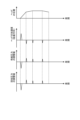
- FIG. 9 is a diagram for explaining a method of controlling the first proportional valve and the second proportional valve based on the position of the droplet ejection head according to the embodiment.
- the first row from the top of FIG. 9 schematically shows an example of the relationship between the position of the droplet ejection head 300 in the vertical direction and time.
- an example of the relationship between each adjustment value of the supply pressure and the recovery pressure and time is schematically shown.
- an example of the relationship between the circulation pressure of the liquid inside the droplet ejection head 300 and time is schematically shown.
- the attitude of the droplet ejection head 300 is such that the liquid ejection surface 300SF is directed vertically downward (see FIG. 1).
- the processor 215 controls the input/output interface 207 to obtain the position of the droplet ejection head 300 in the vertical direction. Specifically, the input/output interface 207 obtains the position of the droplet ejection head 300 in the vertical direction from the first control program 131 as a numerical value related to the movement of the droplet ejection head 300 .
- the processor 215 adjusts the supply pressure and the recovery pressure so that the circulating pressure (pressure) of the liquid inside the droplet ejection head 300, which changes depending on the acquired position of the droplet ejection head 300, remains constant.
- the circulation pressure (pressure) of the liquid is constant is a concept that includes not only the case where the pressure of the liquid is strictly constant but also the case where the pressure of the liquid approaches constant. That is, the processor 215 may adjust the supply pressure and the recovery pressure so that the circulation pressure (pressure) of the liquid inside the droplet ejection head 300 approaches a constant value.
- the processor 215 may adjust the supply pressure and withdrawal pressure so that the circulating pressure decreases if the pressure in the head increases, and adjusts the supply pressure and withdrawal pressure such that the circulating pressure increases if the pressure in the head decreases.
- the supply pressure and withdrawal pressure may be adjusted.
- the circulation pressure (pressure) of the liquid inside the droplet discharge head 300 decreases due to the influence of the water head pressure.
- the processor 215 refers to the pressure adjustment information 242 and identifies adjustment values for each of the supply pressure and recovery pressure that correspond to the acquired position of the droplet ejection head 300. The adjustment values of each of the supply pressure and recovery pressure increase as the position of the droplet ejection head 300 becomes higher.
- the processor 215 expands the flow passage cross-sectional area of the first proportional valve 204 in order to increase the supply pressure to the target pressure based on the specified adjustment value. , increases the flow rate of fluid passing through the first proportional valve 204.
- the processor 215 expands the cross-sectional area of the flow path of the second proportional valve 205 in order to increase the recovery pressure to the target pressure based on the specified adjustment value while referring to the measurement result of the fourth pressure sensor 211. , increases the flow rate of fluid passing through the second proportional valve 205.
- the processor 215 refers to the pressure adjustment information 242 and identifies adjustment values for each of the supply pressure and recovery pressure that correspond to the acquired position of the droplet ejection head 300. The adjustment values of each of the supply pressure and recovery pressure decrease as the position of the droplet ejection head 300 becomes lower.
- the processor 215 narrows the flow passage cross-sectional area of the first proportional valve 204 in order to reduce the supply pressure to the target pressure based on the specified adjustment value. , reducing the flow rate of fluid passing through the first proportional valve 204 .
- the processor 215 refers to the measurement result of the fourth pressure sensor 211 and narrows the flow path cross-sectional area of the second proportional valve 205 in order to reduce the recovery pressure to the target pressure based on the specified adjustment value. , reducing the flow rate of fluid passing through the second proportional valve 205.
- the processor 215 can increase or decrease the flow rate of the fluid passing through the first proportional valve 204 and the second proportional valve 205, depending on the position of the droplet ejection head 300 in the vertical direction. Thereby, the processor 215 can keep the circulating pressure (pressure) of the liquid inside the droplet ejection head 300 constant.
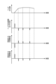
- FIG. 10 is a diagram for explaining a method of controlling the first proportional valve and the second proportional valve based on the vertical acceleration acting on the droplet ejection head according to the embodiment.
- the first row from the top of FIG. 10 schematically shows an example of the relationship between the position of the droplet ejection head 300 in the vertical direction and time.
- an example of the relationship between the vertical acceleration acting on the droplet ejection head 300 and time is schematically shown.
- the third and fourth rows from the top of FIG. 10 an example of the relationship between each adjustment value of the supply pressure and the recovery pressure and time is schematically shown.
- the attitude of the droplet ejection head 300 is such that the liquid ejection surface 300SF is directed vertically downward (see FIG. 1).
- the inside of the droplet discharge head 300 is affected by the water head pressure acting on the liquid circulating inside the head. It is expected that the circulating pressure (pressure) of the liquid at the If the circulating pressure (pressure) of the liquid inside the droplet ejection head 300 changes, the liquid may not be ejected stably from the droplet ejection head 300.
- the processor 215 controls the input/output interface 207 to obtain the vertical acceleration acting on the droplet ejection head 300.
- the input/output interface 207 obtains the vertical acceleration acting on the droplet ejection head 300 from the first control program 131 as a numerical value related to the movement of the droplet ejection head 300 .
- the processor 215 adjusts the supply pressure and the recovery pressure so that the circulation pressure (pressure) of the liquid inside the droplet ejection head 300, which changes according to the acquired vertical acceleration, remains constant.
- the circulation pressure (pressure) of the liquid inside the droplet ejection head 300 increases due to the influence of the water head pressure. Ru.
- the processor 215 refers to the pressure adjustment information 242 and identifies adjustment values for each of the supply pressure and recovery pressure that correspond to the acquired vertical acceleration. The adjustment values of each of the supply pressure and the recovery pressure decrease as the vertical upward acceleration of the droplet ejection head 300 increases.
- the processor 215 narrows the flow passage cross-sectional area of the first proportional valve 204 in order to reduce the supply pressure to the target pressure based on the specified adjustment value. , reducing the flow rate of fluid passing through the first proportional valve 204 .
- the processor 215 refers to the measurement result of the fourth pressure sensor 211 and narrows the flow path cross-sectional area of the second proportional valve 205 in order to reduce the recovery pressure to the target pressure based on the specified adjustment value. , reducing the flow rate of fluid passing through the second proportional valve 205.
- the circulation pressure (pressure) of the liquid inside the droplet discharge head 300 decreases due to the influence of the water head pressure. is expected.
- the processor 215 refers to the pressure adjustment information 242 and identifies adjustment values for each of the supply pressure and recovery pressure that correspond to the acquired position of the droplet ejection head 300. The adjustment values of each of the supply pressure and the recovery pressure increase as the vertical upward acceleration of the droplet ejection head 300 decreases.
- the processor 215 expands the flow passage cross-sectional area of the first proportional valve 204 in order to increase the supply pressure to the target pressure based on the specified adjustment value. , increases the flow rate of fluid passing through the first proportional valve 204.
- the processor 215 expands the cross-sectional area of the flow path of the second proportional valve 205 in order to increase the recovery pressure to the target pressure based on the specified adjustment value while referring to the measurement result of the fourth pressure sensor 211. , increases the flow rate of fluid passing through the second proportional valve 205.
- the processor 215 can increase or decrease the flow rate of the fluid passing through the first proportional valve 204 and the second proportional valve 205 in accordance with the vertical acceleration acting on the droplet ejection head 300. Thereby, the processor 215 can keep the circulating pressure (pressure) of the liquid inside the droplet ejection head 300 constant.
- FIG. 11 is a diagram for explaining a method of controlling the first proportional valve and the second proportional valve based on the horizontal acceleration acting on the droplet ejection head according to the embodiment.
- the first row from the top of FIG. 11 schematically shows an example of the relationship between the horizontal position of the droplet ejection head 300 and time.
- an example of the relationship between horizontal acceleration acting on the droplet ejection head 300 and time is schematically shown.
- an example of the relationship between each adjustment value of the supply pressure and the recovery pressure and time is schematically shown.
- the attitude of the droplet ejection head 300 is such that the liquid ejection surface 300SF is directed vertically downward (see FIG. 1).
- the horizontal acceleration acting on the droplet ejection head 300 is the acceleration of the liquid flowing inside the droplet ejection head 300 in a direction from the downstream side to the upstream side.
- the downstream side refers to the recovery side where liquid is recovered from the droplet ejection head 300 (that is, the recovery port 322 side)
- the upstream side refers to the recovery side where the liquid is supplied to the droplet ejection head 300.
- This is the supply side (that is, the supply port 321 side).
- the inside of the droplet discharge head 300 is affected by the head pressure acting on the liquid circulating inside the head. It is expected that the circulating pressure (pressure) of the liquid at the If the circulating pressure (pressure) of the liquid inside the droplet ejection head 300 changes, the liquid may not be ejected stably from the droplet ejection head 300.
- the processor 215 controls the input/output interface 207 to obtain the horizontal acceleration acting on the droplet ejection head 300.
- the input/output interface 207 obtains the horizontal acceleration acting on the droplet ejection head 300 from the first control program 131 as a numerical value related to the movement of the droplet ejection head 300 .
- the processor 215 adjusts the supply pressure and the recovery pressure so that the circulation pressure (pressure) of the liquid inside the droplet ejection head 300, which changes according to the acquired horizontal acceleration, remains constant.
- the processor 215 refers to the pressure adjustment information 242 to identify adjustment values for each of the supply pressure and the recovery pressure that correspond to the acquired horizontal acceleration.
- the adjustment value of the supply pressure decreases as the acceleration of the liquid flowing inside the droplet ejection head 300 in the direction from the downstream side to the upstream side increases.
- the adjustment value of the recovery pressure increases as the acceleration of the liquid flowing inside the droplet ejection head 300 in the direction from the downstream side to the upstream side increases.
- the processor 215 narrows the flow passage cross-sectional area of the first proportional valve 204 in order to reduce the supply pressure to the target pressure based on the specified adjustment value. , reducing the flow rate of fluid passing through the first proportional valve 204 .
- the processor 215 expands the cross-sectional area of the flow path of the second proportional valve 205 in order to increase the recovery pressure to the target pressure based on the specified adjustment value while referring to the measurement result of the fourth pressure sensor 211. , increases the flow rate of fluid passing through the second proportional valve 205.
- the processor 215 refers to the pressure adjustment information 242 to identify adjustment values for each of the supply pressure and the recovery pressure that correspond to the acquired horizontal acceleration.
- the adjustment value of the supply pressure increases as the acceleration of the liquid flowing inside the droplet ejection head 300 in the direction from the downstream side to the upstream side becomes smaller.
- the adjustment value of the recovery pressure decreases as the acceleration of the liquid flowing inside the droplet discharge head 300 in the direction from the downstream side to the upstream side decreases.
- the processor 215 expands the flow passage cross-sectional area of the first proportional valve 204 in order to increase the supply pressure to the target pressure based on the specified adjustment value. , increases the flow rate of fluid passing through the first proportional valve 204.
- the processor 215 refers to the measurement result of the fourth pressure sensor 211 and narrows the flow path cross-sectional area of the second proportional valve 205 in order to reduce the recovery pressure to the target pressure based on the specified adjustment value. , reducing the flow rate of fluid passing through the second proportional valve 205.
- the processor 215 can increase or decrease the flow rate of the fluid passing through the first proportional valve 204 and the second proportional valve 205 in accordance with the horizontal acceleration acting on the droplet ejection head 300. Thereby, the processor 215 can keep the circulating pressure (pressure) of the liquid inside the droplet ejection head 300 constant.
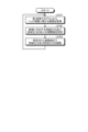
- FIG. 12 is a flowchart illustrating an example of the processing procedure of the droplet ejection system according to the embodiment.
- the processing shown in FIG. 12 is executed by the processor 215.
- the process shown in FIG. 12 is repeatedly executed while the droplet ejection system 1 is in operation.
- the processor 215 controls the input/output interface 207 to obtain numerical values regarding the movement of the droplet ejection head 300 from the first control program 131 (step S101). That is, the input/output interface 207 uses at least the following values: the vertical position of the droplet ejection head 300, the vertical acceleration acting on the droplet ejection head 300, and the horizontal acceleration acting on the droplet ejection head 300. Get one.
- the processor 215 refers to the pressure adjustment information 242 and identifies adjustment values for each of the supply pressure and recovery pressure that correspond to the acquired numerical values (step S102).
- the processor 215 adjusts the supply pressure and recovery pressure of the liquid circulating between the tank 201 and the droplet ejection head 300 to the specified adjustment value (step S103), and returns to the processing procedure of step S101.
- FIG. 13 is a block diagram showing an example of the functional configuration of a droplet ejection system according to another embodiment. Note that the circulation mechanism of the circulation device 200A in the droplet discharge system 1 according to another embodiment is similar to the circulation mechanism of the circulation device 200 in the droplet discharge system 1 according to the embodiment shown in FIG. omitted.
- a droplet discharge system 1 includes a circulation device 200A.
- the circulation device 200A includes an input/output interface 207A instead of the input/output interface 207 shown in FIG.
- the circulation device 200A includes a storage 214A and a processor 215A instead of the storage 214 and processor 215 shown in FIG.
- the input/output interface 207A exchanges various information with the control unit 120 of the robot arm 100. Like the input/output interface 207, the input/output interface 207A obtains numerical values regarding the movement of the droplet ejection head 300 from the first control program 131 stored in the storage device 122 of the control unit 120 under the control of the processor 215. can do. The input/output interface 207A can further acquire the printing rate of the droplet ejection head 300 from the second control program 132 stored in the storage device 122 of the control unit 120 under the control of the processor 215A.
- This "printing rate” refers to the ratio (S1/S2) of the cumulative area S1 of the liquid ejected onto the object 50 to the area S2 of the spray surface 50SF of the object 50 (S1/S2), and is calculated from the image data to be printed. can be done.
- the input/output interface 207A functions as an acquisition unit that acquires the printing rate of the droplet discharge head 300 from the second control program 132 that controls operations related to discharge of the droplet discharge head 300.
- the storage 214A stores programs and data necessary for various processes of the droplet ejection system 1 (here, the circulation device 200A).
- the storage 214A stores, for example, pump control information 241, first pressure adjustment information 242A, and second pressure adjustment information 243A.
- the pump control information 241 has the same data structure as the pump control information 241 shown in FIG.
- the first pressure adjustment information 242A has the same data structure as the pressure adjustment information 242 shown in FIG. 6.
- the second pressure adjustment information 243A includes adjustment values for each of the supply pressure and recovery pressure for suppressing changes in liquid pressure inside the droplet discharge head 300 for each print rate of the droplet discharge head 300. This is data that corresponds to FIG. 14 is a diagram showing an overview of second pressure adjustment information according to another embodiment.
- the second pressure adjustment information 243A includes an item of "printing rate”, an item of "adjustment value (supply pressure)", and an item of “adjustment value (recovery pressure)", and these items are are correlated with each other.
- the “printing rate” item stores the printing rate of the droplet ejection head 300.
- a target value for adjusting the supply pressure hereinafter also referred to as “adjustment value” as appropriate
- a target value hereinafter also referred to as “adjustment value” as appropriate
- the circulation pressure (pressure) of the liquid circulating inside the head changes, and the liquid may not be ejected stably from the droplet ejection head 300. . Therefore, through experiments, simulations, etc., the relationship between the respective adjustment values of the supply pressure and the recovery pressure is determined in advance so that the pressure of the liquid inside the head remains constant with respect to changes in the printing rate of the droplet ejection head 300.
- the supply pressure is obtained from the measurement result by the third pressure sensor 210.
- the recovery pressure is obtained from the measurement result by the fourth pressure sensor 211. Then, each adjustment value of the supply pressure and the recovery pressure is associated with each print rate of the droplet ejection head 300 and stored in the second pressure adjustment information 243A.
- the processor 215A controls the first proportional valve 204 and the second proportional valve 205 based on the numerical values obtained by the input/output interface 207A, and adjusts the supply pressure and the recovery pressure. In addition, in parallel with adjusting the supply pressure and recovery pressure based on these values, the processor 215A controls the first proportional valve 204 and the second proportional valve 205 based on the printing rate acquired by the input/output interface 207A. and adjust the supply pressure and recovery pressure. That is, the processor 215A adjusts the supply pressure and recovery pressure based on numerical values related to the operation of the droplet discharge head 300, and adjusts the supply pressure and recovery pressure based on the printing rate of the droplet discharge head 300 in parallel.
- a method of controlling the first proportional valve 204 and the second proportional valve 205 based on the printing rate of the droplet ejection head 300 will be described.
- the head pressure acts on the liquid circulating inside the head, so that the circulation pressure of the liquid inside the droplet discharge head 300 ( pressure) is expected to change. Furthermore, when the printing rate of the droplet ejection head 300 changes, it is expected that the circulation pressure (pressure) of the liquid inside the droplet ejection head 300 will also change. If the circulating pressure (pressure) of the liquid inside the droplet ejection head 300 changes, the liquid may not be ejected stably from the droplet ejection head 300.
- the processor 215A controls the input/output interface 207 to obtain numerical values regarding the movement of the droplet ejection head 300. Specifically, the input/output interface 207 acquires the position of the droplet ejection head 300 in the vertical direction, etc. from the first control program 131 as numerical values related to the movement of the droplet ejection head 300. Furthermore, the processor 215A controls the input/output interface 207A to obtain the printing rate of the droplet ejection head 300. Specifically, the input/output interface 207A obtains the printing rate of the droplet ejection head 300 from the second control program 132.
- the processor 215A adjusts the supply pressure and recovery pressure so that the circulation pressure (pressure) of the liquid inside the droplet ejection head 300, which changes depending on the acquired position of the droplet ejection head 300, remains constant.
- the method of controlling the first proportional valve 204 and the second proportional valve 205 based on the position of the droplet ejection head 300 is similar to the control method shown in FIGS. 9 to 11.
- the processor 215A adjusts the supply pressure and the recovery pressure so that the circulating pressure (pressure) of the liquid inside the droplet ejection head 300, which changes according to the obtained printing rate of the droplet ejection head 300, is constant. adjust.
- the processor 215A refers to the second pressure adjustment information 243A and specifies adjustment values for each of the supply pressure and the recovery pressure that correspond to the obtained printing rate of the droplet ejection head 300. The adjustment values of each of the supply pressure and recovery pressure increase as the printing rate of the droplet ejection head 300 increases.
- the processor 215A expands the flow passage cross-sectional area of the first proportional valve 204 in order to increase the supply pressure to the target pressure based on the specified adjustment value. , increases the flow rate of fluid passing through the first proportional valve 204.
- the processor 215A refers to the measurement result of the fourth pressure sensor 211 and expands the flow passage cross-sectional area of the second proportional valve 205 in order to increase the recovery pressure to the target pressure based on the specified adjustment value. , increases the flow rate of fluid passing through the second proportional valve 205.
- the processor 215A can increase or decrease the flow rate of the fluid passing through the first proportional valve 204 and the second proportional valve 205, depending on the printing rate of the droplet ejection head 300. Thereby, the processor 215A can keep the circulating pressure (pressure) of the liquid inside the droplet ejection head 300 constant.
- FIG. 15 is a flowchart illustrating an example of a processing procedure of a droplet ejection system according to another embodiment.
- the processing shown in FIG. 15 is executed by the processor 215A.
- the process shown in FIG. 15 is repeatedly executed while the droplet ejection system 1 is in operation.
- the processor 215A controls the input/output interface 207A to obtain numerical values regarding the movement of the droplet ejection head 300 from the first control program 131 (step S201). That is, the input/output interface 207A uses at least the following values: the vertical position of the droplet ejection head 300, the vertical acceleration acting on the droplet ejection head 300, and the horizontal acceleration acting on the droplet ejection head 300. Get one.
- the processor 215A controls the input/output interface 207A to obtain the printing rate of the droplet ejection head 300 from the second control program 132 (step S202).
- the processor 215A refers to the first pressure adjustment information 242A and specifies adjustment values for each of the supply pressure and recovery pressure that correspond to the acquired numerical values (step S203).
- the processor 215A adjusts the supply pressure and recovery pressure of the liquid circulating between the tank 201 and the droplet ejection head 300 to the specified adjustment value (step S204), and returns to the processing procedure of step S201.
- the processor 215A performs the processing steps S205 to S206 based on the printing rate of the droplet ejection head 300, overlapping the processing steps S203 to S204 based on numerical values regarding the operation of the droplet ejection head 300.
- the processor 215A refers to the second pressure adjustment information 243A and specifies adjustment values for each of the supply pressure and the recovery pressure that correspond to the obtained print rate of the droplet ejection head 300 (step S205).
- the processor 215A adjusts the supply pressure and recovery pressure of the liquid circulating between the tank 201 and the droplet ejection head 300 to the specified adjustment value (step S206), and returns to the processing procedure of step S201.
- the processor 215A determines that a water head pressure to the extent that it affects the circulation pressure of the liquid circulating in the droplet ejection head 300 is not generated. be able to. In such a case, the processor 215A may stop adjusting the supply pressure and recovery pressure based on numerical values related to the operation of the droplet ejection head 300 (processing procedures of steps S203 to S204). That is, when the water head pressure to the extent that it affects the circulation pressure of the liquid circulating in the droplet ejection head 300 is not generated, the processor 215A adjusts the supply pressure and recovery pressure based on the printing rate of the droplet ejection head 300. Only (the processing procedure of steps S205 and S206) is performed. Thereby, the circulation pressure (pressure) of the liquid inside the droplet ejection head 300 can be kept constant while suppressing an increase in processing load.
- the droplet ejection system 1 measures the flow rate of the liquid supplied to the droplet ejection head 300 with a flowmeter 212 connected to the first flow path RT1, as shown in FIGS. 6 and 7. The measured flow rate of the liquid and the ejection amount determined from the printing rate may be compared. Then, the droplet discharge system 1 adjusts the supply pressure and recovery pressure so as not to increase or decrease the circulation pressure when the discharge amount determined from the printing rate is larger than the flow rate of the liquid measured by the flowmeter 212. It may be adjusted.
- the processor 215A determines the ejection amount expected from the printing rate. At the same time, the flow rate of the liquid measured by the flow meter 212 is also obtained. Then, the processor 215A compares the ejection amount determined from the printing rate with the liquid flow rate measured by the flow meter 212. When the discharge amount determined from the printing rate is larger than the liquid flow rate measured by the flow meter 212, the processor 215A controls the first proportional valve 204 and the second proportional valve so as not to increase the circulating pressure or to decrease the circulating pressure. 205 may be controlled.
- the amount of ejection may decrease due to non-ejection of droplets due to air bubbles or foreign matter in many channels (ejection holes 305h).
- the circulation pressure may be adjusted to increase based on the information on the printing rate even though the actual discharge amount is small (see S205 and S206 in FIG. 15).
- the printing rate here is, for example, the ratio (S1/ S2) and can be calculated from the image data to be printed. If this happens, the pressure inside the droplet ejection head 300 will become inappropriately high, which may cause problems such as ink overflowing from the ejection holes 305h.
- the expected discharge amount is calculated from the printing rate, and the expected discharge amount value is compared with the measured value of the flowmeter 212. It is better not to increase the circulation pressure or to reduce it if the measured value of
- the measured value of the flow meter 212 is the sum of the ejected amount and the circulation flow rate, so it is normal for the ejected amount estimated from the printing rate to be smaller than the measured value of the flow meter 212.
- a state in which the ejection amount determined from the above-mentioned printing rate is greater than the flow rate measured by the flow meter 212 is not normal.
- the coating apparatus (for example, droplet discharge system 1) according to the embodiment includes a storage section (for example, tank 201), a robot section (for example, robot arm 100), and a first flow path (for example, , the first flow path RT 1 ), the second flow path (for example, the second flow path RT 2 ), the acquisition unit (for example, the input/output interfaces 207, 207A), and the control unit (for example, the processor 215, 215A).
- the storage section stores liquid to be supplied to the droplet ejection section (for example, the droplet ejection head 300).
- the robot section operates as a droplet discharge section.
- the first flow path is a flow path that communicates between the storage section and the droplet discharge section and allows the liquid stored in the storage section to flow into the droplet discharge section.
- the second flow path is a flow path that communicates between the storage section and the droplet discharge section and allows the liquid that has flowed into the droplet discharge section to flow back to the storage section.
- the acquisition unit acquires information regarding the operation of the droplet discharge unit from a program (for example, the first control program 131) that controls the operation of the robot unit.
- the control section controls the circulation pressure of the liquid circulating between the storage section and the droplet discharge section.
- the control unit controls the circulating pressure based on information regarding the operation.
- the coating apparatus includes a first valve part (for example, the first proportional valve 204), a second valve part (for example, the second proportional valve 205), and a first pressure measuring part (for example, the first proportional valve 205). 3 pressure sensor 210) and a second pressure measurement section (for example, a fourth pressure sensor 211).
- the first valve part may be inserted into the first flow path and control the flow rate of the liquid fed from the storage part to the droplet discharge part.
- the second valve section may be inserted into the second flow path and control the flow rate of the liquid delivered from the droplet discharge section to the storage section.
- the first pressure measuring section may measure the pressure of the liquid flowing between the first valve section and the droplet discharge section through the first flow path as the supply pressure.
- the second pressure measuring section may measure the pressure of the liquid flowing between the second valve section and the droplet discharge section through the second flow path as the recovery pressure.
- the acquisition unit may acquire numerical values related to the movement of the droplet discharge unit from a program that controls the operation of the robot unit.
- the control unit may control the first valve unit and the second valve unit to adjust the supply pressure and the recovery pressure based on the numerical value acquired by the acquisition unit.
- the acquisition unit may acquire the position of the droplet ejection unit in the vertical direction as a numerical value.
- the control unit may adjust the supply pressure and the recovery pressure so that the pressure of the liquid inside the droplet discharge unit, which changes depending on the position, is constant. For example, the adjustment values for each of the supply pressure and the withdrawal pressure may increase as the position becomes higher.
- the liquid supply and withdrawal pressures can be adjusted to compensate.
- the acquisition unit may acquire the vertical acceleration acting on the droplet ejection unit as a numerical value.
- the control unit may adjust the supply pressure and the recovery pressure so that the pressure of the liquid inside the droplet discharge unit, which changes depending on the acceleration in the vertical direction, is constant. For example, the adjustment values for each of the supply pressure and the recovery pressure may decrease as the vertical upward acceleration increases.
- the acquisition unit may acquire the horizontal acceleration acting on the droplet ejection unit as a numerical value.
- the control unit may adjust the supply pressure and the recovery pressure so that the pressure of the liquid inside the droplet discharge unit, which changes depending on the acceleration in the horizontal direction, remains constant.
- the adjustment value of the supply pressure may decrease as the acceleration of the liquid flowing inside the droplet discharge section in the direction from the downstream side to the upstream side increases.
- the adjustment value of the recovery pressure may increase as the acceleration in the direction from the downstream side to the upstream side of the liquid flowing inside the droplet discharge section increases.
- the coating apparatus According to the coating apparatus according to the embodiment, even if the liquid circulating in the droplet discharge section is affected by the head pressure due to a change in the horizontal acceleration acting on the droplet discharge section, the water head pressure is reduced. Liquid supply and withdrawal pressures can be adjusted to counteract the effects.
- the coating apparatus may further include a storage unit (for example, storage 214).
- the storage unit stores pressure adjustment information (for example, pressure adjustment) that associates each adjustment value of supply pressure and recovery pressure for suppressing changes in liquid pressure inside the droplet discharge unit for each numerical value. information 242) may be stored.
- the control unit may refer to the pressure adjustment information and adjust the supply pressure and recovery pressure to adjustment values corresponding to the numerical values acquired by the acquisition unit.
- the acquisition unit may further acquire the printing rate of the droplet discharge unit from a program (for example, the second control program 132) that controls operations related to discharge of the droplet discharge unit.
- the control unit (for example, processor 215A) adjusts the supply pressure and recovery pressure based on the numerical value acquired by the acquisition unit, and also adjusts the supply pressure and recovery pressure based on the printing rate acquired by the acquisition unit. You may.
- the circulation pressure of the liquid supplied to the droplet discharge section is affected by the movement of the liquid discharge section by the robot section or the printing rate of the droplet discharge section. , circulation pressure can be maintained appropriately.
- the control unit may adjust the supply pressure and the recovery pressure so that the pressure of the liquid inside the droplet discharge unit, which changes depending on the printing rate of the droplet discharge unit, remains constant.
- the adjustment values for each of the supply pressure and the recovery pressure may increase as the printing rate of the droplet ejection unit increases.
- the coating apparatus may further include a storage unit (for example, storage 214A).
- the storage unit stores first pressure adjustment information (for example, The first pressure adjustment information 242A) and the adjustment values for each of the supply pressure and recovery pressure to suppress changes in liquid pressure inside the droplet discharge unit are determined for each print rate of the droplet discharge unit.
- the associated second pressure adjustment information (for example, second pressure adjustment information 243A) may also be stored.
- the control unit (for example, the processor 215A) may refer to the first pressure adjustment information and adjust the supply pressure and recovery pressure to the adjustment value corresponding to the numerical value acquired by the acquisition unit.
- the control unit may refer to the second pressure adjustment information and adjust the supply pressure and the recovery pressure to the adjustment value corresponding to the printing rate acquired by the acquisition unit.
- the supply pressure and collection pressure can be adjusted based on various numerical values regarding the movement of the droplet discharge unit, and the supply pressure and collection pressure can be adjusted based on the printing rate of the droplet discharge unit. can be done in parallel.
- control unit may stop adjusting the supply pressure and the recovery pressure based on the numerical value.
- Droplet discharge system 10 Base 50 Target object 50SF Spray surface 100 Robot arm 110 Arm section 120 Control unit 121 Control device 122 Storage device 131 First control program 132 Second control program 200, 200A Circulation device 201 Tank 202 Discharge pump 203 Suction pump 204 First proportional valve 205 Second proportional valve 206 Heater 207, 207A Input/output interface 208 First pressure sensor 209 Second pressure sensor 210 Third pressure sensor 211 Fourth pressure sensor 212 Flow meter 214, 214A Storage 215, 215A Processor 241 Pump control information 242 Pressure adjustment information 242A First pressure adjustment information 243A Second pressure adjustment information 300 Droplet discharge head 300SF Discharge surface 301 Supply reservoir 302 Supply manifold 303 Recovery manifold 304 Recovery reservoir 305 Element 305h Discharge holes 310, 320 Member 321 Supply port 322 Recovery port RT1 First channel RT2 Second channel
Landscapes
- Chemical & Material Sciences (AREA)
- Analytical Chemistry (AREA)
- Physics & Mathematics (AREA)
- Fluid Mechanics (AREA)
- Engineering & Computer Science (AREA)
- Robotics (AREA)
- Coating Apparatus (AREA)
- Ink Jet (AREA)
- Application Of Or Painting With Fluid Materials (AREA)
- Spray Control Apparatus (AREA)
Priority Applications (4)
| Application Number | Priority Date | Filing Date | Title |
|---|---|---|---|
| EP23780177.4A EP4501467A4 (en) | 2022-03-28 | 2023-03-24 | COATING DEVICE AND COATING METHOD |
| JP2024512357A JP7758858B2 (ja) | 2022-03-28 | 2023-03-24 | 塗装装置及び塗装方法 |
| CN202380030972.2A CN118973720A (zh) | 2022-03-28 | 2023-03-24 | 涂装装置以及涂装方法 |
| JP2025171158A JP2025185110A (ja) | 2022-03-28 | 2025-10-09 | 塗装装置及び塗装方法 |
Applications Claiming Priority (2)
| Application Number | Priority Date | Filing Date | Title |
|---|---|---|---|
| JP2022-051340 | 2022-03-28 | ||
| JP2022051340 | 2022-03-28 |
Publications (1)
| Publication Number | Publication Date |
|---|---|
| WO2023190167A1 true WO2023190167A1 (ja) | 2023-10-05 |
Family
ID=88201448
Family Applications (1)
| Application Number | Title | Priority Date | Filing Date |
|---|---|---|---|
| PCT/JP2023/011840 Ceased WO2023190167A1 (ja) | 2022-03-28 | 2023-03-24 | 塗装装置及び塗装方法 |
Country Status (4)
| Country | Link |
|---|---|
| EP (1) | EP4501467A4 (https=) |
| JP (2) | JP7758858B2 (https=) |
| CN (1) | CN118973720A (https=) |
| WO (1) | WO2023190167A1 (https=) |
Citations (9)
| Publication number | Priority date | Publication date | Assignee | Title |
|---|---|---|---|---|
| JP2007326037A (ja) * | 2006-06-07 | 2007-12-20 | Asahi Sunac Corp | 塗料供給装置及び塗料供給方法 |
| JP2010012432A (ja) | 2008-07-04 | 2010-01-21 | Hitachi High-Technologies Corp | インクジェット式塗布装置 |
| JP2012152710A (ja) * | 2011-01-27 | 2012-08-16 | Iec Co Ltd | 塗料供給システム |
| JP2015167934A (ja) * | 2014-03-10 | 2015-09-28 | 芝浦メカトロニクス株式会社 | 塗布装置 |
| JP2018149482A (ja) * | 2017-03-13 | 2018-09-27 | 住友重機械工業株式会社 | インク吐出装置及びインク劣化度検知方法 |
| JP2020124912A (ja) * | 2019-02-06 | 2020-08-20 | ゼロックス コーポレイションXerox Corporation | 関節運動アームによって移動された印刷ヘッド内のインク浸出及び空気摂取を減衰させるためのシステム及び方法 |
| WO2021040034A1 (ja) * | 2019-08-30 | 2021-03-04 | 京セラ株式会社 | 循環装置 |
| JP2021183417A (ja) * | 2020-05-21 | 2021-12-02 | ザ・ボーイング・カンパニーThe Boeing Company | メニスカス圧が動的に制御されるインクジェット印刷システム |
| WO2022049718A1 (ja) * | 2020-09-04 | 2022-03-10 | アーベーベー・シュバイツ・アーゲー | 塗装ロボット |
Family Cites Families (2)
| Publication number | Priority date | Publication date | Assignee | Title |
|---|---|---|---|---|
| US11850868B2 (en) * | 2019-08-30 | 2023-12-26 | Kyocera Corporation | Circulation device |
| CN114555239B (zh) * | 2020-06-18 | 2023-08-18 | Abb瑞士股份有限公司 | 涂装机器人及使用涂装机器人的涂装方法 |
-
2023
- 2023-03-24 WO PCT/JP2023/011840 patent/WO2023190167A1/ja not_active Ceased
- 2023-03-24 JP JP2024512357A patent/JP7758858B2/ja active Active
- 2023-03-24 EP EP23780177.4A patent/EP4501467A4/en active Pending
- 2023-03-24 CN CN202380030972.2A patent/CN118973720A/zh active Pending
-
2025
- 2025-10-09 JP JP2025171158A patent/JP2025185110A/ja active Pending
Patent Citations (9)
| Publication number | Priority date | Publication date | Assignee | Title |
|---|---|---|---|---|
| JP2007326037A (ja) * | 2006-06-07 | 2007-12-20 | Asahi Sunac Corp | 塗料供給装置及び塗料供給方法 |
| JP2010012432A (ja) | 2008-07-04 | 2010-01-21 | Hitachi High-Technologies Corp | インクジェット式塗布装置 |
| JP2012152710A (ja) * | 2011-01-27 | 2012-08-16 | Iec Co Ltd | 塗料供給システム |
| JP2015167934A (ja) * | 2014-03-10 | 2015-09-28 | 芝浦メカトロニクス株式会社 | 塗布装置 |
| JP2018149482A (ja) * | 2017-03-13 | 2018-09-27 | 住友重機械工業株式会社 | インク吐出装置及びインク劣化度検知方法 |
| JP2020124912A (ja) * | 2019-02-06 | 2020-08-20 | ゼロックス コーポレイションXerox Corporation | 関節運動アームによって移動された印刷ヘッド内のインク浸出及び空気摂取を減衰させるためのシステム及び方法 |
| WO2021040034A1 (ja) * | 2019-08-30 | 2021-03-04 | 京セラ株式会社 | 循環装置 |
| JP2021183417A (ja) * | 2020-05-21 | 2021-12-02 | ザ・ボーイング・カンパニーThe Boeing Company | メニスカス圧が動的に制御されるインクジェット印刷システム |
| WO2022049718A1 (ja) * | 2020-09-04 | 2022-03-10 | アーベーベー・シュバイツ・アーゲー | 塗装ロボット |
Non-Patent Citations (1)
| Title |
|---|
| See also references of EP4501467A4 |
Also Published As
| Publication number | Publication date |
|---|---|
| JPWO2023190167A1 (https=) | 2023-10-05 |
| EP4501467A4 (en) | 2026-03-11 |
| JP7758858B2 (ja) | 2025-10-22 |
| EP4501467A1 (en) | 2025-02-05 |
| JP2025185110A (ja) | 2025-12-18 |
| CN118973720A (zh) | 2024-11-15 |
Similar Documents
| Publication | Publication Date | Title |
|---|---|---|
| JP7256274B2 (ja) | 循環装置 | |
| US10259234B2 (en) | Inkjet printing system having dynamically controlled ink reservoir | |
| JP7787132B2 (ja) | 循環装置 | |
| KR20120069774A (ko) | 액체 순환 시스템 | |
| US11413877B2 (en) | Inkjet printing system having dynamically controlled meniscus pressure | |
| CN109789703B (zh) | 印刷总成 | |
| US9827772B2 (en) | Inkjet device and inkjet method in which an ink is discharged while being circulated | |
| JP2022523375A (ja) | 印刷コントローラおよび印刷の方法 | |
| WO2023190167A1 (ja) | 塗装装置及び塗装方法 | |
| JP2025126357A (ja) | 液滴吐出装置及びメンテナンス方法 | |
| JP7612788B2 (ja) | ガス制御システム、製造装置、及び方法 | |
| US11724513B2 (en) | Liquid circulation mechanism, liquid circulation device, and liquid discharging apparatus | |
| JP2025058874A (ja) | 流体流れ回路内の流体圧の動的制御 | |
| EP3463904B1 (en) | Buffer reservoirs | |
| WO2021183108A1 (en) | Valve control based on print data |
Legal Events
| Date | Code | Title | Description |
|---|---|---|---|
| 121 | Ep: the epo has been informed by wipo that ep was designated in this application |
Ref document number: 23780177 Country of ref document: EP Kind code of ref document: A1 |
|
| ENP | Entry into the national phase |
Ref document number: 2024512357 Country of ref document: JP Kind code of ref document: A |
|
| WWE | Wipo information: entry into national phase |
Ref document number: 202380030972.2 Country of ref document: CN |
|
| WWE | Wipo information: entry into national phase |
Ref document number: 2023780177 Country of ref document: EP |
|
| NENP | Non-entry into the national phase |
Ref country code: DE |
|
| ENP | Entry into the national phase |
Ref document number: 2023780177 Country of ref document: EP Effective date: 20241028 |