WO2023188846A1 - 吸着フィルター、吸着ロータ、及び吸着処理装置 - Google Patents
吸着フィルター、吸着ロータ、及び吸着処理装置 Download PDFInfo
- Publication number
- WO2023188846A1 WO2023188846A1 PCT/JP2023/004146 JP2023004146W WO2023188846A1 WO 2023188846 A1 WO2023188846 A1 WO 2023188846A1 JP 2023004146 W JP2023004146 W JP 2023004146W WO 2023188846 A1 WO2023188846 A1 WO 2023188846A1
- Authority
- WO
- WIPO (PCT)
- Prior art keywords
- adsorption
- gas
- nonwoven fabric
- rotor
- adsorbent
- Prior art date
- Legal status (The legal status is an assumption and is not a legal conclusion. Google has not performed a legal analysis and makes no representation as to the accuracy of the status listed.)
- Ceased
Links
Images


Classifications
-
- B—PERFORMING OPERATIONS; TRANSPORTING
- B01—PHYSICAL OR CHEMICAL PROCESSES OR APPARATUS IN GENERAL
- B01D—SEPARATION
- B01D53/00—Separation of gases or vapours; Recovering vapours of volatile solvents from gases; Chemical or biological purification of waste gases, e.g. engine exhaust gases, smoke, fumes, flue gases, aerosols
- B01D53/26—Drying gases or vapours
- B01D53/261—Drying gases or vapours by adsorption
-
- B—PERFORMING OPERATIONS; TRANSPORTING
- B01—PHYSICAL OR CHEMICAL PROCESSES OR APPARATUS IN GENERAL
- B01D—SEPARATION
- B01D39/00—Filtering material for liquid or gaseous fluids
- B01D39/14—Other self-supporting filtering material ; Other filtering material
- B01D39/16—Other self-supporting filtering material ; Other filtering material of organic material, e.g. synthetic fibres
- B01D39/1607—Other self-supporting filtering material ; Other filtering material of organic material, e.g. synthetic fibres the material being fibrous
- B01D39/1623—Other self-supporting filtering material ; Other filtering material of organic material, e.g. synthetic fibres the material being fibrous of synthetic origin
-
- B—PERFORMING OPERATIONS; TRANSPORTING
- B01—PHYSICAL OR CHEMICAL PROCESSES OR APPARATUS IN GENERAL
- B01D—SEPARATION
- B01D53/00—Separation of gases or vapours; Recovering vapours of volatile solvents from gases; Chemical or biological purification of waste gases, e.g. engine exhaust gases, smoke, fumes, flue gases, aerosols
- B01D53/02—Separation of gases or vapours; Recovering vapours of volatile solvents from gases; Chemical or biological purification of waste gases, e.g. engine exhaust gases, smoke, fumes, flue gases, aerosols by adsorption, e.g. preparative gas chromatography
- B01D53/06—Separation of gases or vapours; Recovering vapours of volatile solvents from gases; Chemical or biological purification of waste gases, e.g. engine exhaust gases, smoke, fumes, flue gases, aerosols by adsorption, e.g. preparative gas chromatography with moving adsorbents, e.g. rotating beds
-
- B—PERFORMING OPERATIONS; TRANSPORTING
- B01—PHYSICAL OR CHEMICAL PROCESSES OR APPARATUS IN GENERAL
- B01D—SEPARATION
- B01D53/00—Separation of gases or vapours; Recovering vapours of volatile solvents from gases; Chemical or biological purification of waste gases, e.g. engine exhaust gases, smoke, fumes, flue gases, aerosols
- B01D53/26—Drying gases or vapours
- B01D53/28—Selection of materials for use as drying agents
-
- F—MECHANICAL ENGINEERING; LIGHTING; HEATING; WEAPONS; BLASTING
- F24—HEATING; RANGES; VENTILATING
- F24F—AIR-CONDITIONING; AIR-HUMIDIFICATION; VENTILATION; USE OF AIR CURRENTS FOR SCREENING
- F24F1/00—Room units for air-conditioning, e.g. separate or self-contained units or units receiving primary air from a central station
- F24F1/0007—Indoor units, e.g. fan coil units
- F24F1/0083—Indoor units, e.g. fan coil units with dehumidification means
-
- F—MECHANICAL ENGINEERING; LIGHTING; HEATING; WEAPONS; BLASTING
- F24—HEATING; RANGES; VENTILATING
- F24F—AIR-CONDITIONING; AIR-HUMIDIFICATION; VENTILATION; USE OF AIR CURRENTS FOR SCREENING
- F24F3/00—Air-conditioning systems in which conditioned primary air is supplied from one or more central stations to distributing units in the rooms or spaces where it may receive secondary treatment; Apparatus specially designed for such systems
- F24F3/12—Air-conditioning systems in which conditioned primary air is supplied from one or more central stations to distributing units in the rooms or spaces where it may receive secondary treatment; Apparatus specially designed for such systems characterised by the treatment of the air otherwise than by heating and cooling
- F24F3/14—Air-conditioning systems in which conditioned primary air is supplied from one or more central stations to distributing units in the rooms or spaces where it may receive secondary treatment; Apparatus specially designed for such systems characterised by the treatment of the air otherwise than by heating and cooling by humidification; by dehumidification
- F24F3/1411—Air-conditioning systems in which conditioned primary air is supplied from one or more central stations to distributing units in the rooms or spaces where it may receive secondary treatment; Apparatus specially designed for such systems characterised by the treatment of the air otherwise than by heating and cooling by humidification; by dehumidification by absorbing or adsorbing water, e.g. using an hygroscopic desiccant
- F24F3/1423—Air-conditioning systems in which conditioned primary air is supplied from one or more central stations to distributing units in the rooms or spaces where it may receive secondary treatment; Apparatus specially designed for such systems characterised by the treatment of the air otherwise than by heating and cooling by humidification; by dehumidification by absorbing or adsorbing water, e.g. using an hygroscopic desiccant with a moving bed of solid desiccants, e.g. a rotary wheel supporting solid desiccants
-
- B—PERFORMING OPERATIONS; TRANSPORTING
- B01—PHYSICAL OR CHEMICAL PROCESSES OR APPARATUS IN GENERAL
- B01D—SEPARATION
- B01D2239/00—Aspects relating to filtering material for liquid or gaseous fluids
- B01D2239/04—Additives and treatments of the filtering material
- B01D2239/0407—Additives and treatments of the filtering material comprising particulate additives, e.g. adsorbents
-
- B—PERFORMING OPERATIONS; TRANSPORTING
- B01—PHYSICAL OR CHEMICAL PROCESSES OR APPARATUS IN GENERAL
- B01D—SEPARATION
- B01D2253/00—Adsorbents used in seperation treatment of gases and vapours
- B01D2253/20—Organic adsorbents
- B01D2253/204—Metal organic frameworks (MOF's)
-
- F—MECHANICAL ENGINEERING; LIGHTING; HEATING; WEAPONS; BLASTING
- F24—HEATING; RANGES; VENTILATING
- F24F—AIR-CONDITIONING; AIR-HUMIDIFICATION; VENTILATION; USE OF AIR CURRENTS FOR SCREENING
- F24F2203/00—Devices or apparatus used for air treatment
- F24F2203/10—Rotary wheel
- F24F2203/1032—Desiccant wheel
Definitions
- the present disclosure relates to an adsorption filter, an adsorption rotor, and an adsorption processing device.
- a dehumidifying device 110 that includes a cylindrical suction rotor 111 that is rotatable around a rotation axis L (see, for example, Patent Document 1).
- the adsorption rotor 111 generally includes an adsorption element 112 having a honeycomb structure.
- the adsorption element 112 is formed of, for example, an adsorption sheet in which an adsorbent such as silica gel is supported on a nonwoven fabric base material.
- the suction sheet includes a flat liner sheet 113A and a corrugated corrugated sheet 113B with repeated irregularities along the longitudinal direction.
- the adsorption element 112 has a honeycomb structure in which a large number of voids 114 extending in the length direction perpendicular to the radial direction are closely lined up by stacking liner sheets 113A and corrugated sheets 113B alternately in the radial direction.
- the suction rotor 111 is divided into a suction zone and a desorption zone along the circumferential direction around the rotating shaft.
- a gas to be treated such as outside air
- the gas to be treated passes through the adsorption elements 112 by flowing through the gaps 114 of each of the adsorption elements 112 located in the adsorption zone, and at this time, moisture in the gas to be treated is adsorbed by the adsorbent. Thereby, the gas to be processed is dehumidified.
- a regeneration gas such as high temperature air is supplied to the adsorption rotor 111.
- the regeneration gas flows through the respective voids 114 of the adsorption elements 112 located in the desorption zone and passes through the adsorption elements 112, desorbing moisture from the adsorption material. This regenerates the adsorbent.
- the adsorption element 112 has a honeycomb structure. Since the gas to be treated and the regeneration gas flow through the respective gaps 114 of the adsorption element 112, they flow in parallel to the surface of the adsorption element 112 during dehumidification or regeneration. Therefore, pressure loss when the gas to be treated and the regeneration gas pass through the adsorption element 112 can be reduced.
- Honeycomb-structured adsorption elements have low pressure loss, but when the gas to be treated flows in parallel to the surface of the adsorption element, the adsorbent supported on the surface of the adsorption element easily mixes with the gas to be treated. It comes into contact with water and absorbs moisture. On the other hand, the adsorbent supported inside the adsorption element is difficult to come into contact with the gas to be treated and is difficult to adsorb moisture. Therefore, the adsorption element having a honeycomb structure cannot effectively utilize the adsorbent and has poor dehumidification performance. Furthermore, since the adsorption element having a honeycomb structure has a low contact efficiency between the regenerating gas and the adsorbent like the gas to be treated, the energy efficiency during regeneration is low and the environmental load is large.
- silica gel when used as an adsorbent, a regeneration gas of 140° C. or higher is required during regeneration, which also imposes a large environmental burden.
- the present disclosure has a high contact efficiency between the gas to be treated and the regenerated gas and the adsorbent, which improves the dehumidification performance and the energy efficiency during regeneration, and the regeneration compared to using silica gel as the adsorbent. It is an object of the present invention to provide an adsorption rotor that can sometimes save energy, an adsorption filter that constitutes the adsorption rotor, and an adsorption processing device using the adsorption rotor.
- the present disclosure relates to an adsorption filter that adsorbs moisture contained in a gas to be processed.
- the adsorption filter of the present disclosure includes a casing having a pair of gas flow ports facing each other, and an adsorption element in which an adsorption material is supported on a nonwoven fabric base material, the adsorption element housed in the casing.
- the adsorption element has a first bent portion that protrudes convexly in one direction, and a second bent portion that protrudes convexly in the other direction opposite to the one direction.
- the adsorbent is formed into a pleat shape facing the other gas flow port, and the adsorbent is a porous metal complex consisting of a metal and an organic ligand, and the adsorbent is a porous metal complex composed of a metal and an organic ligand, and It is characterized by being supported on the surface.
- a preferred embodiment of the adsorption filter of the present disclosure is characterized in that the adsorbent is supported on the surface of the fibers constituting the nonwoven fabric base material by adhesion or synthesis.
- a preferred embodiment of the adsorption filter of the present disclosure is characterized in that the pressure loss is 2 kPa or less.
- a preferred embodiment of the adsorption filter of the present disclosure is characterized in that the adsorption element has a length of 100 mm or more in a direction from the gas flow port to the gas flow port.
- the nonwoven fabric base material is at least one member selected from the group consisting of a phenolic resin fiber nonwoven fabric, a polyphenylene ether fiber nonwoven fabric, a flame resistant polyphenylene ether fiber nonwoven fabric, a flame resistant polyacrylonitrile fiber nonwoven fabric, and a PET nonwoven fabric. It is characterized by being formed using.
- the adsorption element has 15% of the adsorption material. It is characterized by containing at least 80% by mass.
- the present disclosure also relates to an adsorption treatment device that adsorbs moisture contained in a gas to be treated.
- the adsorption processing device of the present disclosure is characterized in that it includes a plurality of adsorption filters of the present disclosure, and the adsorption filters are arranged along the circumferential direction around the rotation axis of the adsorption rotor.
- the present disclosure also relates to an adsorption rotor that adsorbs moisture contained in a gas to be processed.
- the suction rotor of the present disclosure includes the suction rotor of the present disclosure, a drive mechanism that rotates the suction rotor, and an inflow into the suction filter that is moved to a suction zone that is a partial region in the circumferential direction due to rotation of the suction rotor.
- a flow path forming a flow path for causing flow to flow into and out of the adsorption filter that has been moved to a desorption zone that is a partial area in the circumferential direction and is separated from the adsorption zone by rotation of the adsorption rotor.
- a forming member is forming member.
- the present disclosure includes an adsorption filter, an adsorption rotor, and an adsorption processing device according to the embodiments described below.
- Item 1 An adsorption filter that adsorbs moisture contained in gas to be treated, a casing having a pair of gas flow ports facing each other; An adsorption element in which an adsorption material is supported on a nonwoven fabric base material, the adsorption element housed in the casing; Equipped with The adsorption element has a first bent portion that protrudes convexly in one direction, and a second bent portion that protrudes convexly in the other direction opposite to the one direction, which faces one of the gas flow ports.
- the adsorbent is a porous metal complex consisting of metal ions and organic ligands, and is supported on the surface of fibers constituting the nonwoven fabric base material.
- Item 2. The adsorption filter according to item 1, wherein the adsorbent is supported on the surface of fibers constituting the nonwoven fabric base material by adhesion or synthesis.
- Item 3. Item 2. The adsorption filter according to item 1 or item 2, wherein the pressure loss is 2 kPa or less.
- Item 5 Item 1, wherein the nonwoven fabric base material is formed using at least one selected from the group consisting of phenolic resin fiber nonwoven fabric, polyphenylene ether fiber nonwoven fabric, flame resistant polyphenylene ether fiber nonwoven fabric, flame resistant polyacrylonitrile fiber nonwoven fabric, and PET nonwoven fabric.
- An adsorption rotor comprising a plurality of adsorption filters according to any one of Items 1 to 6, A suction rotor, wherein the suction filter is arranged along a circumferential direction around a rotation axis of the suction rotor. Section 8.
- the suction rotor according to item 7, a drive mechanism that rotates the suction rotor;
- the rotation of the suction rotor causes the suction filter to flow into and out of the adsorption zone that is a partial region in the circumferential direction, and the rotation of the suction rotor causes the suction filter to flow into and out of the suction filter that is a partial region in the circumferential direction and the suction zone.
- a flow path forming member that forms a flow path for flowing in and out of the adsorption filter that has been moved to a regeneration zone separated from;
- the adsorption element formed in a pleated shape has its first bent portion facing one gas flow port of the casing and its second bent portion facing toward one gas flow port of the casing. is housed in the casing with the part facing the other gas flow port of the casing. Therefore, the gas to be treated and the regeneration gas pass through the adsorption element, crossing a portion of the adsorption element. Therefore, the gas to be treated and the regeneration gas come into good contact not only with the adsorbent supported on the surface side of the adsorption element but also with the adsorbent supported inside the adsorption element.
- the contact efficiency between the gas to be treated and the adsorbent is high, dehumidification performance can be improved.
- the contact efficiency between the regenerating gas and the adsorbent is high, and water can be desorbed from the adsorbent with the regenerating gas at a lower temperature and with a lower air volume than when the conventional adsorption element has a honeycomb structure. , energy efficiency during playback can be improved.
- the adsorbent is supported on the surface of the fibers constituting the nonwoven fabric base material, and is present between the fibers of the nonwoven fabric base material. is restrained from doing so. This increases the air permeability of the adsorption element and reduces pressure loss when the gas to be treated and the regeneration gas pass through the adsorption element.
- a porous organometallic complex that can be regenerated at a lower temperature than conventional silica gel is used as an adsorbent, so energy can be saved during regeneration.
- FIG. 1 is a perspective view of an adsorption filter according to an embodiment of the present disclosure.
- FIG. 2 is a sectional view taken along line II in FIG. 1.
- FIG. 3 is a perspective view of a support included in the adsorption filter shown in FIG. 1.
- FIG. 4 is a longitudinal cross-sectional view of an adsorption treatment apparatus according to an embodiment of the present disclosure.
- FIG. 5 is a sectional view taken along line II-II in FIG. 4.
- FIG. 6 is an enlarged cross-sectional view of a portion of the suction rotor shown in FIG. 4.
- FIG. 7 is an explanatory diagram illustrating a porous metal complex having open metal sites.
- FIG. 8 is an explanatory diagram illustrating a porous metal complex having a hydroxyl group in a ligand.
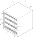
- FIG. 9 is a perspective view of a modified example of a suction rotor.
- FIG. 10(A) is a perspective view of a conventional dehumidification device, and
- FIG. 10(B) is a front view of a conventional adsorption rotor.
- the adsorption filter 1 is used primarily for dehumidification in which water in a gas to be processed, such as outside air, is adsorbed by an adsorbent and removed from the gas to be processed.
- 4 to 6 show a schematic configuration of the suction rotor 10 or the suction processing apparatus 100 according to an embodiment of the present disclosure.
- the adsorption treatment device 100 is a device that continuously removes moisture from the gas to be treated by supplying the gas to be treated to a rotating adsorption rotor 10, and a desiccant type dehumidification device is an example of its application. I can do it.
- the adsorption filter 1, adsorption rotor 10, and adsorption processing apparatus 100 of this embodiment are particularly suitable for dehumidifying a large amount of gas to be processed in buildings, condominiums, hospitals, factories, commercial facilities, and the like. Note that the use of the adsorption filter 1, adsorption rotor 10, and adsorption processing device 100 of this embodiment is not limited to dehumidification.
- an adsorption filter 1 houses an adsorption element 2 in which an adsorbent is supported on a base material made of nonwoven fabric (hereinafter referred to as "nonwoven fabric base material"), and an adsorption element 2. It includes a casing 3 and a support body 4 that holds the shape of the adsorption element 2.
- the casing 3 has a rectangular parallelepiped outer shape in this embodiment, although it is not particularly limited.
- the inside of the casing 3 is a cavity having a rectangular parallelepiped shape.
- the casing 3 has an opening communicating with an internal cavity on a pair of mutually opposing surfaces among the six surfaces.
- a pair of mutually opposing openings in the casing 3 are gas flow ports 30 .
- the gas to be treated and the regeneration gas are introduced into the casing 3 through one gas flow port 30 and are discharged from the casing 3 through the other gas flow port 30.
- the pair of gas flow ports 30 are not particularly limited, but in this embodiment, both have a rectangular outer shape and the same size.
- At least one of the four sides on which the pair of gas flow ports 30 are not formed is a removable lid or an openable lid. Thereby, the adsorption element 2 can be easily taken in and out of the casing 3.
- the material of the casing 3 is not particularly limited as long as the casing 3 exhibits sufficient strength and heat resistance during use; for example, metal materials such as stainless steel and aluminum, as well as acrylic, bakelite, melanin, etc. Examples include resin materials.
- the size of the casing 3 is appropriately set depending on the number and size of the adsorption elements 2 accommodated in the casing 3.
- the number of adsorption elements 2 accommodated in the casing 3 is one in this embodiment, it may be plural.
- a partition plate (not shown) is provided in the casing 3 and arranged adjacently. It is preferable to interpose a partition plate between the two adsorption elements 2. Thereby, it is possible to suppress the adsorption elements 2 from coming into contact with each other or rubbing against each other within the casing 3.
- the adsorption element 2 is housed in the casing 3 in close contact with the inner surface of the casing 3.
- the adsorption element 2 is formed into a pleat shape from a strip having a predetermined width, thickness, and length.
- the adsorption element 2 has a shape in which the strip-like material is folded in a zigzag manner, and is folded over and over again, and the shape is maintained.
- the adsorption element 2 includes a first bent portion 20 that protrudes convexly in one direction, a second bent portion 21 that protrudes convexly in another direction opposite to the one direction, and a first bent portion 20. and/or a straight portion 22 continuous to the second bent portion 21.
- the number of folded layers of the adsorption element 2 is not particularly limited, as long as it includes at least one first folded part 20 and at least one second folded part 21.
- the adsorption element 2 is housed in the casing 3 so that the gas to be treated and the regenerating gas introduced into the casing 3 cross over the adsorption element 2 and pass through the adsorption element 2 with low pressure loss.
- the first bent portion 20 faces toward one gas flow port 30 of the casing 3
- the second bent portion 21 faces toward the other gas flow port 30 of the casing 3. It is housed in the casing 3 so that the plane passing through the apex of each first bent part 20 and the plane passing through the apex of each second bent part 21 are perpendicular to the ventilation direction F. There is.
- the gas to be treated and the regenerating gas introduced into the casing 3 may cross the first bent portion 20 and the second bent portion 21 of the adsorption element 2, or may cross the first bent portion 20 and the second bent portion 21 of the adsorption element 2.
- the flow changes direction toward the straight portion 22 between the bent portions 21 and crosses it, and passes through the adsorption element 2 . Therefore, in the adsorption element 2, the gas to be treated and the regeneration gas are in good contact with not only the adsorbent on the surface side but also the adsorbent inside, and the contact efficiency between the gas to be treated and the regeneration gas and the adsorbent is high.
- the adsorption element 2 can effectively adsorb moisture in the gas to be treated using the adsorbent, so that dehumidification performance can be improved.
- the adsorption element 2 can effectively desorb moisture from the adsorbent with the regeneration gas, and the adsorption material can be regenerated with the regeneration gas at low temperature and low airflow, so the energy consumption during regeneration is reduced. Can improve efficiency.
- the adsorption element 2 is housed in the casing 3 such that the plurality of straight portions 22 are parallel or substantially parallel to the ventilation direction F (direction from one gas distribution port 30 of the casing 3 to the other gas distribution port 31). ing. Therefore, compared to the case where the adsorption element 2 is housed in the casing 3 so that the plurality of straight parts 22 are perpendicular to the ventilation direction F, when the gas to be treated or the regeneration gas passes through the adsorption element 2, Pressure loss can be reduced.
- the size of the adsorption element 2, that is, the height, width, and length are not particularly limited.
- the length of the adsorption element 2 (the size in the direction (depth direction) from one gas distribution port 30 to the other gas distribution port 31, and the length from the tip of the first bent portion 20 to the second bent portion
- the length (to the tip of the portion 21) is preferably 100 mm or more and 500 mm or less, more preferably 150 mm or more and 350 mm or less. Since the length of the adsorption element 2 is 100 mm or more, the adsorption element 2 can adsorb moisture on a large amount of gas to be treated. By setting the length of the adsorption element 2 to 500 mm or less, it is possible to suppress the adsorption rotor 10 from increasing in size.
- the adsorbent that constitutes the adsorption element 2 is a porous metal complex (MOF).
- Porous metal complexes (or porous coordination polymers) are porous structures that are self-assembled by combining metal ions that can take various coordination forms and organic ligands that have two or more coordination sites. It is the material.
- a framework structure is constructed by cross-linking metal ions that serve as nodes with organic ligands, and the voids within this framework act as spaces for absorbing water.
- Porous metal complexes are usually synthesized by reaction in solution. That is, a crystalline compound can be obtained by dissolving a compound having a metal ion source and an organic ligand in a solvent such as water and/or an organic solvent and heating the solution. Immediately after synthesis, solvent molecules are included within the lattice of the framework, but by removing these solvent molecules, it becomes a porous material.
- Porous metal complexes have a higher specific surface area and a sharper pore distribution than inorganic porous materials such as silica gel, zeolite, and activated carbon, so they can adsorb water in the gas to be treated at a faster rate and with less adsorption. It is characterized by the large amount of water it can produce. In addition, since it is possible to adsorb and desorb moisture with a weak bonding force, the adsorption heat generated when adsorbing moisture in the gas to be treated is small, and the adsorbed moisture can be desorbed even at low regeneration gas temperatures. Therefore, it has the characteristic that the energy required for reproduction is low.
- Metal ions constituting the porous metal complex are not particularly limited, but include, for example, titanium ions, manganese ions, iron ions, cobalt ions, nickel ions, copper ions, zinc ions, aluminum ions, zirconium ions, etc. can be mentioned.
- titanium ions, iron ions, manganese ions, copper ions, zinc ions, aluminum ions, and zirconium ions, which have low toxicity, can be preferably mentioned in consideration of environmental pollution.
- Examples of the compound having an organic ligand include, but are not limited to, terephthalic acid, isophthalic acid, 2-amino terephthalic acid, 2,5-diaminoterephthalic acid, 2,5-dihydroxyterephthalic acid, 1 , 4-naphthalenedicarboxylic acid, 2,6-naphthalenedicarboxylic acid, 4,4'-biphenyldicarboxylic acid, 3,3'-biphenyldicarboxylic acid, fumaric acid, 1H-pyrazole-3,5-dicarboxylic acid, 2,5 - dicarboxylic acids such as furandicarboxylic acid; tricarboxylic acids such as trimesic acid; tetracarboxylic acids such as azobenzene-3,3'-5,5'-tetracarboxylic acid; and imidazoles such as 2-methylimidazole. .
- Porous metal complexes are not particularly limited, but include, for example, porous metal complexes composed of aluminum ions and 2,5-furandicarboxylic acid, aluminum ions and 1H-pyrazole-3,5-dicarboxylic acid. porous metal complexes composed of iron ions and terephthalic acid; porous metal complexes composed of iron ions and trimesic acid; porous metal complexes composed of titanium ions and terephthalic acid.
- a porous metal complex composed of zirconium ions and terephthalic acid a porous metal complex composed of zirconium ions and fumaric acid, a porous metal complex composed of zirconium ions and 2-aminoterephthalic acid, a porous metal complex composed of zirconium ions and 2-aminoterephthalic acid, titanium ions and -Porous metal complex composed of aminoterephthalic acid, iron ion and porous metal complex composed of azobenzene-3,3'-5,5'-tetracarboxylic acid, aluminum ion and 1H-pyrazole-3,5 - porous metal complexes composed of dicarboxylic acids, etc. Even if the porous metal complexes are the same, the BET specific surface area of these porous metal complexes varies depending on the synthesis method and purity.
- the porous metal complex is not particularly limited, but preferably has open metal sites from the viewpoint of exhibiting higher moisture adsorption performance. Open metal sites exhibit high adsorption activity. Therefore, a porous metal complex having open metal sites has a very high rate of adsorption of moisture in the gas to be treated, and exhibits higher moisture adsorption performance than other porous metal complexes.
- One embodiment of the open metal site is, for example, an embodiment in which the metal ion is coordinately unsaturated and has at least one vacant site in its coordination state, that is, a coordinately unsaturated site.
- a porous metal complex having coordination unsaturated sites is one in which the ligand of the metal ion (Fe ion in Figure 7) is unsaturated, and the metal ion has one or more vacant coordination child (vacant site). Water molecules are adsorbed to these empty sites. Therefore, by using a porous metal complex having coordination unsaturated sites as an adsorbent, water in the gas to be treated can be effectively adsorbed, and high dehumidification performance for the gas to be treated can be exhibited.
- Porous metal complexes having coordination unsaturated sites include, but are not limited to, porous metal complexes composed of iron ions and azobenzene-3,3'-5,5'-tetracarboxylic acid (PCN250 or MIL127).
- chromium and terephthalic acid An example is a porous metal complex (MIL101) composed of an acid, and among these, PCN250 is preferable because it has a fast adsorption/desorption rate and uses a metal with low water resistance and toxicity.
- porous metal complexes having higher moisture adsorption performance include porous metal complexes having a hydroxyl group (OH-) near the metal.
- a porous metal complex having a hydroxy group near the metal has a hydroxy group (OH-) in the metal core unit, as shown in FIG.
- the porous metal complex has a hydroxyl group in the metal core unit, it exhibits excellent adsorption activity for water molecules. Therefore, a porous metal complex having a hydroxyl group in the metal core unit has a very high rate of adsorption and desorption of moisture in the gas to be treated, and exhibits higher moisture adsorption performance than other porous metal complexes. Therefore, by using a porous metal complex having a hydroxyl group in the metal core unit as an adsorbent, water in the gas to be treated can be effectively adsorbed, and high dehumidification performance for the gas to be treated can be exhibited.
- the metal core unit refers to a metal cluster that constitutes a porous metal complex represented by MxOyHz (x, y are integers other than 0, z is an integer including 0).
- Some of the oxygen atoms in the metal core unit MxOyHz are carboxyl group oxygen atoms of organic ligands, and the metal core unit forms a framework by sharing oxygen atoms with the organic ligands.
- porous metal complex having a hydroxyl group in the metal core unit examples include, but are not particularly limited to, a porous metal complex composed of zirconium ions and fumaric acid (MOF801), aluminum ions and 1H-pyrazole-3,5-dicarboxylic acid, etc.
- a porous metal complex composed of an acid.
- the adsorption filter 1 using the above-mentioned porous metal complex having open metal sites or a porous metal complex having a hydroxyl group in the metal core unit as an adsorbent can generate air with low humidity, and is therefore suitable for use in clean rooms, for example. It can be suitably used in a low dew point type dehumidification device.
- the shape of the porous metal complex is not particularly limited, and can be in various shapes such as powder or granules.
- the adsorbent may contain one or more porous metal complexes.
- the size of the adsorbent is not particularly limited, but is preferably 0.5 ⁇ m or more and 150 ⁇ m or less, more preferably 1 ⁇ m or more and 100 ⁇ m or less.
- the size of the adsorbent is 0.5 ⁇ m or more, it is possible to make it difficult for the adsorbent to fall off in the adsorption element 2, and it is possible to increase the contact efficiency of the adsorbent with the gas to be treated or regenerated gas. .
- the size of the adsorbent can be measured by the D50 value of a laser diffraction particle size analyzer or the average particle diameter by a scanning electron microscope.
- the pores of the adsorbent may be one-dimensional pores or three-dimensional pores, but from the viewpoint that the adsorption rate of moisture in the gas to be treated is fast and it is easy to adsorb moisture.
- the use of porous metal complexes having one-dimensional pores and open metal sites is preferred.
- porous metal complexes having one-dimensional pores include the above-mentioned MOF74 and MOF303.
- examples of porous metal complexes having open metal sites include the above-mentioned MOF74 and PCN250.
- the crystallite size of the adsorbent is small in order to easily adsorb moisture to the inside of the pores.
- MOF801 mentioned above can be cited as an example.
- the adsorbent is not particularly limited, but preferably is a porous metal complex having a pore diameter of 3.0 ⁇ or more and 10 ⁇ or less, more preferably 3.5 ⁇ or more and 8 ⁇ or less.
- a porous metal complex with a pore diameter of 3.0 ⁇ or more and 10 ⁇ or less has good adsorption performance and can easily desorb adsorbed water from the adsorbent during regeneration.
- the pore diameter of the adsorbent can be obtained by measuring the cage diameter or window diameter of the pores by X-ray structural analysis.
- the specific surface area of the adsorbent measured by the BET method is not particularly limited, but is preferably 200 m 2 /g or more and 2500 m 2 /g or less, more preferably 300 m 2 /g or more. It is 2000 m 2 /g or less.
- BET specific surface area is not particularly limited, but is preferably 200 m 2 /g or more and 2500 m 2 /g or less, more preferably 300 m 2 /g or more. It is 2000 m 2 /g or less.
- the content of the adsorbent in the adsorption element 2 is not particularly limited, but is preferably 15% by mass or more and 80% by mass or less, more preferably 20% by mass or more and 70% by mass or less.
- the content of the adsorbent is 15% by mass or more, the efficiency of contact between the gas to be treated or the regeneration gas and the adsorbent can be increased.
- By having an adsorbent content of 80% by mass or less it is possible to make it difficult for the adsorbent to fall off in the adsorption element 2, and to reduce the pressure loss when the gas to be treated or the regeneration gas passes through the adsorption element 2. can be reduced.
- the adsorbent is not particularly limited, it is preferable to impregnate water vapor or water into its pores before supporting it on a nonwoven fabric base material by adhesion with a binder, which will be described later. This prevents the binder from existing in the pores of the adsorbent and clogging the pores, thereby suppressing the deterioration of the adsorption performance of the moisture in the gas to be processed by the adsorbent in the adsorption element 2. I can do that.
- the adsorbent is not particularly limited, the adsorbent may have adsorption performance for carbon dioxide and aldehydes such as formaldehyde and acetaldehyde by supporting an amine compound on a porous metal complex.
- the base material constituting the adsorption element 2 is a single nonwoven fabric or a laminate of multiple nonwoven fabrics.
- the fibers constituting the nonwoven fabric are not particularly limited, and include, for example, phenolic resin fibers, polyphenylene ether fibers, flame-resistant polyphenylene ether fibers, polyacrylonitrile fibers, flame-resistant polyacrylonitrile fibers, pitch fibers, flame-resistant pitch fibers, and aramid fibers. Examples include PET fibers, glass fibers, ceramic fibers, carbon fibers, activated carbon fibers, stainless steel fibers, aluminum fibers, and other metal fibers.
- nonwoven fabrics made of phenolic fibers phenolic fiber nonwoven fabrics
- nonwoven fabrics made of polyphenylene ether fibers polyphenylene ether fiber nonwoven fabrics
- nonwoven fabrics made of flame resistant polyphenylene ether fibers flame resistant polyphenylene ether fiber nonwoven fabrics
- flame resistant acrylonitrile fibers flame resistant polyphenylene ether fiber nonwoven fabrics
- flame resistant acrylonitrile fibers flame resistant polyphenylene ether fiber nonwoven fabrics
- flame resistant acrylonitrile fibers flame resistant polyphenylene ether fiber nonwoven fabrics
- flame resistant acrylonitrile fibers flame resistant polyphenylene ether fiber nonwoven fabrics
- flame resistant acrylonitrile fibers flame resistant polyphenylene ether fiber nonwoven fabrics
- flame resistant acrylonitrile fibers flame resistant polyphenylene ether fiber nonwoven fabrics
- flame resistant acrylonitrile fibers flame resistant polyphenylene ether fiber nonwoven fabrics
- flame resistant acrylonitrile fibers flame resistant polyphenylene ether fiber nonwoven
- the cross-sectional shape of the above-mentioned fibers may be a general shape such as a circle or an ellipse, or an irregular shape such as a star shape or a Y-shape.
- the average fiber diameter of the fibers constituting the nonwoven fabric is not particularly limited, but is preferably 10 ⁇ m or more and 100 ⁇ m or less, more preferably 15 ⁇ m or more and 60 ⁇ m or less.
- the average fiber diameter is 10 ⁇ m or more, the gaps between the fibers of the nonwoven fabric base material do not become too narrow, so that the pressure loss when the gas to be treated or the regeneration gas passes through the adsorption element 2 can be reduced.
- By having an average fiber diameter of 100 ⁇ m or less it is possible to make it difficult for the adsorbent to fall off in the adsorption element 2.
- the average fiber diameter is determined by observing a microscopic image of the fiber using a scanning electron microscope (product name SU1510, manufactured by Hitachi High-Technologies), reading the diameters of 100 or more fibers from the microscopic image, and averaging the read fiber diameters. can be found.
- a scanning electron microscope product name SU1510, manufactured by Hitachi High-Technologies
- the method for producing the nonwoven fabric base material is not particularly limited, and examples include spunbond method, melt blow method, spunlace method, needle punch method, thermal bond method, and chemical bond method. Among these, it is preferable to use a needle-punched nonwoven fabric produced by the needle-punching method because it provides suitable voids that can support the adsorbent.
- the thickness of the nonwoven fabric base material is: Although not particularly limited, it is preferably 4 mm or more and 50 mm or less, more preferably 10 mm or more and 40 mm or less.
- a thickness of the nonwoven fabric base material is 4 mm or more, sufficient strength of the adsorption element 2 can be ensured.
- the thickness of the nonwoven fabric base material is 50 mm or less, the adsorption element 2 can be easily processed into a pleated shape, and pressure loss when the gas to be treated or the regeneration gas passes through the adsorption element 2 can be reduced.
- the basis weight of the nonwoven fabric base material (if the nonwoven fabric base is a single piece of nonwoven fabric, the basis weight of the nonwoven fabric alone; if the nonwoven fabric base material is a laminate of multiple nonwoven fabrics, the total basis weight of the laminate) is: Although not particularly limited, it is preferably 300 g/m 2 or more and 5000 g/m 2 or less, more preferably 600 g/m 2 or more and 4000 g/m 2 or less.
- the basis weight of the nonwoven fabric base material is 300 g/m 2 or more, the strength of the adsorption element 2 can be sufficiently ensured, and the contact efficiency between the gas to be treated or the regeneration gas and the adsorbent can be increased.
- pressure loss when the gas to be treated or the regeneration gas passes through the adsorption element 2 can be reduced.
- the adsorption element 2 is manufactured by the procedure described below. First, an adsorbent and a binder are dispersed in water to produce a slurry.
- the binder is not particularly limited as long as it can bond the adsorbent to the nonwoven fabric substrate, but it is preferable to use a water-repellent binder.
- water-repellent binders include organic binders having structural units derived from styrene and/or acrylic.
- the form of the binder is not particularly limited, it is preferable to use an emulsion form.
- the contents of the adsorbent and binder in the slurry are not particularly limited, but the adsorbent is, for example, 5% by mass or more and 50% by mass or less, and the binder is, for example, 1% by mass or more and 40% by mass or less.
- the temperature of the slurry is not particularly limited, but is, for example, 5° C. or higher and 35° C. or lower.
- the nonwoven fabric base material is sufficiently immersed in the slurry to incorporate the slurry not only onto the surface of the nonwoven fabric base material but also into its interior. Then, the nonwoven fabric base material that has been immersed in the slurry is squeezed under pressure to allow the slurry to sufficiently penetrate inside the nonwoven fabric base material, and unnecessary slurry is removed from the nonwoven fabric base material to form a slurry that is applied to the nonwoven fabric base material. Adjust amount.
- the proportion of the slurry applied to the nonwoven fabric base material is not particularly limited, but is preferably 20% by mass or more and 95% by mass or less, more preferably 25% by mass or more and 90% by mass or less.
- the squeezed nonwoven fabric base material is dried to remove moisture contained in the nonwoven fabric base material.
- the drying temperature is not particularly limited, but is, for example, 5° C. or higher and 200° C. or lower, and drying can be performed using air at about 20° C. and low humidity, for example.
- the adsorption element 2 is manufactured by forming the nonwoven fabric base material carrying the dried adsorbent into a pleat shape.
- the nonwoven fabric base material is formed into a pleat shape in a semi-dry state where the nonwoven fabric base material is completely dried. The nonwoven substrate may then be completely dried.
- the slurry penetrates into the inside of the nonwoven fabric base material, and the slurry adheres not only to the fibers on the surface side of the nonwoven fabric base material but also to the fibers inside the nonwoven fabric base material. , the slurry between the fibers is extruded and removed from the nonwoven substrate.
- the adsorbent is supported on the surface of the constituent fibers throughout the nonwoven fabric base material by adhesion with the binder, while being suppressed from existing between the fibers of the nonwoven fabric base material.
- the air permeability of the adsorption element 2 is increased, and pressure loss when the gas to be treated and the regeneration gas pass through the adsorption element 2 can be reduced.
- the support body 4 is provided within the casing 3 in order to hold the pleated adsorption element 2 in a stable state without losing its shape.
- the support body 4 is not particularly limited, but in this embodiment, it is made of a net-like body in which a corrugated wire mesh 41 is sandwiched between two flat wire meshes 40.
- the support body 4 is sandwiched between a plurality of straight portions 22 of the pleated adsorption element 2 arranged at intervals.
- the thickness of the support 4 is not particularly limited, but is, for example, 5 mm or more and 25 mm or less.
- the material of the support 4 is not particularly limited as long as it has sufficient strength, heat resistance, chemical resistance, etc. under the usage conditions of the adsorption filter 4, and examples include metal materials such as stainless steel and aluminum, as well as acrylic and Bakelite. Examples include resin materials such as , melanin, and the like.
- the support body 4 does not necessarily need to be composed of a plurality of net-like bodies, and its form is not limited as long as it can hold the pleated adsorption element 2 in a stable state without losing its shape.
- the adsorption filter 1 having the above structure preferably has a pressure loss of 2 kPa or less, more preferably 1.5 kPa or less, and even more preferably 1.0 kPa or less. Thereby, the gas to be treated can be efficiently passed through the adsorption filter 1.
- the pressure loss can be determined by setting the adsorption filter 1 in a ventilation pressure loss measurement jig and measuring the pressure loss when ventilation is passed through one gas flow port 30 at a wind speed of 2.0 m/s.
- the suction rotor 10 has a hollow, generally annular shape having an inner diameter and an outer diameter when viewed in cross section, and has a predetermined height.
- the suction rotor 10 is installed in the processing chamber 101 so as to be rotationally driven around the rotation axis L.
- the adsorption rotor 10 is installed in the processing chamber 101 so that the rotation axis thereof faces vertically so that the gas to be processed is introduced and discharged at each of the inner and outer peripheries.
- the rotation axis of the suction rotor 10 passes through the center in a cross-sectional view.
- the adsorption rotor 10 includes a plurality of the above-mentioned adsorption filters 1.
- the plurality of adsorption filters 1 are arranged along the circumferential direction around the rotation axis of the adsorption rotor 10.
- the plurality of adsorption filters 1 are arranged such that the pair of gas flow ports 30 of the casing 3 face the outer and inner peripheries of the adsorption rotor 10 .
- the plurality of adsorption filters 1 are arranged in a fixed state so as to form a plurality of vertical stages (in this embodiment, two stages above and below), they do not necessarily need to be arranged in a plurality of stages.
- the suction rotor 10 includes a pair of discs 5A and 5B made of stainless steel, for example.
- a pair of disks 5A and 5B sandwich the plurality of adsorption filters 1 from above and below.
- the pair of disks 5A and 5B are hollow and generally annular in shape and have an inner diameter and an outer diameter when viewed in cross section.
- the pair of disks 5A and 5B are arranged parallel to each other so that the rotation axis of the suction rotor 10 passes through the center in a cross-sectional view.
- the central openings of the pair of disks 5A, 5B communicate with the inner cavities of the plurality of adsorption filters 1 arranged in a cylindrical shape.
- the suction rotor 10 includes a plurality of partitions 7 that partition the space between the pair of disks 5A, 5B into a plurality of mutually independent spaces in the circumferential direction.
- An adsorption filter 1 is housed airtightly between two adjacent partitions 7 between a pair of disks 5A and 5B with a sealing member 6 made of, for example, rubber interposed therebetween.
- the plurality of partitions 7 extend in the radial direction from the inner circumferential edge to the outer circumferential edge of the pair of disks 5A, 5B, and are arranged at intervals in the circumferential direction. Further, the plurality of partitions 7 are erected between the pair of disks 5A and 5B.
- the gas to be treated flowing in from the inner or outer circumference of the adsorption rotor 10 passes through each adsorption filter 1 between the pair of disks 5A and 5B and between the plurality of partitions 7.
- the partition 7 includes a main body portion 70 and a pair of seal portions 71A and 71B.
- the main body portion 70 is made of stainless steel, for example.
- the upper and lower ends of the main body portion 70 are in airtight contact with the pair of discs 5A and 5B.
- the seal parts 71A and 71B are made of rubber, for example.
- the seal portions 71A and 71B are attached to both side edges of the main body portion 70 using, for example, adhesive.
- the upper and lower ends of the seal portions 71A, 71B are in airtight contact with the pair of disks 5A, 5B.
- a portion of the seal portion 71A attached to the inner side edge of the main body portion 70 protrudes inward from the inner peripheral edges of the pair of discs 5A and 5B.
- a portion of the seal portion 71B attached to the outer side edge of the main body portion 70 protrudes outward from the outer peripheral edge of the pair of disks 5A, 5B.
- the adsorption processing apparatus 100 includes the above-mentioned adsorption rotor 10 installed in a processing chamber 101.
- the suction rotor 10 is rotationally driven around the rotation axis L by receiving the rotational driving force of the motor 9, for example.
- the adsorption rotor 10 moves a portion in the circumferential direction to an adsorption zone 102 where the gas to be processed is adsorbed, and the remaining portion in the circumferential direction moves to the adsorption zone 102 where the adsorption process is performed using regeneration gas. Move to zone 103.
- the adsorption processing apparatus 100 includes a flow path through which a gas to be processed supplied into the processing chamber 101 flows into and out of an adsorption filter 1 that is a part of an adsorption rotor 10 that rotates within the processing chamber 101, and A supply flow path forming member 8 is provided for forming a flow path through which regeneration gas flows into and out of another part of the adsorption filter 1 of the adsorption rotor 10.
- the supply flow path forming member 8 includes a first flow path forming member 80 , a second flow path forming member 81 , a third flow path forming member 82 , and a zone dividing member 83 .
- the first flow path forming member 80 has a cylindrical shape, and the gas to be treated flows through the inside thereof.
- the first flow path forming member 80 is provided so as to penetrate through the ceiling of the processing chamber 101, and the lower end of the first flow path forming member 80 is in contact with the disc 5A of the adsorption rotor 10 in an airtight manner so that the disc 5A can rotate. There is.
- the inner cavity of the first flow path forming member 80 communicates with the inner cavity of the adsorption rotor 10 via the central opening of the disk 5A.
- the first flow path forming member 80 introduces the gas to be treated, which flows from the outside of the adsorption rotor 10 into the processing chamber 101, passes through the adsorption filter 1, and flows out into the inside of the adsorption rotor 10, into the inside through an opening 800 at the lower end. , and is discharged to the outside of the processing chamber 101 from the opening 801 at the upper end.
- the second flow path forming member 81 has a cylindrical shape, and the regeneration gas flows through the inside thereof.
- One end of the second flow path forming member 81 is bent into an L shape and is provided so as to penetrate the side wall of the first flow path forming member 80 .
- An opening 810 at one end of the second flow path forming member 81 is located outside the processing chamber 101 and introduces the regeneration gas into the second flow path forming member 81 .
- the other end of the second flow path forming member 81 is arranged in a cavity inside the adsorption rotor 10 .
- the opening 811 at the other end of the second flow path forming member 81 is parallel to the vertical direction and faces the inner periphery of the adsorption rotor 10, and is connected to the communication port 30 of the adsorption filter 1 that moves in the circumferential direction as the adsorption rotor 10 rotates. to oppose.
- the opening 811 at the other end of the second flow path forming member 81 discharges the regeneration gas flowing inside the second flow path forming member 81 toward the inner periphery of the adsorption filter 1 of the adsorption rotor 10 .
- the third flow path forming member 82 has a cylindrical shape, and the regeneration gas flows through the inside thereof.
- One end of the third flow path forming member 82 is disposed outside the outer periphery of the adsorption rotor 10 .
- the opening 820 at one end of the third flow path forming member 82 is parallel to the vertical direction and faces the outer periphery of the adsorption rotor 10, and the opening 820 at the other end of the second flow path forming member 81 and the adsorption rotor 10 are sandwiched therebetween. face each other.
- the opening 820 at one end of the third flow path forming member 82 faces the flow port 30 of the adsorption filter 1 that moves in the circumferential direction due to the rotation of the adsorption rotor 10.
- the opening 821 at one end of the third flow path forming member 82 introduces the regenerating gas that flows from the inside of the adsorption rotor 10, passes through the adsorption filter 1, and flows out to the outside into the third flow path forming member 82.
- the other end of the third flow path forming member 82 is provided so as to penetrate the side wall of the processing chamber 101 .
- the opening 821 at the other end of the third flow path forming member 82 is located outside the processing chamber 101 and discharges the regeneration gas flowing inside the third flow path forming member 82 to the outside of the processing chamber 101 .
- the zone dividing member 83 includes a pair of inner curved portions 830 provided at the other end of the second channel forming member 81 and a pair of outer curved portions 831 provided at one end of the third channel forming member 82. including.
- the inner curved portion 830 is curved so as to face the inner circumference of the suction rotor 10
- the outer curved portion 831 is curved so as to face the outer circumference of the suction rotor 10 .
- the curved portions 831 are parallel to each other.
- the upper and lower ends of the inner curved portion 830 and the outer curved portion 831 are in contact with the discs 5A, 5B of the suction rotor 10 in an airtight manner so that the discs 5A, 5B can rotate.
- the plurality of suction filters 1 and the plurality of partitions 7 move in the circumferential direction of the suction rotor 10.
- the inner seal part 71A and the outer seal part 71B of some of the partitions 7 are in airtight contact with the inner curved part 830 and the outer curved part 831 on the upstream side in the rotational direction, respectively.
- the inner seal part 71A and the outer seal part 71B of some of the partitions 7 move while being in airtight contact with the inner curved part 830 and the outer curved part 831 on the downstream side in the rotational direction, respectively.
- the adsorption filter 1 which is moving to the adsorption zone 102 which does not communicate with the third flow path forming member 82 and thus becomes an adsorption zone 102 .
- the plurality of adsorption filters 1 of the adsorption rotor 10 alternately move between the adsorption zone 102 and the desorption zone 103 as the adsorption rotor 10 rotates.
- the adsorption processing of moisture in the gas to be processed will be explained.
- the gas to be treated is introduced into the adsorption filter 1 that is moving to the adsorption zone 102 of the adsorption rotor 10.
- the adsorption filter 1 adsorbs moisture in the gas to be treated using an adsorbent while the gas to be treated passes through the adsorption element 2 . Thereby, the gas to be processed is dehumidified.
- the dehumidified gas to be processed is discharged from the inner periphery of the adsorption rotor 10 , introduced into the first flow path forming member 80 , and discharged to the outside of the processing chamber 101 by the first flow path forming member 80 .
- a regeneration gas such as heated air is supplied from the inner circumference of the adsorption rotor 10 in the desorption zone 103 in the processing chamber 101 by the second flow path forming member 81, and the regeneration gas is moved to the desorption zone 103 of the adsorption rotor 10. into the adsorption filter 1.
- the adsorption filter 1 when the regeneration gas passes through the adsorption element 2, moisture adsorbed by the adsorbent is desorbed by the regeneration gas. Thereby, the adsorption element 2 of the adsorption filter 1 is regenerated. Then, the regeneration gas containing moisture is discharged from the outer periphery of the adsorption rotor 10, introduced into the third flow path forming member 82, and discharged to the outside of the processing chamber 101 by the third flow path forming member 82.
- the adsorption process is performed on the gas to be treated by the adsorption filter 1 that moves to the adsorption zone 102 as the adsorption rotor 10 rotates, and the adsorption process that moves to the desorption zone 103 after the adsorption process 1 is subjected to a desorption process for the adsorbed moisture.
- the suction rotor 10 rotates around the rotation axis L, the suction filter 1 alternately moves between the suction zone 101 and the desorption zone 103. Therefore, in the adsorption processing apparatus 100, the adsorption of moisture in the gas to be treated and the regeneration process of the adsorption filter 1 that has adsorbed the moisture are performed continuously.
- the pleated adsorption element 2 has its first bent portion 20 connected to one gas flow port 30 of the casing 3. It is housed in the casing 3 with the second bent portion 21 facing the other gas flow port 30 of the casing 3 . Therefore, the gas to be treated and the regeneration gas pass through the adsorption element 2 while intersecting a portion of the adsorption element 2 (the bent portions 20 and 21 and the straight portion 22).
- the gas to be treated and the regeneration gas come into good contact not only with the adsorbent supported on the surface side of the adsorption element 2 but also with the adsorbent supported inside the adsorption element 2. Therefore, according to the above-described adsorption filter 1, adsorption rotor 10, and adsorption processing apparatus 100, the contact efficiency between the gas to be treated and the adsorbent is high, so that the dehumidification performance can be improved. In addition, the contact efficiency between the regenerating gas and the adsorbent is high, and moisture can be desorbed from the adsorbent with the regenerating gas at a lower temperature and with a lower air volume than when the conventional adsorption element has a honeycomb structure. Therefore, according to the above-described adsorption filter 1, adsorption rotor 10, and adsorption processing device 100, energy efficiency during regeneration can be improved.
- the adsorbent is carried on the surface of the fibers constituting the nonwoven fabric base material, and the adsorbent material is supported on the surface of the fibers constituting the nonwoven fabric base material, and the adsorbent material is supported on the surface of the fibers constituting the nonwoven fabric base material.
- Existence is suppressed. Thereby, the air permeability of the adsorption element 2 is increased, and pressure loss when the gas to be treated and the regeneration gas pass through the adsorption element 2 can be reduced.
- the gas to be treated or regenerated gas can be passed through with low pressure loss. can be done.
- the porous metal complex used in the adsorption material has a high adsorption speed of moisture in the air and a small amount of moisture that can be adsorbed. Since there is a large amount of water, it is possible to adsorb more water in the gas to be treated than conventional and commonly used silica gel. Therefore, according to the above-described adsorption filter 1, adsorption rotor 10, and adsorption processing device 100, the dehumidification performance can be further improved.
- adsorption filter 1, adsorption rotor 10, and adsorption processing device 100 can be suitably used, for example, in a low dew point dehumidification device for a clean room.
- the porous metal complex used in the adsorption material has a lower temperature than the conventional and commonly used silica gel. Moisture can be desorbed from the adsorbent with regeneration gas. Therefore, according to the above-described adsorption filter 1, adsorption rotor 10, and adsorption processing device 100, energy efficiency during regeneration can be improved and energy saving is possible.
- the adsorbent is supported on the nonwoven fabric base material in the adsorption element 2 by adhesion with a binder, but as a modified example, the adsorbent is directly synthesized with the nonwoven fabric base material, so that the adsorbent is supported on the nonwoven fabric base material. You may let them.
- Direct synthesis of adsorbents onto nonwoven substrates involves (1) a layer-by-layer method by alternately immersing the nonwoven substrate in metal and ligand solutions; (2) synthesis of metal and ligands; There is a method in which a nonwoven fabric base material is synthesized by immersing it in a mixed solution, and in some cases, after the immersion, a skeleton is formed using heating, pressure, or microwaves.
- the adsorption rotor 10 is installed in the processing chamber 101 so that the rotation axis L points in the vertical direction; You may.
- the suction rotor 10 is formed by connecting a plurality of suction filters 1 arranged along the circumferential direction around the rotation axis L, as shown in FIG.
- the adsorption filter 1 includes an adsorption element 2 formed in a pleated shape and a casing 3 that accommodates the adsorption element 2, as in the embodiment described above.
- the casing 3 does not have a rectangular parallelepiped shape but a quadrangular prism shape with a trapezoidal cross section.
- the inside of the casing 3 is a cavity having a rectangular parallelepiped shape.
- gas flow ports 30 each communicating with an internal cavity are formed on a pair of trapezoidal faces facing each other.
- the adsorption element 2 is housed in the casing 3 in close contact with the inner surface of the casing 3.
- the adsorption filter 1 of the adsorption rotor 10 alternately moves between the adsorption zone 102 and the desorption zone 103 due to the rotation of the adsorption rotor 10.
- the adsorption zone 102 and the desorption zone 103 are separated by a flow path forming member (not shown).
- the gas to be treated that is supplied to the adsorption zone 102 crosses the adsorption element 2 of the adsorption filter 1 and passes through the adsorption element 2. Adsorbs moisture. Thereby, the gas to be processed is dehumidified.
- the regeneration gas supplied to the desorption zone 103 crosses the adsorption element 2 of the adsorption filter 1 and passes through the adsorption element 2, so that the moisture adsorbed by the adsorbent is transferred to the regeneration gas. It is attached and detached by. Thereby, the adsorption element 2 of the adsorption filter 1 is regenerated.
- FIG. 9 also provides the same actions and effects as the embodiment described above.
- the adsorption filter 1, adsorption rotor 10, and adsorption processing apparatus 100 of the embodiment shown in FIG. 9 can be suitably used, for example, in a factory, etc. to dehumidify a gas to be processed with a low air volume. Note that the use of the adsorption filter 1, adsorption rotor 10, and adsorption processing device 100 is not limited to dehumidification.
- adsorption filter of the present disclosure will be shown below to specifically explain the functions and effects, but the adsorption filter of the present disclosure is not limited to the following examples.
- Example 1 In Example 1, 2.7 kg of PCN250 (solid content 72%) was soaked overnight in 5.5 kg of water as an adsorbent, and then acrylic-styrene binder A (solid content 37%) 1 was soaked as a water-resistant binder. .0 kg was added to produce a 25% solids slurry. After immersing Kynor felt (fabric weight 600 g/m 2 , fineness 10 denier, thickness 6.0 mm) in the slurry as a nonwoven fabric, excess slurry was squeezed out from the nonwoven fabric, water was evaporated, and the nonwoven fabric carrying PCN250 was prepared. Obtained.
- Kynor felt fabric weight 600 g/m 2 , fineness 10 denier, thickness 6.0 mm
- this nonwoven fabric Four sheets of this nonwoven fabric are laminated to form a nonwoven fabric base material, and after folding the nonwoven fabric base material into a pleat shape, it is heated and dried at 130°C to form a pleat shape with a height of 250 mm, width of 250 mm, and length of 200 mm.
- An adsorption element was obtained.
- the content of PCN250 in the adsorption element was 45.5% by mass.
- PCN250 was produced by the following method. 0.5 g of Fe(NO 3 ) 3.9H 2 O and 0.1 g of azobenzene-3,3'-5,5'-tetracarboxylic acid were dissolved in 20 mL of N,N-dimethylformaldehyde and 10 mL of acetic acid. PCN250 was synthesized by heating at °C for 24 hours. As a result of nitrogen adsorption measurement of the PCN250 sample, the BET specific surface area was 1227 m 2 /g.
- Example 2 2.8 kg of MOF303 (solid content 70%) was soaked overnight in 5.6 kg of water as an adsorbent, and then acrylic-styrene binder A (solid content 37%) 1 was soaked as a water-resistant binder. .0 kg was added to produce a 25% solids slurry.
- Kynor felt (fabric weight: 600 g/m 2 , fineness: 10 denier, thickness: 6.0 mm) was immersed in the slurry as a nonwoven fabric, and then the excess slurry was squeezed out from the nonwoven fabric and the water was evaporated to form a nonwoven fabric carrying MOF303. Obtained.
- this nonwoven fabric Four sheets of this nonwoven fabric are laminated to form a nonwoven fabric base material, and after folding the nonwoven fabric base material into a pleat shape, it is heated and dried at 130°C to form a pleat shape with a height of 250 mm, width of 250 mm, and length of 200 mm.
- An adsorption element was obtained.
- the content of MOF303 in the adsorption element was 45.0% by mass.
- MOF303 was manufactured by the following method. 10.4 g (43.08 mmol) of AlCl 3.6H 2 O and 7.5 g (43.08 mmol) of 1H-pyrazole-3,5-dicarboxylic acid monohydrate were mixed with 720 mL of water and 2.6 g (65 mmol) of NaOH/30 mL of water. MOF303 was synthesized by dissolving it in water and heating it at 100°C for 24 hours. As a result of nitrogen adsorption measurement of the MOF303 sample, the BET specific surface area was 1181 m 2 /g.
- Example 3 2.4 kg of MOF801 (alkali treated, solid content 85%) was soaked overnight in 6.3 kg of water as an adsorbent, and then acrylic-styrene binder A (solid content) was soaked as a water-resistant binder. 37%) was added to produce a slurry with a solids content of 25%.
- Kynor felt fabric weight 600 g/m 2 , fineness 10 denier, thickness 6.0 mm
- MOF801 alkali treated
- This nonwoven fabric Four sheets of this nonwoven fabric are laminated to form a nonwoven fabric base material, and after folding the nonwoven fabric base material into a pleat shape, it is heated and dried at 130°C to form a pleat shape with a height of 250 mm, width of 250 mm, and length of 200 mm.
- An adsorption element was obtained.
- the content of MOF801 (alkali treated) in the adsorption element was 48.0% by mass.
- MOF801 (alkali treated) was produced by the following method. 200 g (0.62 mmol) of ZrOCl 2.8H 2 O and 72 g (0.62 mmol) of fumaric acid were dissolved in 2 L of N,N-dimethylformaldehyde and 700 mL of formic acid, and the mixture was heated at 130° C. for 6 hours to synthesize MOF801. The obtained MOF801 was suspended in water (pH 3.6), and 2 wt % sodium hydrogen carbonate water was added dropwise thereto until the pH exceeded 5. Thereafter, it was washed several times with pure water to obtain a MOF801 (alkali-treated) sample. As a result of nitrogen adsorption measurement of the MOF801 (alkali-treated) sample, the BET specific surface area was 600 m 2 /g.
- MOF303 was immersed in water as an adsorbent for 24 hours, and then filtered to obtain a MOF303 sample in which water molecules were adsorbed in the pores.
- This MOF303 sample is 80% by mass (excluding water molecules), 8% by mass of aramid fibers as non-fibrillated fibers, 5% by mass of aramid fibers as fibrillated fibers, and polyvinyl having a dissolution temperature in water of 70°C as an organic binder.
- Comparative Example 2 2.7 kg of A-type silica gel (Fuji Silica Gel A-type crushed manufactured by Fuji Silysia Chemical Co., Ltd., solid content 73%) was soaked overnight in 5.8 kg of water as an adsorbent, and then acrylic was added as a water-resistant binder. - 1.0 kg of styrenic binder A (solid content 37%) was added to produce a slurry with a solid content of 25%.
- Kynor felt (fabric weight: 600 g/m 2 , fineness: 10 denier, thickness: 6.0 mm) was immersed in the slurry as a non-woven fabric, and then the excess slurry was squeezed out from the non-woven fabric, and the water was evaporated to form a non-woven fabric carrying silica gel. Obtained.
- Four sheets of this nonwoven fabric are laminated to form a nonwoven fabric base material, and after folding the nonwoven fabric base material into a pleat shape, it is heated and dried at 130°C to form a pleat shape with a height of 250 mm, width of 250 mm, and length of 200 mm.
- An adsorption element was obtained.
- the content of silica gel in the adsorption element was 47.8% by mass.
- An adsorption filter in which the adsorption elements of Examples 1 to 3 and the adsorption elements of Comparative Examples 1 to 2 were each housed closely in a casing was installed in a dynamic water vapor adsorption/desorption evaluation tester, and the dehumidification performance was evaluated.
- the ratio of the flow rate of the treated gas (air) during dehumidification to the flow rate of the regeneration gas (air) during regeneration is set to 3:1, and the dehumidification is performed at a temperature of 20°C and an absolute humidity of 6.5 g/kg.
- DA a gas to be treated at a wind speed of 2 m/sec was supplied to the adsorption element to adsorb moisture in the gas to be treated.
- Regeneration is performed by supplying regeneration gas to the adsorption element from the opposite direction to that used during dehumidification, at a temperature of 80°C to 150°C, absolute humidity, and wind speed of 2 m/sec, to remove moisture from the adsorbent. was adsorbed. Dehumidification and regeneration were performed alternately multiple times, and the average value of the absolute humidity of the gas to be treated in which moisture had been adsorbed was measured as the dehumidification performance. The results are shown in Table 1. Table 1 also shows the reduction in energy consumption during regeneration for Examples 1 to 3 and Comparative Examples 1 to 2.
- Example 2 has better dehumidification performance than Comparative Example 1. Furthermore, it is confirmed that Example 1 can maintain high dehumidification performance even when the temperature of the regeneration gas (desorption temperature) is low. Based on these facts, pleated adsorption elements have a higher contact efficiency between the gas to be treated and the adsorbent than honeycomb-structured adsorption elements, so they can achieve good dehumidification performance with a small amount of adsorbent. It can be seen that since the contact efficiency between the regeneration gas and the adsorbent is high, water can be desorbed from the adsorbent with the regeneration gas at a low temperature, and the energy efficiency during regeneration is improved.
- Examples 1 to 3 can maintain high dehumidification performance with regeneration gas at a lower temperature than Comparative Example 2. is confirmed. Therefore, by using a porous metal complex as an adsorbent, it is possible to desorb water from the adsorbent with a regeneration gas at a lower temperature than by using silica gel as an adsorbent, and the energy used during regeneration is reduced. It can be seen that the amount can be reduced and energy can be saved.
- Adsorption filter 2 Adsorption element 3 Casing 9 Motor 10
- Adsorption rotor 20 First bent part 21 Second bent part 30
- Gas flow port 100 Adsorption treatment device 102
Landscapes
- Chemical & Material Sciences (AREA)
- Engineering & Computer Science (AREA)
- Chemical Kinetics & Catalysis (AREA)
- Analytical Chemistry (AREA)
- General Chemical & Material Sciences (AREA)
- Oil, Petroleum & Natural Gas (AREA)
- Combustion & Propulsion (AREA)
- Mechanical Engineering (AREA)
- General Engineering & Computer Science (AREA)
- Separation Of Gases By Adsorption (AREA)
- Solid-Sorbent Or Filter-Aiding Compositions (AREA)
Priority Applications (3)
| Application Number | Priority Date | Filing Date | Title |
|---|---|---|---|
| JP2024511359A JPWO2023188846A1 (https=) | 2022-03-30 | 2023-02-08 | |
| CN202380032087.8A CN118973687A (zh) | 2022-03-30 | 2023-02-08 | 吸附过滤器、吸附转子及吸附处理装置 |
| KR1020247035676A KR20240166016A (ko) | 2022-03-30 | 2023-02-08 | 흡착 필터, 흡착 로터 및 흡착 처리 장치 |
Applications Claiming Priority (2)
| Application Number | Priority Date | Filing Date | Title |
|---|---|---|---|
| JP2022055482 | 2022-03-30 | ||
| JP2022-055482 | 2022-03-30 |
Publications (1)
| Publication Number | Publication Date |
|---|---|
| WO2023188846A1 true WO2023188846A1 (ja) | 2023-10-05 |
Family
ID=88200878
Family Applications (1)
| Application Number | Title | Priority Date | Filing Date |
|---|---|---|---|
| PCT/JP2023/004146 Ceased WO2023188846A1 (ja) | 2022-03-30 | 2023-02-08 | 吸着フィルター、吸着ロータ、及び吸着処理装置 |
Country Status (4)
| Country | Link |
|---|---|
| JP (1) | JPWO2023188846A1 (https=) |
| KR (1) | KR20240166016A (https=) |
| CN (1) | CN118973687A (https=) |
| WO (1) | WO2023188846A1 (https=) |
Cited By (1)
| Publication number | Priority date | Publication date | Assignee | Title |
|---|---|---|---|---|
| WO2025089161A1 (ja) * | 2023-10-23 | 2025-05-01 | 東洋紡株式会社 | 水分吸着剤、吸着シート、吸着エレメント、及び吸脱着処理装置 |
Citations (8)
| Publication number | Priority date | Publication date | Assignee | Title |
|---|---|---|---|---|
| JPS4857883A (https=) * | 1971-11-24 | 1973-08-14 | ||
| JPS57190635A (en) * | 1981-05-18 | 1982-11-24 | Toyobo Co Ltd | Dehumidifying element |
| JPS58170519A (ja) * | 1982-03-31 | 1983-10-07 | Yoshimasa Yokoyama | 脱臭具およびその製造方法 |
| JPS6417318U (https=) * | 1987-07-15 | 1989-01-27 | ||
| JPH0824534A (ja) * | 1994-07-18 | 1996-01-30 | Ebara Corp | 再生可能な空気清浄用イオン交換フィルタユニット及びそれを用いる空気清浄方法 |
| JP2019162574A (ja) * | 2018-03-19 | 2019-09-26 | 東洋紡株式会社 | 多孔性金属錯体を含有する成形体およびその製法および吸脱着装置 |
| JP2019162573A (ja) * | 2018-03-19 | 2019-09-26 | 東洋紡株式会社 | 多孔性金属錯体を含有する流路材 |
| WO2021256324A1 (ja) * | 2020-06-19 | 2021-12-23 | 東洋紡株式会社 | 吸着素子ブロック、吸着ユニット、吸着ロータ、吸着処理装置、および、処理システム |
Family Cites Families (1)
| Publication number | Priority date | Publication date | Assignee | Title |
|---|---|---|---|---|
| JP2007117942A (ja) | 2005-10-31 | 2007-05-17 | Toyobo Co Ltd | 除湿エレメントおよび除湿装置 |
-
2023
- 2023-02-08 JP JP2024511359A patent/JPWO2023188846A1/ja active Pending
- 2023-02-08 KR KR1020247035676A patent/KR20240166016A/ko active Pending
- 2023-02-08 WO PCT/JP2023/004146 patent/WO2023188846A1/ja not_active Ceased
- 2023-02-08 CN CN202380032087.8A patent/CN118973687A/zh active Pending
Patent Citations (8)
| Publication number | Priority date | Publication date | Assignee | Title |
|---|---|---|---|---|
| JPS4857883A (https=) * | 1971-11-24 | 1973-08-14 | ||
| JPS57190635A (en) * | 1981-05-18 | 1982-11-24 | Toyobo Co Ltd | Dehumidifying element |
| JPS58170519A (ja) * | 1982-03-31 | 1983-10-07 | Yoshimasa Yokoyama | 脱臭具およびその製造方法 |
| JPS6417318U (https=) * | 1987-07-15 | 1989-01-27 | ||
| JPH0824534A (ja) * | 1994-07-18 | 1996-01-30 | Ebara Corp | 再生可能な空気清浄用イオン交換フィルタユニット及びそれを用いる空気清浄方法 |
| JP2019162574A (ja) * | 2018-03-19 | 2019-09-26 | 東洋紡株式会社 | 多孔性金属錯体を含有する成形体およびその製法および吸脱着装置 |
| JP2019162573A (ja) * | 2018-03-19 | 2019-09-26 | 東洋紡株式会社 | 多孔性金属錯体を含有する流路材 |
| WO2021256324A1 (ja) * | 2020-06-19 | 2021-12-23 | 東洋紡株式会社 | 吸着素子ブロック、吸着ユニット、吸着ロータ、吸着処理装置、および、処理システム |
Cited By (1)
| Publication number | Priority date | Publication date | Assignee | Title |
|---|---|---|---|---|
| WO2025089161A1 (ja) * | 2023-10-23 | 2025-05-01 | 東洋紡株式会社 | 水分吸着剤、吸着シート、吸着エレメント、及び吸脱着処理装置 |
Also Published As
| Publication number | Publication date |
|---|---|
| CN118973687A (zh) | 2024-11-15 |
| KR20240166016A (ko) | 2024-11-25 |
| JPWO2023188846A1 (https=) | 2023-10-05 |
Similar Documents
| Publication | Publication Date | Title |
|---|---|---|
| JP7687215B2 (ja) | 吸着シート、吸着エレメント、およびそれを用いた吸着処理装置 | |
| JP2022158649A (ja) | 吸脱着素子及び調湿装置 | |
| JP7661705B2 (ja) | 透湿シート、これを用いた全熱交換素子及び全熱交換器、並びに空調システム | |
| GB2084045A (en) | Method of dehumidification and air conditioning | |
| JP4393018B2 (ja) | 空気清浄方法及びそれを実施するためのエアフィルター装置 | |
| JP2008246438A (ja) | 除湿機及び除湿方法 | |
| US20050229562A1 (en) | Chemical filtration unit incorporating air transportation device | |
| JP2003038928A (ja) | 加熱再生式有機系ローター部材およびその製造方法 | |
| CN113423485A (zh) | 用于沉积氮氧化物的过滤介质 | |
| WO2023188846A1 (ja) | 吸着フィルター、吸着ロータ、及び吸着処理装置 | |
| JP2023147773A (ja) | 吸着フィルター、吸着ロータ、及び吸着処理装置 | |
| JPH09173829A (ja) | 空気浄化剤および空気浄化用フィルター | |
| JP4958459B2 (ja) | 除湿ロータの製造方法 | |
| JP2022090997A (ja) | 透湿シート、及びこれを用いた全熱交換素子並びに全熱交換器 | |
| JP2006341150A (ja) | 酸性ガス除去用処理剤及び酸性ガス除去用フィルタ | |
| WO2025263627A1 (ja) | 吸着シート、段加工シート、段加工積層体、吸着エレメント、及び除湿機 | |
| JP4906367B2 (ja) | 除湿機の運転方法 | |
| WO2025263626A1 (ja) | 吸着シート、段加工シート、段加工積層体、吸着エレメント、及び除湿機 | |
| JP2026002148A (ja) | 段加工積層体、吸着エレメント、及び除湿機 | |
| WO2025263628A1 (ja) | 段加工積層体、吸着エレメント、及び除湿機 | |
| JP2026002150A (ja) | 吸着シート、段加工シート、段加工積層体、吸着エレメント、及び除湿機 | |
| WO2025089161A1 (ja) | 水分吸着剤、吸着シート、吸着エレメント、及び吸脱着処理装置 | |
| WO2025263625A1 (ja) | 吸着シート、段加工シート、段加工積層体、吸着エレメント、及び除湿機 | |
| TWI404687B (zh) | 除濕滾筒及其製造方法 | |
| JPH11226393A (ja) | シート状物及びフィルタ |
Legal Events
| Date | Code | Title | Description |
|---|---|---|---|
| 121 | Ep: the epo has been informed by wipo that ep was designated in this application |
Ref document number: 23778882 Country of ref document: EP Kind code of ref document: A1 |
|
| ENP | Entry into the national phase |
Ref document number: 2024511359 Country of ref document: JP Kind code of ref document: A |
|
| WWE | Wipo information: entry into national phase |
Ref document number: 202380032087.8 Country of ref document: CN |
|
| ENP | Entry into the national phase |
Ref document number: 20247035676 Country of ref document: KR Kind code of ref document: A |
|
| WWE | Wipo information: entry into national phase |
Ref document number: 1020247035676 Country of ref document: KR |
|
| NENP | Non-entry into the national phase |
Ref country code: DE |
|
| 122 | Ep: pct application non-entry in european phase |
Ref document number: 23778882 Country of ref document: EP Kind code of ref document: A1 |