WO2023181795A1 - 双極型蓄電池 - Google Patents
双極型蓄電池 Download PDFInfo
- Publication number
- WO2023181795A1 WO2023181795A1 PCT/JP2023/007096 JP2023007096W WO2023181795A1 WO 2023181795 A1 WO2023181795 A1 WO 2023181795A1 JP 2023007096 W JP2023007096 W JP 2023007096W WO 2023181795 A1 WO2023181795 A1 WO 2023181795A1
- Authority
- WO
- WIPO (PCT)
- Prior art keywords
- positive electrode
- negative electrode
- opening
- bipolar
- space
- Prior art date
- Legal status (The legal status is an assumption and is not a legal conclusion. Google has not performed a legal analysis and makes no representation as to the accuracy of the status listed.)
- Ceased
Links
Images


Classifications
-
- H—ELECTRICITY
- H01—ELECTRIC ELEMENTS
- H01M—PROCESSES OR MEANS, e.g. BATTERIES, FOR THE DIRECT CONVERSION OF CHEMICAL ENERGY INTO ELECTRICAL ENERGY
- H01M10/00—Secondary cells; Manufacture thereof
- H01M10/06—Lead-acid accumulators
- H01M10/12—Construction or manufacture
-
- H—ELECTRICITY
- H01—ELECTRIC ELEMENTS
- H01M—PROCESSES OR MEANS, e.g. BATTERIES, FOR THE DIRECT CONVERSION OF CHEMICAL ENERGY INTO ELECTRICAL ENERGY
- H01M10/00—Secondary cells; Manufacture thereof
- H01M10/04—Construction or manufacture in general
-
- H—ELECTRICITY
- H01—ELECTRIC ELEMENTS
- H01M—PROCESSES OR MEANS, e.g. BATTERIES, FOR THE DIRECT CONVERSION OF CHEMICAL ENERGY INTO ELECTRICAL ENERGY
- H01M10/00—Secondary cells; Manufacture thereof
- H01M10/04—Construction or manufacture in general
- H01M10/0413—Large-sized flat cells or batteries for motive or stationary systems with plate-like electrodes
- H01M10/0418—Large-sized flat cells or batteries for motive or stationary systems with plate-like electrodes with bipolar electrodes
-
- H—ELECTRICITY
- H01—ELECTRIC ELEMENTS
- H01M—PROCESSES OR MEANS, e.g. BATTERIES, FOR THE DIRECT CONVERSION OF CHEMICAL ENERGY INTO ELECTRICAL ENERGY
- H01M10/00—Secondary cells; Manufacture thereof
- H01M10/06—Lead-acid accumulators
- H01M10/18—Lead-acid accumulators with bipolar electrodes
-
- H—ELECTRICITY
- H01—ELECTRIC ELEMENTS
- H01M—PROCESSES OR MEANS, e.g. BATTERIES, FOR THE DIRECT CONVERSION OF CHEMICAL ENERGY INTO ELECTRICAL ENERGY
- H01M4/00—Electrodes
- H01M4/02—Electrodes composed of, or comprising, active material
- H01M4/64—Carriers or collectors
- H01M4/70—Carriers or collectors characterised by shape or form
- H01M4/72—Grids
- H01M4/73—Grids for lead-acid accumulators, e.g. frame plates
-
- H—ELECTRICITY
- H01—ELECTRIC ELEMENTS
- H01M—PROCESSES OR MEANS, e.g. BATTERIES, FOR THE DIRECT CONVERSION OF CHEMICAL ENERGY INTO ELECTRICAL ENERGY
- H01M50/00—Constructional details or processes of manufacture of the non-active parts of electrochemical cells other than fuel cells, e.g. hybrid cells
- H01M50/10—Primary casings; Jackets or wrappings
- H01M50/102—Primary casings; Jackets or wrappings characterised by their shape or physical structure
- H01M50/103—Primary casings; Jackets or wrappings characterised by their shape or physical structure prismatic or rectangular
-
- H—ELECTRICITY
- H01—ELECTRIC ELEMENTS
- H01M—PROCESSES OR MEANS, e.g. BATTERIES, FOR THE DIRECT CONVERSION OF CHEMICAL ENERGY INTO ELECTRICAL ENERGY
- H01M50/00—Constructional details or processes of manufacture of the non-active parts of electrochemical cells other than fuel cells, e.g. hybrid cells
- H01M50/10—Primary casings; Jackets or wrappings
- H01M50/147—Lids or covers
-
- H—ELECTRICITY
- H01—ELECTRIC ELEMENTS
- H01M—PROCESSES OR MEANS, e.g. BATTERIES, FOR THE DIRECT CONVERSION OF CHEMICAL ENERGY INTO ELECTRICAL ENERGY
- H01M50/00—Constructional details or processes of manufacture of the non-active parts of electrochemical cells other than fuel cells, e.g. hybrid cells
- H01M50/60—Arrangements or processes for filling or topping-up with liquids; Arrangements or processes for draining liquids from casings
- H01M50/609—Arrangements or processes for filling with liquid, e.g. electrolytes
- H01M50/627—Filling ports
-
- Y—GENERAL TAGGING OF NEW TECHNOLOGICAL DEVELOPMENTS; GENERAL TAGGING OF CROSS-SECTIONAL TECHNOLOGIES SPANNING OVER SEVERAL SECTIONS OF THE IPC; TECHNICAL SUBJECTS COVERED BY FORMER USPC CROSS-REFERENCE ART COLLECTIONS [XRACs] AND DIGESTS
- Y02—TECHNOLOGIES OR APPLICATIONS FOR MITIGATION OR ADAPTATION AGAINST CLIMATE CHANGE
- Y02E—REDUCTION OF GREENHOUSE GAS [GHG] EMISSIONS, RELATED TO ENERGY GENERATION, TRANSMISSION OR DISTRIBUTION
- Y02E60/00—Enabling technologies; Technologies with a potential or indirect contribution to GHG emissions mitigation
- Y02E60/10—Energy storage using batteries
-
- Y—GENERAL TAGGING OF NEW TECHNOLOGICAL DEVELOPMENTS; GENERAL TAGGING OF CROSS-SECTIONAL TECHNOLOGIES SPANNING OVER SEVERAL SECTIONS OF THE IPC; TECHNICAL SUBJECTS COVERED BY FORMER USPC CROSS-REFERENCE ART COLLECTIONS [XRACs] AND DIGESTS
- Y02—TECHNOLOGIES OR APPLICATIONS FOR MITIGATION OR ADAPTATION AGAINST CLIMATE CHANGE
- Y02P—CLIMATE CHANGE MITIGATION TECHNOLOGIES IN THE PRODUCTION OR PROCESSING OF GOODS
- Y02P70/00—Climate change mitigation technologies in the production process for final industrial or consumer products
- Y02P70/50—Manufacturing or production processes characterised by the final manufactured product
Definitions
- Embodiments of the present invention relate to bipolar storage batteries.
- the lead-acid battery described in Patent Document 1 includes a bipolar plate in which a positive electrode active material layer and a negative electrode active material layer are provided on one side and the other side of a conductive metal base material.
- the bipolar plate is sandwiched between a pair of end plates, and a separator is provided between each pair of adjacent bipolar plates.
- the lead-acid battery used in the above-described power storage system needs to have a long life performance that can withstand long-term operation.
- the separator sandwiched between the opposing positive electrode active material layer and the negative electrode active material layer is brought into contact with the positive electrode active material layer and the negative electrode active material layer, so that the separator is exposed to the electrolyte impregnated in the separator. It has the role of bringing the liquid into contact with the positive electrode active material layer and the negative electrode active material layer. It also has the role of holding down the positive electrode active material layer and the negative electrode active material layer.
- the separator must be in uniform contact with the positive electrode active material layer and the negative electrode active material layer.
- the pressure during injection of electrolyte may cause deformation of the separator, making it difficult to maintain uniformity. Contact may be inhibited. If the separator is deformed in this way, not only will it not come into uniform contact with the positive electrode active material layer and the negative electrode active material layer, but it is also conceivable that a short circuit will occur between the positive electrode side and the negative electrode side.
- the present invention prevents components in the space from being affected by the pressure of the injected electrolyte, such as deformation of the separator, when the electrolyte is injected into the space in which the cell member is housed. It is an object of the present invention to provide a bipolar storage battery that can prevent short circuits between the positive electrode side and the negative electrode side inside the cell member by forming and arranging the through holes with consideration for ease of injection. purpose.
- a bipolar storage battery includes a positive electrode having a positive electrode current collector and a positive electrode active material layer, a negative electrode having a negative electrode current collector and a negative electrode active material layer, and a negative electrode between the positive electrode and the negative electrode.
- the penetration path that connects the outer opening and the inner opening includes an outer opening that opens and an inner opening that opens to the inner wall surface of the space forming member, and at least a portion of the penetration path that connects the outer opening and the inner opening is provided with an electrolyte that flows from the outer opening. It is characterized by having a wall portion in which a first flow direction of the liquid and a second flow direction in which the electrolytic solution flows out into the space from the inner opening are different directions.
- a bipolar storage battery includes a positive electrode having a positive electrode current collector and a positive electrode active material layer, a negative electrode having a negative electrode current collector and a negative electrode active material layer, and a positive electrode having a negative electrode current collector and a negative electrode active material layer.
- a space-forming member that includes a substrate that covers the cell member, a frame that surrounds the side surface of the cell member, and a through-hole that opens into the space in which the cell member is accommodated, and the through-hole is located outside the space-forming member.
- the opening position of the outer opening of the through hole is such that the stacking direction of the cell member and the space forming member is vertical. It is characterized in that it is provided above the opening position of the inner opening in the parallel direction.
- a bipolar storage battery includes a positive electrode having a positive electrode current collector and a positive electrode active material layer, a negative electrode having a negative electrode current collector and a negative electrode active material layer, and a positive electrode. and a separator interposed between the cell member and the negative electrode, the cell members are stacked at intervals, and the positive electrode side and the negative electrode side of the cell member form a plurality of spaces for individually accommodating the plurality of cell members.
- the space-forming member has a space forming member including a substrate that covers at least one side of the cell member, a frame body that surrounds the side surface of the cell member, and a through hole that opens into the space in which the cell member is accommodated, and the through hole is configured to
- the space-forming member has an outer opening that opens to the outer wall surface of the space-forming member, and an inner opening that opens to the inner wall surface of the space-forming member. It is characterized by having a wall portion in which a first flow direction of the electrolytic solution flowing in from the opening and a second flow direction in which the electrolytic solution flows out into the space from the inner opening are different directions.
- the pressure of the injected electrolyte will affect the components in the space, such as deforming the separator.
- a bipolar storage battery includes a positive electrode having a positive electrode current collector and a positive electrode active material layer, a negative electrode having a negative electrode current collector and a negative electrode active material layer, and a positive electrode having a negative electrode current collector and a negative electrode active material layer.
- a space-forming member that includes a substrate that covers the cell member, a frame that surrounds the side surface of the cell member, and a through-hole that opens into the space in which the cell member is accommodated, and the through-hole is located outside the space-forming member.
- the opening position of the outer opening of the through hole is such that the stacking direction of the cell member and the space forming member is vertical. It is provided above the opening position of the inner opening in the parallel direction.
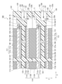
- FIG. 1 is a cross-sectional view showing the structure of a bipolar lead-acid battery according to an embodiment of the present invention.
- FIG. 1 is an enlarged sectional view showing a part of the structure of a bipolar lead-acid battery according to an embodiment of the present invention.
- FIG. 3 is an enlarged cross-sectional view showing a part of another structure of the bipolar lead-acid battery according to the embodiment of the present invention.
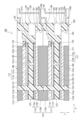
- 1 is an enlarged sectional view showing a part of the structure of a bipolar lead-acid battery according to an embodiment of the present invention with a lid attached; FIG.
- FIG. 1 is a cross-sectional view showing the structure of a bipolar lead-acid battery 100 according to an embodiment of the present invention.
- a bipolar lead-acid battery 100 includes a plurality of cell members 110, a plurality of bipolar plates (space forming members) 120, and a first end plate ( It has a space forming member) 130 and a second end plate (space forming member) 140.
- FIG. 1 shows a bipolar lead-acid battery 100 in which three cell members 110 are stacked
- the number of cell members 110 is determined by the battery design. Further, the number of bipolar plates 120 is determined according to the number of cell members 110.
- the stacking direction of the cell members 110 is assumed to be the Z direction (vertical direction in FIG. 1 or FIG. Let the perpendicular directions be the X direction and the Y direction. Further, the Z direction, which is the stacking direction of the cell members 110, is parallel to the vertical direction.
- the cell member 110 includes a positive electrode 111, a negative electrode 112, and an electrolyte layer (separator) 113.
- the positive electrode 111 includes a positive electrode lead foil 111a, which is a positive electrode current collector made of lead or a lead alloy, and a positive electrode active material layer 111b.
- the negative electrode 112 includes a negative electrode lead foil 112a, which is a negative electrode current collector made of lead or a lead alloy, and a negative electrode active material layer 112b.
- This positive electrode lead foil 111a is bipolarized by an adhesive 150, which will be described later, provided between one surface of the bipolar plate 120 (in the drawing of FIG. 1, the surface facing upward in the paper) and the positive electrode lead foil 111a. It is provided on one side of the plate 120. Therefore, on one surface of the bipolar plate 120, an adhesive layer (adhesive 150), a positive electrode lead foil 111a, and a positive electrode active material layer 111b are laminated in this order.
- the negative electrode lead foil 112a is attached to the bipolar plate by an adhesive 150, which will be described later, provided between the other surface of the bipolar plate 120 (in the drawing of FIG. 1, the surface facing downward in the paper) and the negative electrode lead foil 112a. 120 is provided on the other surface. Therefore, on the other surface of the bipolar plate 120, an adhesive layer (adhesive 150), a negative electrode lead foil 112a, and a negative electrode active material layer 112b are laminated in this order.
- the positive electrode 111 and the negative electrode 112 are electrically connected via a conductor 160, which will be described later.
- the separator 113 is made of, for example, a glass fiber mat impregnated with an electrolytic solution containing sulfuric acid.
- the separator 113 is provided so as to be sandwiched between a positive electrode active material layer 111b provided on one bipolar plate 120 facing each other and a negative electrode active material layer 112b provided on the other bipolar plate 120.
- a positive electrode lead foil 111a, a positive electrode active material layer 111b, a separator 113, a negative electrode active material layer 112b, and a negative electrode lead foil 112a are laminated in this order.
- the bipolar plate 120, the positive electrode lead foil 111a, the positive electrode active material layer 111b, the negative electrode lead foil 112a, and the negative electrode A bipolar electrode is configured by the active material layer 112b.
- a bipolar electrode is an electrode that has the functions of both a positive electrode and a negative electrode.
- the bipolar lead-acid battery 100 is provided in a pair with a cell member 110 having a separator 113 interposed between a positive electrode 111 and a negative electrode 112, with the cell member 110 sandwiched therebetween.
- a plurality of bipolar plates 120 are stacked.
- the dimensions of the positive electrode lead foil 111a in the X and Y directions are larger than the dimensions of the positive electrode active material layer 111b in the X and Y directions.
- the dimensions of the negative electrode lead foil 112a in the X and Y directions are larger than the dimensions of the negative electrode active material layer 112b in the X and Y directions.
- the dimension (thickness) in the Z direction is that the positive electrode lead foil 111a is larger (thicker) than the negative electrode lead foil 112a, and the positive electrode active material layer 111b is larger (thicker) than the negative electrode active material layer 112b. ).
- the plurality of cell members 110 are stacked at intervals in the Z direction, and the substrate 121 of the bipolar plate 120 is disposed at this interval. That is, the plurality of cell members 110 are stacked with the substrate 121 of the bipolar plate 120 sandwiched therebetween.
- the plurality of bipolar plates 120, the first end plate 130, and the second end plate 140 form spaces for forming a plurality of spaces (cells) C that individually accommodate the plurality of cell members 110. It is a member.
- the bipolar plate 120 covers both the positive electrode 111 side and the negative electrode 112 side of the cell member 110, and includes a substrate 121 having a rectangular planar shape, and a frame body that surrounds the side surfaces of the cell member 110 and covers the four end faces of the substrate 121. 122.
- the bipolar plate 120 which is a space forming member, has an outer wall surface 120a and an inner wall surface 120b, and the inner wall surface 120b faces the side surface of the cell member 110.
- a part of the space C that accommodates the cell member 110 is formed by the inner wall surface 120b.
- a part of the outer surface of the bipolar lead-acid battery 100 is formed by the outer wall surface 120a.
- the bipolar plate 120 further includes column parts 123 that protrude perpendicularly from both sides of the substrate 121.
- the number of pillar portions 123 protruding from each surface of the substrate 121 may be one or more.
- the substrate 121, frame body 122, and pillar portion 123 that constitute the bipolar plate 120 are integrally formed of, for example, thermoplastic resin.
- thermoplastic resin forming the bipolar plate 120 include acrylonitrile-butadiene-styrene copolymer (ABS resin) and polypropylene. These thermoplastic resins have excellent moldability and sulfuric acid resistance. Therefore, even if the electrolytic solution comes into contact with the bipolar plate 120, the bipolar plate 120 is unlikely to be decomposed, deteriorated, corroded, or the like.
- the dimensions of the frame 122 are larger than the dimensions (thickness) of the substrate 121, and the dimensions between the protruding end surfaces of the pillars 123 are the same as the dimensions of the frame 122.
- a space C is formed between the substrates 121 by stacking the plurality of bipolar plates 120 with their frame bodies 122 and columnar portions 123 in contact with each other. The dimension of the space C in the Z direction is maintained by the pillar portions 123 that are in contact with each other.
- the positive electrode lead foil 111a, the positive electrode active material layer 111b, the negative electrode lead foil 112a, the negative electrode active material layer 112b, and the separator 113 have through holes 111c, 111d, 112c, 112d, and 113a through which the column parts 123 penetrate. each formed.
- the substrate 121 of the bipolar plate 120 has a plurality of through holes 121a passing through the plate surface.
- a first recess 121b is formed on one surface of the substrate 121, and a second recess 121c is formed on the other surface.
- the depth of the first recess 121b is deeper than the depth of the second recess 121c.
- the dimensions of the first recess 121b and the second recess 121c in the X and Y directions correspond to the dimensions of the positive electrode lead foil 111a and the negative electrode lead foil 112a in the X and Y directions.
- the substrate 121 of the bipolar plate 120 is arranged between adjacent cell members 110 in the Z direction. Then, the positive electrode lead foil 111a of the cell member 110 is placed in the first recess 121b of the substrate 121 of the bipolar plate 120 via an adhesive 150. Further, the negative electrode lead foil 112a of the cell member 110 is placed in the second recess 121c of the substrate 121 of the bipolar plate 120 via an adhesive 150.
- a conductor 160 is arranged in the through hole 121a of the substrate 121 of the bipolar plate 120. Both end surfaces of the conductor 160 are in contact with and bonded to the positive electrode lead foil 111a and the negative electrode lead foil 112a. That is, the conductor 160 electrically connects the positive electrode lead foil 111a and the negative electrode lead foil 112a. As a result, all of the plurality of cell members 110 are electrically connected in series.
- a cover plate 170 is provided at the outer edge of the positive electrode lead foil 111a to cover the outer edge.
- This cover plate 170 is, for example, a thin plate-like frame and has rectangular inner and outer lines.
- the inner edge of the cover plate 170 overlaps with the outer edge of the positive electrode lead foil 111a, and the outer edge of the cover plate 170 overlaps with the peripheral edge of the first recess 121b on one surface of the substrate 121.
- the rectangle that forms the inner line of the cover plate 170 is smaller than the rectangle that forms the outer line of the positive electrode lead foil 111a, and the rectangle that forms the outer line of the cover plate 170 is the rectangle that forms the opening surface of the first recess 121b. bigger.
- the adhesive 150 extends from the end surface of the positive electrode lead foil 111a to the outer edge of the opening side of the first recess 121b, and is disposed between the inner edge of the cover plate 170 and the outer edge of the positive electrode lead foil 111a. Ru. The adhesive 150 is also placed between the outer edge of the cover plate 170 and one surface of the substrate 121.
- the cover plate 170 is fixed by the adhesive 150 across the peripheral edge of the first recess 121b on one surface of the substrate 121 and the outer edge of the positive electrode lead foil 111a. Thereby, the outer edge of the positive electrode lead foil 111a is covered with the cover plate 170 even at the boundary with the peripheral edge of the first recess 121b.
- the outer edge of the negative lead foil 112a may also be covered with a cover plate similar to the cover plate 170 covering the outer edge of the positive lead foil 111a.
- the cover plate has been explained using a thin plate-like frame as an example, it may also be a tape-like material, for example, as long as it is resistant to electrolytes (sulfuric acid). .
- the first end plate 130 is a space forming member that includes a substrate 131 that covers the positive electrode side of the cell member 110 and a frame 132 that surrounds the side surface of the cell member 110. Further, a column portion 133 is provided that projects perpendicularly from one surface of the substrate 131 (the surface of the bipolar plate 120 disposed closest to the positive electrode that faces the substrate 121).
- the first end plate 130 which is a space forming member, has an outer wall surface 130a and an inner wall surface 130b, and the inner wall surface 130b faces the side surface of the cell member 110.
- the planar shape of the substrate 131 is a rectangle, four end faces of the substrate 131 are covered with a frame 132, and the substrate 131, the frame 132, and the pillar portion 133 are integrally formed of, for example, the above-mentioned thermoplastic resin. .
- the number of pillar portions 133 protruding from one surface of the substrate 131 may be one or more. However, the number corresponds to the number of pillars 123 of the bipolar plate 120 that are brought into contact with the pillars 133.
- the dimensions of the frame 132 are larger than the dimensions (thickness) of the substrate 131, and the dimensions between the protruding end surfaces of the pillars 133 are the same as the dimensions of the frame 132.
- the first end plate 130 is stacked with the frame 132 and column 133 in contact with the frame 122 and column 123 of the bipolar plate 120 disposed at the outermost side (on the positive electrode side).
- a space C is formed between the substrate 121 of the bipolar plate 120 and the substrate 131 of the first end plate 130. Furthermore, the dimension of the space C in the Z direction is maintained by the pillar portions 123 of the bipolar plate 120 and the pillar portions 133 of the first end plate 130 that are in contact with each other.
- Through holes 111c, 111d, and 113a are formed in the positive electrode lead foil 111a, the positive electrode active material layer 111b, and the separator 113 of the cell member 110 disposed on the outermost side (positive electrode side), respectively. ing.
- a recess 131b is formed on one surface of the substrate 131 of the first end plate 130.
- the dimensions of the recess 131b in the X and Y directions correspond to the dimensions of the positive electrode lead foil 111a in the X and Y directions.
- the positive electrode lead foil 111a of the cell member 110 is placed in the recess 131b of the substrate 131 of the first end plate 130 with an adhesive 150 interposed therebetween. Further, like the substrate 121 of the bipolar plate 120, a cover plate 170 is fixed to one side of the substrate 131 with an adhesive 150. As a result, the outer edge of the positive electrode lead foil 111a is covered with the cover plate 170 even at the boundary with the peripheral edge of the recess 131b.
- the first end plate 130 includes a positive electrode terminal (not shown in FIG. 1) that is electrically connected to the positive electrode lead foil 111a in the recess 131b.
- the second end plate 140 is a space forming member that includes a substrate 141 that covers the negative electrode side of the cell member 110 and a frame 142 that surrounds the side surface of the cell member 110. Furthermore, a column portion 143 is provided that projects perpendicularly from one surface of the substrate 141 (the surface of the bipolar plate 120 disposed closest to the negative electrode side that faces the substrate 121).
- the second end plate 140 which is a space forming member, has an outer wall surface 140a and an inner wall surface 140b, and the inner wall surface 140b faces the side surface of the cell member 110.
- the planar shape of the substrate 141 is a rectangle, four end faces of the substrate 141 are covered with a frame 142, and the substrate 141, the frame 142, and the pillar portion 143 are integrally formed of, for example, the above-mentioned thermoplastic resin. .
- the number of pillar portions 143 protruding from one surface of the substrate 141 may be one or more. However, the number corresponds to the number of pillars 123 of the bipolar plate 120 that are brought into contact with the pillars 143.
- the dimensions of the frame 142 are larger than the dimensions (thickness) of the substrate 131, and the dimensions between the protruding end surfaces of the two pillars 143 are the same as the dimensions of the frame 142.
- the second end plate 140 is stacked with the frame 142 and column 143 in contact with the frame 122 and column 123 of the bipolar plate 120 disposed at the outermost side (on the negative electrode side).
- a space C is formed between the substrate 121 of the bipolar plate 120 and the substrate 141 of the second end plate 140. Further, the dimension of the space C in the Z direction is maintained by the pillar portions 123 of the bipolar plate 120 and the pillar portions 143 of the second end plate 140 that are in contact with each other.
- Through holes 112c, 112d, and 113a are formed in the negative electrode lead foil 112a, the negative electrode active material layer 112b, and the separator 113 of the cell member 110 disposed on the outermost side (negative electrode side), respectively, through which the pillar portions 143 penetrate. ing.
- a recess 141b is formed on one surface of the substrate 141 of the second end plate 140.
- the dimensions of the recess 141b in the X and Y directions correspond to the dimensions of the negative electrode lead foil 112a in the X and Y directions.
- the negative electrode lead foil 112a of the cell member 110 is placed in the recess 141b of the substrate 141 of the second end plate 140 via an adhesive 150. Further, the second end plate 140 includes a negative electrode terminal (not shown in FIG. 1) that is electrically connected to the negative electrode lead foil 112a in the recess 141b.
- vibration welding when joining the opposing bipolar plates 120, the first end plate 130 and the opposing bipolar plate 120, or the second end plate 140 and the opposing bipolar plate 120, for example, vibration welding ( Various welding methods can be employed, such as vibration welding), ultrasonic welding, and hot plate welding. Among these, vibration welding is a method of welding by vibrating the surfaces to be joined while pressurizing them, and the welding cycle is quick and the reproducibility is good. Therefore, vibration welding is more preferably used.
- the objects to be welded include not only the frames disposed at opposing positions in the mutually opposing bipolar plates 120, first end plate 130, and second end plate 140, but also each column.
- the bipolar lead-acid battery 100 includes a through hole 180 for injecting electrolyte into the space C in which the cell member 110 is accommodated.
- the through hole 180 is formed in one of the four end surfaces of the bipolar plate 120, the first end plate 130, and the second end plate 140.
- FIG. 2 is an enlarged cross-sectional view showing a part of the structure of the bipolar lead-acid battery 100 according to the embodiment of the present invention.
- the cell member 110 sandwiched between two bipolar plates 120, 120 is shown in the center, and the cell member 110 is shown penetrating into the space C formed by the two adjacent bipolar plates 120.
- a through hole 180 is shown.
- the through hole 180 is formed on the right side in FIGS.
- An inner opening 182 that opens to the inner wall surface 120b is provided, and a wall 184 is provided in at least a portion of the through path 183 that connects the outer opening 181 and the inner opening 182.
- the electrolytic solution is injected from the outer opening 181 and into the space C from the inner opening 182 via the through path 183.
- the first end plate 130 includes an outer opening 181 that opens to its outer wall surface 130a and an inner opening 182 that opens to its inner wall surface 130b.
- a through path 183 is formed to connect the two.
- the second end plate 140 also includes an outer opening 181 that opens on the outer wall surface 140a and an inner opening 182 that opens on the inner wall surface 140b, and connects the outer opening 181 and the inner opening 182.
- a through path 183 is formed in this manner.
- the electrolyte When injecting the electrolyte into this space C, the electrolyte is injected with the X direction shown in FIG. 1 being parallel to the vertical direction.
- the bipolar lead-acid battery 100 when the bipolar lead-acid battery 100 is actually used, it is mounted with the Z direction, which is the stacking direction, parallel to the vertical direction, as shown in FIGS. 1 and 2, for example.
- the bipolar lead-acid battery 100 when the battery is placed such that the Z direction is parallel to the vertical direction, the bipolar lead-acid battery 100 is placed so that the positive electrode 111 faces downward in the vertical direction, as shown in FIG.
- the bipolar lead-acid battery 100 when the bipolar lead-acid battery 100 is placed in a direction in which the stacking direction (Z direction) of the cell member 110 and the space forming members 120, 130, 140 is parallel to the vertical direction, the positive electrode 111 is parallel to the negative electrode 112. It is arranged lower in the stacking direction.
- the positive electrode 111 when charging and discharging are performed, a phenomenon occurs in which the positive electrode active material layer 111b softens. When such softening occurs, the bond between the positive electrode lead foil 111a and the positive electrode active material layer 111b becomes weak, and the adhesion between them decreases.
- the electrolytic solution tends to enter between the positive electrode active material layer 111b and the positive electrode lead foil 111a, which may induce peeling of the positive electrode active material layer 111b. Therefore, in order to avoid such a situation, when using the bipolar lead-acid battery 100 and placing it so that the Z direction is parallel to the vertical direction, the positive electrode 111 is placed on the lower side in the vertical direction. Place it so that it looks like this.
- the outer opening 181 of the through hole 180 connects the outer wall surfaces 120a, 130a, 140a (hereinafter referred to as “space forming members”) of the bipolar plate 120, the first end plate 130, and the second end plate 140 (hereinafter referred to as “space forming member”). (hereinafter referred to as the "outer wall surface").
- the outer opening 181 is formed on one side where the positive electrode 111 is provided and the other side where the negative electrode 112 is provided. is formed between the surface of That is, the outer opening 181 includes at least part of the distance between the first recess 121b in the bipolar plate 120 in which the positive electrode lead foil 111a is provided and the second recess 121c in which the negative electrode lead foil 112a is provided. It is formed on the outer wall surface 120a of the substrate 121.
- the outer opening 181 opens in the outer wall surface 120a of the bipolar plate 120 and is formed on an extension of the substrate 121 in the X direction. That is, the outer opening 181 of the through hole 180 is not formed on the extension line of the separator 113 in the X direction, but is formed at a position offset from the extension line.
- the opening distance in the Z direction of the outer opening 181 is the same as that of the first recess 121b, which is shown as the thickness of the bipolar plate 120 in the Z direction. This includes a part of the distance between the second recess 121c and the second recess 121c.
- the inner wall surfaces 120b, 130b, 140b (hereinafter appropriately referred to as "inner wall surfaces") of the space forming member, and the inner opening 182 that penetrates into the space C, are It is not formed on the extension of the separator 113 in the X direction like a hole.
- the opening position of the inner opening 182 is formed so that it is flush with the surface where the negative electrode lead foil 112a and the negative electrode active material layer 112b are in contact with each other in the substrate 121. has been done.
- a wall portion 184 is provided in at least a portion of the through path 183.
- the distance of the wall portion 184 in the Z direction is approximately the same as the distance of the outer opening 181 in the Z direction. Therefore, most of the electrolytic solution injected from the outer opening 181 contacts the wall 184 once, changes its direction by contacting the wall 184, and enters the space C from the inner opening 182.
- the injection hole for injecting the electrolyte has been coaxial and linear in the X direction of the bipolar lead-acid battery 100 from the outer wall surface 120a to the inner wall surface 120b. It was set up to be. In this way, when passing through the space between the outer wall surface 120a and the inner wall surface 120b in the X direction perpendicular to the Z direction, the penetration path 183 becomes the shortest.
- the outer opening 181 and the inner opening 182 of the through hole 180 according to the embodiment of the present invention are arranged in the X direction of the bipolar lead-acid battery 100. They are coaxial with each other and are not arranged in a straight line.
- the wall portion 184 is formed in at least a portion of the through path 183 that connects the outer opening 181 and the inner opening 182.
- the electrolytic solution flowing in from the outer opening 181 flows in the direction of the arrow shown in FIG.
- the flow direction is appropriately referred to as the "first flow direction F1").
- the electrolytic solution contacts the wall portion 184 and flows out from the inner opening 182 into the space C in the direction of the arrow shown in FIG. 2 so as to be parallel to the Z direction (in the following,
- the direction in which such an electrolytic solution flows out from the inner opening 182 into the space C is appropriately referred to as a "second flow direction F2").
- first flow direction F1 and second flow direction F2 are different between the entrance (outer opening 181) and the exit (inner opening 182) of the through path 183. This is because the injected electrolyte comes into contact with the wall portion 184 in the middle of the through path 183. By contacting the wall portion 184, the force of the electrolyte is weakened. Therefore, the force of the electrolyte injected into the space C can be reduced.
- the distance of the wall portion 184 in the Z direction is approximately the same as the distance of the outer opening 181 in the Z direction, as described above.
- the opening position of the inner opening 182 is formed to be flush with the surface of the substrate 121 where the negative electrode lead foil 112a and the negative electrode active material layer 112b are in contact. Therefore, when viewed from the outer opening 181 in parallel to the X direction, the wall 184 is visible from the outer opening 181 in front in the X direction, and the inner opening 182 is not visible.
- FIG. 3 is an enlarged cross-sectional view showing a part of another structure of the bipolar lead-acid battery 100A according to the embodiment of the present invention.
- the distance in the Z direction of the wall portion 184 is shorter than the distance in the Z direction of the outer opening 181A. That is, when viewed parallel to the X direction from the outer opening 181A, not only the wall 184A can be seen from the outer opening 181A in front in the X direction, but the inner opening 182A can also be seen, and a part of the space C can also be seen. I can see it.
- a wall portion 184A is provided in at least a portion thereof. Therefore, not all of the electrolytic solution flowing in the first flow direction F1 from the outer opening 181A contacts the wall portion 184, but a portion thereof contacts the wall portion 184A. Then, it changes its direction to the second flow direction F2, and mixes with the electrolytic solution that does not contact the wall portion 184A.
- the electrolytic solution flowing from the outer opening 181A loses its momentum by contacting the wall 184A, and the electrolytic solution whose flow direction has changed from the first flow direction F1 to the second flow direction F2.
- the liquid is separated into the electrolytic solution and the electrolytic solution, which does not come into contact with the wall portion 184A and maintains the same force as when it was injected.
- both of them mix when flowing into the space C, the force of the electrolytic solution flowing into the space C can be weakened as a result.
- a wall portion 184 is provided in a clear shape.
- the force of the electrolyte flowing into the space C can be weakened by, for example, providing the through path 183 so as not to be parallel to the direction of injection of the electrolyte. be able to.
- the electrolyte when the electrolyte is injected into the space C, it is injected in a direction parallel to the X direction.
- the electrolytic solution flowing from the outer opening 181 may flow into any part of the inner wall surface of the through path 183. (wall portion 184). Therefore, at least a portion of the injected electrolyte can have its inflow direction (first flow direction F1) and outflow direction (second flow direction F2) different. Therefore, it is possible to reduce the force of the electrolytic solution during injection, and the possibility that the electrolytic solution comes into direct contact with the separator 113 can be reduced.
- the through hole 180 is formed so that the electrolyte injected in this way cannot directly enter the space C from the outer opening 181, the components of the cell member 110 are not deformed by the pressure when the electrolyte is injected. or damage can be avoided. As a result, it is possible to prevent a short circuit from occurring between the positive electrode side and the negative electrode side inside the cell member 110, and to prevent the performance of the bipolar lead-acid battery 100 from deteriorating.
- the opening of the through-hole 180 is not located on the line in the X direction of the separator 113, so that the space C Even if the electrolytic solution is injected into the separator 113, the electrolytic solution can be prevented from directly contacting the separator 113. Further, even if the electrolytic solution comes into direct contact with the separator 113, it is possible to prevent the electrolytic solution from coming into contact with the separator 113 forcefully. Therefore, pressure due to injection of the electrolyte is not applied to the separator 113 or is reduced, so that the separator 113 is not deformed.
- the length of the frame in the Z direction that is, the thickness when the bipolar lead-acid battery 100 is placed in the stacking direction, is The thickness must be such that it can be formed. This leads to an increase in the thickness of the frame, resulting in an increase in the size of the bipolar lead-acid battery 100 in the Z direction.
- the outer opening 181 is located on the outer wall surface of the bipolar plate 120 on the extension line of the substrate 121 in the X direction. 120a. This makes it possible to utilize the area of the bipolar plate 120 on the extension line of the substrate 121 in the X direction, which has been a so-called dead space so far.
- the bipolar lead-acid battery 100 in the Z direction can be made more compact and space-saving.
- the outer opening 181 is formed on the outer wall surface 120a of the bipolar plate 120 on the extension line of the substrate 121 in the X direction, it is also possible to widen the opening in the Z direction. Therefore, the outer opening 181 having a larger opening than the conventional liquid injection hole can be formed, and the electrolytic solution can be injected into the space C more smoothly.
- the inner opening 182 is the inner wall surface of the space forming member and opens toward the space C as before. Therefore, not only can the electrolytic solution be injected as before, but also the opening surface is not on the line in the X direction of the separator 113, so the above-mentioned disadvantages caused by the electrolytic solution injection can be avoided.
- the through hole 180 in the embodiment of the present invention is formed in such a shape, the injected electrolyte does not directly contact the components of the cell member 110, or the force of the electrolyte intrusion is suppressed. It does not necessarily have to have this shape as long as it has a weakening structure.
- the direction of the electrolyte when it is injected from the outer opening 181 and the direction of the electrolyte that enters the space C from the inner opening 182 are The directions do not need to be different.
- the outer opening 181 and the inner opening 182 are arranged so that the electrolyte entering from the inner opening 182 does not come into direct contact with the components.
- the opening surface of the inner opening 181 and the opening surface of the inner opening 182 can be arranged to be offset from each other.
- the electrolytic solution when the electrolytic solution is injected into the space C, for example, a component other than the separator 113 disposed in the space C, such as the cover plate 170, which is stronger than the separator 113, It is also possible to adopt a structure that allows the electrolyte to be injected in contact with it.
- the structure of the through-hole 180 may be such that it penetrates from the outer opening 181 to the inner opening 182. Therefore, for example, the through path 183 may be formed in a U-shaped tube shape or a spiral shape, or the structure may be such that the electrolytic solution can be injected into the space C intermittently. Alternatively, the penetration path 183 may be bent or curved in the middle.
- the inner opening 182 of the through hole 180 is formed on one surface or the other surface of the substrate 121. In the embodiment of the present invention, the inner opening 182 is formed flush with the bonding surface between the negative electrode lead foil 112a and the negative electrode active material 112b. Similarly, the lower end of the opening surface of the outer opening 181 of the through hole 180 in the Z direction is flush with the bonding surface of the inner opening 182 between the negative electrode lead foil 112a and the negative electrode active material 112b.
- the lower end in the Z direction of the opening surface of the outer opening 181 of the through hole 180 is flush with the bonding surface between the negative electrode lead foil 112a and the negative electrode active material 112b, where the inner opening 182 is formed.
- the lower end (opening position of the outer opening 181) is, for example, above the opening position of the inner opening 182 in the direction in which the stacking direction of the cell member 110 and the space forming member 120 is parallel to the vertical direction. It is also possible to provide the That is, it is placed higher in the stacking direction, such as at a position flush with the second recess 121c in the substrate 121 of the bipolar plate 120. This can further reduce the possibility that the electrolyte will leak to the outside through the through hole 180.
- the opening position of the inner opening 182 in the embodiment of the present invention is formed so as to be flush with the surface of the substrate 121 where the negative electrode lead foil 112a and the negative electrode active material layer 112b are in contact with each other. ing. However, it does not necessarily have to be formed in this way. That is, for example, it is also possible to form it above the surface of the substrate 121 where the negative electrode lead foil 112a and the negative electrode active material layer 112b are in contact with each other in the stacking direction.
- the shapes of the outer opening 181 and the inner opening 182 may be, for example, circular or oval. I can do it. Further, the diameter of these openings can be, for example, 1 mm to 5 mm.
- the bipolar lead-acid battery 100 of this embodiment can be manufactured, for example, by a method including the steps described below.
- the substrate 121 of the bipolar plate 120 is placed on a workbench with the first recess 121b side facing upward. Then, adhesive 150 is applied to the first recess 121b, and the positive electrode lead foil 111a is placed in the first recess 121b. At that time, the pillar portion 123 of the bipolar plate 120 is passed through the through hole 111c of the positive electrode lead foil 111a. This adhesive 150 is cured, and a positive electrode lead foil 111a is attached to one surface of the substrate 121.
- the adhesive 150 is applied to the outer edge of the positive electrode lead foil 111a and the upper surface of the substrate 121 which becomes the edge of the first recess 121b, and the cover plate 170 is placed thereon, and the adhesive 150 is cured. Thereby, the cover plate 170 is fixed over the outer edge of the positive electrode lead foil 111a and over the portion of the substrate 121 (the periphery of the first recess 121b) that continues to the outside thereof.
- bipolar plate 120 with lead foil for positive and negative electrodes is obtained.
- a necessary number of bipolar plates 120 with lead foil for positive and negative electrodes are prepared.
- adhesive 150 is applied on the outer edge of the positive electrode lead foil 111a and on the upper surface of the substrate 131 that will become the edge of the recess 131b.
- a cover plate 170 is placed on top of this adhesive 150, and the adhesive 150 is cured. Thereby, the cover plate 170 is fixed over the outer edge of the positive electrode lead foil 111a and over the portion of the substrate 131 that continues outside of the outer edge. Thereby, an end plate with lead foil for the positive electrode is obtained.
- the first end plate 130 to which the positive electrode lead foil 111a and the cover plate 170 are fixed is placed on a workbench with the positive electrode lead foil 111a facing upward.
- the positive electrode active material layer 111b is placed in the cover plate 170 and placed on the positive electrode lead foil 111a.
- the column portion 133 of the first end plate 130 is passed through the through hole 111d of the positive electrode active material layer 111b.
- the separator 113 and the negative electrode active material layer 112b are placed on the positive electrode active material layer 111b.
- the bipolar plate 120 with lead foil for positive and negative electrodes is placed on the first end plate 130 in this state with the lead foil 112a side for negative electrode facing downward.
- the pillars 123 of the bipolar plate 120 are passed through the through holes 113a of the separator 113 and the through holes 112d of the negative electrode active material layer 112b, and placed on the pillars 133 of the first end plate 130.
- the frame 122 of the bipolar plate 120 is placed on the frame 132 of the first end plate 130.
- the first end plate 130 is fixed and vibration welding is performed while the bipolar plate 120 is vibrated in the diagonal direction of the substrate 121.
- the frame 122 of the bipolar plate 120 is joined onto the frame 132 of the first end plate 130.
- the column portion 123 of the bipolar plate 120 is joined onto the column portion 133 of the first end plate 130 .
- the bipolar plate 120 is joined onto the first end plate 130.
- the cell member 110 is placed in the space C formed by the first end plate 130 and the bipolar plate 120, and the positive electrode lead foil 111a is exposed on the upper surface of the bipolar plate 120.
- the positive electrode active material layer 111b, the separator 113, and the negative electrode active material layer are placed on the thus obtained composite body in which the bipolar plate 120 is joined onto the first end plate 130. 112b are placed in this order. Thereafter, another bipolar plate 120 with lead foil for positive and negative electrodes is placed with the lead foil 112a side for negative electrodes facing downward.
- this combined body is fixed, and vibration welding is performed while vibrating another bipolar plate 120 with lead foil for positive and negative electrodes in the diagonal direction of the substrate 121. This vibration welding process is continued until the required number of bipolar plates 120 are joined onto the first end plate 130.
- the positive electrode active material layer 111b, the separator 113, and the negative electrode active material layer 112b are placed in this order on the uppermost bipolar plate 120 of the combined body in which all the bipolar plates 120 are joined. Thereafter, the second end plate 140 is further placed with the negative electrode lead foil 112a side facing down.
- the combined body is fixed and vibration welding is performed while vibrating the second end plate 140 in the diagonal direction of the substrate 141.
- the second end plate 140 is joined onto the uppermost bipolar plate 120 of the combined body in which all the bipolar plates 120 are joined.
- a joining structure is formed by vibration welding the opposing surfaces of the frames.
- a through hole 180 is formed in the space forming member so that an inner opening 182 is formed at the position of each space C on one end surface of the bipolar lead-acid battery 100 in the X direction, for example.
- a predetermined amount of electrolyte is injected into each space C through the through-hole 180, and the separator 113 is impregnated with the electrolyte. Then, the bipolar lead-acid battery 100 can be manufactured by chemically forming it under predetermined conditions.
- FIG. 4 is an enlarged cross-sectional view showing a part of the structure of the bipolar lead-acid battery 100 according to the embodiment of the present invention with a lid 190 attached. Note that, in FIG. 4, of the structure of the lid 190, only the structure necessary for injecting the electrolyte into the space C is extracted and drawn. Therefore, other structures included in the lid 190 are omitted from drawing.
- a communication port 191 is provided in the lid 190.
- This communication port 191 plays the role of a through port used for injecting the electrolyte into the space C. That is, after the lid 190 is attached to the bipolar lead-acid battery 100, the electrolytic solution is injected into the space C from the communication port 191 through the through hole 180.
- the communication port 191 After the necessary amount is injected, the communication port 191 is sealed. Therefore, after manufacturing, the liquid injection port 191 serves as an exhaust port for exhausting gas generated in the space C in which the cell member 110 is accommodated.
- the shape of the opening of the communication port 191 can be, for example, circular or oval. Further, the diameter of these openings can be, for example, 4 mm to 10 mm.
- the arrangement position of such communication port 191 is as described below. That is, as described above, when the bipolar lead acid battery 100 is used, it is placed so that the Z direction, which is the stacking direction, is parallel to the vertical direction. When the bipolar lead-acid battery 100 is placed in this manner, the communication port 191 is formed to be located above the position of the outer opening 181 of the through hole 180 in the Z direction.
- the communication port 191 is arranged at a higher position in the Z direction than the through hole 180. become. Therefore, even if the electrolytic solution leaks from the through hole 180, it is possible to prevent the electrolyte from leaking to the outside from the lid 190.
- the relationship between the through hole 180 and the communication port 191 of the lid 190 is set as follows, for example.
- the cross-sectional area of the through-hole 180 in a cross section perpendicular to the injection direction of the electrolytic solution is defined as a first opening area a1. Therefore, for example, when a plurality of through holes 180 are provided, the total opening area of the through holes 180 is "the number of the plurality of through holes 180 x a1".
- the cross-sectional area of one communication port 191 provided in the lid 190 in a cross section perpendicular to the injection direction of the electrolytic solution is defined as a second opening area a2.
- the value understood as the "cross-sectional area" for both the first opening area a1 and the second opening area a2 is the value at which the cross-sectional area of the through-hole 180 and the communication opening 191 is the smallest.
- the relationship between the first opening area a1 and the second opening area a2 is "the number of the plurality of through holes 180 x a1 ⁇ a2". That is, the total opening area of the first opening area a1 of the through-hole 180 is greater than or equal to the second opening area a2 of the communication opening 191.
- the total opening area of the first opening area a1 is 1.5 times or more and 4 times or less of the second opening area a2.
- the first opening area a1 which is the cross-sectional area of each through-hole 180, is 0.5 times or more and less than 4 times the second opening area a2.
- the space C can be The opening can be made larger.
- the electrolyte when the electrolyte is injected into the space C of the bipolar lead-acid battery 100 from the communication port 191, the electrolyte is dispersed into each through-hole 180, so that the force of the electrolyte can be weakened. Therefore, the influence on the cell member 110 due to the pressure of the electrolytic solution during injection can be minimized. Further, since the electrolytic solution is injected into the space C through one of the through holes 180, it is possible to avoid prolonging the time required for injection.
- a space forming member including; a through hole penetrating into the space in which the cell member is accommodated; has The through hole includes an outer opening that opens to an outer wall surface of the space forming member, and an inner opening that opens to an inner wall surface of the space forming member, At least a portion of the through path connecting the outer opening and the inner opening has a first flow direction of the electrolytic solution flowing from the outer opening and a direction in which the electrolytic solution flows from the inner opening into the space.
- a bipolar storage battery characterized by having a wall portion having a direction different from a second flow direction in which the flow flows out.
- the outer opening is formed in an outer wall surface of the substrate that includes at least a part of the distance between one surface where the positive electrode is provided and the other surface where the negative electrode is provided.
- (4) The inner opening is provided at a position where the electrolytic solution does not come into direct contact with the separator when the electrolytic solution is injected into the space (1) to (3) above.
- the bipolar storage battery according to any one of (1) to (4) above, wherein the bipolar storage battery is provided above the position in the stacking direction.
- the bipolar storage battery further includes a lid that covers a portion of the frame that surrounds one side of the cell member, The lid has a communication port that communicates with the through-hole, When the bipolar storage battery is placed such that the stacking direction of the cell member and the space forming member is parallel to the vertical direction, the opening position of the communication port is the opening position of the outer opening of the through hole.
- a space forming member including; a through hole penetrating into the space in which the cell member is accommodated; has The through hole includes an outer opening that opens to an outer wall surface of the space forming member, and an inner opening that opens to an inner wall surface of the space forming member, The opening position of the outer opening is located above the opening position of the inner opening in a direction in which the stacking direction of the cell member and the space forming member is parallel to the vertical direction.
- a bipolar storage battery (9) The bipolar storage battery according to any one of (1) to (8) above, wherein the positive electrode current collector and the negative electrode current collector are made of lead or a lead alloy.
- Substrate of second end plate 142 Frame of second end plate 150... Adhesive 160... Conductor 170... Cover plate 180... Penetration port 181... Outer opening 182... Inner opening 183... Penetration route 184... Wall portion 190... Lid 191 ...Communication port C...Cell (space that accommodates cell members) F1...First flow direction (of electrolyte) F2...Second flow direction (of electrolyte)
Landscapes
- Chemical & Material Sciences (AREA)
- Chemical Kinetics & Catalysis (AREA)
- Electrochemistry (AREA)
- General Chemical & Material Sciences (AREA)
- Engineering & Computer Science (AREA)
- Manufacturing & Machinery (AREA)
- Secondary Cells (AREA)
Abstract
Description
まず、本発明の実施の形態における双極型鉛蓄電池の全体構成について説明する。図1は、本発明の実施の形態に係る双極型鉛蓄電池100の構造を示す断面図である。
この実施の形態の双極型鉛蓄電池100は、例えば、以下に説明する各工程を有する方法で製造することができる。
先ず、バイポーラプレート120の基板121を、第1の凹部121b側を上に向けて作業台に置く。そして第1の凹部121bに接着剤150を塗布し、第1の凹部121b内に正極用鉛箔111aを入れる。その際に、正極用鉛箔111aの貫通穴111cにバイポーラプレート120の柱部123を通す。この接着剤150を硬化させて、基板121の一面に正極用鉛箔111aを貼り付ける。
第1のエンドプレート130の基板131を、凹部131b側を上に向けて作業台に置く。そして凹部131bに接着剤150を塗布し、凹部131b内に正極用鉛箔111aを入れて接着剤150を硬化させる。その際に、正極用鉛箔111aの貫通穴111cにエンドプレート130の柱部133を通す。この接着剤150を硬化させて、基板131の一面に正極用鉛箔111aを貼り付ける。
第2のエンドプレート140の基板141を、凹部141b側を上に向けて作業台に置く。そして凹部141bに接着剤150を塗布し、凹部141b内に負極用鉛箔112aを入れて接着剤150を硬化させる。その際に、負極用鉛箔112aの貫通穴112cに第2のエンドプレート140の柱部143を通す。この接着剤150を硬化させて、基板141の一面に負極用鉛箔112aが貼り付けられた第2のエンドプレート140を得る。
先ず、正極用鉛箔111aおよびカバープレート170が固定された第1のエンドプレート130を、正極用鉛箔111aを上に向けて作業台に置く。そしてカバープレート170の中に正極用活物質層111bを入れて正極用鉛箔111aの上に置く。その際に、正極用活物質層111bの貫通穴111dに第1のエンドプレート130の柱部133を通す。次に、正極用活物質層111bの上に、セパレータ113、負極用活物質層112bを置く。
上述の各プレート同士の積層、接合工程において、枠体の対向面同士の振動溶接による接合構造が形成される。双極型鉛蓄電池100の例えばX方向の一端面の各空間Cの位置に内側開口部182が形成されるように、空間形成部材には貫通口180が形成されている。この貫通口180から各空間Cの内部に電解液を所定量注液し、セパレータ113に電解液を含浸させる。その上で所定の条件で化成することで、双極型鉛蓄電池100を作製できる。
(1)正極用集電体と正極用活物質層を有する正極、負極用集電体と負極用活物質層を有する負極、および前記正極と前記負極との間に介在するセパレータを備え、間隔を開けて積層配置された、セル部材と、
複数の前記セル部材を個別に収容する複数の空間を形成する、前記セル部材の前記正極の側および前記負極の側の少なくとも一方を覆う基板と、前記セル部材の側面を囲う枠体と、を含む空間形成部材と、
前記セル部材が収容される前記空間内に貫通する貫通口と、
を有し、
前記貫通口は、前記空間形成部材の外壁面に開口する外側開口部と、前記空間形成部材の内壁面に開口する内側開口部とを備え、
前記外側開口部と前記内側開口部とをつなぐ貫通経路の少なくとも一部には、前記外側開口部から流入する電解液の第1の流れ方向と、前記電解液が前記内側開口部から前記空間内に流出する第2の流れ方向とを異なる方向とする壁部を有することを特徴とする双極型蓄電池。
(2)前記外側開口部は、前記正極が設けられる一方の面と前記負極が設けられる他方の面との間の距離の少なくとも一部を含む前記基板の外壁面に形成されていることを特徴とする上記(1)に記載の双極型蓄電池。
(3)前記内側開口部は、前記基板の前記一方の面あるいは前記他方の面に形成されていることを特徴とする上記(1)または(2)に記載の双極型蓄電池。
(4)前記内側開口部は、前記空間内に電解液が注入される際に、前記電解液が前記セパレータに直接接触しない位置に設けられていることを特徴とする上記(1)ないし(3)のいずれかに記載の双極型蓄電池。
(5)前記セル部材と前記空間形成部材との積層方向が鉛直方向と平行となるように前記双極型蓄電池を載置した場合に、前記外側開口部の開口位置が、前記内側開口部の開口位置よりも前記積層方向上方に設けられていることを特徴とする上記(1)ないし(4)のいずれかに記載の双極型蓄電池。
(6)前記双極型蓄電池は、さらに、前記枠体の前記セル部材の1つの側面を囲う部分を覆う蓋を備え、
前記蓋は、前記貫通口と連通する連通口を有し、
前記セル部材と前記空間形成部材との積層方向が鉛直方向と平行となるように前記双極型蓄電池を載置した場合に、前記連通口の開口位置が、前記貫通口の前記外側開口部の開口位置よりも前記積層方向上方に設けられていることを特徴とする上記(1)ないし(5)のいずれかに記載の双極型蓄電池。
(7)前記セル部材と前記空間形成部材との積層方向が鉛直方向と平行となるように前記双極型蓄電池を載置した場合に、前記正極は前記負極よりも前記積層方向下方に配置されることを特徴とする上記(1)ないし(6)のいずれかに記載の双極型蓄電池。
(8)正極用集電体と正極用活物質層を有する正極、負極用集電体と負極用活物質層を有する負極、および前記正極と前記負極との間に介在するセパレータを備え、間隔を開けて積層配置された、セル部材と、
複数の前記セル部材を個別に収容する複数の空間を形成する、前記セル部材の前記正極の側および前記負極の側の少なくとも一方を覆う基板と、前記セル部材の側面を囲う枠体と、を含む空間形成部材と、
前記セル部材が収容される前記空間内に貫通する貫通口と、
を有し、
前記貫通口は、前記空間形成部材の外壁面に開口する外側開口部と、前記空間形成部材の内壁面に開口する内側開口部とを備え、
前記外側開口部の開口位置は、前記セル部材と前記空間形成部材との積層方向が鉛直方向と平行となる方向において、前記内側開口部の開口位置よりも上方に設けられていることを特徴とする双極型蓄電池。
(9)前記正極用集電体及び前記負極用集電体は、鉛又は鉛合金からなることを特徴とする上記(1)ないし(8)のいずれかに記載の双極型蓄電池。
110・・・セル部材
111・・・正極
112・・・負極
111a・・・正極用鉛箔
112a・・・負極用鉛箔
111b・・・正極用活物質層
112b・・・負極用活物質層
113・・・セパレータ
120・・・バイポーラプレート
120a・・・外壁面
120b・・・内壁面
121・・・バイポーラプレートの基板
121a・・・基板の貫通穴
122・・・バイポーラプレートの枠体
130・・・第1のエンドプレート
130a・・・外壁面
130b・・・内壁面
131・・・第1のエンドプレートの基板
132・・・第1のエンドプレートの枠体
140・・・第2のエンドプレート
140a・・・外壁面
140b・・・内壁面
141・・・第2のエンドプレートの基板
142・・・第2のエンドプレートの枠体
150・・・接着剤
160・・・導通体
170・・・カバープレート
180・・・貫通口
181・・・外側開口部
182・・・内側開口部
183・・・貫通経路
184・・・壁部
190・・・蓋
191・・・連通口
C・・・セル(セル部材を収容する空間)
F1・・・(電解液の)第1の流れ方向
F2・・・(電解液の)第2の流れ方向
Claims (9)
- 正極用集電体と正極用活物質層を有する正極、負極用集電体と負極用活物質層を有する負極、および前記正極と前記負極との間に介在するセパレータを備え、間隔を開けて積層配置された、セル部材と、
複数の前記セル部材を個別に収容する複数の空間を形成する、前記セル部材の前記正極の側および前記負極の側の少なくとも一方を覆う基板と、前記セル部材の側面を囲う枠体と、を含む空間形成部材と、
前記セル部材が収容される前記空間内に貫通する貫通口と、
を有し、
前記貫通口は、前記空間形成部材の外壁面に開口する外側開口部と、前記空間形成部材の内壁面に開口する内側開口部とを備え、
前記外側開口部と前記内側開口部とをつなぐ貫通経路の少なくとも一部には、前記外側開口部から流入する電解液の第1の流れ方向と、前記電解液が前記内側開口部から前記空間内に流出する第2の流れ方向とを異なる方向とする壁部を有することを特徴とする双極型蓄電池。 - 前記外側開口部は、前記正極が設けられる一方の面と前記負極が設けられる他方の面との間の距離の少なくとも一部を含む前記基板の外壁面に形成されていることを特徴とする請求項1に記載の双極型蓄電池。
- 前記内側開口部は、前記基板の前記一方の面あるいは前記他方の面に形成されていることを特徴とする請求項1に記載の双極型蓄電池。
- 前記内側開口部は、前記空間内に電解液が注入される際に、前記電解液が前記セパレータに直接接触しない位置に設けられていることを特徴とする請求項1に記載の双極型蓄電池。
- 前記セル部材と前記空間形成部材との積層方向が鉛直方向と平行となるように前記双極型蓄電池を載置した場合に、前記外側開口部の開口位置が、前記内側開口部の開口位置よりも前記積層方向上方に設けられていることを特徴とする請求項1に記載の双極型蓄電池。
- 前記双極型蓄電池は、さらに、前記枠体の前記セル部材の1つの側面を囲う部分を覆う蓋を備え、
前記蓋は、前記貫通口と連通する連通口を有し、
前記セル部材と前記空間形成部材との積層方向が鉛直方向と平行となるように前記双極型蓄電池を載置した場合に、前記連通口の開口位置が、前記貫通口の前記外側開口部の開口位置よりも前記積層方向上方に設けられていることを特徴とする請求項1に記載の双極型蓄電池。 - 前記セル部材と前記空間形成部材との積層方向が鉛直方向と平行となるように前記双極型蓄電池を載置した場合に、前記正極は前記負極よりも前記積層方向下方に配置されることを特徴とする請求項1に記載の双極型蓄電池。
- 正極用集電体と正極用活物質層を有する正極、負極用集電体と負極用活物質層を有する負極、および前記正極と前記負極との間に介在するセパレータを備え、間隔を開けて積層配置された、セル部材と、
複数の前記セル部材を個別に収容する複数の空間を形成する、前記セル部材の前記正極の側および前記負極の側の少なくとも一方を覆う基板と、前記セル部材の側面を囲う枠体と、を含む空間形成部材と、
前記セル部材が収容される前記空間内に貫通する貫通口と、
を有し、
前記貫通口は、前記空間形成部材の外壁面に開口する外側開口部と、前記空間形成部材の内壁面に開口する内側開口部とを備え、
前記外側開口部の開口位置は、前記セル部材と前記空間形成部材との積層方向が鉛直方向と平行となる方向において、前記内側開口部の開口位置よりも上方に設けられていることを特徴とする双極型蓄電池。 - 前記正極用集電体及び前記負極用集電体は、鉛又は鉛合金からなることを特徴とする請求項1ないし請求項8のいずれかに記載の双極型蓄電池。
Priority Applications (2)
| Application Number | Priority Date | Filing Date | Title |
|---|---|---|---|
| JP2024509880A JPWO2023181795A1 (ja) | 2022-03-24 | 2023-02-27 | |
| US18/893,216 US20250015471A1 (en) | 2022-03-24 | 2024-09-23 | Bipolar Storage Battery |
Applications Claiming Priority (2)
| Application Number | Priority Date | Filing Date | Title |
|---|---|---|---|
| JP2022-048863 | 2022-03-24 | ||
| JP2022048863 | 2022-03-24 |
Related Child Applications (1)
| Application Number | Title | Priority Date | Filing Date |
|---|---|---|---|
| US18/893,216 Continuation US20250015471A1 (en) | 2022-03-24 | 2024-09-23 | Bipolar Storage Battery |
Publications (1)
| Publication Number | Publication Date |
|---|---|
| WO2023181795A1 true WO2023181795A1 (ja) | 2023-09-28 |
Family
ID=88100546
Family Applications (1)
| Application Number | Title | Priority Date | Filing Date |
|---|---|---|---|
| PCT/JP2023/007096 Ceased WO2023181795A1 (ja) | 2022-03-24 | 2023-02-27 | 双極型蓄電池 |
Country Status (3)
| Country | Link |
|---|---|
| US (1) | US20250015471A1 (ja) |
| JP (1) | JPWO2023181795A1 (ja) |
| WO (1) | WO2023181795A1 (ja) |
Citations (3)
| Publication number | Priority date | Publication date | Assignee | Title |
|---|---|---|---|---|
| JP2002270218A (ja) * | 2001-03-12 | 2002-09-20 | Shin Kobe Electric Mach Co Ltd | 小形制御弁式鉛蓄電池及びその製造方法 |
| JP2018106850A (ja) * | 2016-12-22 | 2018-07-05 | 株式会社豊田自動織機 | 注液装置及び注液方法 |
| JP2022030155A (ja) * | 2020-08-06 | 2022-02-18 | 株式会社豊田自動織機 | 蓄電装置 |
-
2023
- 2023-02-27 JP JP2024509880A patent/JPWO2023181795A1/ja active Pending
- 2023-02-27 WO PCT/JP2023/007096 patent/WO2023181795A1/ja not_active Ceased
-
2024
- 2024-09-23 US US18/893,216 patent/US20250015471A1/en active Pending
Patent Citations (3)
| Publication number | Priority date | Publication date | Assignee | Title |
|---|---|---|---|---|
| JP2002270218A (ja) * | 2001-03-12 | 2002-09-20 | Shin Kobe Electric Mach Co Ltd | 小形制御弁式鉛蓄電池及びその製造方法 |
| JP2018106850A (ja) * | 2016-12-22 | 2018-07-05 | 株式会社豊田自動織機 | 注液装置及び注液方法 |
| JP2022030155A (ja) * | 2020-08-06 | 2022-02-18 | 株式会社豊田自動織機 | 蓄電装置 |
Also Published As
| Publication number | Publication date |
|---|---|
| US20250015471A1 (en) | 2025-01-09 |
| JPWO2023181795A1 (ja) | 2023-09-28 |
Similar Documents
| Publication | Publication Date | Title |
|---|---|---|
| KR101735511B1 (ko) | 패턴화된 형상을 갖는 배터리 셀 및 그 제조방법 | |
| JP2011165589A (ja) | 燃料電池 | |
| US20230361312A1 (en) | Bipolar Storage Battery | |
| JP2007188693A (ja) | 燃料電池および燃料電池の製造方法 | |
| WO2023181796A1 (ja) | 双極型蓄電池 | |
| US20250015471A1 (en) | Bipolar Storage Battery | |
| JP2022112924A (ja) | 双極型鉛蓄電池 | |
| WO2023189094A1 (ja) | 双極型蓄電池 | |
| WO2024004764A1 (ja) | 双極型蓄電池 | |
| WO2023085068A1 (ja) | 双極型蓄電池 | |
| JP2023076861A (ja) | 双極型蓄電池 | |
| JP7724279B2 (ja) | 双極型蓄電池 | |
| KR100388908B1 (ko) | 리튬 2차 전지 | |
| JP2025011536A (ja) | 双極型蓄電池 | |
| WO2022215349A1 (ja) | バイポーラ型蓄電池、及びその製造方法 | |
| JP2025150833A (ja) | 双極型蓄電池用バイプレート、双極型蓄電池 | |
| JP2022122593A (ja) | バイポーラ電極、バイポーラ型鉛蓄電池、及びその製造方法 | |
| JP2025149461A (ja) | 双極型蓄電池用バイプレート、双極型蓄電池 | |
| JP2023024096A (ja) | 双極型蓄電池 | |
| JP2025116681A (ja) | 双極型鉛蓄電池 | |
| JP7458559B2 (ja) | 双極型蓄電池及び双極型蓄電池の製造方法 | |
| WO2024029366A1 (ja) | 双極型蓄電池 | |
| JP2025163828A (ja) | 双極型蓄電池 | |
| JP2025150816A (ja) | 双極型蓄電池及び双極型蓄電池の製造方法 | |
| JP2023001638A (ja) | 双極型蓄電池 |
Legal Events
| Date | Code | Title | Description |
|---|---|---|---|
| 121 | Ep: the epo has been informed by wipo that ep was designated in this application |
Ref document number: 23774394 Country of ref document: EP Kind code of ref document: A1 |
|
| ENP | Entry into the national phase |
Ref document number: 2024509880 Country of ref document: JP Kind code of ref document: A |
|
| WWE | Wipo information: entry into national phase |
Ref document number: 2401006121 Country of ref document: TH |
|
| WWE | Wipo information: entry into national phase |
Ref document number: 202417075928 Country of ref document: IN |
|
| NENP | Non-entry into the national phase |
Ref country code: DE |
|
| 122 | Ep: pct application non-entry in european phase |
Ref document number: 23774394 Country of ref document: EP Kind code of ref document: A1 |