WO2023181568A1 - コントローラ及びコンピュータ - Google Patents
コントローラ及びコンピュータ Download PDFInfo
- Publication number
- WO2023181568A1 WO2023181568A1 PCT/JP2022/047895 JP2022047895W WO2023181568A1 WO 2023181568 A1 WO2023181568 A1 WO 2023181568A1 JP 2022047895 W JP2022047895 W JP 2022047895W WO 2023181568 A1 WO2023181568 A1 WO 2023181568A1
- Authority
- WO
- WIPO (PCT)
- Prior art keywords
- controller
- marker
- housing
- casing
- image
- Prior art date
- Legal status (The legal status is an assumption and is not a legal conclusion. Google has not performed a legal analysis and makes no representation as to the accuracy of the status listed.)
- Ceased
Links
Images


Classifications
-
- G—PHYSICS
- G06—COMPUTING OR CALCULATING; COUNTING
- G06F—ELECTRIC DIGITAL DATA PROCESSING
- G06F3/00—Input arrangements for transferring data to be processed into a form capable of being handled by the computer; Output arrangements for transferring data from processing unit to output unit, e.g. interface arrangements
- G06F3/01—Input arrangements or combined input and output arrangements for interaction between user and computer
- G06F3/03—Arrangements for converting the position or the displacement of a member into a coded form
- G06F3/033—Pointing devices displaced or positioned by the user, e.g. mice, trackballs, pens or joysticks; Accessories therefor
- G06F3/0346—Pointing devices displaced or positioned by the user, e.g. mice, trackballs, pens or joysticks; Accessories therefor with detection of the device orientation or free movement in a three-dimensional [3D] space, e.g. 3D mice, 6-DOF [six degrees of freedom] pointers using gyroscopes, accelerometers or tilt-sensors
-
- G—PHYSICS
- G06—COMPUTING OR CALCULATING; COUNTING
- G06F—ELECTRIC DIGITAL DATA PROCESSING
- G06F3/00—Input arrangements for transferring data to be processed into a form capable of being handled by the computer; Output arrangements for transferring data from processing unit to output unit, e.g. interface arrangements
- G06F3/01—Input arrangements or combined input and output arrangements for interaction between user and computer
-
- G—PHYSICS
- G06—COMPUTING OR CALCULATING; COUNTING
- G06F—ELECTRIC DIGITAL DATA PROCESSING
- G06F3/00—Input arrangements for transferring data to be processed into a form capable of being handled by the computer; Output arrangements for transferring data from processing unit to output unit, e.g. interface arrangements
- G06F3/01—Input arrangements or combined input and output arrangements for interaction between user and computer
- G06F3/011—Arrangements for interaction with the human body, e.g. for user immersion in virtual reality
-
- G—PHYSICS
- G06—COMPUTING OR CALCULATING; COUNTING
- G06F—ELECTRIC DIGITAL DATA PROCESSING
- G06F3/00—Input arrangements for transferring data to be processed into a form capable of being handled by the computer; Output arrangements for transferring data from processing unit to output unit, e.g. interface arrangements
- G06F3/01—Input arrangements or combined input and output arrangements for interaction between user and computer
- G06F3/03—Arrangements for converting the position or the displacement of a member into a coded form
- G06F3/0304—Detection arrangements using opto-electronic means
-
- G—PHYSICS
- G06—COMPUTING OR CALCULATING; COUNTING
- G06F—ELECTRIC DIGITAL DATA PROCESSING
- G06F3/00—Input arrangements for transferring data to be processed into a form capable of being handled by the computer; Output arrangements for transferring data from processing unit to output unit, e.g. interface arrangements
- G06F3/01—Input arrangements or combined input and output arrangements for interaction between user and computer
- G06F3/03—Arrangements for converting the position or the displacement of a member into a coded form
- G06F3/033—Pointing devices displaced or positioned by the user, e.g. mice, trackballs, pens or joysticks; Accessories therefor
- G06F3/0354—Pointing devices displaced or positioned by the user, e.g. mice, trackballs, pens or joysticks; Accessories therefor with detection of two-dimensional [2D] relative movements between the device, or an operating part thereof, and a plane or surface, e.g. 2D mice, trackballs, pens or pucks
- G06F3/03545—Pens or stylus
-
- G—PHYSICS
- G06—COMPUTING OR CALCULATING; COUNTING
- G06F—ELECTRIC DIGITAL DATA PROCESSING
- G06F3/00—Input arrangements for transferring data to be processed into a form capable of being handled by the computer; Output arrangements for transferring data from processing unit to output unit, e.g. interface arrangements
- G06F3/01—Input arrangements or combined input and output arrangements for interaction between user and computer
- G06F3/03—Arrangements for converting the position or the displacement of a member into a coded form
- G06F3/033—Pointing devices displaced or positioned by the user, e.g. mice, trackballs, pens or joysticks; Accessories therefor
- G06F3/038—Control and interface arrangements therefor, e.g. drivers or device-embedded control circuitry
-
- G—PHYSICS
- G06—COMPUTING OR CALCULATING; COUNTING
- G06F—ELECTRIC DIGITAL DATA PROCESSING
- G06F3/00—Input arrangements for transferring data to be processed into a form capable of being handled by the computer; Output arrangements for transferring data from processing unit to output unit, e.g. interface arrangements
- G06F3/01—Input arrangements or combined input and output arrangements for interaction between user and computer
- G06F3/048—Interaction techniques based on graphical user interfaces [GUI]
- G06F3/0481—Interaction techniques based on graphical user interfaces [GUI] based on specific properties of the displayed interaction object or a metaphor-based environment, e.g. interaction with desktop elements like windows or icons, or assisted by a cursor's changing behaviour or appearance
- G06F3/04815—Interaction with a metaphor-based environment or interaction object displayed as three-dimensional [3D], e.g. changing the user viewpoint with respect to the environment or object
Definitions
- the present invention relates to controllers and computers, and in particular to a space constructed by XR technology such as VR (Virtual Reality), AR (Augmented Reality), MR (Mixed Reality), and SR (Substitutional Reality) (hereinafter referred to as "XR space").
- XR space constructed by XR technology
- VR Virtual Reality
- AR Augmented Reality
- MR Magnetic Reality
- SR Substitutional Reality
- the present invention relates to a pen-shaped controller used in a computer and a computer capable of communicating with such a controller.
- a pen-shaped controller may be used by the user to indicate a position in the XR space.
- Patent Document 1 discloses an example of such a controller.
- one of the objects of the present invention is to provide a pen-shaped controller that can utilize posture detection using markers, and a computer that detects the posture of the pen-shaped controller using markers.
- a pen-shaped controller includes a housing and a position indicating section provided at the tip of the housing to indicate a position in space, the housing being attached to a side surface of the housing.
- the controller has a marker that is provided along a circumferential direction and includes a code for detecting a rotation angle of the casing around a casing axis.
- a computer is a computer for detecting the attitude of a controller, which has a housing and a position indicating section provided at the tip of the housing to indicate a position in space, wherein the controller
- the computer has a marker that is provided along the circumferential direction on the side of the body and includes a code for detecting a roll angle that is a rotation angle of the housing around the housing axis, and the computer The computer obtains an image of the controller, decodes the marker included in the image, and detects the roll angle based on a result of the decoding.
- a pen-shaped controller that can utilize posture detection using markers, and a computer that detects the posture of the pen-shaped controller using markers.
- FIG. 1 is a diagram showing a pen-shaped controller P and an XR system 1 that generates an XR space according to an embodiment of the present invention.
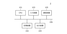
- FIG. 2 is a diagram showing an example of a hardware configuration of an image processing device 2.
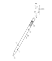
- FIG. 3 is an enlarged perspective view of the controller P. 3 is a diagram for explaining a marker 13.
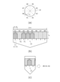
- FIG. It is a figure which shows the other example of the 1st figure F1.
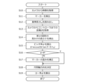
- 3 is a process flow diagram showing a process executed by the image processing device 2 to obtain the roll angle ⁇ of the controller P.
- FIG. FIG. 2 is a processing flow diagram showing processing executed by the image processing device 2 to obtain the yaw angle ⁇ and pitch angle ⁇ of the controller P.
- FIG. 1 is a diagram showing a pen-shaped controller P according to the present embodiment and an XR system 1 that generates an XR space.
- the XR system 1 includes an image processing device 2, a camera 3, and a head mounted display 4.
- the head-mounted display 4 is a type of display device that is worn on the user's head. The user wears the head-mounted display 4 and operates the controller P while viewing the XR space displayed on the display surface of the head-mounted display 4.
- the camera 3 is an imaging means arranged at a position where it can photograph the controller P, and is arranged so that the optical axis OX is horizontal.
- the x direction shown in FIG. 1 is the direction of the optical axis OX, and the y direction is a direction perpendicular to the x direction within the horizontal plane.
- the z direction is a vertical direction, and corresponds to the vertical direction of the image taken by the camera 3.
- the image processing device 2 is a computer configured to be able to execute an XR application that generates an XR space, and is connected to the camera 3 and the head-mounted display 4.
- the XR application has a function of detecting the position and orientation of the controller P based on the image of the controller P taken by the camera 3.
- the image processing device 2 running the XR application detects the position and orientation of the controller P based on the image of the camera 3, and generates a 3D object representing the controller P based on the detection result. After placing this 3D object in the generated XR space, the XR space is rendered, and the rendering result is output to the head-mounted display 4. This allows the user to operate the controller P in the XR space while viewing the 3D object on the controller P.
- FIG. 2 is a diagram showing an example of the hardware configuration of the image processing device 2.
- the image processing device 2 includes a CPU (Central Processing Unit) 101, a storage device 102, an input device 103, an output device 104, and a communication device 105.
- the specific type of the image processing device 2 is not particularly limited, and the image processing device can be processed by various types of computers, such as a notebook personal computer, a desktop personal computer, a tablet personal computer, a smartphone, and a server computer. It is possible to configure 2.
- the CPU 101 is a processor that controls each part of the image processing device 2 and reads and executes various programs stored in the storage device 102. Processing executed by the image processing device 2, which will be described later, is realized by the CPU 101 executing a program stored in the storage device 102.
- the storage device 102 is a device that includes a main storage device such as a DRAM (Dynamic Random Access Memory) and an auxiliary storage device such as a hard disk. It plays the role of storing programs and data used by these programs. Applications stored in the storage device 102 include the above-mentioned XR application.
- a main storage device such as a DRAM (Dynamic Random Access Memory)
- an auxiliary storage device such as a hard disk. It plays the role of storing programs and data used by these programs.
- Applications stored in the storage device 102 include the above-mentioned XR application.
- the input device 103 is a device that receives user input operations and supplies them to the CPU 101, and includes, for example, a keyboard, a mouse, and a touch panel.
- the camera 3 and the controller P are each one of the input devices 103.
- the camera 3 plays a role of inputting an image obtained by photographing to the image processing device 2.
- the controller P plays the role of inputting the position (position in the XR space) and orientation to the image processing apparatus 2 by having the image processing apparatus 2 detect them.
- the image processing device 2 generates the above-mentioned 3D object of the controller P based on the detected position and orientation of the controller P, and also performs processes such as moving a cursor and generating stroke data.
- the controller P may be a position indicator for a touch panel as the input device 103 of the image processing device 2.
- the touch panel in this case plays the role of detecting the position of the controller P on the touch surface and supplying the detected position to the image processing device 2.
- the output device 104 is a device that outputs the processing results of the CPU 101 to the user, and includes, for example, a display and a speaker.
- Head mounted display 4 is one of the output devices 104.
- the communication device 105 is a device for communicating with external devices including the camera 3, the controller P, and the head mounted display 4, and sends and receives data to and from these devices under the control of the CPU 101.
- FIG. 3 is an enlarged perspective view of the controller P.
- the controller P includes a housing 10 formed in, for example, a cylindrical shape, and a position indicating section 11 provided at the tip of the housing 10 to indicate a position in space.
- the user operates the controller P by grasping the housing 10 with one hand, and thereby moves the position indicating section 11 to specify a position in space.
- a plurality of light emitting diodes 12 that emit light using power supplied from the battery of the controller P, and a marker 13 formed of a predetermined figure are arranged.
- the plurality of light emitting diodes 12 are provided to allow the image processing device 2 to detect the position of the controller P, and are arranged on the surface of the controller P in a predetermined arrangement pattern.
- the image processing device 2 detects a light pattern that matches the arrangement pattern of the light emitting diodes 12 in the image supplied from the camera 3, and determines the distance between the camera 3 and the controller P based on its apparent size.
- the controller P is configured to detect the position of the controller P in the XR space by calculating .
- the number of light emitting diodes 12 to be pasted on the surface of the controller P and the specific pasting location of each light emitting diode 12 may be limited due to circumstances such as being hidden by the user's hand, so that only a portion of the plurality of light emitting diodes 12 may appear in the image.
- the controller P is determined so that the image processing device 2 can detect the position of the controller P even if the controller P does not appear.
- the marker 13 is provided for the image processing device 2 to detect the attitude of the controller P, and is arranged on the side surface of the housing 10 near the rear end so as to surround the entire circumference. The reason why the marker 13 is placed near the rear end of the housing 10 is to prevent the marker 13 from being hidden by the hand of the user holding the controller P. Detection of the posture of the controller P using the marker 13 is specifically performed by detecting the illustrated roll angle ⁇ , yaw angle ⁇ , and pitch angle ⁇ .
- the roll angle ⁇ is a rotation angle of the housing 10 around the housing axis CX (cylindrical axis).
- the yaw angle ⁇ is a rotation angle of the camera 3 around the optical axis OX.
- the pitch angle ⁇ is a rotation angle around a rotation axis RX that is orthogonal to the optical axis OX and the housing axis CX. Details of how to detect these will be described later.
- FIG. 4 is a diagram for explaining the marker 13.
- 4(a) is a cross-sectional view of the housing 10 taken along a plane perpendicular to the housing axis CX
- FIG. 4(b) is a schematic developed view of the side surface of the controller P
- FIG. 4(c) is a schematic exploded view of the side surface of the controller P. is a schematic side view of the controller P.
- the configuration of the marker 13 and the method of detecting the roll angle ⁇ will be described in detail with reference to FIG. 4 as well as FIGS. 5 and 6, which will be described later.
- the marker 13 includes a plurality of areas A1 to A8 arranged at equal pitches along the circumferential direction (circumferential direction) on the side surface of the housing 10. be done.
- areas A1 to A8 may be collectively referred to as area A when there is no need to distinguish between them.
- the number of areas A included in the marker 13 does not have to be eight. That is, the number of regions A is a parameter that determines the detection resolution of the roll angle ⁇ , and when the marker 13 includes n regions A, the detection resolution of the roll angle ⁇ is 360°/n. Therefore, the number of areas A may be determined based on the required detection resolution of the roll angle ⁇ .
- Each region A is a rectangular region of the same size.
- the arrangement pitch of the area A is ⁇ r/4.
- the width of the region A in the circumferential direction may also be ⁇ r/4, and in this case, two adjacent regions A are arranged in close contact with each other.
- the width of the area A in the circumferential direction may be set to a value smaller than ⁇ r/4, and the two adjacent areas A may be arranged apart from each other.
- FIG. 4B shows an example in which areas A1, A3 to A5 include the first figure F1, and areas A2, A6 to A8 include the second figure F2.
- the first figure F1 is an asymmetric figure having a protrusion or a depression, as shown in FIG. 4(b).
- the first figure F1 is configured in this way so that when the controller P is viewed in the image of the camera 3, the first figure F1 can be used to distinguish between the leading end and the rear end of the controller P. This is to do so.
- FIG. 4B shows a first part that is a rectangle with the same width ⁇ r/4 as area A, and the center of the upper side of the first part (side on the rear end side of controller P).
- An example is shown in which the first figure F1 is constituted by a second part (protrusion) which is a rectangle with a width ⁇ r/12 and which protrudes from the first figure F1.
- the illustrated length L0 is the width of the first figure F1 in the direction of the housing axis CX, and is stored in advance in the storage device 102 shown in FIG. 2 as a reference length L0. As will be described in detail later, the reference length L 0 thus stored in the storage device 102 is used by the controller P to calculate the pitch angle ⁇ .
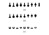
- FIG. 5 is a diagram showing another example of the first graphic F1.
- FIG. 5(a) is based on a rectangle that has long sides parallel to the housing axis CX and whose short sides are smaller than the circumferential width of area A.
- An example is shown in which the first figure F1 is constructed by adding various figures (circles, triangles, rectangles, squares, etc.) that are wide in the circumferential direction of the area A so as to be asymmetrical as a whole.
- FIG. 5(b) is based on an ellipse whose major axis is parallel to the housing axis CX and whose minor axis is smaller than the circumferential width of area A.
- FIG. 5(c) shows that the first figure is created by making a rectangular or elliptical incision from the center or corner of the rear side of the controller P in various figures such as circles, triangles, rectangles, and squares.
- An example of configuring F1 is shown. In this way, various shapes can be considered as the specific shape of the first figure F1, but the shape shown in FIG. 5 is not all. Any shape is fine.
- the second figure F2 is composed of a figure having a predetermined color (more specifically, a figure formed by solidly painting the corresponding area A with the background color). Since area A is rectangular, second figure F2 is also rectangular. Note that the background color of the marker 13 may be the same color as the side surface of the housing 10, or may be a different color. If the background color of the marker 13 is the same color as the side surface of the casing 10, it will appear to the user that nothing is arranged in the second graphic F2. Further, the second figure F2 may be composed of an asymmetric figure having a protrusion or depression similar to the first figure F1, but in this case, the first figure F1 and the second figure F2 may be formed by figures having different shapes from each other. It is necessary to configure each of the two figures F2.
- the first figure F1 and the second figure F2 each represent different bits, as illustrated in FIG. Contains code for detection.
- FIG. 4(b) shows an example in which bit “1” is associated with the first figure F1 and bit “0” is associated with the second figure F2, the reverse is also possible. Of course.
- the image of the controller P included in the image that the image processing device 2 acquires from the camera 3 includes at least three areas A as shown in FIG. 4(c).
- the type of figure (first figure F1 or second figure F2) placed in each area A is that the figure shown by three areas A included in the image is a combination of areas A, and this figure is a combination of areas A. They are selected so as to be different depending on the combination (in other words, so as not to overlap with respect to the rotation around the housing axis CX).
- the arrangement of figures shown in FIG. 4(b) is an example of such a selection.
- Table 1 shows the 3 bits represented by the three areas A appearing in the image when the first figure F1 and the second figure F2 are placed in each area A as shown in FIG. 4(b). Shows the code. From Table 1, it is understood that different combinations of the three areas A have different codes, and therefore, the three areas A appearing in the image can be determined from the codes indicated by the figures appearing in the image. Furthermore, if the roll angle ⁇ is set to 0° when the region A1 is seen directly in front, it is understood that the roll angle ⁇ can be obtained based on the code as shown in Table 1.
- the image processing device 2 detects the marker 13 appearing in the image supplied from the camera 3, and obtains a combination of figures appearing therein. Then, a 3-bit code is obtained by decoding the obtained combination of figures, and the roll angle ⁇ of the controller P is obtained based on the obtained code. In this way, according to the controller P according to the present embodiment, since the marker 13 is arranged on the surface, the image processing device 2 can obtain the roll angle ⁇ of the controller P from the image of the controller P. It becomes like this.
- FIG. 6 is a process flow diagram showing the process that the image processing device 2 executes to obtain the roll angle ⁇ of the controller P.
- the image processing device 2 first acquires an image from the camera 3 (step S1), and then detects the marker 13 included in the image (step S2). Since the marker 13 detected in this way is usually distorted, the image processing device 2 next performs processing to correct the distortion of the marker 13 (step S3).
- the process in step S3 may be performed using machine learning or inverse affine transformation.
- machine learning images of the marker 13 taken under various conditions and from various angles and images of the marker 13 seen from the front are stored in advance in the storage device 102 (see FIG. 2) of the image processing device 2. Let them learn by making connections.
- the image processing device 2 searches the storage device 102 for an image that is most similar to the image of the marker 13 detected in step S2, and selects the corrected image (image of the marker 13 seen from the front) corresponding to the hit image. Obtain as an image.
- images of the marker 13 viewed from the front are stored in advance in the storage device 102 of the image processing device 2 at various angles around the housing axis CX.
- the image processing device 2 performs various affine transformations on these images, and determines the affine transformation whose result is most similar to the image of the marker 13 detected in step S2. Then, by applying the inverse transformation of the determined affine transformation to the image of the marker 13 detected in step S2, a corrected image is obtained.
- the image processing device 2 determines the orientation of the controller P in the corrected image (step S4). Specifically, first, the first figure F1 may be detected from the image, and the direction of the controller P may be determined based on its shape. Taking the first figure F1 shown in FIG. 4(b) as an example, the image processing device 2 detects a first part and a second part from the detected first figure F1, and It is only necessary to determine that the part is located on the front end side of the controller P, and the second part is located as the rear end side of the controller P.
- the image processing device 2 decodes the marker 13 based on the orientation of the controller P determined in step S4 (step S5). Specifically, the three most visible areas A in the corrected image are determined, and the figures included in each area A are converted into bit values. Then, a 3-bit code is obtained by arranging the obtained three bit values from the left side when the tip side of the controller P is placed downward.
- the image processing device 2 calculates the roll angle ⁇ of the controller P based on the decoding result (3-bit code) in step S5 (step S6).
- the roll angle ⁇ of the controller P may be obtained by converting a 3-bit code into the roll angle ⁇ based on Table 1 described above. Detection of the roll angle ⁇ by the image processing device 2 is completed by the processing up to this point.
- FIG. 7 is a process flow diagram showing a process executed by the image processing device 2 to obtain the yaw angle ⁇ and pitch angle ⁇ of the controller P.
- the image processing device 2 first acquires an image from the camera 3 (step S10), and then detects the marker 13 included in the image (step S11).
- the processing up to this point is similar to steps S1 and S2 when acquiring the roll angle ⁇ .
- the image processing device 2 reads the above-mentioned reference length L 0 (see FIG. 4) from the storage device 102 (see FIG. 2) (step S12). Furthermore, the image processing device 2 obtains the distance d between the camera 3 and the controller P based on the position of the controller P that has been detected based on the arrangement of light from the light emitting diodes 12 shown in FIG. 3 (step S13). Furthermore, the apparent length ⁇ of the first figure F1 in the direction of the housing axis CX as seen from the camera 3 is obtained (step S14). The unit of ⁇ is angle. The image processing device 2 then calculates the pitch angle ⁇ of the controller P based on these acquired values (step S15). Specifically, the pitch angle ⁇ may be calculated using the following equation (1).
- the image processing device 2 calculates the length L1 of the first figure F1 in the housing axis CX direction as seen from the camera 3 when the pitch angle ⁇ is zero, by calibrating the controller P before starting to use it. Obtained in advance, and using this length L1 and the apparent length L (the unit of L is length) of the first figure F1 in the direction of the housing axis CX as seen from the camera 3, the following can be calculated.
- the pitch angle ⁇ may be calculated using equation (2).
- the image processing device 2 may change the ratio of the top side (the side located on the rear end side of the controller P) and the bottom side (the side located on the front end side of the controller P) of the first figure F1, or
- the pitch angle ⁇ may be calculated using a change in the aspect ratio of .
- step S16 determines whether the pitch angle ⁇ calculated in step S15 is 0 (step S16). If the image processing device 2 determines that the value is 0 as a result of the determination, the process proceeds to step S18. On the other hand, the image processing device 2 that has determined that the distortion is not 0 performs a process to correct the distortion of the marker 13 (step S17), and then advances the process to step S18.
- the process for correcting this distortion may be similar to the process described in step S3 of FIG.
- step S18 the image processing device 2 determines the direction of the housing axis CX based on the extending direction of the first figure F1. Specifically, the image processing device 2 first determines the orientation of the controller P by a process similar to step S4 in FIG. side) and the bottom side (the side located on the tip side of the controller P). Then, the positions of the midpoints of the top and bottom sides are determined, and the direction connecting the determined midpoints is determined as the direction of the housing axis CX. In addition, in cases where sufficient accuracy cannot be obtained with only the midpoint of the top side and the midpoint of the base, the midpoint of the top side of the first part (or the bottom of the second part) of the first figure F1 is also used. A line segment connecting the three midpoints may be determined by the method of least squares, and the extending direction of the determined line segment may be determined as the direction of the housing axis CX.
- step S18 it is also possible to determine the direction of the housing axis CX by machine learning.
- images of the marker 13 taken from various angles and the direction of the housing axis CX are stored in advance in the storage device 102 (see FIG. 2) of the image processing device 2 in association with each other.
- the image processing device 2 searches the storage device 102 for an image that is most similar to the image of the marker 13 detected in step S11, and obtains the direction stored in association with the hit image as the direction of the housing axis CX.
- the image processing device 2 that has determined the direction of the housing axis CX calculates the yaw angle ⁇ of the controller P by calculating the angle between the determined direction of the housing axis CX and the vertical direction (the vertical direction of the image). (Step S19). The detection of the yaw angle ⁇ and the pitch angle ⁇ by the image processing device 2 is completed by the processing up to this point.
- the controller P is a pen-shaped controller with a small surface area
- the posture of the controller P specifically Specifically, it becomes possible to detect the roll angle ⁇ , yaw angle ⁇ , and pitch angle ⁇ .
- the image processing device 2 detects the position of the controller P based on the image in which the most light-emitting diodes 12 are visible among the images taken by each camera 3, and detects the position of the controller P based on the image in which the marker 13 is most visible.
- the attitude of the controller P may be detected based on the .
- the angle from each camera 3 to the controller P may be detected, and the position of the controller P may be detected by triangulation based on the detected angle.
- the casing 10 is cylindrical
- the casing 10 is configured to have a shape other than a cylindrical shape, such as a shape having a rounded triangular cross section. You can also do it.
Landscapes
- Engineering & Computer Science (AREA)
- General Engineering & Computer Science (AREA)
- Theoretical Computer Science (AREA)
- Human Computer Interaction (AREA)
- Physics & Mathematics (AREA)
- General Physics & Mathematics (AREA)
- Length Measuring Devices By Optical Means (AREA)
- User Interface Of Digital Computer (AREA)
- Position Input By Displaying (AREA)
Abstract
Description



2 画像処理装置
3 カメラ
4 ヘッドマウントディスプレイ
10 筐体
11 位置指示部
12 発光ダイオード
13 マーカー
101 CPU
102 記憶装置
103 入力装置
104 出力装置
105 通信装置
A,A1~A8 領域
CX 筐体軸
F1 第1の図形
F2 第2の図形
OX 光軸
P コントローラ
RX 回転軸
θ ロール角
φ ヨー角
ψ ピッチ角
Claims (11)
- 筐体と、前記筐体の先端に設けられ空間における位置を指示する位置指示部と、を有するコントローラであって、
前記筐体は、前記筐体の側面に周回方向に沿って設けられるマーカーであり前記筐体の筐体軸周りの回転角を検出するためのコードを含むマーカーを有する、
コントローラ。 - 前記マーカーは、前記筐体の側面に周回方向に沿って配置された複数の領域を含み、
前記複数の領域はそれぞれ、第1の図形及び当該第1の図形と異なる第2の図形のいずれか一方を含む、
請求項1に記載のコントローラ。 - 前記第1の図形は、突起又は窪みを有する非点対称な図形である、
請求項2に記載のコントローラ。 - 前記第2の図形は、所定の色を有する図形である、
請求項2に記載のコントローラ。 - カメラによる影像に含まれるマーカーであり前記第1の図形及び前記第2の図形を有するマーカーは、前記第1の図形および前記第2の図形の組み合わせ方に応じて夫々異なるマーカーである、
請求項2乃至4のいずれか一項に記載のコントローラ。 - 前記マーカーは、前記筐体をユーザが把持した際に前記ユーザの手によって隠されない位置に配置される、
請求項1に記載のコントローラ。 - 前記マーカーは、前記筐体の後端寄りに配置される、
請求項1に記載のコントローラ。 - 前記筐体の形状は、円筒形状である、
請求項1に記載のコントローラ。 - 筐体と、前記筐体の先端に設けられ空間における位置を指示する位置指示部と、を有するコントローラの姿勢を検出するためのコンピュータであって、
前記コントローラは、前記筐体の側面に周回方向に沿って設けられるマーカーであり前記筐体の筐体軸周りの回転角であるロール角を検出するためのコードを含むマーカーを有し、
前記コンピュータは、
撮像手段を介して前記コントローラの影像を取得し、
前記影像に含まれる前記マーカーをデコードし、該デコードの結果に基づいて前記ロール角を検出する、
コンピュータ。 - 前記マーカーは、前記筐体軸に沿って延在する図形を含み、
前記コンピュータは、
前記図形の基準長さを取得し、
前記撮像手段から前記コントローラまでの距離を取得し、
前記影像に含まれる前記図形の見かけの長さを検出し、
取得した前記基準長さ、前記距離、及び前記見かけの長さに基づいて、前記撮像手段の光軸と前記筐体軸に直交する回転軸周りの回転角であるピッチ角を検出する、
請求項9に記載のコンピュータ。 - 前記コンピュータは、
前記図形の延在方向に基づいて前記筐体軸の方向を決定し、
垂直方向及び前記筐体軸の方向に基づいて、前記撮像手段の光軸周りの回転角であるヨー角を検出する、
請求項10に記載のコンピュータ。
Priority Applications (3)
| Application Number | Priority Date | Filing Date | Title |
|---|---|---|---|
| CN202280092655.9A CN118696293A (zh) | 2022-03-25 | 2022-12-26 | 控制器及计算机 |
| JP2024509772A JPWO2023181568A1 (ja) | 2022-03-25 | 2022-12-26 | |
| US18/895,218 US12572223B2 (en) | 2022-03-25 | 2024-09-24 | Controller and computer |
Applications Claiming Priority (2)
| Application Number | Priority Date | Filing Date | Title |
|---|---|---|---|
| JP2022-049337 | 2022-03-25 | ||
| JP2022049337 | 2022-03-25 |
Related Child Applications (1)
| Application Number | Title | Priority Date | Filing Date |
|---|---|---|---|
| US18/895,218 Continuation US12572223B2 (en) | 2022-03-25 | 2024-09-24 | Controller and computer |
Publications (1)
| Publication Number | Publication Date |
|---|---|
| WO2023181568A1 true WO2023181568A1 (ja) | 2023-09-28 |
Family
ID=88100972
Family Applications (1)
| Application Number | Title | Priority Date | Filing Date |
|---|---|---|---|
| PCT/JP2022/047895 Ceased WO2023181568A1 (ja) | 2022-03-25 | 2022-12-26 | コントローラ及びコンピュータ |
Country Status (5)
| Country | Link |
|---|---|
| US (1) | US12572223B2 (ja) |
| JP (1) | JPWO2023181568A1 (ja) |
| CN (1) | CN118696293A (ja) |
| TW (1) | TW202338572A (ja) |
| WO (1) | WO2023181568A1 (ja) |
Citations (3)
| Publication number | Priority date | Publication date | Assignee | Title |
|---|---|---|---|---|
| JP2005055177A (ja) * | 2002-01-18 | 2005-03-03 | Nippon Telegr & Teleph Corp <Ntt> | 3次元位置・姿勢検出用立体、3次元位置・姿勢検出方法、3次元位置・姿勢検出装置、3次元位置・姿勢検出プログラム、および該プログラムを記録した記録媒体 |
| JP2020140685A (ja) * | 2019-02-22 | 2020-09-03 | シャープ株式会社 | 入力装置及び入力システム |
| JP2021518953A (ja) * | 2018-05-02 | 2021-08-05 | エスゼット ディージェイアイ テクノロジー カンパニー リミテッドSz Dji Technology Co.,Ltd | ナビゲートする方法及びシステム |
Family Cites Families (13)
| Publication number | Priority date | Publication date | Assignee | Title |
|---|---|---|---|---|
| US5818424A (en) * | 1995-10-19 | 1998-10-06 | International Business Machines Corporation | Rod shaped device and data acquisition apparatus for determining the position and orientation of an object in space |
| US6720949B1 (en) * | 1997-08-22 | 2004-04-13 | Timothy R. Pryor | Man machine interfaces and applications |
| US20050037844A1 (en) * | 2002-10-30 | 2005-02-17 | Nike, Inc. | Sigils for use with apparel |
| US6795068B1 (en) * | 2000-07-21 | 2004-09-21 | Sony Computer Entertainment Inc. | Prop input device and method for mapping an object from a two-dimensional camera image to a three-dimensional space for controlling action in a game program |
| US9229540B2 (en) * | 2004-01-30 | 2016-01-05 | Electronic Scripting Products, Inc. | Deriving input from six degrees of freedom interfaces |
| US7775439B2 (en) * | 2007-01-04 | 2010-08-17 | Fuji Xerox Co., Ltd. | Featured wands for camera calibration and as a gesture based 3D interface device |
| US9443311B2 (en) * | 2014-06-12 | 2016-09-13 | Topcon Positioning Systems, Inc. | Method and system to identify a position of a measurement pole |
| US10249090B2 (en) * | 2016-06-09 | 2019-04-02 | Microsoft Technology Licensing, Llc | Robust optical disambiguation and tracking of two or more hand-held controllers with passive optical and inertial tracking |
| GB2571953A (en) * | 2018-03-13 | 2019-09-18 | Massless Emea Ltd | Single view tracking of cylindrical objects |
| CN121957360A (zh) | 2018-05-18 | 2026-05-01 | 株式会社和冠 | 位置指示装置、计算机及控制方法 |
| US10719143B2 (en) * | 2018-08-03 | 2020-07-21 | Logitech Europe S.A. | Input device for use in an augmented/virtual reality environment |
| JP7353773B2 (ja) * | 2019-03-18 | 2023-10-02 | 株式会社ソニー・インタラクティブエンタテインメント | 複数のマーカを備えたデバイス |
| US11886650B2 (en) * | 2019-04-19 | 2024-01-30 | Apple Inc. | Stylus-based input system for a head-mounted device |
-
2022
- 2022-12-26 WO PCT/JP2022/047895 patent/WO2023181568A1/ja not_active Ceased
- 2022-12-26 JP JP2024509772A patent/JPWO2023181568A1/ja active Pending
- 2022-12-26 CN CN202280092655.9A patent/CN118696293A/zh active Pending
-
2023
- 2023-01-05 TW TW112100342A patent/TW202338572A/zh unknown
-
2024
- 2024-09-24 US US18/895,218 patent/US12572223B2/en active Active
Patent Citations (3)
| Publication number | Priority date | Publication date | Assignee | Title |
|---|---|---|---|---|
| JP2005055177A (ja) * | 2002-01-18 | 2005-03-03 | Nippon Telegr & Teleph Corp <Ntt> | 3次元位置・姿勢検出用立体、3次元位置・姿勢検出方法、3次元位置・姿勢検出装置、3次元位置・姿勢検出プログラム、および該プログラムを記録した記録媒体 |
| JP2021518953A (ja) * | 2018-05-02 | 2021-08-05 | エスゼット ディージェイアイ テクノロジー カンパニー リミテッドSz Dji Technology Co.,Ltd | ナビゲートする方法及びシステム |
| JP2020140685A (ja) * | 2019-02-22 | 2020-09-03 | シャープ株式会社 | 入力装置及び入力システム |
Non-Patent Citations (1)
| Title |
|---|
| NOBUYOSHI HASHIMOTO: "PI-18-043 Cylindrical marker for real-time tracking of pen-shaped implements", THE PAPERS OF TECHNICAL MEETING ON "PERCEPTION INFORMATION"; JUNE 2-3, 2018, IEE JAPAN, JP, vol. 40-48, 2 June 2018 (2018-06-02) - 3 June 2018 (2018-06-03), JP, pages 17 - 20, XP009549930 * |
Also Published As
| Publication number | Publication date |
|---|---|
| JPWO2023181568A1 (ja) | 2023-09-28 |
| US12572223B2 (en) | 2026-03-10 |
| US20250036212A1 (en) | 2025-01-30 |
| TW202338572A (zh) | 2023-10-01 |
| CN118696293A (zh) | 2024-09-24 |
Similar Documents
| Publication | Publication Date | Title |
|---|---|---|
| JP6330879B2 (ja) | ヨー・ユーザインターフェイス | |
| JP4323472B2 (ja) | 多角形チャート描画処理方法およびプログラム | |
| US10204404B2 (en) | Image processing device and image processing method | |
| CN102221878A (zh) | 图像处理系统、图像处理装置、图像处理方法及程序 | |
| JP5656514B2 (ja) | 情報処理装置及び方法 | |
| US7627137B2 (en) | Image composition system, image composition method, and image composition apparatus | |
| CN107230239A (zh) | 图形绘制方法、装置及设备 | |
| CN103177135A (zh) | 三次元坐标系图形化创建系统及方法 | |
| JP6777391B2 (ja) | 3次元相互作用のためのコンピュータ装置及び方法 | |
| US20250295390A1 (en) | Ultrasound scanner with display interface | |
| JP2009134677A (ja) | ジェスチャインターフェースシステム、ジェスチャ入力用ワンド、アプリケーション制御方法、カメラ校正方法、及び制御プログラム | |
| JP2009134677A6 (ja) | ジェスチャインターフェースシステム、ジェスチャ入力用ワンド、アプリケーション制御方法、カメラ校正方法、及び制御プログラム | |
| US12026326B2 (en) | Pen state detection circuit and method, and input system | |
| US10281804B2 (en) | Image processing apparatus, image processing method, and program | |
| US10983605B2 (en) | Three-dimensional object position tracking system | |
| KR20200098596A (ko) | 입체를 인식하기 위한 프로그램, 시스템, 전자 장치 및 방법 | |
| WO2023181568A1 (ja) | コントローラ及びコンピュータ | |
| CN111897432B (zh) | 位姿确定方法、装置和电子设备 | |
| JP3276949B2 (ja) | 3次元有向体の定位方法及び画像処理装置 | |
| CN110096134A (zh) | 一种vr手柄射线抖动矫正方法、装置、终端和介质 | |
| JP7762662B2 (ja) | コンピュータ、方法、及びプログラム | |
| JP7378865B1 (ja) | 三次元オブジェクトの画像を生成する方法及びプログラム | |
| US20250123678A1 (en) | Cross-reality device, storage medium, processing device, generation method, and processing method | |
| CN120107452A (zh) | 三维物体交互点的坐标映射方法、装置、设备及介质 | |
| WO2025258620A1 (ja) | コンピュータ、方法、及びプログラム |
Legal Events
| Date | Code | Title | Description |
|---|---|---|---|
| 121 | Ep: the epo has been informed by wipo that ep was designated in this application |
Ref document number: 22933695 Country of ref document: EP Kind code of ref document: A1 |
|
| WWE | Wipo information: entry into national phase |
Ref document number: 2024509772 Country of ref document: JP |
|
| WWE | Wipo information: entry into national phase |
Ref document number: 202280092655.9 Country of ref document: CN |
|
| NENP | Non-entry into the national phase |
Ref country code: DE |
|
| 122 | Ep: pct application non-entry in european phase |
Ref document number: 22933695 Country of ref document: EP Kind code of ref document: A1 |