WO2023181237A1 - 非接触入力装置及び非接触入力方法 - Google Patents
非接触入力装置及び非接触入力方法 Download PDFInfo
- Publication number
- WO2023181237A1 WO2023181237A1 PCT/JP2022/013860 JP2022013860W WO2023181237A1 WO 2023181237 A1 WO2023181237 A1 WO 2023181237A1 JP 2022013860 W JP2022013860 W JP 2022013860W WO 2023181237 A1 WO2023181237 A1 WO 2023181237A1
- Authority
- WO
- WIPO (PCT)
- Prior art keywords
- aerial
- coordinates
- dimensional
- range
- coordinate
- Prior art date
- Legal status (The legal status is an assumption and is not a legal conclusion. Google has not performed a legal analysis and makes no representation as to the accuracy of the status listed.)
- Ceased
Links
Images









Classifications
-
- G—PHYSICS
- G06—COMPUTING OR CALCULATING; COUNTING
- G06F—ELECTRIC DIGITAL DATA PROCESSING
- G06F3/00—Input arrangements for transferring data to be processed into a form capable of being handled by the computer; Output arrangements for transferring data from processing unit to output unit, e.g. interface arrangements
- G06F3/01—Input arrangements or combined input and output arrangements for interaction between user and computer
- G06F3/03—Arrangements for converting the position or the displacement of a member into a coded form
- G06F3/041—Digitisers, e.g. for touch screens or touch pads, characterised by the transducing means
- G06F3/042—Digitisers, e.g. for touch screens or touch pads, characterised by the transducing means by opto-electronic means
- G06F3/0425—Digitisers, e.g. for touch screens or touch pads, characterised by the transducing means by opto-electronic means using a single imaging device like a video camera for tracking the absolute position of a single or a plurality of objects with respect to an imaged reference surface, e.g. video camera imaging a display or a projection screen, a table or a wall surface, on which a computer generated image is displayed or projected
-
- G—PHYSICS
- G06—COMPUTING OR CALCULATING; COUNTING
- G06F—ELECTRIC DIGITAL DATA PROCESSING
- G06F3/00—Input arrangements for transferring data to be processed into a form capable of being handled by the computer; Output arrangements for transferring data from processing unit to output unit, e.g. interface arrangements
- G06F3/01—Input arrangements or combined input and output arrangements for interaction between user and computer
- G06F3/03—Arrangements for converting the position or the displacement of a member into a coded form
- G06F3/033—Pointing devices displaced or positioned by the user, e.g. mice, trackballs, pens or joysticks; Accessories therefor
- G06F3/0346—Pointing devices displaced or positioned by the user, e.g. mice, trackballs, pens or joysticks; Accessories therefor with detection of the device orientation or free movement in a three-dimensional [3D] space, e.g. 3D mice, 6-DOF [six degrees of freedom] pointers using gyroscopes, accelerometers or tilt-sensors
-
- G—PHYSICS
- G06—COMPUTING OR CALCULATING; COUNTING
- G06F—ELECTRIC DIGITAL DATA PROCESSING
- G06F3/00—Input arrangements for transferring data to be processed into a form capable of being handled by the computer; Output arrangements for transferring data from processing unit to output unit, e.g. interface arrangements
- G06F3/01—Input arrangements or combined input and output arrangements for interaction between user and computer
- G06F3/03—Arrangements for converting the position or the displacement of a member into a coded form
- G06F3/041—Digitisers, e.g. for touch screens or touch pads, characterised by the transducing means
- G06F3/0416—Control or interface arrangements specially adapted for digitisers
- G06F3/0418—Control or interface arrangements specially adapted for digitisers for error correction or compensation, e.g. based on parallax, calibration or alignment
-
- G—PHYSICS
- G06—COMPUTING OR CALCULATING; COUNTING
- G06F—ELECTRIC DIGITAL DATA PROCESSING
- G06F2203/00—Indexing scheme relating to G06F3/00 - G06F3/048
- G06F2203/041—Indexing scheme relating to G06F3/041 - G06F3/045
- G06F2203/04101—2.5D-digitiser, i.e. digitiser detecting the X/Y position of the input means, finger or stylus, also when it does not touch, but is proximate to the digitiser's interaction surface and also measures the distance of the input means within a short range in the Z direction, possibly with a separate measurement setup
Definitions
- the present disclosure relates to a non-contact input device and a non-contact input method.
- a real image surface containing various input areas such as buttons is projected onto a specific area in the air, the entry of an operating device such as a finger into that surface is detected, and various actions are performed according to the coordinates at which the operating device enters.
- an operating device such as a finger into that surface
- various actions are performed according to the coordinates at which the operating device enters.
- one or more aspects of the present disclosure aim to eliminate noise when an operating means is detected and to detect the coordinates thereof with high accuracy when inputting an operation without contact. do.
- a non-contact input device sequentially detects three-dimensional operation coordinates, which are coordinates of three axes in a predetermined space, of an instruction input object, which is an object for inputting an instruction, to Smoothing using a three-dimensional operating coordinate detection unit that detects three-dimensional operating coordinates, and a first number of three-dimensional operating coordinates that are a predetermined number of two or more included in the plurality of three-dimensional operating coordinates.
- a smoothing processing unit that calculates smoothed three-dimensional operation coordinates and the smoothed three-dimensional operation coordinates are used to determine that the instruction input object is within the aerial reception range that is a predetermined range in the space.
- the vehicle is characterized by comprising a passage determination unit that specifies passage coordinates that are coordinates that have been passed.
- a non-contact input method sequentially detects three-dimensional operation coordinates, which are coordinates of three axes in a predetermined space, of an instruction input object, which is an object for inputting instructions. Smoothing by detecting three-dimensional operation coordinates and performing smoothing using a first number of three-dimensional operation coordinates, which is a predetermined number of two or more, included in the plurality of three-dimensional operation coordinates. calculating three-dimensional operation coordinates, and using the smoothed three-dimensional operation coordinates, specifying passing coordinates that are coordinates at which the instruction input object passes through an aerial reception range that is a predetermined range in the space; Features.
- FIG. 1 is a perspective view showing the appearance of a non-contact input device according to Embodiments 1 to 4.
- FIG. 1 is a block diagram schematically showing the configuration of a non-contact input device in Embodiments 1 to 3.
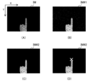
- FIG. (A) to (D) are schematic diagrams for explaining a method for detecting three-dimensional operation coordinates.
- FIG. 2 is a schematic diagram for explaining an imaging device coordinate system.
- FIG. 2 is a schematic diagram for explaining the correspondence between an image pickup device coordinate system and an aerial reception range coordinate system.
- (A) and (B) are block diagrams showing examples of hardware configurations.
- 7 is a flowchart illustrating an operation for determining whether an instruction input object has passed through one aerial acceptance range in the first embodiment.
- FIG. 3 is a perspective view for explaining an aerial reception range. 12 is a flowchart illustrating an operation of specifying processing based on input to an aerial reception range. It is a graph for explaining a situation where chattering occurs. This is a graph for explaining a method for eliminating chattering.
- FIG. 3 is a schematic diagram showing a projected image in Embodiment 2.
- FIG. FIG. 7 is a diagram illustrating the vicinity of the aerial reception range in Embodiment 2, cut along a plane perpendicular to the y-axis.
- FIG. 12 is a flowchart illustrating an operation for determining whether an instruction input object has passed through one aerial reception range in the second embodiment.
- FIG. 7 is a schematic diagram showing a modification of the aerial reception range in Embodiment 2.
- FIG. (A) to (C) are graphs for explaining in detail the operation of the aerial acceptance range passage determination unit in the third embodiment.
- (A) and (B) are schematic diagrams showing the configuration of a two-stage cascade type IIR filter. 2 is a graph showing group delay characteristics of a two-stage cascade type IIR filter.
- FIG. 7 is a block diagram schematically showing the configuration of a non-contact input device in Embodiment 4.
- FIG. 12 is a flowchart showing an operation for determining whether an instruction input object has passed through one aerial reception range in Embodiment 4.
- (A) to (C) are graphs for explaining the operation of the aerial acceptance range passage determination section.
- FIG. 1 is a perspective view showing the appearance of a non-contact input device 100 according to the first embodiment.
- the non-contact input device 100 projects an aerial image 102 in a predetermined space using a mechanism installed inside the housing 101.
- a mechanism for projecting the aerial image 102 a known technique may be used, so a detailed description thereof will be omitted.
- a display is mounted in the housing 101, and an aerial image 102 is projected by re-imaging the light emitted from the display in space using a retroreflector and a half mirror. can do. Note that other means may be used as the mechanism for performing this projection.
- buttons 103a, 103b, and 103c which are aerial input receiving surfaces, are displayed.
- Instruction content to the non-contact input device 100 is assigned to each of the buttons 103a, 103b, and 103c.
- the button 103a is assigned a "determination” instruction
- the button 103b is assigned a "cancel” instruction
- the button 103c is assigned a "setting” instruction. Note that if there is no need to distinguish between the buttons 103a, 103b, and 103c, one of the buttons 103a, 103b, and 103c will be referred to as button 103.
- each of the buttons 103a, 103b, and 103c is associated with an aerial reception range that is a range that accepts input of instructions from the user.
- an instruction input object such as a finger enters the aerial reception range associated with the button 103a
- the non-contact input device 100 detects that the instruction assigned to the button 103a has been input. judge it as something.
- the instruction input object is an object for inputting instructions, and is used for inputting instructions.
- the instruction input object is a finger or a protrusion such as a stick.
- the aerial reception range may be a part of the aerial image 102. Further, the aerial reception range may be offset from the associated button 103, inclined from the associated button 103, or bent relative to the associated button 103, etc. , it does not have to match the button 103 shown in the aerial image 102. Furthermore, the aerial receiving range may have a three-dimensional thick shape, such as a rectangular parallelepiped or a sphere, in addition to a flat or curved surface.
- the user of the non-contact input device 100 instructs the non-contact input device 100 by moving an instruction input object such as a finger into the aerial reception range associated with the button 103 of the desired content. Detection of whether or not this instruction input object has entered the aerial reception range is carried out by setting the aerial reception range, which is installed in the casing 101 of the non-contact input device 100 and corresponds to the buttons 103a, 103b, and 103c, into the imaging range. This is done using an image capture device 104 that includes.
- the image capture device 104 is a detection device that can capture three-dimensional images.
- the image capturing device 104 is, for example, a three-dimensional image capturing device using a TOF (Time of Flight) method.
- the TOF type three-dimensional image pickup device is only one example, and the image pickup device 104 may be a detection device capable of acquiring three-dimensional information, such as a twin-lens stereo camera, an active stereo type camera, or LiDAR. Any device may be used.
- the non-contact input device 100 When an instruction is given, the non-contact input device 100 outputs an operation acceptance sound from the speaker 105 as feedback to the user.
- feedback is provided by sound, but this is just one example; for example, a pseudo tactile sensation is provided by emitting light, vibration, or ultrasonic waves to the finger, or any of these methods is used. Feedback may be provided in combination.
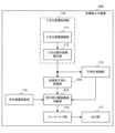
- FIG. 2 is a block diagram schematically showing the configuration of non-contact input device 100 in the first embodiment.
- the non-contact input device 100 includes a three-dimensional coordinate acquisition section 110, a smoothing processing section 113, an aerial image projection section 114, an aerial acceptance range passage determination section 115, a feedback section 116, and an output section 117.
- the three-dimensional coordinate acquisition unit 110 acquires three-dimensional operation coordinates that are the three-dimensional coordinates of the instruction input object.
- the three-dimensional coordinate acquisition unit 110 includes a three-dimensional image capturing unit 111 and a three-dimensional operation coordinate detection unit 112.
- the three-dimensional image capturing unit 111 is a functional unit realized by the image capturing device 104 in FIG.
- the three-dimensional image capturing section 111 captures a three-dimensional image IM and provides the three-dimensional image IM to the three-dimensional operation coordinate detecting section 112 .
- the three-dimensional image capturing unit 111 outputs a three-dimensional image IM, which is a three-dimensional image of a predetermined space, so as to include an aerial image projected by an aerial image projecting unit 114, which will be described later. .
- the three-dimensional operation coordinate detection unit 112 detects three-dimensional operation coordinates C, which are coordinates of the three axes of the instruction input object, from the three-dimensional image IM.
- the three-dimensional operation coordinate detection unit 112 detects a plurality of three-dimensional operation coordinates C at different times by sequentially detecting the three-dimensional operation coordinates C of the instruction input object.
- FIGS. 3A to 3D are schematic diagrams for explaining a method for detecting the three-dimensional operation coordinate C.
- FIG. 3(A) shows a three-dimensional image IM.
- the three-dimensional image IM here is represented by a horizontal axis X and a vertical axis Y, and is a distance image in which the shading of pixels indicates the distance from the image capturing device 104.
- the distance indicates that a pixel with higher luminance is closer to the image capturing device 104.
- FIG. 3(B) shows a binarized three-dimensional image IM#1 generated by binarizing the three-dimensional image IM shown in FIG. 3(A).
- the three-dimensional operation coordinate detection unit 112 generates a binarized three-dimensional image IM#1 by binarizing the three-dimensional image IM. Binarization is performed to distinguish between points on a pointing input object such as a finger and other points. Therefore, it is assumed that a threshold value is determined so that such a distinction can be made appropriately. For example, as shown in FIG. 1, when the image capture device 104 is installed facing downward, the threshold value is farther than the farthest end of the aerial reception range corresponding to each of the buttons 103a, 103b, and 103c. It is desirable to set it to a value closer to the ground.
- FIG. 3(C) is a schematic diagram showing the noise-removed three-dimensional image IM#2.
- Distance images generally contain relatively large noise. Therefore, a lot of fine noise is included in the binarized three-dimensional image IM#1 shown in FIG. 3(B).
- the three-dimensional operation coordinate detection unit 112 can detect the noise-removed three-dimensional image IM#2 shown in FIG. 3(C). Noise is removed. Note that various other methods can be applied to noise removal, such as a method using a median filter or a method of performing an opening after a closing.
- the three-dimensional operation coordinate detection unit 112 detects the tip of the finger, which is the instruction input object, from the noise-removed three-dimensional image IM#2, as shown in FIG. 3(D).
- the negative side of the Y-axis is the user side of the aerial plane, and the positive side of the Y-axis is the casing 101 side. Therefore, since the finger enters from the minus side to the plus side of the Y-axis, the tip of the finger simply becomes the point with the smallest Y-axis coordinate among the detected closed regions. In FIG. 3(D), this point is indicated by a batten symbol.
- the X and Y coordinates of the tip point are determined. Furthermore, since the distance of this point becomes the depth Z obtained from the brightness of the (X, Y) pixel in the original three-dimensional image IM, the three-dimensional coordinates (X, Y, Z) are determined.
- the three-dimensional operation coordinate detection unit 112 expresses the three-dimensional coordinates (X, Y, Z) in an imaging device coordinate system, which is a coordinate system with the three-dimensional image capturing unit 111 as the origin.
- the imaging device coordinate system has the origin at the tip of the optical axis of the lens 104a of the imaging device 104 used as the three-dimensional image imaging unit 111, and the long axis side is the x c axis, the short axis is This is a coordinate system in which the axial side is the y c axis and the optical axis direction is the z c axis.
- the imaging area spreads radially, so if the Z coordinate is different for the same X or Y coordinate, the x c or y c value will be different. .
- the method of converting the image into three-dimensional coordinates as described above is just one example, and various other methods such as pattern matching or a method using a learning device can be applied.
- the imaging three-dimensional coordinates (x c , y c , z c ) obtained in this way require further conversion if the imaging machine coordinate system and the coordinate system of the aerial reception range are different.
- This transformation is performed by converting the imaging three-dimensional coordinates (x c , y c , z c ) expressed in the imager coordinate system into a three-dimensional operation expressed in the aerial reception range coordinate system having the x-axis, y-axis, and z-axis. It is defined as converting to coordinate C.
- FIG. 5 is a schematic diagram for explaining the correspondence between the imaging device coordinate system and the aerial reception range coordinate system. Note that this conversion is performed for the number of aerial reception ranges R, but in FIG. 5, only one aerial reception range R1 is shown to simplify the explanation.
- the aerial reception range R1 associated with a certain button 103 is assumed to be (
- ⁇ y max , z 0).
- the origin of the aerial reception range coordinate system is (x c0 , y c0 , z c0 ) in the imager coordinates, the rotation around the x c axis is ⁇ , the rotation around the y c axis is ⁇ , and the rotation around the z c axis is ⁇
- the imaging three-dimensional coordinates (x c , y c , z c ) are converted to the three-dimensional operation coordinates C of the aerial reception range coordinate system (x, y, z). can be converted to .
- the smoothing processing unit 113 performs smoothing using a first number of three-dimensional operating coordinates C, which is a predetermined number of two or more, included in the plurality of three-dimensional operating coordinates C. In this way, the smoothed three-dimensional operation coordinate SC is calculated.
- the smoothing processing unit 113 smoothes the three-dimensional operation coordinate C in the time direction and provides the result to the aerial acceptance range passage determination unit 115 as the smoothed three-dimensional operation coordinate SC.
- the smoothing method in this embodiment is smoothing using a 7-tap moving average. Let (x, y, z) at time t be x(t), y(t), and z(t), and the smoothing processing unit 113 calculates the smoothed three-dimensional operating coordinate SC using the following equation (3). do. (3)
- a moving average filter is used as a smoothing means, but this embodiment is not limited to such an example.
- various means can be applied, such as means using an FIR (Finite Impulse Response) digital filter of another coefficient such as a window function method, or an IIR (Infinite Impulse Response) digital filter, etc. as a smoothing filter. .
- the aerial image projection unit 114 projects an aerial image having a portion associated with the aerial reception range onto a predetermined space.
- the aerial image projection unit 114 projects an aerial image 102 as shown in FIG.
- the portions associated with the aerial reception range are buttons 130a to 130c.
- the technique of projecting the aerial image any known technique may be used.
- the aerial image projection unit 114 provides the aerial acceptance range passage determination unit 115 with aerial acceptance range information indicating the aerial acceptance range R in the aerial acceptance range coordinate system.
- the aerial acceptance range passage determining unit 115 determines whether the finger, which is an example of the instruction input object, is in the aerial acceptance range R based on the three-dimensional operation coordinates C and the aerial acceptance range R indicated by the aerial acceptance range information from the aerial image projection unit 114. This is a passage determination unit that determines whether or not the vehicle has passed through. Then, the aerial acceptance range passage determination unit 115 provides a passage determination result P indicating the determination result to the feedback unit 116.
- the aerial acceptance range passage determining unit 115 uses a predetermined function to determine whether the air is in the air or It is determined whether the instruction input object has passed through the reception range R. For example, the aerial acceptance range passage determination unit 115 sequentially inputs a plurality of three-dimensional operation coordinates into the function, and when the output of the function becomes larger or smaller than the value, the air acceptance range passage determination unit 115 determines whether the air acceptance range It can be determined whether the instruction input object has passed through R or not.
- f(x, y, z) changes from positive to negative or from negative to positive
- it always passes through the aerial reception range R, which is set as f(x, y, z) 0. That will happen. Therefore, by confirming the value of f (x, y, z) into which the three-dimensional operation coordinate C is input, the aerial reception range passage determining unit 115 determines the air reception range by using the three-dimensional operation coordinate C. It can be determined whether the input object has passed through.
- the aerial acceptance range passage determining unit 115 uses the smoothed three-dimensional operation coordinates SC to identify passing coordinates that are the coordinates at which the instruction input object has passed through the aerial acceptance range R. Specifically, the aerial acceptance range passage determining unit 115 determines which coordinates in the aerial acceptance range R the finger, which is the instruction input object, has passed using the smoothed three-dimensional operation coordinates SC from the smoothing processing unit 113. Specify the passing coordinate CSC shown.
- the passage coordinate CSC is calculated from the three-dimensional operation coordinate C using the above equation (3) at time t when it is determined that the finger, which is an example of the instruction input object, has passed through the aerial reception range R. It is composed of an x-axis value and a y-axis value.
- the aerial acceptance range passage determination unit 115 determines that the instruction input object has passed through the aerial acceptance range R, in other words, the input object is input to the aerial acceptance range R. It is determined that this has taken place.
- the aerial acceptance range passage determination unit 115 specifies the value of the first axis extending in the direction intersecting the aerial acceptance range R from the three-dimensional operation coordinate C among the three axes.
- the aerial acceptance range passage determining unit 115 uses the specified value to specify the time when the instruction input object passes through the aerial acceptance range R.
- the aerial acceptance range passage judgment unit 115 calculates the values of the second and third axes, which are obtained by excluding the first axis from the three axes, at the specified time from the smoothed three-dimensional operation coordinate SC as the passage coordinate CSC. Identify. Then, when the passing coordinate CSC is within the aerial acceptance range R, the aerial acceptance range passage determining unit 115 determines that an input has been made to the aerial acceptance range R.
- the first axis is the z-axis
- the second and third axes are the x-axis and the y-axis.
- the feedback unit 116 refers to the passage determination result P, and provides feedback if the determination is true, in other words, it indicates that the instruction input object has passed through the aerial acceptance range R. Specifically, the feedback unit 116 causes the output unit 117 serving as the speaker 105 to output an operation acceptance sound, for example.
- the output unit 117 performs output to the outside of the non-contact input device 100 in response to instructions from the feedback unit 116.
- the feedback unit 116 gives an instruction when the instruction input object passes through the aerial reception range R.
- the output unit 117 outputs feedback to the user.
- the output unit 117 is the speaker 105 shown in FIG. 1, the output unit 117 outputs an operation acceptance sound.
- the output unit 117 is not limited to the speaker 105 that outputs sound, and may be other means such as a display. Further, the output unit 117 may output ultrasonic waves that give a tactile sensation to the instruction input object.
- a part or all of the three-dimensional operation coordinate detection unit 112, smoothing processing unit 113, aerial acceptance range passage determination unit 115, and feedback unit 116 described above may be configured as shown in FIG. 6(A), for example.
- it can be configured by a memory 10 and a processor 11 such as a CPU (Central Processing Unit) that executes a program stored in the memory 10.
- a program may be provided through a network, or may be provided recorded on a recording medium. That is, such a program may be provided as a program product, for example.
- the processing circuit 12 may be a single circuit, a composite circuit, a processor operated by a program, a parallel processor operated by a program, an ASIC (Application Specific Integrated Circuit), or an FPGA (Field Programmable Gate Array).
- the three-dimensional operation coordinate detection section 112, the smoothing processing section 113, the aerial acceptance range passage determination section 115, and the feedback section 116 can be realized by a processing circuit network.
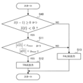
- FIG. 7 is a flowchart showing the operation of determining whether an instruction input object has passed through one aerial reception range R in the first embodiment.
- the aerial reception range R is the aerial reception range R1 (
- ⁇ y max , z 0), as shown in FIG.
- the aerial acceptance range passage determination unit 115 determines that z(t-1), which is the value of the z coordinate at time t-1 in the three-dimensional operation coordinate C, is positive or 0, and that It is determined whether z(t), which is the value of the z coordinate at time t, is negative (S10). Note that when the frame rate is 30 frames per second, the time difference between time t-1 and time t is 1/30 second, which is the time difference of one frame.
- the origin is set on the aerial reception range R1
- the upper part of the vertical line of the aerial reception range R1 is positive
- the value used for the determination is the three-dimensional operation coordinate C, which is the value before smoothing. This is because the smoothed three-dimensional operation coordinate SC has a delay in exchange for reducing errors, so if the smoothed three-dimensional operation coordinate SC is used, the judgment will also be delayed. On the other hand, since the immediacy of the reaction is important for the performance of the device, a three-dimensional operating coordinate C is used here.
- the aerial acceptance range passage determination unit 115 determines that the passage coordinate CSC, which is the smoothed value of the x-coordinate value and the smoothed value of the y-coordinate value at time t in the smoothed three-dimensional operation coordinate SC, is It is determined whether the following equations (4) and (5) are satisfied (S11). (4) (5)
- step S11 If both equations (4) and (5) are satisfied (Yes in S11), the process proceeds to step S12, and if at least one of equations (4) and (5) is not satisfied (S11 (No), the process proceeds to step S13.
- step S12 the aerial reception range passage determination unit 115 determines that the instruction input object has passed through one target aerial reception range R.
- the aerial reception range passage determination unit 115 determines that the instruction input object has not passed through one target aerial reception range R.
- the aerial reception range passage determination unit 115 can specify which aerial reception range R. It is possible to specify whether the input object has passed.
- the determination in step S11 is determining whether the smoothed three-dimensional operation coordinate SC is within the aerial reception range R. This is, for example, a judgment that specifies which button 103 on the screen has been pressed, and in order to substantially increase the resolution, it is necessary to use smoothed three-dimensional operation coordinates SC, which are highly accurate coordinates. be.
- a delay occurs as a trade-off, when the user of the non-contact input device 100 as in this embodiment actually operates the button 103 in the air, there is a tendency to move the finger in a direction perpendicular to the button 103. is known, and when moving the finger in this direction, the x and y coordinates will be approximately constant, so a slight delay will not be a problem.
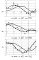
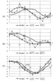
- FIGS. 8(A) to 8(C) are graphs for explaining in detail the differences between passage determination and coordinate determination as described above.
- FIG. 8(A) shows the x-axis value of the actual finger movement, the x-axis value of the three-dimensional operation coordinate C, and the x-axis value of the smoothed three-dimensional operation coordinate SC in the aerial reception range coordinate system. It is a graph showing a time series of. The horizontal axis of FIG. 8(A) indicates time, and the vertical axis indicates the value of the x-axis.
- FIG. 8(B) shows the y-axis value of the actual finger movement, the y-axis value of the three-dimensional operation coordinate C, and the y-axis value of the smoothed three-dimensional operation coordinate SC in the aerial reception range coordinate system. It is a graph showing a time series of. The horizontal axis of FIG. 8(B) indicates time, and the vertical axis indicates the value of the y-axis.
- FIG. 8(C) shows the z-axis value of the actual finger movement, the z-axis value of the three-dimensional operation coordinate C, and the z-axis value of the smoothed three-dimensional operation coordinate SC in the aerial reception range coordinate system. It is a graph showing a time series of. The horizontal axis of FIG. 8(C) indicates time, and the vertical axis indicates the value of the z-axis.
- the solid line is the true value as the actual finger coordinate
- the broken line is the value of the measured three-dimensional operation coordinate C
- the double line is the value of the smoothed three-dimensional operating coordinate SC obtained by smoothing the value of the three-dimensional operating coordinate C.
- the value of the three-dimensional operating coordinate C shown by the broken line has an error added compared to the true value shown by the solid line, and vibration are doing.
- the value of the smoothed three-dimensional operating coordinate SC shown by a double line has a reduced error compared to the value of the three-dimensional operating coordinate C shown by a broken line, but it is shown by a solid line. There is a delay of about three frames compared to the true value.
- FIGS. 9(A) to 9(C) show the above relationships. Furthermore, the value of the smoothed three-dimensional operation coordinate SC is also applied to the passage coordinate CSC indicating which coordinate on this button 103 has been passed.
- This passing coordinate CSC can be used, for example, to select cells when the aerial screen corresponding to the aerial reception range R is a worksheet and there are many cells in the worksheet. Further, even if the area to be drawn, such as the signature field of a credit card, is in the aerial acceptance range R, the signature can be specified based on the locus of the passing coordinates CSC. Furthermore, even if there are several buttons 103 on the screen, the entire screen is covered by one aerial reception range R, as shown in FIG. can be determined.
- the aerial reception range passage determining unit 115 identifies whether or not the aerial reception range R has been passed, as the passage determination result P.
- the aerial acceptance range passage determining unit 115 also specifies passing coordinates CSC indicating which coordinates in the aerial acceptance range R the vehicle has passed through.
- the three-dimensional coordinate acquisition unit 110 and the aerial acceptance range passage determination unit 115 may If it is entered, it may be determined that the operation has been accepted. This means that any protrusion is allowed as an instruction input object.
- FIG. 11 is a flowchart showing the operation of specifying processing by inputting to the aerial reception range R.
- the aerial reception range passage determination unit 115 determines whether the instruction input object has passed through the aerial reception range R by the same determination as steps S10 and S11 in FIG. 7 (S20). If the instruction input object passes through the aerial reception range R, the process advances to step S21.
- step S21 the aerial acceptance range passage determination unit 115 determines whether the passage coordinate CSC is within the range assigned to the "determination" button 103a, for example. If the passing coordinate CSC is within the range assigned to the "Decide” button 103a (Yes in S21), the process advances to step S22, and the passing coordinate CSC is within the range assigned to the "Decide” button 103a. If not (No in S21), the process advances to step S23.
- step S22 the aerial acceptance range passage determination unit 115 executes the process assigned to "determination".
- step S23 the aerial acceptance range passage determination unit 115 determines whether the passage coordinate CSC is within the range assigned to the "cancel" button 103b, for example. If the passing coordinate CSC is within the range assigned to the "Cancel" button 103b (Yes in S23), the process proceeds to step S24, and the passing coordinate CSC is within the range assigned to the "Cancel" button 103b. If not (No in S23), the process advances to step S25.
- step S24 the aerial acceptance range passage determination unit 115 cancels the process.
- step S25 the aerial acceptance range passage determination unit 115 determines whether the passage coordinate CSC is within the range assigned to the "setting" button 103c, for example. If the passing coordinate CSC is within the range assigned to the "setting" button 103c (Yes in S25), the process advances to step S26, and the passing coordinate CSC is within the range assigned to the "setting" button 103c. If it does not exist (No in S25), the process ends.
- step S26 the aerial acceptance range passage determination unit 115 executes the process assigned to "setting".
- the moment of falling of the z-axis value in the three-dimensional operation coordinate C is the moment of operation.
- the moment when the z-axis value at the three-dimensional operation coordinate C rises may be determined to be the moment of operation.
- fingertip detection is first performed, and then coordinate transformation is performed from the imaging device coordinate system to the aerial reception range coordinate system, but the first embodiment is not limited to such an example.
- the coordinates of the aerial reception range R may be inversely transformed from the aerial reception range coordinate system to the imaging device coordinate system in advance. In this case, passing through the aerial reception range R and the coordinates at the time of passing may be determined in the imaging device coordinate system.
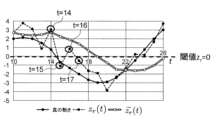
- vibrations caused by errors in the z-axis value in the three-dimensional operation coordinate C may cause it to be determined that the user has performed multiple operations even if the user intended only one operation. This causes so-called chattering. For example, if the value of the z-axis at the three-dimensional operation coordinate C changes as shown in the graph shown in FIG. It is determined that your finger has passed by mistake. In order to prevent such a situation, the fall of the z-axis value in the three-dimensional operation coordinate C, in other words, the threshold value from the positive side to the negative side, and the rise, in other words, the threshold value from the negative side to the positive side. It is effective to change.
- the threshold value for detecting that the instruction input object has passed through the aerial reception range R and the threshold value for detecting that the instruction input object has passed through the aerial reception range R, and the threshold value for detecting that the instruction input object has returned to the side before passing through the plane after the instruction input object has passed through the aerial reception range R.
- the threshold value for detecting this may be set to be different.
- the graph shown in FIG. 13 specifically shows this.
- the transition of z(t) which is the value of the z-axis at the three-dimensional operation coordinate C, is the same as the graph shown in FIG. 12, but the falling threshold is "0" and the rising threshold is “ 1” is set.
- Embodiment 2 As shown in FIG. 1, like the non-contact input device 100 according to the first embodiment, the non-contact input device 200 according to the second embodiment also has a mechanism installed inside the housing 101. An aerial image 102 is projected in the air. Then, the non-contact input device 200 detects an operation on the buttons 103a, 103b, and 103c included in the aerial image 102 using the image capturing device 104, and notifies the user of the operation using the speaker 105. .
- the non-contact input device 200 includes a three-dimensional coordinate acquisition section 110, a smoothing processing section 113, an aerial image projection section 214, and an aerial acceptance range passage determination section. 215, a feedback section 116, and an output section 117.
- the three-dimensional coordinate acquisition section 110, smoothing processing section 113, feedback section 116, and output section 117 of the non-contact input device 200 in the second embodiment are the same as the three-dimensional coordinate acquisition section 110 of the non-contact input device 100 in the first embodiment. , the smoothing processing section 113, the feedback section 116, and the output section 117.
- the aerial image projection unit 214 provides the aerial reception range R to the aerial reception range passage determination unit 215, and the aerial reception range passage determination unit 215 receives the three-dimensional operation coordinate detection unit 112 from the three-dimensional operation coordinate detection unit 112. It receives the coordinate C, receives the smoothed three-dimensional operation coordinate SC from the smoothing processing section 113, gives the passage determination result P to the feedback section 116, and outputs the passage coordinate CSC to the output section 117.
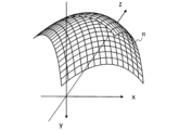
- the aerial image projection unit 214 projects a curved surface that is a part of a spherical surface as shown in FIG. 14 into the air. It is assumed that the aerial reception range R in the second embodiment coincides with the curved surface. Note that the aerial reception range R shown in FIG. 14 is displayed with a mesh to make it easier to visually grasp the shape.
- the aerial reception range R in the shape of a curved surface which is a part of a spherical surface, is superior to a flat surface as a user interface.
- the user generally operates the non-contact input device 200 near the center of the aerial reception range R, but if the aerial reception range R is a flat surface as in the first embodiment, The distance from the user to the aerial reception range differs greatly between the center of the reception range R and the ends thereof.
- the aerial reception range R shown in FIG. 14 is exaggerated to emphasize the difference from Embodiment 1, and in practice, an aerial reception range R with a slightly higher curvature, in other words, a flat one, is useful. It is.
- the aerial reception range R is limited by the limits of g x ( x, y, z) and g y (x, y, z) when expressed as x, y, z) and g y (x, y, z). do.
- FIG. 15 is a diagram of the vicinity of the aerial reception range R cut along a plane perpendicular to the y-axis.
- the length of the arc AB is d ⁇ .
- the hypotenuse of ⁇ is d and the opposite side is x ⁇ xr, the following equation (8) holds true.
- the coordinates in the aerial reception range R are determined, and the limits of the coordinate area are
- the aerial acceptance range passage determination unit 215 in the second embodiment inputs instructions from the three-dimensional operation coordinates C and the aerial acceptance range R indicated by the aerial acceptance range information from the aerial image projection unit 114. It is determined whether a finger, which is an example of an object, has passed through the aerial reception range R. Then, the aerial acceptance range passage determination unit 215 provides the feedback unit 116 with a passage determination result P indicating the determination result.
- f(x, y, z) changes from positive to negative or from negative to positive
- it always passes through the aerial reception range R, which is set as f(x, y, z) 0. That will happen. Therefore, by checking the value of f(x, y, z), the aerial acceptance range passage determining unit 215 can determine whether the instruction input object has passed through the aerial acceptance range.
- the aerial reception range R is a part of a spherical surface as shown in FIG.
- the aerial acceptance range passage determination unit 215 uses the smoothed three-dimensional operation coordinates SC to identify passage coordinates that are the coordinates at which the instruction input object has passed through the aerial acceptance range R. Specifically, the aerial acceptance range passage determining unit 215 determines which coordinates in the aerial acceptance range R the finger, which is the instruction input object, has passed using the smoothed three-dimensional operation coordinates SC from the smoothing processing unit 113. Specify the passing coordinate CSC shown.
- the passing coordinate CSC is the x-axis in the smoothed three-dimensional operating coordinate SC at the time t when it is determined that the finger, which is an example of the instruction input object, has passed through the aerial acceptance range R from the three-dimensional operating coordinate C. , the y-axis value, and the z-axis value.
- the aerial reception range passage determination unit 215 determines that the instruction input object has passed through the aerial reception range R. In other words, the instruction input object is input to the aerial reception range R. It is determined that this has taken place.
- FIG. 16 is a flowchart showing the operation of determining whether an instruction input object has passed through one aerial reception range R in the second embodiment.
- the aerial acceptance range passage determining unit 215 determines that the value of the function f at time t-1, f(x(t-1), y(t-1), z(t-1)), is negative, and It is determined whether f(x(t), y(t), z(t)), which is the value of function f at time t, is positive or 0 (S30).
- the aerial acceptance range passage determination unit 215 smoothes the x-coordinate value, the y-coordinate value, and the z-coordinate value at time t in the smoothed three-dimensional operation coordinate SC. It is determined whether the passing coordinate CSC, which is the converted value, satisfies the following equations (13) and (14) (S31). (13) (14)
- step S31 If both equations (13) and (14) are satisfied (Yes in S31), the process proceeds to step S32, and if at least one of equations (13) and (14) is not satisfied (S31 If the answer is No), the process proceeds to step S33.
- step S32 the aerial reception range passage determining unit 315 determines that the instruction input object has passed through one target aerial reception range R.
- the x-coordinate and y-coordinate of the passing coordinates are as shown in equation (15) below.
- step S33 the aerial reception range passage determination unit 315 determines that the instruction input object has not passed through one target aerial reception range R.
- the aerial reception range passage determination unit 315 can specify which aerial reception range R. It is possible to specify whether the input object has passed.
- the aerial reception range R is a part of the spherical surface, but the function f(x, y, z) indicating the aerial reception range R can be expressed as an arbitrary aerial reception range coordinate system x , y, and z as parametric variables.
- the aerial reception range R has the center as (x c , y c , z c ), and the lengths in the x, y, and z axis directions are x l , y l ,
- the function f may be set as shown in equation (16) below.
- the function f may be expressed as in equation (17) below.
- x r and y r are fixed points
- z r is the base containing the fixed straight line of the corresponding parabola.
- f(x, y, z) may be a polynomial such as a hyperboloid, or may have a shape expressed by a trigonometric polynomial, and the differentiability is not a concern, so x, It may be in the form of a table whose parameter is the value of y, z or a polynomial that is a combination thereof, or it may be a so-called polygon, which is a combination of two or more planes. Note that the aforementioned rectangular parallelepiped is an example of a polygon.
- the non-contact input device 300 As shown in FIG. 1, like the non-contact input device 100 according to the first embodiment, the non-contact input device 300 according to the third embodiment also has a mechanism installed inside the housing 101. An aerial image 102 is projected in the air. Then, the non-contact input device 300 detects an operation on the buttons 103a, 103b, and 103c included in the aerial image 102 using the image capturing device 104, and notifies the user that the operation has been performed through the speaker 105. .
- the non-contact input device 300 includes a three-dimensional coordinate acquisition section 110, a smoothing processing section 113, an aerial image projection section 114, and an aerial acceptance range passage determination section. 315, a feedback section 116, and an output section 117.
- the three-dimensional coordinate acquisition section 110, smoothing processing section 113, aerial image projection section 114, feedback section 116, and output section 117 of the non-contact input device 300 in the third embodiment are the same as those of the non-contact input device 100 in the first embodiment. It is the same as the three-dimensional coordinate acquisition section 110, the smoothing processing section 113, the aerial image projection section 114, the feedback section 116, and the output section 117.
- the aerial acceptance range passage determination unit 315 in the third embodiment receives the three-dimensional operation coordinate C from the three-dimensional operation coordinate detection unit 112, the aerial acceptance range R from the aerial image projection unit 114, and the smoothed three-dimensional information from the smoothing processing unit 113.
- the original operation coordinates SC are each received, the passage determination result P is given to the feedback unit 116, and the passage coordinate CSC is specified.
- the aerial acceptance range passage determining unit 315 determines an example of the instruction input object from the three-dimensional operation coordinates C and the aerial acceptance range R indicated by the aerial acceptance range information from the aerial image projection unit 114. It is determined whether a certain finger has passed through the aerial acceptance range R or not. Then, the aerial acceptance range passage determination unit 315 provides the feedback unit 116 with a passage determination result P indicating the determination result.
- the aerial acceptance range passage determining unit 315 in the third embodiment indicates which coordinates in the aerial acceptance range R the finger, which is the instruction input object, has passed using the smoothed three-dimensional operation coordinates SC from the smoothing processing unit 113. Specify the passing coordinate CSC.
- the passage coordinate CSC is determined from the three-dimensional operation coordinate C and the aerial acceptance range R indicated by the aerial acceptance range information from the aerial image projection unit 114.
- time t+D which is delayed by a predetermined delay time D from time t when it is determined that the passage has passed, the x-axis value and y-axis value obtained by the above equation (3) are calculated as the passage coordinate at that time t. Identify as CSC.
- the aerial reception range passage determination unit 315 determines the aerial reception range indicated by the specified passage coordinate CSC and the aerial reception range information from the aerial image projection unit 114. From R, it is determined which aerial reception range R among the plurality of aerial reception ranges R the finger, which is the instruction input object, has passed through.
- the aerial acceptance range passage determining unit 315 specifies the value of the first axis extending in the direction intersecting the aerial acceptance range R from the three-dimensional operation coordinate C, out of the three axes, Using the specified value, the time when the instruction input object passes through the aerial reception range R is specified.
- the aerial acceptance range passage judgment unit 215 calculates the values of the second and third axes, which are obtained by excluding the first axis from the three axes, at a delay time that is later than the specified time as a passage coordinate CSC. is determined from the smoothed three-dimensional operation coordinates SC. Then, when the passing coordinate CSC is within the aerial acceptance range R, the aerial acceptance range passage determining unit 215 determines that an input has been made to the aerial acceptance range R.
- the delay time may be the time obtained by adding a time equal to or less than the delay time, which is the time for the smoothing processing unit 113 to calculate the smoothed three-dimensional operation coordinates, to the specified time.
- the delay time may be the time obtained by adding a time equal to or less than the delay time, which is the time for the smoothing processing unit 113 to calculate the smoothed three-dimensional operation coordinates, to the specified time.
- the smoothing processing unit 113 performs smoothing using a linear phase filter
- the value of the group delay of the linear phase filter may be used as the delay time.
- the feedback unit 116 outputs an output at the time when the passage determination result P becomes true, as in the first embodiment. This allows the user to receive prompt response to the operation.
- FIGS. 18(A) to 18(C) are graphs for explaining in detail the operation of the aerial acceptance range passage determination unit 315.
- the graphs in FIGS. 18(A) to (C) are similar to the graphs in FIGS. 8(A) to (C).
- the delay time D is assumed to be "3" corresponding to the time for three frames.
- the third embodiment is effective when it is desired to use a value closer to the true value as the value of the passing coordinate CSC.
- the user feels that the responsiveness is good.
- the passing coordinate CSC is specified at a time when the delay time D is taken into consideration, if processing using the passing coordinate CSC is required, the actual processing time will not be shortened.
- a moving average filter is used here as a smoothing filter, for example, when a smoothing method with nonlinear phase characteristics such as an IIR filter is used, the delay time differs for each frequency component. It is difficult to determine the delay time D.
- FIGS. 19A and 19B are schematic diagrams showing the configuration of a two-stage cascade type IIR filter.
- FIG. 20 is a graph showing the group delay characteristics of the two-stage cascade type IIR filter shown in FIGS. 19(A) and 19(B).
- FIG. 20 shows a case where the frame rate of the image capturing device 104 is 30 frames per second.
- the delay time D is set to a value that is greater than or equal to the minimum value of the group delay characteristic and less than or equal to the maximum value, here, that is greater than or equal to 0 samples and less than or equal to 10 samples.
- the delay time D is set to a time corresponding to seven samples based on the group delay of the DC component. Note that it is 30 Hz because it is derived from the sampling rate of the three-dimensional operation coordinate C.
- the delay time D should be smaller than the flat group delay.
- a filter with linear phase characteristics such as a moving average filter or an FIR filter designed using a window function method
- the delay time D should be smaller than the flat group delay.
- values for example, in the case of a 7-tap moving average filter, it is advantageous to set the delay to "2" or "1", which is smaller than the group delay of 3 samples. This is effective when it is necessary to balance both the essential processing time and the accuracy of the passing coordinate CSC. Note that when the delay time D is "0", the operation of the third embodiment matches that of the first embodiment.
- Embodiment 4 As shown in FIG. 1, similarly to the non-contact input device 100 according to the first embodiment, the non-contact input device 400 according to the fourth embodiment also uses a mechanism installed inside the housing 101. An aerial image 102 is projected in the air. Then, the non-contact input device 400 detects an operation on the buttons 103a, 103b, and 103c included in the aerial image 102 using the image capturing device 104, and notifies the user that the operation has been performed through the speaker 105. .
- FIG. 21 is a block diagram schematically showing the configuration of a non-contact input device 400 in the fourth embodiment.
- the non-contact input device 400 in the fourth embodiment includes a three-dimensional coordinate acquisition section 110, a smoothing processing section 113, an aerial image projection section 114, an aerial acceptance range passage determination section 415, a feedback section 116, and an output section. 117, and a low delay smoothing processing unit 418.
- the three-dimensional coordinate acquisition section 110, smoothing processing section 113, aerial image projection section 114, feedback section 116, and output section 117 of the non-contact input device 400 in the fourth embodiment are the same as those of the non-contact input device 100 in the first embodiment. It is the same as the three-dimensional coordinate acquisition section 110, the smoothing processing section 113, the aerial image projection section 114, the feedback section 116, and the output section 117.
- the low-delay smoothing processing section 418 receives the three-dimensional operation coordinate C from the three-dimensional operation coordinate detection section 112, and smoothes the three-dimensional operation coordinate C in the time direction by smoothing processing with low delay from the smoothing processing section 113. , and provides the result to the aerial acceptance range passage determination unit 415 as a low-delay smoothed three-dimensional operation coordinate LSC.
- the low-delay smoothing processing unit 418 calculates the smoothed three-dimensional operating coordinates C in advance with a delay time shorter than the time required for the smoothing processing unit 113 to calculate the smoothed three-dimensional operating coordinates SC.
- a low-delay smoothed three-dimensional operating coordinate LSC is calculated by performing smoothing using a second number of three-dimensional operating coordinates that is a predetermined number of two or more.
- the smoothing processing unit 113 performs smoothing using a 7-tap moving average filter as described above, for example, the low delay smoothing processing unit 418 performs smoothing using a 7-tap moving average filter as shown in equation (18) below.
- a low-delay smoothed three-dimensional operation coordinate LSC is calculated by performing smoothing with a moving average filter of taps.
- the aerial reception range passage determination unit 415 in the fourth embodiment receives the low-delay smoothed three-dimensional operation coordinates LSC from the low-delay smoothing processing unit 418, the aerial reception range R from the aerial image projection unit 114, and the smoothing processing unit 113.
- the smoothed three-dimensional operation coordinates SC are received from each of the three-dimensional operation coordinates SC, and the passage determination result P is given to the feedback unit 116, which specifies the passage coordinate CSC.
- the aerial acceptance range passage determination unit 415 determines whether a finger, which is an example of an instruction input object, is based on the low-delay smoothed three-dimensional operation coordinate LSC and the aerial acceptance range R indicated by the aerial acceptance range information from the aerial image projection unit 114. It is determined whether the air reception range R has been passed. Then, the aerial acceptance range passage determination unit 415 provides the feedback unit 116 with a passage determination result P indicating the determination result.
- the aerial acceptance range passing judgment unit 415 determines which coordinates within the aerial acceptance range R the finger, which is the instruction input object, is pointing to, based on the smoothed three-dimensional operation coordinates SC from the smoothing processing unit 113.
- the passage coordinate CSC indicating whether the vehicle has passed is specified.
- the passage coordinate CSC is determined from the three-dimensional operation coordinate C and the aerial acceptance range R indicated by the aerial acceptance range information from the aerial image projection unit 114.
- the x-axis value and the y-axis value are determined by the above equation (3).
- the aerial acceptance range passage determining unit 415 determines the specified passage coordinate CSC and the aerial image projection unit 114 from the aerial image projection unit 114. Based on the aerial acceptance range R indicated by the acceptance range information, it is determined which aerial acceptance range R among the plurality of aerial acceptance ranges R the finger, which is the instruction input object, has passed through.
- the aerial acceptance range passage determining unit 415 calculates the value of the first axis extending in the direction intersecting the aerial acceptance range R out of the three axes by using the low delay smoothed three-dimensional operation coordinate LSC.
- the specified value is used to specify the time at which the instruction input object passes through the aerial reception range R.
- the aerial acceptance range passage determination unit 415 uses the values of the second and third axes obtained by excluding the first axis from the three axes at the specified time as passage coordinates CSC and smoothed three-dimensional operation coordinates SC. Specify from Then, when the passing coordinate CSC is within the aerial acceptance range R, the aerial acceptance range passage determining unit 415 determines that an input has been made to the aerial acceptance range R.
- the low-delay smoothing processing unit 418 can also perform smoothing using a method other than the 3-tap moving average filter.
- a method other than the 3-tap moving average filter For example, it is possible to use an FIR filter or IIR filter using a window function method or the like.
- a part or all of the three-dimensional operation coordinate detection unit 112, smoothing processing unit 113, aerial acceptance range passing determination unit 415, feedback unit 116, and low delay smoothing processing unit 418 described above may be configured, for example, in FIG. As shown in A), it can be configured by a memory 10 and a processor 11 that executes a program stored in the memory 10.
- a program may be provided through a network, or may be provided recorded on a recording medium. That is, such a program may be provided as a program product, for example.
- the three-dimensional operation coordinate detection unit 112, smoothing processing unit 113, aerial acceptance range passage determination unit 415, feedback unit 116, and low delay smoothing processing unit 418 may be configured as shown in FIG. 6(B), for example. As shown, it may also consist of a processing circuit 12. As described above, the three-dimensional operation coordinate detection section 112, the smoothing processing section 113, the aerial acceptance range passage determination section 415, the feedback section 116, and the low-delay smoothing processing section 418 can be realized by a processing circuit network.
- FIG. 22 is a flowchart showing the operation of determining whether an instruction input object has passed through one aerial reception range R in the fourth embodiment.
- the aerial reception range R is (
- ⁇ y max , z 0) as shown in FIG.
- steps that perform the same processing as the steps in the flowchart shown in FIG. 7 are given the same reference numerals as in FIG.
- the aerial acceptance range passage determination unit 415 determines that the value of the z coordinate at time t-1 in the low delay smoothed three-dimensional operating coordinates LSC is positive or 0, and that It is determined whether the value of the z coordinate at time t is negative (S40). If the condition in step S40 is satisfied (Yes in S40), the process proceeds to step S11, and if the condition in step S40 is not satisfied (No in S40), the process proceeds to step S13. Note that the processing in steps S11 to S13 in FIG. 22 is similar to the processing in steps S11 to S13 in FIG.
- the fall is determined using the value of the z-axis of the three-dimensional operation coordinate C that has not been smoothed, but in the fourth embodiment, a low delay that is not very long is used. Using the value of the z-axis of the smoothed three-dimensional operating coordinate LSC, its falling edge is determined.
- FIGS. 23A to 23C show the above operation in detail.
- FIGS. 23(A) to 23(C) are graphs for explaining the operation of the aerial acceptance range passage determination unit 415.
- FIG. 23(A) shows the x-axis value of the actual finger movement, the x-axis value of the three-dimensional operation coordinate C, and the x-axis value of the smoothed three-dimensional operation coordinate SC in the aerial reception range coordinate system. It is a graph showing a time series of. The horizontal axis of FIG. 23(A) indicates time, and the vertical axis indicates the value of the x-axis.
- FIG. 23(B) shows the y-axis value of the actual finger movement, the y-axis value of the three-dimensional operation coordinate C, and the y-axis value of the smoothed three-dimensional operation coordinate SC in the aerial reception range coordinate system. It is a graph showing a time series of. The horizontal axis of FIG. 23(B) indicates time, and the vertical axis indicates the value of the y-axis.
- FIG. 23(C) shows the z-axis value of the actual finger movement, the z-axis value of the three-dimensional operation coordinate C, and the z-axis of the low-delay smoothed three-dimensional operation coordinate LSC in the aerial reception range coordinate system. It is a graph showing a time series with the value of. The horizontal axis of FIG. 23(C) indicates time, and the vertical axis indicates the value of the z-axis.
- the solid line is the true value as the actual finger coordinate
- the broken line is the value of the measured three-dimensional operation coordinate C.
- the double line is the value of the smoothed three-dimensional operating coordinate SC obtained by smoothing the value of the three-dimensional operating coordinate C.
- the double line is the value of the low-delay smoothed three-dimensional operating coordinate LSC obtained by smoothing the value of the three-dimensional operating coordinate C with low delay.
- the z-axis value of the smoothed 3D operation coordinate SC is delayed by 3 frames than the z-axis value of the 3D operation coordinate C. This delay is small by comparison. Therefore, in the third embodiment as well, the passage determination result P can be outputted relatively quickly, and feedback to the user can also be outputted relatively quickly.
- the smoothed three-dimensional operation coordinates SC can be used as the coordinates passing through the aerial reception range, values that have been smoothed more strongly can be used. Since the smoothed three-dimensional operation coordinates SC has a relatively large delay, there is a problem in that the coordinates of the designated input object at a past time are output.
- the x-axis and y-axis values of the smoothed three-dimensional operation coordinate SC are almost constant, so there is no possibility that the magnitude of this delay will become a problem. considered to be low.
- the smoothed three-dimensional operating coordinates SC are used to detect the coordinates through which the instruction input object passes. Vibration due to time-varying noise can be removed.
- Embodiments 1 to 4 when determining whether or not the instruction input object has passed through a plane that includes a range that accepts operations, a value that has not been smoothed or a value that has been smoothed with low delay is used. By using the calculated values, it is possible to achieve both system responsiveness and detection position accuracy.
- the aerial acceptance range passage determination units 115 to 415 based on the z-axis value of the three-dimensional operation coordinate C or the low-delay smoothed three-dimensional operation coordinate LSC, although the passage determination result P is provided to the feedback unit 116, the first to fourth embodiments are not limited to such an example.
- the aerial acceptance range passage determination units 115 to 415 may provide the passage determination result P to the feedback unit 116 when the passage coordinate CSC is within the corresponding range.
- the aerial reception range passage determination units 115 to 415 determine whether the three-dimensional operating coordinate C or the low-delay smoothed three-dimensional operating coordinate LSC falls at the time when the z-axis value of the three-dimensional operating coordinate C or the low-delay smoothed three-dimensional operating coordinate LSC falls.
- the passage determination result P may be given to the feedback unit 116.
- the aerial reception range R is a plane for the sake of simplicity of explanation, but similarly to the second embodiment, the aerial reception range R is a spherical surface, a paraboloid, a It may be a part of the shape expressed by a polynomial such as a hyperboloid or a trigonometric polynomial, and the differentiability is not a concern, so the values of x, y, z or a polynomial combining them can be used as the parameter.
- the shape may be a table-like shape, or a combination of two or more planes (for example, a rectangular parallelepiped or a polyhedron), a so-called polygon.
- the aerial acceptance range passage determination unit 415 preliminarily determines that the output of a function that receives the low-delay smoothed three-dimensional operation coordinate LSC as an input becomes a predetermined value in the aerial acceptance range R. It is determined whether the instruction input object has passed through the aerial reception range R using a predetermined function.
- the aerial acceptance range passage determination unit 415 sequentially inputs a plurality of low-delay smoothed three-dimensional operation coordinates LSC to the function, and if the output of the function becomes larger than or smaller than the value, In this case, it is determined whether the instruction input object has passed through the aerial reception range R or not.
Landscapes
- Engineering & Computer Science (AREA)
- General Engineering & Computer Science (AREA)
- Theoretical Computer Science (AREA)
- Human Computer Interaction (AREA)
- Physics & Mathematics (AREA)
- General Physics & Mathematics (AREA)
- Multimedia (AREA)
- Position Input By Displaying (AREA)
Abstract
Description
図1は、実施の形態1に係る非接触入力装置100の外観を示す斜視図である。
非接触入力装置100は、筐体101の内部に搭載された機構により、予め定められた空間に空中画像102を投影する。空中画像102を投影する機構に関しては、公知の技術が使用されればよいため、その詳細な説明は省略する。公知の技術としては、例えば、筐体101内にディスプレイが搭載され、再帰性反射材と、ハーフミラーとを用いて、空間にディスプレイから出る光を再結像させることで、空中画像102を投影することができる。なお、この投影を行う機構に関しては、別の手段が用いられてもよい。
なお、各々のボタン103a、103b、103cを区別する必要がない場合には、ボタン103a、103b、103cの一つをボタン103という。
非接触入力装置100は、三次元座標取得部110と、平滑化処理部113と、空中画像投影部114と、空中受付範囲通過判断部115と、フィードバック部116と、出力部117とを備える。
三次元座標取得部110は、三次元画像撮像部111と、三次元操作座標検出部112とを備える。
具体的には、三次元画像撮像部111は、後述する空中画像投影部114が投影する空中画像が含まれるように、予め定められた空間の三次元の画像である三次元画像IMを出力する。
ここでは、三次元操作座標検出部112は、指示入力物体の三次元操作座標Cを順次検出することで、時刻の異なる複数の三次元操作座標Cを検出する。
図3(A)は、三次元画像IMを示す。ここでの三次元画像IMは、横軸X及び縦軸Yで示され、ピクセルの濃淡が画像撮像機104からの距離を示す距離画像であるものとする。ここで、三次元画像IMでは、距離は、輝度が大きいピクセルほど画像撮像機104から近いことを示す。
三次元操作座標検出部112は、三次元画像IMに対して二値化を施すことで、二値化三次元画像IM#1を生成する。二値化は、指等の指示入力物体の点と、それ以外の点とを区別するために行われる。そのため、そのような区別を適切に行うことができるように、閾値が決定されているものとする。例えば、図1に示されているように、画像撮像機104が下向きに設置される場合、閾値は、ボタン103a、103b、103cのそれぞれに対応する空中受付範囲のうちの最遠端より遠く、地面より近い値に設定されるのが望ましい。
図3(C)は、ノイズ除去三次元画像IM#2を示す概略図である。
距離画像には一般に比較的大きなノイズが載る。このため、図3(B)に示されている二値化三次元画像IM#1にも細かいノイズが多数載っている。これに対して、閉領域として検出する最低面積をある程度大きくすることで、三次元操作座標検出部112は、図3(C)に示されているノイズ除去三次元画像IM#2のように、ノイズを除去している。なお、ノイズ除去の方法としては、他にもメジアンフィルタを用いる方法、又は、クロージング後にオープニングを行う方法等、さまざまな方法が適用可能である。

なお、この変換は、空中受付範囲Rの数だけ行われるが、図5においては、説明を簡単にするため、一つの空中受付範囲R1だけを表している。

例えば、平滑化処理部113は、三次元操作座標Cを時間方向に平滑化し、その結果を平滑化三次元操作座標SCとして空中受付範囲通過判断部115に与える。本実施の形態での平滑化方法は、7タップの移動平均による平滑化とする。時刻tにおける(x,y,z)をx(t)、y(t)及びz(t)とし、平滑化処理部113は、下記の(3)式により平滑化三次元操作座標SCを算出する。

ここで、空中画像投影部114は、空中受付範囲座標系で空中受付範囲Rを示す空中受付範囲情報を空中受付範囲通過判断部115に与える。
実施の形態1では、空中受付範囲Rがf(x、y、z)=zとなる平面であるものとして説明する。
具体的には、空中受付範囲通過判断部115は、平滑化処理部113からの平滑化三次元操作座標SCにより、指示入力物体である指が、空中受付範囲Rのどの座標を通過したかを示す通過座標CSCを特定する。
ここでは、出力部117は、ユーザへのフィードバックを出力する。例えば、出力部117が、図1に示されているスピーカ105である場合には、出力部117は、操作受付音を出力する。
なお、出力部117は、音を出力するスピーカ105に限定されるものではなく、ディスプレイ等の他の手段であってもよい。また、出力部117は、指示入力物体に触感を与える超音波を出力してもよい。
以上のように、三次元操作座標検出部112、平滑化処理部113、空中受付範囲通過判断部115及びフィードバック部116は、処理回路網により実現することができる。
ここでは、空中受付範囲Rが、図5に示されているように、空中受付範囲R1(|x|<xmax,|y|<ymax,z=0)となっているものとする。
なお、フレームレートが30フレーム毎秒の場合、時刻t-1と、時刻tとの時間差は、一フレーム分の時間差である1/30秒である。


一方、ステップS13では、空中受付範囲通過判断部115は、指示入力物体が対象となる一つの空中受付範囲Rを通過しなかったと判断する。
そして、ステップS11では、t=15における平滑化三次元操作座標SCのx軸の値及びy軸の値が用いられて判断が行われる。
さらに、このボタン103上のどの座標を通ったかを示す、通過座標CSCも、平滑化三次元操作座標SCの値が適用される。
通過座標CSCは、例えば、下記の(6)式のように、前時刻t=14との加重平均であってもよい。


これにより、時刻t=15までは、閾値は「0」であり、立ち下がりが観測された時刻t=15よりも後は、閾値は「1」に代わる。これにより、図12で存在した時刻t=17におけるチャタリングは解消されている。この閾値「1」は、立ち上がりが観測される時刻t=25で再度「0」に戻る。
図1に示されているように、実施の形態2に係る非接触入力装置200も、実施の形態1に係る非接触入力装置100と同様に、筐体101の内部に搭載された機構により、空中に空中画像102を投影する。
そして、非接触入力装置200は、空中画像102に含まれているボタン103a、103b、103cへの操作を、画像撮像機104を用いて検出し、操作が行われたことをスピーカ105で通知する。
但し、実施の形態2においては、空中画像投影部214が空中受付範囲Rを空中受付範囲通過判断部215に与え、空中受付範囲通過判断部215は、三次元操作座標検出部112から三次元操作座標Cを受け取り、平滑化処理部113から平滑化三次元操作座標SCを受け取り、通過判定結果Pをフィードバック部116に与え、通過座標CSCを出力部117に出力する。
ここで、弧の長さの式から、弧ABの長さはdθである。ただし、θは斜辺がd、対辺がx-xrであることから、下記の(8)式が成立する。





実施の形態2では、空中受付範囲Rが、図14に示されているような、球面の一部である。
具体的には、空中受付範囲通過判断部215は、平滑化処理部113からの平滑化三次元操作座標SCにより、指示入力物体である指が、空中受付範囲Rのどの座標を通過したかを示す通過座標CSCを特定する。



一方、ステップS33では、空中受付範囲通過判断部315は、指示入力物体が対象となる一つの空中受付範囲Rを通過しなかったと判断する。


ここで、xr及びyrは、定点であり、zrは、対応する放物線の定直線を含む底面である。
図1に示されているように、実施の形態3に係る非接触入力装置300も、実施の形態1に係る非接触入力装置100と同様に、筐体101の内部に搭載された機構により、空中に空中画像102を投影する。
そして、非接触入力装置300は、空中画像102に含まれているボタン103a、103b、103cへの操作を、画像撮像機104を用いて検出し、操作が行われたことをスピーカ105で通知する。
例えば、平滑化処理部113が線形位相フィルタを用いて平滑化を行う場合には、遅延時間として、その線形位相フィルタの群遅延の値が用いられればよい。
図18(A)~(C)のグラフは、図8(A)~(C)のグラフと同様である。
ここで、遅延時間Dは、3フレーム分の時間に対応する「3」とする。
また、図20は、図19(A)及び(B)に示されている2段カスケード型IIRフィルタの群遅延特性を示すグラフである。
ここでは、図20は、画像撮像機104のフレームレートが30フレーム毎秒の場合である。
なお、三次元操作座標Cのサンプリングレートに由来するため、30Hzになる。
なお、遅延時間Dが「0」のとき、実施の形態3の動作は実施の形態1と一致する。
図1に示されているように、実施の形態4に係る非接触入力装置400も、実施の形態1に係る非接触入力装置100と同様に、筐体101の内部に搭載された機構により、空中に空中画像102を投影する。
そして、非接触入力装置400は、空中画像102に含まれているボタン103a、103b、103cへの操作を、画像撮像機104を用いて検出し、操作が行われたことをスピーカ105で通知する。
実施の形態4における非接触入力装置400は、三次元座標取得部110と、平滑化処理部113と、空中画像投影部114と、空中受付範囲通過判断部415と、フィードバック部116と、出力部117と、低遅延平滑化処理部418とを備える。
言い換えると、低遅延平滑化処理部418は、平滑化処理部113が平滑化三次元操作座標SCを算出するための時間よりも短い遅延時間で、複数の三次元操作座標Cに含まれる、予め定められた二以上の数である第二の数の三次元操作座標を用いて平滑化を行うことで、低遅延平滑化三次元操作座標LSCを算出する。

以上のように、三次元操作座標検出部112、平滑化処理部113、空中受付範囲通過判断部415、フィードバック部116及び低遅延平滑化処理部418は、処理回路網により実現することができる。
図22は、実施の形態4において、指示入力物体が一つの空中受付範囲Rを通過したかを判断する動作を示すフローチャートである。
ここでは、空中受付範囲Rが、図5に示されているように、(|x|<xmax,|y|<ymax,z=0)であるものとする。
また、図22に示されているフローチャートのステップの内、図7に示されているフローチャートのステップと同じ処理を行うステップについては、図7と同じ符号を付す。
なお、図22のステップS11~S13の処理については、図7のステップS11~S13の処理と同様である。
図23(A)~(C)は、空中受付範囲通過判断部415の動作を説明するためのグラフである。
図23(A)及び(B)では、二重線は、三次元操作座標Cの値を平滑化した平滑化三次元操作座標SCの値である。一方、図23(C)では、二重線は、三次元操作座標Cの値を低遅延で平滑化した低遅延平滑化三次元操作座標LSCの値である。
そこで、実施の形態1~4では、指示入力物体が、操作を受け付ける範囲を含む平面を通過したか否かを判断する際には、平滑化が行われていない値又は低遅延の平滑化が行われた値を用いることにより、システムの応答性と、検出位置の精度とを両立することができる。
Claims (21)
- 指示を入力する物体である指示入力物体の、予め定められた空間における三軸の座標である三次元操作座標を順次検出することで、複数の三次元操作座標を検出する三次元操作座標検出部と、
前記複数の三次元操作座標に含まれる、予め定められた二以上の数である第一の数の三次元操作座標を用いて平滑化を行うことで、平滑化三次元操作座標を算出する平滑化処理部と、
前記平滑化三次元操作座標を用いて、前記空間において予め定められた範囲である空中受付範囲を前記指示入力物体が通過した座標である通過座標を特定する通過判断部と、を備えること
を特徴とする非接触入力装置。 - 前記通過判断部は、前記複数の三次元操作座標を用いて、前記空間において予め定められた範囲である空中受付範囲を前記指示入力物体が通過したか否かを判断すること
を特徴とする請求項1に記載の非接触入力装置。 - 前記通過判断部は、前記三次元操作座標を入力とする関数の出力が、前記空中受付範囲において予め定められた値となるように予め定められた前記関数を用いて、前記空中受付範囲を前記指示入力物体が通過したか否かを判断すること
を特徴とする請求項2に記載の非接触入力装置。 - 前記通過判断部は、前記複数の三次元操作座標を、順次、前記関数に入力し、前記関数の出力が前記値よりも大きくなった場合又は小さくなった場合に、前記空中受付範囲を前記指示入力物体が通過したか否かを判断すること
を特徴とする請求項3に記載の非接触入力装置。 - 前記平滑化処理部が前記平滑化三次元操作座標を算出するための時間よりも短い遅延時間で、前記複数の三次元操作座標に含まれる、予め定められた二以上の数である第二の数の三次元操作座標を用いて平滑化を行うことで、低遅延平滑化三次元操作座標を算出する低遅延平滑化処理部をさらに備え、
前記通過判断部は、前記低遅延平滑化三次元操作座標を用いて、前記空間において予め定められた範囲である空中受付範囲を前記指示入力物体が通過したか否かを判断すること
を特徴とする請求項1に記載の非接触入力装置。 - 前記通過判断部は、前記低遅延平滑化三次元操作座標を入力とする関数の出力が、前記空中受付範囲において予め定められた値となるように予め定められた前記関数を用いて、前記空中受付範囲を前記指示入力物体が通過したか否かを判断すること
を特徴とする請求項5に記載の非接触入力装置。 - 前記通過判断部は、複数の前記低遅延平滑化三次元操作座標を、順次、前記関数に入力し、前記関数の出力が前記値よりも大きくなった場合又は小さくなった場合に、前記空中受付範囲を前記指示入力物体が通過したか否かを判断すること
を特徴とする請求項6に記載の非接触入力装置。 - 前記通過判断部は、前記空中受付範囲を前記指示入力物体が通過した場合には、前記空中受付範囲を前記指示入力物体が通過した時刻を特定し、前記特定された時刻における前記平滑化三次元操作座標を前記通過座標として特定し、前記通過座標が前記空中受付範囲内にある場合に、前記空中受付範囲への入力が行われたと判断すること
を特徴とする請求項2から7の何れか一項に記載の非接触入力装置。 - 前記通過判断部は、前記空中受付範囲を前記指示入力物体が通過した場合には、前記空中受付範囲を前記指示入力物体が通過した時刻を特定し、前記特定された時刻よりも遅い時刻である遅延時刻における前記平滑化三次元操作座標を前記通過座標として特定し、前記通過座標が前記空中受付範囲にある場合に、前記空中受付範囲への入力が行われたと判断すること
を特徴とする請求項2から7の何れか一項に記載の非接触入力装置。 - 前記遅延時刻は、前記平滑化処理部が前記平滑化三次元操作座標を算出するための時間である遅延時間以下の時間を前記特定された時刻に加えた時刻であること
を特徴とする請求項9に記載の非接触入力装置。 - 前記平滑化処理部は、線形位相フィルタを用いて前記平滑化を行い、
前記遅延時間は、前記線形位相フィルタの群遅延の値であること
を特徴とする請求項10に記載の非接触入力装置。 - 前記空中受付範囲を前記指示入力物体が通過した際に、前記非接触入力装置の外部に出力を行う出力部をさらに備えること
を特徴とする請求項2から11の何れか一項に記載の非接触入力装置。 - 前記空中受付範囲を前記指示入力物体が通過した際に、前記非接触入力装置の外部に出力を行う出力部をさらに備え、
前記出力部は、前記出力を、少なくとも前記遅延時刻まで継続すること
を特徴とする請求項9から11の何れか一項に記載の非接触入力装置。 - 前記出力が音であること
を特徴とする請求項12又は13に記載の非接触入力装置。 - 前記出力が触感を与える超音波であること
を特徴とする請求項12又は13に記載の非接触入力装置。 - 前記空中受付範囲を前記指示入力物体が通過したことを検出する閾値と、前記空中受付範囲を前記指示入力物体が通過した後に、前記指示入力物体が前記空中受付範囲を通過する前の側に戻ったことを検出する閾値とが異なっていること
を特徴とする請求項2から15の何れか一項に記載の非接触入力装置。 - 前記空間に、前記空中受付範囲に対応付けられている部分を有する空中画像を投影する空中画像投影部をさらに備えること
を特徴とする請求項2から16の何れか一項に記載の非接触入力装置。 - 前記空中受付範囲が含まれるように、前記空間の三次元画像を出力する三次元画像撮像部をさらに備え、
前記三次元操作座標検出部は、前記三次元画像から前記複数の三次元操作座標を検出すること
を特徴とする請求項2から17の何れか一項に記載の非接触入力装置。 - 前記指示入力物体が指であること
を特徴とする請求項1から18の何れか一項に記載の非接触入力装置。 - 前記指示入力物体が突起物であること
を特徴とする請求項1から18の何れか一項に記載の非接触入力装置。 - 指示を入力する物体である指示入力物体の、予め定められた空間における三軸の座標である三次元操作座標を順次検出することで、複数の三次元操作座標を検出し、
前記複数の三次元操作座標に含まれる、予め定められた二以上の数である第一の数の三次元操作座標を用いて平滑化を行うことで、平滑化三次元操作座標を算出し、
前記平滑化三次元操作座標を用いて、前記空間において予め定められた範囲である空中受付範囲を前記指示入力物体が通過した座標である通過座標を特定すること
を特徴とする非接触入力方法。
Priority Applications (4)
| Application Number | Priority Date | Filing Date | Title |
|---|---|---|---|
| CN202280093738.XA CN118871879A (zh) | 2022-03-24 | 2022-03-24 | 非接触输入装置和非接触输入方法 |
| PCT/JP2022/013860 WO2023181237A1 (ja) | 2022-03-24 | 2022-03-24 | 非接触入力装置及び非接触入力方法 |
| US18/844,983 US20250199646A1 (en) | 2022-03-24 | 2022-03-24 | Contactless input device |
| JP2024509560A JP7618099B2 (ja) | 2022-03-24 | 2022-03-24 | 非接触入力装置及び非接触入力方法 |
Applications Claiming Priority (1)
| Application Number | Priority Date | Filing Date | Title |
|---|---|---|---|
| PCT/JP2022/013860 WO2023181237A1 (ja) | 2022-03-24 | 2022-03-24 | 非接触入力装置及び非接触入力方法 |
Publications (1)
| Publication Number | Publication Date |
|---|---|
| WO2023181237A1 true WO2023181237A1 (ja) | 2023-09-28 |
Family
ID=88100531
Family Applications (1)
| Application Number | Title | Priority Date | Filing Date |
|---|---|---|---|
| PCT/JP2022/013860 Ceased WO2023181237A1 (ja) | 2022-03-24 | 2022-03-24 | 非接触入力装置及び非接触入力方法 |
Country Status (4)
| Country | Link |
|---|---|
| US (1) | US20250199646A1 (ja) |
| JP (1) | JP7618099B2 (ja) |
| CN (1) | CN118871879A (ja) |
| WO (1) | WO2023181237A1 (ja) |
Citations (3)
| Publication number | Priority date | Publication date | Assignee | Title |
|---|---|---|---|---|
| JP2014219938A (ja) * | 2013-05-10 | 2014-11-20 | 株式会社ゲッシュ | 入力支援装置、入力支援方法、および、プログラム |
| JP2018518784A (ja) * | 2015-05-15 | 2018-07-12 | アシーア インコーポレイテッドAtheer, Inc. | 面限定制御用に自由空間入力を適用する方法および装置 |
| US10275098B1 (en) * | 2015-07-12 | 2019-04-30 | sigmund lindsay clements | Laser mid-air hologram touch input buttons for a device |
Family Cites Families (2)
| Publication number | Priority date | Publication date | Assignee | Title |
|---|---|---|---|---|
| US10310675B2 (en) * | 2014-08-25 | 2019-06-04 | Canon Kabushiki Kaisha | User interface apparatus and control method |
| US10534436B2 (en) * | 2015-01-30 | 2020-01-14 | Sony Depthsensing Solutions Sa/Nv | Multi-modal gesture based interactive system and method using one single sensing system |
-
2022
- 2022-03-24 JP JP2024509560A patent/JP7618099B2/ja active Active
- 2022-03-24 US US18/844,983 patent/US20250199646A1/en not_active Abandoned
- 2022-03-24 WO PCT/JP2022/013860 patent/WO2023181237A1/ja not_active Ceased
- 2022-03-24 CN CN202280093738.XA patent/CN118871879A/zh not_active Withdrawn
Patent Citations (3)
| Publication number | Priority date | Publication date | Assignee | Title |
|---|---|---|---|---|
| JP2014219938A (ja) * | 2013-05-10 | 2014-11-20 | 株式会社ゲッシュ | 入力支援装置、入力支援方法、および、プログラム |
| JP2018518784A (ja) * | 2015-05-15 | 2018-07-12 | アシーア インコーポレイテッドAtheer, Inc. | 面限定制御用に自由空間入力を適用する方法および装置 |
| US10275098B1 (en) * | 2015-07-12 | 2019-04-30 | sigmund lindsay clements | Laser mid-air hologram touch input buttons for a device |
Also Published As
| Publication number | Publication date |
|---|---|
| JPWO2023181237A1 (ja) | 2023-09-28 |
| US20250199646A1 (en) | 2025-06-19 |
| JP7618099B2 (ja) | 2025-01-20 |
| CN118871879A (zh) | 2024-10-29 |
Similar Documents
| Publication | Publication Date | Title |
|---|---|---|
| RU2685020C2 (ru) | Слежение за взглядом на основе адаптивного гомографического сопоставления | |
| EP2724318B1 (en) | Fully automatic dynamic articulated model calibration | |
| EP2636223B1 (en) | In-home depth camera calibration | |
| US9563955B1 (en) | Object tracking techniques | |
| US9201499B1 (en) | Object tracking in a 3-dimensional environment | |
| US20150022636A1 (en) | Method and system for voice capture using face detection in noisy environments | |
| CN114690900B (zh) | 一种虚拟场景中的输入识别方法、设备及存储介质 | |
| CN110214340B (zh) | 使用rgb色彩数据的结构光深度图的细化 | |
| JP2015526927A (ja) | カメラ・パラメータのコンテキスト駆動型調整 | |
| US9081418B1 (en) | Obtaining input from a virtual user interface | |
| CN109640224B (zh) | 一种拾音方法及装置 | |
| US20150253863A1 (en) | Image Processor Comprising Gesture Recognition System with Static Hand Pose Recognition Based on First and Second Sets of Features | |
| CN104428625A (zh) | 使用结构化光的距离传感器 | |
| KR102170029B1 (ko) | 3차원 형상 계측 장치, 3차원 형상 계측 방법 및 프로그램 | |
| JP2024507089A (ja) | 画像のコレスポンデンス分析装置およびその分析方法 | |
| JP2005353071A (ja) | アレーセンサーポインティング入力システム及びその方法(pointinginputsystemandmethodusingarraysensors) | |
| CN114207474B (zh) | 飞行时间调制光的展开相位 | |
| US9269018B2 (en) | Stereo image processing using contours | |
| JP2016532217A (ja) | グリントにより眼を検出する方法および装置 | |
| JP2016085602A (ja) | センサ情報統合方法、及びその装置 | |
| JP6314688B2 (ja) | 入力装置 | |
| US9838587B2 (en) | System for registration of virtual space and real space, method for registering display apparatus and image sensor, and electronic device registered using the method | |
| US20150161437A1 (en) | Image processor comprising gesture recognition system with computationally-efficient static hand pose recognition | |
| CN112509571A (zh) | 信息处理装置和记录介质 | |
| CN105306819A (zh) | 一种基于手势控制拍照的方法及装置 |
Legal Events
| Date | Code | Title | Description |
|---|---|---|---|
| 121 | Ep: the epo has been informed by wipo that ep was designated in this application |
Ref document number: 22933378 Country of ref document: EP Kind code of ref document: A1 |
|
| ENP | Entry into the national phase |
Ref document number: 2024509560 Country of ref document: JP Kind code of ref document: A |
|
| WWE | Wipo information: entry into national phase |
Ref document number: 18844983 Country of ref document: US |
|
| WWE | Wipo information: entry into national phase |
Ref document number: 202280093738.X Country of ref document: CN |
|
| NENP | Non-entry into the national phase |
Ref country code: DE |
|
| 122 | Ep: pct application non-entry in european phase |
Ref document number: 22933378 Country of ref document: EP Kind code of ref document: A1 |
|
| WWP | Wipo information: published in national office |
Ref document number: 18844983 Country of ref document: US |