WO2023171350A1 - 組立スラブの製造方法、及び組立スラブ、並びにクラッド鋼板の製造方法 - Google Patents
組立スラブの製造方法、及び組立スラブ、並びにクラッド鋼板の製造方法 Download PDFInfo
- Publication number
- WO2023171350A1 WO2023171350A1 PCT/JP2023/006092 JP2023006092W WO2023171350A1 WO 2023171350 A1 WO2023171350 A1 WO 2023171350A1 JP 2023006092 W JP2023006092 W JP 2023006092W WO 2023171350 A1 WO2023171350 A1 WO 2023171350A1
- Authority
- WO
- WIPO (PCT)
- Prior art keywords
- base material
- assembled slab
- manufacturing
- welding
- clad steel
- Prior art date
- Legal status (The legal status is an assumption and is not a legal conclusion. Google has not performed a legal analysis and makes no representation as to the accuracy of the status listed.)
- Ceased
Links
Images


Classifications
-
- B—PERFORMING OPERATIONS; TRANSPORTING
- B23—MACHINE TOOLS; METAL-WORKING NOT OTHERWISE PROVIDED FOR
- B23K—SOLDERING OR UNSOLDERING; WELDING; CLADDING OR PLATING BY SOLDERING OR WELDING; CUTTING BY APPLYING HEAT LOCALLY, e.g. FLAME CUTTING; WORKING BY LASER BEAM
- B23K20/00—Non-electric welding by applying impact or other pressure, with or without the application of heat, e.g. cladding or plating
- B23K20/04—Non-electric welding by applying impact or other pressure, with or without the application of heat, e.g. cladding or plating by means of a rolling mill
-
- B—PERFORMING OPERATIONS; TRANSPORTING
- B21—MECHANICAL METAL-WORKING WITHOUT ESSENTIALLY REMOVING MATERIAL; PUNCHING METAL
- B21B—ROLLING OF METAL
- B21B1/00—Metal-rolling methods or mills for making semi-finished products of solid or profiled cross-section; Sequence of operations in milling trains; Layout of rolling-mill plant, e.g. grouping of stands; Succession of passes or of sectional pass alternations
- B21B1/22—Metal-rolling methods or mills for making semi-finished products of solid or profiled cross-section; Sequence of operations in milling trains; Layout of rolling-mill plant, e.g. grouping of stands; Succession of passes or of sectional pass alternations for rolling plates, strips, bands or sheets of indefinite length
-
- B—PERFORMING OPERATIONS; TRANSPORTING
- B23—MACHINE TOOLS; METAL-WORKING NOT OTHERWISE PROVIDED FOR
- B23K—SOLDERING OR UNSOLDERING; WELDING; CLADDING OR PLATING BY SOLDERING OR WELDING; CUTTING BY APPLYING HEAT LOCALLY, e.g. FLAME CUTTING; WORKING BY LASER BEAM
- B23K15/00—Electron-beam welding or cutting
- B23K15/0046—Welding
-
- B—PERFORMING OPERATIONS; TRANSPORTING
- B23—MACHINE TOOLS; METAL-WORKING NOT OTHERWISE PROVIDED FOR
- B23K—SOLDERING OR UNSOLDERING; WELDING; CLADDING OR PLATING BY SOLDERING OR WELDING; CUTTING BY APPLYING HEAT LOCALLY, e.g. FLAME CUTTING; WORKING BY LASER BEAM
- B23K26/00—Working by laser beam, e.g. welding, cutting or boring
- B23K26/20—Bonding
- B23K26/21—Bonding by welding
-
- B—PERFORMING OPERATIONS; TRANSPORTING
- B23—MACHINE TOOLS; METAL-WORKING NOT OTHERWISE PROVIDED FOR
- B23K—SOLDERING OR UNSOLDERING; WELDING; CLADDING OR PLATING BY SOLDERING OR WELDING; CUTTING BY APPLYING HEAT LOCALLY, e.g. FLAME CUTTING; WORKING BY LASER BEAM
- B23K26/00—Working by laser beam, e.g. welding, cutting or boring
- B23K26/20—Bonding
- B23K26/32—Bonding taking account of the properties of the material involved
- B23K26/323—Bonding taking account of the properties of the material involved involving parts made of dissimilar metallic material
Definitions
- the present invention relates to a clad steel plate comprising a base material and a laminate joined to the base material, and an assembled slab as a rolled material for manufacturing the clad steel plate, and a method for manufacturing the assembled slab.
- the present invention relates to a method for manufacturing the clad steel sheet.
- Stainless steel is a material suitable for severe corrosive environments because of its excellent corrosion resistance.
- severe corrosive environments include oil well environments, high chloride environments such as those exposed to seawater and brackish water, plant equipment and chemical tankers exposed to various acid solutions, and the like.
- products exposed to such a severe corrosive environment include seawater desalination plants, flue gas desulfurization equipment, chemical storage tanks, structural members such as oil country pipes, pumps and valves, and heat exchangers.
- Stainless steel is used in cases where it is exposed to such severe corrosive environments.
- stainless steel is a high-alloy steel that contains a large amount of alloying elements such as Cr, Ni, and Mo to ensure corrosion resistance. Compared to carbon steel and low-alloy steel, it has lower material costs as well as processing and welding costs. expensive.
- the steel used in the above-mentioned components is required not only to have excellent corrosion resistance, but also to have good mechanical properties such as strength and toughness as a structural material. The amount will increase. It is also conceivable that the price will fluctuate significantly due to a rise in the price of alloying elements. Therefore, the use of these alloying elements may be limited mainly due to cost considerations.
- a clad steel plate is a material made by laminating two or more different metals, and one or all of the two or more metals are steel plates.
- one metal is described as the "base material” and the other metal (material) bonded to the base material is described as the "laminated material”.
- a steel plate that is not bonded together will be referred to as a "solid steel plate” hereinafter.
- clad steel plates use a high-alloy steel laminate on the side surface that requires excellent corrosion resistance, and the thickness of the laminate is thinner than the overall thickness of the clad steel plate, so high-alloy steel is used. quantity can be reduced, and material costs can be reduced.
- by increasing the thickness ratio of the base material to the total thickness of the steel plate and using carbon steel or low alloy steel as the base material, which does not have corrosion resistance but has sufficient mechanical properties we can meet the requirements of the steel plate. The mechanical properties can be satisfied. Furthermore, since the number of welding locations where dissimilar materials are welded can be reduced, the cost of welding material during welding can also be reduced.
- the laminate material which has excellent corrosion resistance, is bonded to the base material, which has excellent mechanical properties. It is possible to obtain a steel plate that has the excellent properties of both.
- the laminate is made of high alloy steel or a Ni-based alloy that has the properties (corrosion resistance, etc.) required for the surface of the steel sheet in the environment in which it is used, and the base material is made of carbon that has the toughness and strength required in the environment in which it is used. It is possible to use steel or low alloy steel. In such cases, it is possible to not only reduce costs as described above, but also achieve properties (corrosion resistance, etc.) equivalent to solid steel plates made of high-alloy steel, and strength and toughness equivalent to carbon steel and low-alloy steel. can be secured. Therefore, both economy and functionality can be achieved.
- the rolled material before hot rolling is hereinafter referred to as an "assembly slab.”
- the assembled slab the part that becomes the base material of the clad steel plate is called the base material material, and the part that becomes the laminate material of the clad steel plate is called the laminate material.
- a clad rolled material is assembled by laminating a laminate material and a base material so that the crimping surface is in a vacuum, and sealing the four circumferences of the crimping surface by welding.
- Examples include a method of performing electron beam welding in a vacuum, and a method of making a hole for evacuation in advance, welding four circumferences by arc welding or laser welding in the atmosphere, and then evacuation using a vacuum pump.
- the obtained clad rolled material may be subjected to hot rolling as it is, or a release agent may be added between the laminates so that the result is base material - laminate material - release agent - laminate material - base material.
- the resulting product may be applied and layered, and the assembled slab may be subjected to hot rolling.
- Patent Document 2 discloses that a release agent is applied between the laminates and the laminates are stacked together so that the laminate material is the base material - laminate material - release agent - laminate material - base material material, and then the laminate material is An assembled slab is disclosed in which spacers made of the same material as the base material are arranged on four sides of the base material, and the abutting surfaces of the spacers and the base material are laser beam welded.
- Patent Document 3 describes a technique for adjusting the penetration depth ⁇ when performing four-round welding assembly by directly overlapping a base material material and a laminate material material, and when performing high energy density welding assembly using an electron beam or laser.
- a composite slab for hot rolling is disclosed.
- Patent Document 4 discloses a method for manufacturing a clad steel plate in which sealing welding is performed by irradiating an electron beam parallel or obliquely to the joint surface while supplying filler metal around the joint surface of the composite metal plate. .
- the present invention relates to a clad steel plate comprising a base material and a laminate joined to the base material, and an assembled slab as a rolled material for manufacturing the clad steel plate, and a method for manufacturing the assembled slab.
- a method for manufacturing the assembled slab With this method, there is no need to place spacers made of the same material as the base material on the four sides of the laminate material, and when the contact parts of dissimilar metals are joined using high-energy beam welding, the penetration between dissimilar metals is reduced.
- the purpose of the present invention is to provide a method for manufacturing an assembled slab, a method for manufacturing an assembled slab, and a clad steel plate, which eliminates the need to supply filler for welding without forming the contact portion biased to one side of the .
- the gist of the present invention is as follows. [1] A method for manufacturing an assembled slab as a rolled material for manufacturing a clad steel plate comprising a base material and a laminate joined to the base material, wherein the assembled slab includes the base material of the clad steel plate.
- the part that becomes the material is called the base material
- the part of the clad steel plate that becomes the laminate material is called the laminate material
- the assembled slab has a base material, a laminate material, a release agent, a laminate material, and a base material laminated in this order
- the contact portion between the base material and the laminate material on the end face of the assembled slab is welded using high energy beam welding, and in the high energy beam welding, the thermal conductivity of each of the base material and the laminate material is A method of manufacturing an assembled slab, which corresponds to the method of manufacturing an assembled slab, characterized in that the aiming position of the welding beam is shifted from the contact portion to the high thermal conductivity material side.
- the ratio ⁇ of thermal conductivity between the base material material and the laminated material material is 2.5 or more, and the aiming position of the welding beam and the contact portion are The method for manufacturing an assembled slab according to [1], wherein the deviation is 1 mm or more toward the high thermal conductivity material side.
- the bead width of the weld metal in a cross section perpendicular to both the surface constituted by the contact portion and the end surface of the assembly slab is the ratio of W to penetration depth D satisfies the following formula (1).
- the welding depth at the contact portion between the laminate material and the base material material is defined as “penetration depth D”
- the width of the weld metal at the position of the end face is defined as “bead width W”.
- the welding depth at the contact portion between the laminate material and the base material material is defined as “penetration depth D”
- the width of the weld metal at the position of the end face is defined as “bead width W”.
- the high-energy beam welding is electron beam welding, the welding is performed in a vacuum of 0.1 kPa or less, the beam deflection is circular, the deflection diameter ⁇ is 3 mm or more, and the aiming position of the welding beam is The method for manufacturing an assembled slab according to any one of [1] to [4], wherein the deviation from the contact portion is less than half of the deflection diameter ⁇ .
- An assembled slab as a rolled material for producing a clad steel plate comprising a base material and a laminate joined to the base material, which serves as the base material of the clad steel plate in the assembled slab.
- the part is called a base material material
- the part of the clad steel plate that becomes the laminate material is called a laminate material
- the assembled slab has a base material, a laminate material, a release agent, a laminate material, and a base material laminated in this order, and the thermal conductivity ratio ⁇ (thermal (the one with higher conductivity is the molecule) is 2.5 or more
- a contact portion between the base material and the laminate material on the end face of the assembled slab is high-energy beam welded
- the penetration depth D of the weld metal in the welded portion is 22 mm or more
- the ratio of the bead width W to the penetration depth D is below.
- the assembled slab manufactured by the method for manufacturing an assembled slab according to any one of [1] to [6] or the assembled slab according to [7] is rolled in a hot rolling process.
- the four circumferential welds of the clad steel plate are cut and removed, and each clad steel plate is separated using a release agent applied to the interface between the laminates as a starting point [ 8], the method for producing a clad steel plate.
- the present invention provides a method for manufacturing an assembled slab as a rolled material for manufacturing a clad steel plate comprising a base material and a laminate material joined to the base material, the base material material and the laminate material on the end face of the assembled slab. Welding is carried out using high-energy beam welding for the contact area between the welding area and the contact surface of the assembled slab. It is possible to eliminate this bias.
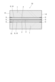
- FIG. 3 is a cross-sectional view of the assembled slab.
- FIG. 3 is a cross-sectional view showing a welding state (before welding) of a welded part when the base material and the laminate material are of the same quality.
- FIG. 3 is a cross-sectional view showing the welding state (after welding) of a welded part when the base material and the laminate material are of the same quality.
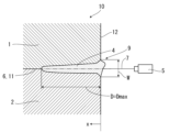
- FIG. 2 is a cross-sectional view showing a welding situation of a welded part when the base material and the laminate material are different (when there is deviation between the welded part and the contact surface).
- FIG. 3 is a cross-sectional view showing a welding condition of a welded part (a condition in which the deviation has been eliminated) when the base material and the laminate material are different.
- the present invention relates to a clad steel plate comprising a base material and a laminate joined to the base material, and an assembled slab as a rolled material for manufacturing the clad steel plate, and a method for manufacturing the assembled slab.
- the present invention is directed to a method for manufacturing the clad steel sheet.
- a cross-sectional view of the assembled slab 10 is shown in FIG.
- the assembled slab 10 includes a base material 1, a laminate material 2, a release agent 3, a laminate material 2, and a base material 1, which are laminated in this order.
- the contact portion 6 between the base material material 1 and the laminate material material 2 becomes the joint surface 14, and the contact surface between the laminate material materials 2 with the release agent 3 sandwiched therebetween becomes the separation surface 15. .
- the aiming position 8 of the welding beam 7 of the high-energy beam irradiation device 5 is set to the laminate material 2 and the base material 1, as shown in FIG. 2A.
- the weld metal 4 formed by penetration coincides with the position of the contact portion 6 in the weld portion 9, as shown in FIG. 2B.
- the base material 1 and the laminate material 2 are different metals.
- the weld metal 4 formed by penetration does not match the position of the contact part 6 in the weld part 9, it will be formed biased toward one metal. Therefore, the contact portion 6 between the laminate material 2 and the base material 1 cannot be welded to a sufficient depth.
- the welding depth at the contact portion 6 between the laminate material 2 and the base material 1 is referred to as "penetration depth D.”
- the penetration depth D was used as an index in a cross section perpendicular to both the surface (contact surface 11) constituted by the contact part 6 and the end surface 12 of the assembled slab 10. It was considered good if the penetration depth D was 22 mm or more.
- ratio of thermal conductivity difference between base material and laminate material ⁇ ( ⁇ high temperature It was found that the welding misalignment distance increases in proportion to the thermal conductivity of the conductive material/thermal conductivity of the low thermal conductivity material). Weld metal 4 shifts to the low thermal conductivity side.
- the aim position 8 of the welding beam 7 of the high-energy beam irradiation device 5 is not aligned with the contact part 6 between the laminate material 2 and the base material 1, and the aim position 8 is A test was conducted in which the contact portion 6 was shifted by a distance z (hereinafter referred to as "offset distance z").
- offset distance z a distance z
- the method for manufacturing an assembled slab of the present invention has been made based on such knowledge, and uses high-energy beam welding for the contact portion 6 between the base material 1 and the laminate material 2 on the end face 12 of the assembled slab 10.
- high energy beam welding the aiming position 8 of the welding beam 7 is shifted from the contact portion 6 to the high thermal conductivity material side.
- the ratio ⁇ of thermal conductivity between the base material and the laminate material and the offset distance z were variously changed to investigate the relationship between the two that could increase the penetration depth D.
- the method for manufacturing an assembled slab of the present invention is clearly effective when the ratio ⁇ of thermal conductivity between the base material 1 and the laminate material 2 is 2.5 or more, and in this case, The effect can be effectively enjoyed by setting the deviation (offset distance z) between the aiming position 8 of the welding beam 7 and the contact portion 6 to be 1 mm or more toward the high thermal conductivity material side. More specifically, when the offset distance z toward the high thermal conductivity material side is within the range of formula (3) below, corresponding to the thermal conductivity ratio ⁇ , the penetration depth D must be kept within a suitable range. I can do it. 0.35 ⁇ 0.86 ⁇ z ⁇ 0.35 ⁇ +0.14 (3)
- the welded part 9 of the base material 1 and the laminate material 2 is formed by high-energy beam welding.
- the ratio between the bead width W and the penetration depth D of the weld metal satisfies the following formula (1). 3.5 ⁇ D/W ⁇ 5.0 (1)
- the welding depth at the contact portion between the laminate material and the base material material is defined as the aforementioned decoy "penetration depth D”
- the width of the weld metal at the position of the end face is defined as the "bead width W”.
- the present invention can be applied by setting an incident angle to the welding beam of high-energy beam welding or by defocusing the welding beam, if necessary.
- Electron beam welding and laser welding can be used as high-energy beam welding.
- electron beam welding is used as high-energy beam welding, it is preferable to perform welding in a vacuum of 0.1 kPa or less. If welding is performed in a vacuum of 0.1 kPa or less, the crimped surfaces of the base material 1 and the laminate material 2 can be suitably crimped and then welded and sealed.
- beam deflection can be used. It is preferable that the beam deflection is circular and the deflection diameter ⁇ is 3 mm or more. By making the beam deflection circular, the effect of stirring the weld metal is exhibited, and by making the deflection diameter ⁇ 3 mm or more, the effect of melting a wider area is exhibited.
- the upper limit of the offset distance z is set to less than half of the deflection diameter ⁇ . This allows both materials to be melted.
- a method can be used in which a hole for evacuation is made in the base material 1 in advance, and after welding the four circumferences by laser welding, evacuation is performed using a vacuum pump.
- the assembled slab of the present invention manufactured by the method for manufacturing an assembled slab of the present invention has a base material material 1, a lamination material material 2, a release agent 3, a lamination material material 2, and a base material material 1 laminated in this order.
- the base material 1 and the laminate material 2 have a thermal conductivity ratio ⁇ (the numerator is the one with larger thermal conductivity) that differs by 2.5 or more, and the base material 1 at the end surface 12 of the assembled slab 10
- the contact portion 6 with the laminate material 2 is high-energy beam welded, and the weld metal 4 of the weld portion 9 melts in a cross section perpendicular to both the surface of the contact portion 6 and the end surface 12 of the assembled slab 10.
- the depth D is 22 mm or more, and the ratio of the bead width W to the penetration depth D satisfies the above formula (1).
- the thermal conductivity ratio ⁇ of the base material 1 and the laminate material 2 differs by 2.5 or more, the aiming position 8 of the welding beam 7 of the high-energy beam irradiation device 5 is set to the laminate material 2 and the laminate material 2 as in the conventional method. If it is made to coincide with the contact portion 6 with the base material 1, a deviation will occur between the width center of the weld metal and the contact portion, and the penetration depth D will be less than 22 mm.
- the base material 1 and the laminate material 2 have a thermal conductivity ratio ⁇ that differs by 2.5 or more. Even in this case, the deviation between the width center of the weld metal and the contact portion is reduced, and the penetration depth D becomes 22 mm or more.
- the method for manufacturing a clad steel plate of the present invention is characterized by rolling the assembled slab manufactured by the method for manufacturing an assembled slab of the present invention, or the assembled slab of the present invention, in a hot rolling process.
- spacers as described in Patent Document 2 are not used in the assembled slab, there is no need for the cost of procuring and processing spacers, and there is no need to cut out the spacer placement portion after rolling, resulting in poor rolling yield. There is no concern that the spacer will remain in the product.
- joining is not performed while supplying filler (filler metal) as described in Patent Document 4, there is no need to incur costs for filler procurement and equipment for supplying filler into the high-energy beam welding machine. .
- the method for manufacturing a clad steel plate of the present invention further includes, after hot rolling, cutting and removing the four circumferential welds of the clad steel plate, and separating the clad steel plates using a release agent applied to the interface between the laminates as a starting point. shall be.
- High alloy steel such as stainless steel, and Ni-based alloy can be suitably used as the material for the clad steel plates and the assembly slab. Further, as the base material of the clad steel plate and the base material of the assembled slab, steel such as carbon steel or low alloy steel can be suitably used.
- Weld metal 4 was exposed by etching in a cross section perpendicular to both the surface (contact surface 11) constituted by contact portion 6 and the end surface 12 of the assembled slab, and the bead width W and penetration depth D of weld metal 4 were measured. .
- the results are shown in Table 2.
- the quality of the obtained welded material was evaluated.
- Rollability is evaluated using the penetration depth D and formula (1).
- D ⁇ 22 mm and formula (1) compatible is S (pass)
- D ⁇ 22 mm and formula (1) nonconforming is G (pass)
- D ⁇ 22 mm. was marked as X (fail).
- the yield loss was evaluated using the weld depth Dmax, and Dmax ⁇ 40 mm was graded S (pass), Dmax ⁇ 50 mm was graded G (pass), and Dmax>50 mm was graded X (fail).
- Regarding the overall evaluation in the evaluation of rollability and yield loss, if both are S, S (pass), if either or both are G and do not contain X, G (pass), if any contains X was marked as X (fail).
- Comparative example No. 8 is the result of welding between the same materials, and is outside the scope of the present invention. Comparative example no. In Comparative Example No. 9 and 10, no offset was provided when welding different materials. In Nos. 11 and 12, the aiming position of the welding beam was shifted from the contact area to the low thermal conductivity material side, and the penetration depth D was less than 22 mm in all cases.
Landscapes
- Engineering & Computer Science (AREA)
- Mechanical Engineering (AREA)
- Physics & Mathematics (AREA)
- Optics & Photonics (AREA)
- Plasma & Fusion (AREA)
- Pressure Welding/Diffusion-Bonding (AREA)
- Welding Or Cutting Using Electron Beams (AREA)
Priority Applications (3)
| Application Number | Priority Date | Filing Date | Title |
|---|---|---|---|
| KR1020247033591A KR20240158976A (ko) | 2022-03-10 | 2023-02-20 | 조립 슬래브의 제조 방법 및 조립 슬래브, 그리고 클래드 강판의 제조 방법 |
| JP2024506027A JP7780110B2 (ja) | 2022-03-10 | 2023-02-20 | 組立スラブの製造方法、及び組立スラブ、並びにクラッド鋼板の製造方法 |
| CN202380025687.1A CN118900739A (zh) | 2022-03-10 | 2023-02-20 | 组装坯料的制造方法、组装坯料以及包层钢板的制造方法 |
Applications Claiming Priority (2)
| Application Number | Priority Date | Filing Date | Title |
|---|---|---|---|
| JP2022-037264 | 2022-03-10 | ||
| JP2022037264 | 2022-03-10 |
Publications (1)
| Publication Number | Publication Date |
|---|---|
| WO2023171350A1 true WO2023171350A1 (ja) | 2023-09-14 |
Family
ID=87936888
Family Applications (1)
| Application Number | Title | Priority Date | Filing Date |
|---|---|---|---|
| PCT/JP2023/006092 Ceased WO2023171350A1 (ja) | 2022-03-10 | 2023-02-20 | 組立スラブの製造方法、及び組立スラブ、並びにクラッド鋼板の製造方法 |
Country Status (4)
| Country | Link |
|---|---|
| JP (1) | JP7780110B2 (https=) |
| KR (1) | KR20240158976A (https=) |
| CN (1) | CN118900739A (https=) |
| WO (1) | WO2023171350A1 (https=) |
Citations (5)
| Publication number | Priority date | Publication date | Assignee | Title |
|---|---|---|---|---|
| JPS60177980A (ja) * | 1984-02-27 | 1985-09-11 | Toshiba Corp | 複合材の製造方法 |
| JPS63295078A (ja) * | 1987-05-26 | 1988-12-01 | Sumitomo Metal Ind Ltd | クラッドスラブの組み立て方法 |
| JP2012061474A (ja) * | 2010-08-16 | 2012-03-29 | Hitachi Metals Ltd | 異種金属の接合方法および異種金属からなる接合物 |
| JP2021143387A (ja) * | 2020-03-12 | 2021-09-24 | 日鉄ステンレス株式会社 | クラッド鋼板およびその製造方法 |
| JP2021186861A (ja) * | 2020-06-04 | 2021-12-13 | 古河電気工業株式会社 | 溶接方法、溶接装置、および製品 |
Family Cites Families (8)
| Publication number | Priority date | Publication date | Assignee | Title |
|---|---|---|---|---|
| JPS5213456A (en) | 1975-07-23 | 1977-02-01 | Nippon Steel Corp | Composite slab for hot rolling |
| JPS5213457A (en) * | 1975-07-23 | 1977-02-01 | Nippon Steel Corp | Apparatus for manufacturing clad steel |
| JPS61115688A (ja) * | 1984-11-07 | 1986-06-03 | Sumitomo Electric Ind Ltd | 異種金属の接合方法 |
| JPS6245485A (ja) | 1985-08-21 | 1987-02-27 | Nippon Kokan Kk <Nkk> | クラツド金属板の製造方法 |
| JP2005254282A (ja) | 2004-03-11 | 2005-09-22 | Nippon Steel Corp | レーザーによる突合せ溶接金属板の製造方法 |
| CN107075645B (zh) | 2014-11-11 | 2020-06-16 | 杰富意钢铁株式会社 | Ni合金包层钢板及其制造方法 |
| WO2020175573A1 (ja) | 2019-02-27 | 2020-09-03 | Jfeスチール株式会社 | 組立スラブおよびその製造方法ならびにクラッド鋼材の製造方法 |
| JP7052766B2 (ja) | 2019-03-28 | 2022-04-12 | Jfeスチール株式会社 | 組立スラブの組立方法及びこれを用いたクラッド鋼板の製造方法並びに組立スラブ |
-
2023
- 2023-02-20 KR KR1020247033591A patent/KR20240158976A/ko active Pending
- 2023-02-20 WO PCT/JP2023/006092 patent/WO2023171350A1/ja not_active Ceased
- 2023-02-20 JP JP2024506027A patent/JP7780110B2/ja active Active
- 2023-02-20 CN CN202380025687.1A patent/CN118900739A/zh active Pending
Patent Citations (5)
| Publication number | Priority date | Publication date | Assignee | Title |
|---|---|---|---|---|
| JPS60177980A (ja) * | 1984-02-27 | 1985-09-11 | Toshiba Corp | 複合材の製造方法 |
| JPS63295078A (ja) * | 1987-05-26 | 1988-12-01 | Sumitomo Metal Ind Ltd | クラッドスラブの組み立て方法 |
| JP2012061474A (ja) * | 2010-08-16 | 2012-03-29 | Hitachi Metals Ltd | 異種金属の接合方法および異種金属からなる接合物 |
| JP2021143387A (ja) * | 2020-03-12 | 2021-09-24 | 日鉄ステンレス株式会社 | クラッド鋼板およびその製造方法 |
| JP2021186861A (ja) * | 2020-06-04 | 2021-12-13 | 古河電気工業株式会社 | 溶接方法、溶接装置、および製品 |
Also Published As
| Publication number | Publication date |
|---|---|
| CN118900739A (zh) | 2024-11-05 |
| KR20240158976A (ko) | 2024-11-05 |
| JPWO2023171350A1 (https=) | 2023-09-14 |
| JP7780110B2 (ja) | 2025-12-04 |
Similar Documents
| Publication | Publication Date | Title |
|---|---|---|
| US7752728B2 (en) | Method of producing a material composite with explosion-welded intermediate piece | |
| CN107427950B (zh) | 使用间隔物焊接不可直接彼此焊接的金属基材料的方法 | |
| CN102639278A (zh) | 对接焊接接头及其制造方法 | |
| JP6619232B2 (ja) | 溶接方法 | |
| EP0406688B1 (en) | Method for manufacturing titanium clad steel plate | |
| CN113070575B (zh) | 双金属复合板的无中间层对接焊焊接方法及焊接结构 | |
| WO2023171350A1 (ja) | 組立スラブの製造方法、及び組立スラブ、並びにクラッド鋼板の製造方法 | |
| CN107649513A (zh) | 一种复合轧制用组坯结构及其生产工艺 | |
| CN112775550A (zh) | T2紫铜和301不锈钢异种材料的激光焊接方法 | |
| KR20170047824A (ko) | 티바의 제조방법 | |
| JP6787534B1 (ja) | 組立スラブおよびその製造方法ならびにクラッド鋼材の製造方法 | |
| KR102840230B1 (ko) | 클래드 강관 제조방법 | |
| Chung et al. | Microstructure and mechanical properties in the friction stir welded C70600 alloy | |
| KR102762251B1 (ko) | 스테인리스와 탄소강을 포함하는 클래드 강의 용접방법 및 이 방법으로 제조된 클래드 강 | |
| JPH10263823A (ja) | チタンクラッド鋼板の溶接方法及び防食構造体 | |
| JPH11320125A (ja) | 施工性に優れたクラッド鋼板 | |
| JP2019126825A (ja) | 溶接継手 | |
| KR100466335B1 (ko) | 담수설비 증발기의 격벽 제작방법 | |
| Leon-Henao et al. | Assessment of Super Duplex Stainless Steel Welding using Hyper Duplex Filler Metal: Microstructure and Corrosion Performance | |
| JP2023147358A (ja) | 重ね隅肉溶接継手の製造方法、重ね隅肉溶接継手の重ね幅の設定方法および重ね隅肉溶接継手 | |
| CN120170231A (zh) | 双金属爆炸复合钢板及其对接方法、双金属爆炸复合钢板对接件 | |
| Caccese | Fatigue in laser welds | |
| CN120862261A (zh) | 制造多层不锈钢复合板坯的方法 | |
| JPH03275286A (ja) | 炭素鋼耳付ステンレスクラッド鋼板の製造法 | |
| JPS63183777A (ja) | 高能率スラブ組立方法 |
Legal Events
| Date | Code | Title | Description |
|---|---|---|---|
| 121 | Ep: the epo has been informed by wipo that ep was designated in this application |
Ref document number: 23765140 Country of ref document: EP Kind code of ref document: A1 |
|
| ENP | Entry into the national phase |
Ref document number: 2024506027 Country of ref document: JP Kind code of ref document: A |
|
| WWE | Wipo information: entry into national phase |
Ref document number: 202380025687.1 Country of ref document: CN |
|
| ENP | Entry into the national phase |
Ref document number: 20247033591 Country of ref document: KR Kind code of ref document: A |
|
| WWE | Wipo information: entry into national phase |
Ref document number: 1020247033591 Country of ref document: KR |
|
| NENP | Non-entry into the national phase |
Ref country code: DE |
|
| 122 | Ep: pct application non-entry in european phase |
Ref document number: 23765140 Country of ref document: EP Kind code of ref document: A1 |