WO2023170939A1 - 推定装置、推定方法及び記憶媒体 - Google Patents
推定装置、推定方法及び記憶媒体 Download PDFInfo
- Publication number
- WO2023170939A1 WO2023170939A1 PCT/JP2022/010942 JP2022010942W WO2023170939A1 WO 2023170939 A1 WO2023170939 A1 WO 2023170939A1 JP 2022010942 W JP2022010942 W JP 2022010942W WO 2023170939 A1 WO2023170939 A1 WO 2023170939A1
- Authority
- WO
- WIPO (PCT)
- Prior art keywords
- load
- vehicle
- tire
- transition
- abnormality
- Prior art date
- Legal status (The legal status is an assumption and is not a legal conclusion. Google has not performed a legal analysis and makes no representation as to the accuracy of the status listed.)
- Ceased
Links
Images


Classifications
-
- G—PHYSICS
- G01—MEASURING; TESTING
- G01M—TESTING STATIC OR DYNAMIC BALANCE OF MACHINES OR STRUCTURES; TESTING OF STRUCTURES OR APPARATUS, NOT OTHERWISE PROVIDED FOR
- G01M17/00—Testing of vehicles
- G01M17/007—Wheeled or endless-tracked vehicles
-
- G—PHYSICS
- G08—SIGNALLING
- G08G—TRAFFIC CONTROL SYSTEMS
- G08G1/00—Traffic control systems for road vehicles
Definitions
- the present disclosure relates to a technology for estimating vehicle information, and particularly relates to a technology for estimating a range traveled by a vehicle while the brakes are applied.
- Patent Document 1 describes a control system that acquires pressure information including pressure values from vehicles passing on a road, which is output from a pressure sensor installed at a stop position on a road. This control system acquires sudden braking information indicating a sudden braking operation by a vehicle based on pressure information, and generates a control signal for controlling a traffic light installed on a road based on the sudden braking information.
- Patent Document 2 discloses a slip system that uses the outputs of at least three load sensors that act on plates buried in the road surface and the output of a wheel speed measurement unit to determine the tire load center of gravity and the locus of the tire load center of gravity. A rate measuring device is described. This slip rate measuring device calculates ground speed and slip rate from the tire load center of gravity and the locus of the tire load center of gravity.
- Patent Document 3 describes a tire road surface condition measuring device that measures the ground contact shape of the tire and the ground contact force on the road surface using a load detector embedded in the measurement road surface, and records the measured values in chronological order.
- the load detectors are lined up and buried in a detection area in a transverse direction substantially perpendicular to the vehicle running direction, which is wider than the ground contact width of the tire when the vehicle is stationary.
- the tire road condition measuring device further includes protrusion detectors on the outside of both ends of the detection area, and additionally includes a speed measuring device.
- the protrusion detector detects when a tire running on the measurement road protrudes from the detection area.
- the speed measuring device measures the traveling speed of the vehicle when passing through an area where the load detector is installed.
- the control system described in Patent Document 1 can determine whether a sudden brake has been applied to a vehicle passing a stop line.
- the slip rate measuring device disclosed in Patent Document 2 can obtain the locus of the tire load center of gravity.
- the tire road surface shape measuring device disclosed in Patent Document 3 can obtain a time series of load measurements measured at each point when a tire passes through a plurality of points arranged in a straight line.
- One of the purposes of the present disclosure is to provide an estimation device and the like that can estimate the range in which a vehicle has moved while the brakes are applied.
- An estimation device includes a load data acquisition unit that acquires measurement data of changes in the magnitude of a load measured by a plurality of load sensors embedded in a road surface installation area, and , a specifying means for specifying a vehicle load transition which is a change in the position and size of the load due to the tires of the same vehicle, and a brake range in which the vehicle moved with the brakes applied based on the specified vehicle load transition. and an output means for outputting the estimated brake range.
- An estimation method acquires measurement data of the change in load magnitude measured by a plurality of load sensors embedded in a road surface installation area, and from the measurement data,
- the vehicle load transition which is the change in the position and magnitude of the load due to the tires, is specified, and from the specified vehicle load transition, the brake range in which the vehicle has moved with the brake applied is estimated, and the estimated brake range is estimated. Output the brake range.
- a storage medium includes a load data acquisition process of acquiring measurement data of a change in the magnitude of a load measured by a plurality of load sensors embedded in a road surface installation area, and , a specific process for specifying a vehicle load transition, which is a transition in the position and magnitude of the load due to the tires of the same vehicle, and a braking range in which the vehicle moved while the brakes were applied, from the identified vehicle load transition.
- a program is stored that causes a computer to execute a range estimation process for estimating the brake range, and an output process for outputting the estimated brake range.
- One aspect of the present disclosure is also realized by the above-mentioned program.
- the present disclosure has the effect of being able to estimate the range in which the vehicle has moved while the brakes are applied.
- FIG. 1 is a block diagram illustrating an example of the configuration of an estimation device according to a first embodiment of the present disclosure.
- FIG. 2 is a flowchart illustrating an example of the operation of the estimation device according to the first embodiment of the present disclosure.
- FIG. 3 is a block diagram illustrating an example of the configuration of an estimation system according to the second embodiment of the present disclosure.
- FIG. 4 is a flowchart illustrating an example of the operation of the estimation device according to the second embodiment of the present disclosure.
- FIG. 5 is a block diagram illustrating an example of a configuration of an estimation system according to a third embodiment of the present disclosure.
- FIG. 6 is a flowchart illustrating an example of the operation of the estimation device according to the third embodiment of the present disclosure.
- FIG. 1 is a block diagram illustrating an example of the configuration of an estimation device according to a first embodiment of the present disclosure.
- FIG. 2 is a flowchart illustrating an example of the operation of the estimation device according to the first embodiment of the present disclosure.
- FIG. 7 is a block diagram illustrating an example of the configuration of an estimation system according to the fourth embodiment of the present disclosure.
- FIG. 8 is a flowchart illustrating an overall example of the operation of the estimation device according to the fourth embodiment of the present disclosure.
- FIG. 9 is a flowchart illustrating an example of the operation of the driving abnormality detection process of the estimation device according to the fourth embodiment of the present disclosure.
- FIG. 10 is a flowchart illustrating an example of the operation of the abnormal sound detection process of the estimation device according to the fourth embodiment of the present disclosure.
- FIG. 11 is a diagram illustrating an example of the hardware configuration of a computer that can implement the estimation device according to the embodiment of the present disclosure.
- FIG. 1 is a block diagram illustrating an example of the configuration of an estimation device according to a first embodiment of the present disclosure.
- the estimation device 10 includes a load data acquisition section 110, a specification section 120, a range estimation section 140, and an output section 150.
- the load data acquisition unit 110 acquires measurement data of changes in the magnitude of the load measured by a plurality of load sensors embedded in the installation area of the road surface.
- the installation area is an area of the road where the load sensor is installed.
- the specifying unit 120 specifies a vehicle load transition, which is a change in the position and magnitude of the load caused by the tires of the same vehicle, from the measurement data.
- the range estimating unit 140 estimates the braking range in which the vehicle has moved while the brakes are applied, based on the specified vehicle load transition.
- the output unit 150 outputs the estimated brake range.
- the load sensor is a pressure sensor that can be embedded in the road surface.
- a plurality of load sensors are buried in a road surface in a range including road intersections.
- the plurality of load sensors may be buried in the road surface in a range including a road crosswalk.
- the plurality of load sensors may be embedded in the road surface in a range including a range where a car can be stopped by a traffic signal.
- the plurality of load sensors may be buried in the road surface in a range including the stop line.
- the plurality of load sensors may be buried at predetermined intervals.
- the distance between the plurality of load sensors in the vehicle traveling direction may be different from the distance between the plurality of load sensors in the cross-road direction.
- the pattern of the positions where the plurality of load sensors are buried may be a regular pattern.
- the pattern of the positions where the plurality of load sensors are buried does not have to be a regular pattern.
- the distance between the plurality of load sensors is determined experimentally ( For example, it may be set to several centimeters.
- the distance between the plurality of load sensors may be determined for a plurality of types of vehicles so that different tires of a running automobile do not apply loads to adjacent load sensors. Different tires in this case include different tires of the same vehicle and tires of different vehicles.
- the positions of the plurality of load sensors are determined experimentally, for example, for a plurality of types of vehicles, so that the installation position of at least one sensor is included in the range where the tires of the running car touch the ground. It may be specified.
- the positions of the plurality of load sensors may be determined for a plurality of types of vehicles so that different tires of a running automobile do not apply loads to adjacent load sensors.
- the position where each of the plurality of load sensors is buried is obtained in advance by measurement or the like. Information on the position where each of the plurality of load sensors is buried is given to the specifying unit 120 in advance.
- the load sensor measures the load applied to the road by the vehicle's tires.
- the load data acquisition unit 110 may be configured to acquire load measurement values from each of the plurality of load sensors, for example, at the same timing.
- a plurality of load sensors may be configured to measure the load at the same timing and transmit the measured value of the measured load to the load data acquisition unit 110.
- the load data acquisition unit 110 acquires load magnitude measurement values measured at the same timing at a plurality of points in time (that is, changes in load magnitude measurement values, in other words, measurement data of load magnitude transitions). It may be acquired from each of a plurality of load sensors.
- the load data acquisition unit 110 may generate data (hereinafter also simply referred to as measurement data) of the measured value of the load for each load sensor, which is arranged in order of measurement time, for example.
- the identifying unit 120 determines the position of the tire and the magnitude of the load that the tire applies to the road surface from the measured values of the load at the same timing measured by a plurality of load sensors for each of the timings at which the load is measured. Estimate. For example, when a measurement value at a new timing (hereinafter referred to as the latest timing) is obtained, the identification unit 120 determines the position of the tire and the magnitude of the load that the tire applies to the road surface from the measurement value of the load at the latest timing. Estimate.
- the identification unit 120 tracks the position of the same tire at each timing when the load is measured.
- the time series of the positions of tires whose positions are detected at one or more timings and which are considered to be tires being tracked will be referred to as a tire position transition.
- the tire being tracked is a tire that is the target of a process in which, when a measured value at the latest timing is obtained, the position at the latest timing is selected from among the estimated tire positions at the latest timing.
- the identifying unit 120 specifies, for example, that the position of the tire being tracked is included in the range in which the tire can move from the latest position in the transition of the tire position to the timing of the estimated measurement value and the latest timing. Select the tire position with the latest timing. The range in which the tire can move between a certain timing and another timing may be appropriately determined in advance.
- the identifying unit 120 adds the selected tire position at the latest timing to the tire position transition of the tire being tracked as the tire position at the latest timing. When a plurality of tire positions at the latest timing are selected, the identification unit 120 adds all the positions of the selected tires at the latest timing to the tire position transition of the tire being tracked, and adds the position of the tire at the latest timing to the tire position transition of the tire being tracked. You can add it as The identifying unit 120 may add the same tire position at the latest timing to the tire position transition of each of the plurality of tires being tracked.
- the identification unit 120 estimates, for each tire, the position of the tire and the magnitude of the load that the tire applies to the road surface at each timing when the measured value is obtained. Therefore, by estimating the change in the position of the tire being tracked, the identification unit 120 can estimate the change in the position of the tire being tracked and the magnitude of the load that the tire applies to the road surface up to the latest timing for each tire. be specific.
- the transition between the position of the tire and the magnitude of the load that the tire applies to the road surface is referred to as a tire load transition.
- the specifying unit 120 sets tires whose positions have not been added to the tire position transition of the tires that are being tracked as new tires that are being tracked. In other words, the specifying unit 120 selects the tire position that has not been added to the tire position transition of the tire currently being tracked among the tire positions at the latest timing, to the position of the tire that has not been added to the tire position transition of the tire that is currently being tracked. tire position.
- the identification unit 120 tracks the vehicle using the transition of the tire position of the tire being tracked. This vehicle tracking is the determination of the latest tire position of the tires being tracked that are determined to be tires of the same vehicle.
- the vehicle being tracked is a vehicle whose tires can be identified as the tires being tracked.
- the identification unit 120 calculates changes in relative positions between tires between successive timings in the history of tire positions of the vehicle being tracked. Then, whether the change in the relative position of the tire from the previous timing in the tire position at the latest timing (hereinafter referred to as relative position change) is included in the range of possible changes in the relative position of the tires of the same vehicle. Determine whether or not.
- the identification unit 120 identifies a relative position change in the tire position at the latest timing that is not included in the range of possible changes in the relative position of tires of the same vehicle.
- the identifying unit 120 identifies the tire whose tire position at the latest timing is the cause of the identified relative position change.
- the relative position of two tires in the description of the identifying unit 120 indicates, for example, the distance between the two tires.
- the identification unit 120 determines, at the latest timing, the number of other tires that are being tracked as tires of the same vehicle and whose relative positions are not within the range of possible changes in the relative positions of tires of the same vehicle. , the tire with the largest number of occurrences may be identified as the cause of the relative position change.
- a change in the relative position that is within the range of possible changes in the relative position of tires of the same vehicle will be referred to as satisfying the same vehicle standard.
- the change in relative position is not within the range of possible changes in the relative position of tires of the same vehicle, it is expressed as not satisfying the same vehicle standard.
- the identifying unit 120 determines the position at the latest timing of a tire for which the change in relative position does not satisfy the same vehicle standard and for which the number of other tires being tracked as tires of the same vehicle is the greatest. may be specified as the cause of the relative position change. For example, at the latest timing, the identification unit 120 specifies that the change in relative position does not satisfy the same vehicle standard, and that the number of other tires being tracked as tires of the same vehicle is more than half the number of tires of that vehicle. The tire position of the tire at the latest timing may be specified as the cause of the relative position change.
- the specifying unit 120 excludes the tire position at the latest timing of a tire whose tire position at the latest timing has been specified as a factor of the relative position change from the change in the tire position of that tire.
- the identifying unit 120 may repeat identifying the cause of the relative position change and excluding the identified factor from the tire position transition until there is no change in the relative position that does not satisfy the same vehicle standard.
- the identifying unit 120 determines the tire position where the change in relative position at the latest timing with respect to other tires of the same vehicle is the smallest. Identify. In this case, specifically, the identifying unit 120 identifies the tire position where the representative value (for example, average value) of the magnitude of change in relative position at the latest timing with respect to other tires of the same vehicle is the smallest. Then, the specifying unit 120 excludes tire positions other than the specified tire position from among the plurality of tire positions at the latest timing included in the transition of the tire position of one tire.
- the identification unit 120 extracts tires that are being tracked and are not tires of the vehicle that is being tracked. Then, the specifying unit 120 extracts, from the extracted tires being tracked, combinations of tires being tracked whose relative positions at the latest timing are included in a range of possible relative positions of tires of the same vehicle. The identification unit 120 identifies the tire being tracked included in the extracted combination as the tire of the new vehicle being tracked. There is a combination of tire position changes of multiple tracked tires where the latest relative position is within the range of possible relative positions of the same vehicle's tires and is not a tire position change of the tracked vehicle's tires. In this case, the identifying unit 120 determines the plurality of tires being tracked as a new vehicle being tracked.
- the range of possible relative positions of tires of the same vehicle may be determined as appropriate for each vehicle type.
- the vehicle type may be a two-wheeled vehicle or a four-wheeled vehicle.
- the types of four-wheeled vehicles may be further subdivided into light vehicles, small vehicles, regular vehicles, large vehicles, and the like.
- the vehicle types are not limited to these examples.
- the vehicle type may be determined as appropriate.
- the identification unit 120 may delete the history of the tire being tracked for which the latest tire position has not been obtained for a predetermined number of timings. Further, the identification unit 120 may exclude a vehicle being tracked that has run out of tires from the vehicles being tracked.
- the range estimating unit 140 uses information on tire load changes of the vehicle's tires to identify the range in which the vehicle has moved while the brakes are applied.
- the range of movement while the brakes are applied may be expressed, for example, by the starting point and end point of the position of each tire of the movement of the vehicle while the brakes are applied in the tire load transition of the tires of the vehicle.
- the range of movement with the brakes applied may be represented by, for example, the history of the position of each tire during the movement of the vehicle with the brakes applied, in the tire load transition of the tires of the vehicle.
- the range estimation unit 140 may determine whether the vehicle is in a braked state based on the ratio of the load on the front wheels of the vehicle to the load on the rear wheels of the vehicle. In this case, the range estimation unit 140 determines whether the tire is a front wheel or a rear wheel based on the moving direction of the vehicle (specifically, the moving direction of each tire).
- the front wheels in this case refer to the wheels located in front of the vehicle in the direction of movement of the vehicle.
- the rear wheels in this case refer to wheels located at the rear of the vehicle in the direction of movement of the vehicle.
- the front wheels and rear wheels in this case are not necessarily the same as the structural front wheels and rear wheels of the vehicle.
- a state in which the vehicle is moving with the brake applied will be referred to as a brake effective state.
- the range estimation unit 140 may determine that the vehicle has entered the brake effective state (in other words, the brake effective state of the vehicle has started) when the ratio of the rear wheel load to the front wheel load has decreased.
- the range estimating unit 140 determines that the rate of decrease in the rear wheel load is a predetermined rate during a period in which the ratio of the rear wheel load to the front wheel load is decreasing, and furthermore, the ratio of the rear wheel load to the front wheel load is decreasing.
- a criterion hereinafter referred to as a reduction rate criterion
- the reduction rate criterion is, for example, that the reduction rate is greater than a reduction rate threshold. If the reduction rate takes a negative value when the load on the rear wheels decreases, the reduction rate criterion may be, for example, that the reduction rate is less than a reduction rate threshold. If it is determined that the vehicle has entered the brake effective state, the range estimating unit 140 sets the tire position at the time when the ratio of the rear wheel load to the front wheel load starts to decrease as the starting point of the brake effective state. good.
- the range estimating unit 140 determines that the vehicle is no longer in a brake effective state (in other words, the brake effective state of the vehicle has ended) when the ratio of the rear wheel load to the front wheel load increases and then becomes constant. You may do so.
- the range estimating unit 140 estimates the rear wheel load in a state where the ratio of the rear wheel load to the front wheel load becomes constant after increasing, and in addition, the ratio of the rear wheel load to the rear wheel load before the ratio increases. It may be determined that the vehicle is no longer in the brake effective state when the increase rate of the brake value satisfies the increase rate criterion.
- the rate of increase criterion is, for example, that the rate of increase is greater than a threshold value of the rate of increase.
- the range estimation unit 140 may set the end point of the effective brake state to the tire position at the time when the ratio of the rear wheel load to the front wheel load increases and becomes constant. .
- the method for determining whether the brakes are applied to the vehicle is not limited to the above example.
- the output unit 150 outputs the brake range (specifically, brake range information) to, for example, an output destination device.
- the output destination device may be a storage device.
- the output unit 150 outputs the brake range to, for example, a storage device.
- the output unit 150 stores the brake range in the storage device.
- the output destination device may be a media reader/writer device that stores data on a storage medium.
- the output unit 150 outputs the brake range to the media reader/writer device.
- the media reader/writer device receives the brake range and stores the received brake range in a storage medium.
- the output unit 150 stores the brake range in the storage medium via the medium reader/writer device.
- the output destination device may be, for example, another information processing device that is communicably connected to the estimation device 10 via a communication network.
- the output unit 150 outputs the brake range to another information processing device.
- the output destination device is not limited to the above example.
- FIG. 2 is a flowchart illustrating an example of the operation of the estimation device 10 according to the first embodiment of the present disclosure.
- the load data acquisition unit 110 first acquires load measurement data from the load sensor (step S11).
- the identification unit 120 identifies the vehicle load transition of the same vehicle from the measurement data (step S12).
- the range estimating unit 140 estimates the brake range within which the vehicle has moved while the brakes are applied, based on the vehicle load transition (step S13).
- the output unit 150 outputs the estimated brake range (step S14).
- the estimation device 10 may repeat the operation shown in FIG. 2.
- This embodiment has the effect that it is possible to estimate the range in which the vehicle has moved while the brakes are applied.
- the identifying unit 120 identifies the vehicle load transition of the same vehicle from the load measurement data measured by a plurality of load sensors embedded in the road surface.
- the vehicle load transition of the same vehicle represents the transition of the combination of the load position and load magnitude with respect to the road surface due to the tires of the same vehicle.
- the range estimating unit 140 estimates the brake range within which the vehicle has moved while the brakes are applied, based on the specified vehicle load transition.
- the identification unit 120 identifies the vehicle being tracked so that the change in the relative position of the tire being tracked of the vehicle being tracked at the latest timing from the relative position at the timing just before the same satisfies the above-mentioned same vehicle criterion. Determine the most recent timing tire position of each of the tires being tracked. Specifically, the identification unit 120 estimates the latest timing as the tire position of each of the tires being tracked of the vehicle being tracked at the latest timing so that the same vehicle criterion described above is satisfied at the latest timing. One tire position is specified from the tire positions determined. The identification unit 120 determines the tire position identified as the latest timing position of the tire of the vehicle being tracked and the magnitude of the load at that tire position as the latest timing position and load magnitude of the tire. Add to tire load transition.
- the identification unit 120 determines the latest timing of the tire.
- the tire position is estimated as follows, for example. Specifically, the specifying unit 120 first calculates the change in position of the tire whose latest position has been specified as described above, from the immediately previous timing. Further, the identification unit 120 calculates the relative position of the tire in the tire position transition of the tire being tracked of the vehicle being tracked. The specifying unit 120 determines the previous timing when the tire whose position at the previous timing has been obtained moves to the specified position as described above while maintaining the calculated relative position of the tire. Estimate the latest timing position of the tire whose position has been obtained.
- the identifying unit 120 extracts the position of the tire at the latest timing, which is included in a predetermined range based on the estimated position.
- the predetermined range based on the estimated position may be appropriately determined in advance. If a plurality of tire positions are extracted, the identifying unit 120 selects one tire position using a predetermined method. For example, the identification unit 120 selects the tire position closest to the estimated position among the plurality of extracted tire positions as the latest timing position of the tire for which the immediately preceding timing position has not been obtained. You may choose.
- the identification unit 120 selects the position selected as the latest timing position of a tire for which the immediately preceding timing position has not been obtained and the magnitude of the load at that position as the latest timing position and load magnitude of that tire. , is added to the tire load transition for that tire.
- the specifying unit 120 receives, for example, data of measured values of load magnitudes for each load sensor (i.e., the above-mentioned measured data) arranged in order of measurement time.
- the specifying unit may group the measured values of loads caused by the same tire from the measured values of loads measured at the same timing among the measured values included in the measurement data, using the position of the measured load sensor.
- the identification unit 120 groups load sensors that have measured a load greater than or equal to a predetermined minimum load value into one or more groups such that two load sensors that are adjacent to each other are included in the same group. It's fine.
- the specifying unit 120 then calculates a representative value (for example, one predetermined value among the maximum value, average value, median value, intermediate value, etc.) of the measured values of the loads included in the same group. Further, the specifying unit 120 calculates a representative value of the position where the measured values of the loads included in the same group are measured.
- the representative value of the position where the load measurement values included in the same group were measured may be, for example, the center of gravity of the position of the load sensor where the measurement values included in the same group were measured.
- the representative value of the position where the load measurement value included in the same group was measured is another value calculated from the position of the load sensor that measured the measurement value included in the same group (for example, the representative value in the direction of travel). (first position).
- a representative value of the measured load values included in the same group is hereinafter referred to as a tire load value.
- a representative value of a position where load measurements included in the same group are measured will be referred to as a tire load position.
- the position where a load is generated by one tire (hereinafter referred to as the tire load position) and the magnitude of the generated load (hereinafter referred to as the tire load size) are determined by the tire load position and tire load value.
- the position where the load from one tire is generated hereinafter referred to as tire load position
- tire load size the magnitude of the generated load
- the tire data value includes a combination of , hereinafter referred to as tire data value.
- the tire data value includes a combination of tire load position and tire load value for one tire at one timing.
- the identification unit 120 calculates tire data values (that is, combinations of tire load values and tire load positions) at multiple timings from measurement values measured by multiple load sensors at multiple timings. The identification unit 120 then determines the relationship between the combinations of tire load values and tire load positions (that is, the relationship between tire data values) calculated from the measured values at consecutive timings. That is, the specifying unit 120 selects the tire data value representing the load magnitude and load position at the next timing of the tire whose load magnitude and load position are represented by the tire data value at a certain timing. The specifying unit 120 then associates the tire data value at a certain timing with the tire data value at the next timing selected for that tire data value.
- tire data values that is, combinations of tire load values and tire load positions
- the identifying unit 120 determines that the magnitude of the change in tire load position between the tire data value at a certain timing and the tire data value at the next timing is within a range in which the vehicle can move between consecutive timings. It may be determined whether or not the As a result of the determination, if the magnitude of the change in the tire load position is within the range in which the vehicle can move between successive timings, the identifying unit 120 determines whether the tire data value at a certain timing and the tire data value at the next timing is within the range in which the vehicle can move between successive timings. It may be associated with tire data values.
- the range in which the vehicle can move between consecutive timings is not limited to the range in which the vehicle can move during normal driving. Movement of the vehicle between consecutive timings includes movement of the vehicle due to a collision.
- a combination of a tire data value at a certain timing and a tire data value at the next timing that are associated with each other is referred to as a tire data value set.
- the set of tire data values includes one tire data value at one timing and one tire data value at the next timing.
- the identification unit 120 generates a set of tire data values.
- FIG. 3 is a block diagram illustrating an example of the configuration of an estimation system according to the second embodiment of the present disclosure.
- the estimation system 1 of this embodiment includes an estimation device 100, a load sensor 200, and an output destination device 300.
- the estimation device 100 includes a load data acquisition section 110 , a specification section 120 , a running abnormality detection section 130 , a range estimation section 140 , and an output section 150 .
- the load sensor 200 of this embodiment is the same as the load sensor of the first embodiment.
- the output destination device 300 of this embodiment is the same as the output destination device of the first embodiment.
- the load data acquisition unit 110, the identification unit 120, the range estimation unit 140, and the output unit 150 of this embodiment are respectively the load data acquisition unit 110 of the first embodiment, and the output unit 150 of the first embodiment, except for the differences described below. This is the same as the specifying unit 120, the range estimating unit 140, and the output unit 150.
- the load data acquisition unit 110, the identification unit 120, the range estimation unit 140, and the output unit 150 of this embodiment are respectively the load data acquisition unit 110 of the first embodiment, and the output unit 150 of the first embodiment, except for the differences described below. It performs the same operations as the specifying unit 120, the range estimating unit 140, and the output unit 150.
- the running abnormality detection unit 130 detects the occurrence of a running abnormality of the vehicle based on at least one of changes in the position of the tires and changes in the vehicle load of the vehicle.
- An abnormality in vehicle running is, for example, when the magnitude of the acceleration of one of the vehicles being tracked becomes larger than a predetermined acceleration threshold.
- the magnitude of acceleration of the vehicle may be a representative value of the magnitude of acceleration of tires of the vehicle.
- the representative value of the magnitude of acceleration of a tire of a vehicle represents a statistical value such as an average value or a maximum value of acceleration of a plurality of tires of a vehicle.
- An abnormality in the running of the vehicle may be, for example, that the magnitude of acceleration of any of the tires being tracked becomes larger than a predetermined acceleration threshold. In these cases, the running abnormality detection unit 130 calculates the magnitude of the acceleration of the tire from the positional transition included in the tire positional transition.
- the acceleration threshold value may differ depending on the location of the road. Further, the acceleration threshold value may be different depending on the direction of acceleration. For example, in a place where a vehicle travels only when turning left, the acceleration threshold for the magnitude of acceleration in a direction where acceleration can occur when turning left may be smaller than the acceleration threshold for the magnitude of acceleration in a direction where acceleration is unlikely to occur when turning left.
- the direction in which acceleration may occur during a left turn is, for example, a direction to the left with respect to the traveling direction before the left turn.
- a direction in which acceleration is unlikely to occur when turning left is, for example, a direction to the right relative to the direction of travel before the left turn.
- the acceleration threshold for the magnitude of acceleration in a direction where acceleration is likely to occur when turning right may be smaller than the acceleration threshold for the magnitude of acceleration in a direction where acceleration is unlikely to occur when turning right.
- the direction in which acceleration may occur during a right turn is, for example, a direction to the right relative to the direction of travel before the right turn.
- a direction in which acceleration is unlikely to occur when turning right is, for example, a direction to the left with respect to the direction of travel before the right turn.
- the acceleration threshold for the magnitude of acceleration and deceleration in the straight-ahead direction may be larger than the acceleration threshold for the magnitude of acceleration in a direction different from the straight-ahead direction.
- the acceleration threshold for the magnitude of acceleration in the straight-ahead direction may be smaller than the acceleration threshold for the magnitude of deceleration in the straight-ahead direction.
- the location where the vehicle travels only when turning left, the location where the vehicle travels only when turning right, and the location where the vehicle travels straight may be determined in advance according to the shape of the road and traffic rules.
- the abnormal motion criterion is that the magnitude of tire or vehicle acceleration is greater than an acceleration threshold.
- the driving abnormality detection unit 130 detects a movement of the vehicle that satisfies an abnormal movement criterion as an abnormality.
- An abnormality in the running of the vehicle may be that the position of the tire deviates from the range that the tire can pass during normal running.
- the range through which the tires can pass during normal driving may be predetermined according to the shape of the road and traffic rules.
- An abnormality in the running of the vehicle may be, for example, a deviation of the tires from the road in the area of an intersection.
- the abnormality in the running of the vehicle may be, for example, the position of the tires entering the oncoming lane.
- the abnormal position criterion is that the position of the vehicle is included in an area other than the range through which tires can pass during normal driving of the vehicle.
- the driving abnormality detection unit 130 detects, as an abnormality, that the vehicle moves to a position that satisfies the abnormal position reference.
- the range estimating unit 140 estimates the braking range in which the vehicle has moved while the brakes are applied when the running abnormality detecting unit 130 detects an abnormality in the running of the vehicle.
- FIG. 4 is a flowchart illustrating an example of the operation of the estimation device 100 according to the second embodiment of the present disclosure.
- the load data acquisition unit 110 acquires load measurement data from the load sensor (step S101).
- the identification unit 120 identifies the vehicle load transition of the same vehicle from the measurement data (step S102).
- the running abnormality detection unit 130 detects an abnormality (step S103). Specifically, the driving abnormality detection unit 130 detects the above-mentioned abnormality in the driving of the vehicle.
- step S104 If no abnormality is detected (NO in step S104), the estimation device 100 ends the operation shown in FIG. 4.
- the range estimating unit 140 estimates the braking range in which the vehicle has moved while the brakes are applied from the vehicle load transition (step S105).
- the output unit 150 outputs the estimated brake range (step S106). Then, the estimation device 100 ends the operation shown in FIG. 4.
- the estimation device 100 may repeat the operation shown in FIG. 4.
- This embodiment has the effect of suppressing the output in the less important braking range.
- the reason is that when an abnormality is detected by the driving abnormality detection section 130, the range estimation section 140 estimates the brake range, and the output section 150 outputs the brake range. If no abnormality is detected, it is unlikely that a traffic accident has occurred. If there is a low possibility that a traffic accident has occurred, there is no need to obtain information on the braking range, so the estimated braking range is of low importance.
- FIG. 5 is a block diagram illustrating an example of a configuration of an estimation system according to a third embodiment of the present disclosure.
- the estimation system 2 of this embodiment includes an estimation device 101, a load sensor 200, an output destination device 300, and an imaging device 400.
- the estimation device 101 includes a load data acquisition section 110, a specification section 120, a running abnormality detection section 130, a range estimation section 140, an output section 150, and a video acquisition section 160.
- the load data acquisition unit 110, identification unit 120, running abnormality detection unit 130, range estimation unit 140, and output unit 150 of the present embodiment are respectively similar to those of the first embodiment, except for the differences described below.
- the load data acquisition section 110, identification section 120, the running abnormality detection section 130, the range estimation section 140, and the output section 150 It is the same as the load data acquisition section 110, the identification section 120, the running abnormality detection section 130, the range estimation section 140, and the output section 150.
- the load data acquisition unit 110, identification unit 120, running abnormality detection unit 130, range estimation unit 140, and output unit 150 of the present embodiment are respectively similar to those of the first embodiment, except for the differences described below. It performs the same operations as the load data acquisition section 110, the identification section 120, the running abnormality detection section 130, the range estimation section 140, and the output section 150.
- the imaging device 400 captures an image of the above-mentioned installation area.
- the imaging device 400 may include a plurality of imaging devices that capture images of the installation area from different directions.
- the resolution of the image captured by the imaging device 400 may be, for example, a resolution that allows the characters on the license plate of the vehicle traveling on the installation area to be recognized in the image of the vehicle traveling on the installation area.
- the video captured by the imaging device 400 is transmitted to the video acquisition unit 160.
- the video acquisition unit 160 receives the captured video from the imaging device 400.
- the video acquisition unit 160 retains the received video for a predetermined period of time after receiving the video.
- the imaging device 400 may transmit video data to the video acquisition unit 160, for example.
- the video acquisition unit 160 is equipped with a temporary storage device of a size that can store video of a length longer than a predetermined period, and stores the received video data in the temporary storage device for a predetermined period after receiving the video data. good.
- the length of the above-mentioned predetermined period may be, for example, an experimentally determined length so as to include the first time range described below.
- the video acquisition unit 160 When the video acquisition unit 160 receives a request for the video captured during the first time range from the output unit 150, the video acquisition unit 160 reads the video captured during the first time range from the temporary storage device, and reads the read video. is sent to the output unit 150.
- the driving abnormality detection unit 130 of this embodiment further estimates the time when the detected abnormality occurred.
- the running abnormality detection unit 130 determines the typical time required from when a load is applied to the load sensor 200 until the load data acquisition unit 110 acquires measurement data of the applied load, and how the load data acquisition unit 110 acquires the measurement data.
- the time when the detected abnormality occurred is estimated from the time when the detected abnormality occurred.
- the typical time required from when a load is applied to the load sensor 200 until the load data acquisition section 110 acquires measurement data of the applied load is experimentally set in advance and given to the running abnormality detection section 130. It's okay to stay.
- ⁇ Output section 150> When an abnormality in running of the vehicle is detected, the output unit 150 outputs an image to a predetermined range (also referred to as a first time range in this description) including the braking range and the time when the detected abnormality occurs. 160 is output to the output destination device 300.
- the first time range may be a period determined based on the time when the abnormality occurs.
- the time when the abnormality occurs, which is used by the output unit 150 is the time when the detected abnormality occurred, which is estimated by the driving abnormality detection unit 130.
- the output unit 150 requests the video acquisition unit 160 for video captured during the first time range.
- the output unit 150 receives, from the video acquisition unit 160, the video imaged during the first time range, which is transmitted in response to a request.
- the output unit 150 may output the image received from the image acquisition unit 160 and captured during the first time range.
- the output unit 150 may further output the time when the detected abnormality occurred, which is estimated by the driving abnormality detection unit 130.
- FIG. 6 is a flowchart illustrating an example of the operation of the estimation device 101 according to the third embodiment of the present disclosure.
- the operations from step S101 to step S105 are the same as the operations from step S101 to step S105 of the estimation device 100 of the second embodiment shown in FIG.
- the estimating device 101 performs the same operations as the estimating device 100 of the second embodiment in steps S101 to S105.
- step S206 the output unit 150 outputs the video of the period including the time of occurrence of the abnormality and the estimated brake range.
- the abnormality occurrence time is the estimated time when the detected abnormality occurred.
- the video of the period including the time of occurrence of the abnormality is the video captured during the above-mentioned first time range.
- the output unit 150 may further output the time when the detected abnormality occurred, which is estimated by the driving abnormality detection unit 130.
- the estimation device 101 of this embodiment may repeat the operation shown in FIG. 6.
- This embodiment also has the effect of increasing the possibility of obtaining images when a traffic accident occurs. This is because, when an abnormality is detected, the output unit 150 outputs a video of a period including the time when the abnormality occurs. If an abnormality is detected, a traffic accident may have occurred. The video of the period including the time when the abnormality occurred may include the video of the time when the traffic accident occurred.
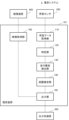
- FIG. 7 is a block diagram illustrating an example of the configuration of an estimation system according to the fourth embodiment of the present disclosure.
- the estimation system 3 of this embodiment includes an estimation device 102, a load sensor 200, an output destination device 300, an imaging device 400, and a microphone 500.
- the load sensor 200, output destination device 300, and imaging device 400 of this embodiment are the same as the load sensor 200, output destination device 300, and imaging device 400 of the third embodiment, respectively.
- the estimation device 102 of this embodiment includes a load data acquisition section 110, a specification section 120, a running abnormality detection section 130, a range estimation section 140, an output section 150, a video acquisition section 160, and a sound data acquisition section 170. and an abnormal sound detection section 180.
- the load data acquisition unit 110, identification unit 120, running abnormality detection unit 130, range estimation unit 140, output unit 150, and video acquisition unit 160 of this embodiment are the This is the same as the load data acquisition unit 110, identification unit 120, running abnormality detection unit 130, range estimation unit 140 output unit 150, and video acquisition unit 160 of the first embodiment.
- the load data acquisition unit 110, identification unit 120, running abnormality detection unit 130, range estimation unit 140, output unit 150, and video acquisition unit 160 of this embodiment are the It performs the same operations as the load data acquisition unit 110, identification unit 120, running abnormality detection unit 130, range estimation unit 140 output unit 150, and video acquisition unit 160 of the first embodiment.
- Microphone 500 measures sound generated in the installation area.
- the microphone 500 transmits measured sound data (hereinafter referred to as sound data) to the sound data acquisition unit 170.
- Microphone 500 may include a plurality of different microphones.
- the sound data acquisition unit 170 acquires sound data of the sound measured by the microphone 500 from the microphone 500.
- the abnormal sound detection unit 180 detects abnormal sounds from the sound data acquired by the sound data acquisition unit 170.
- Abnormal sounds are sounds that meet abnormal sound criteria.
- the abnormal sound standard is, for example, a standard that is appropriately determined in advance so that the sound at the time of a vehicle collision satisfies the standard.
- the abnormal sound detection unit 180 estimates the time when the detected abnormal sound occurred.
- the abnormal sound detection unit 180 detects, for example, a typical period from when a sound occurs until the sound data acquisition unit 170 receives the sound data of the generated sound from the microphone 500, and data at the time when the abnormal sound occurs.
- the time when the detected abnormal sound occurs (hereinafter referred to as abnormal sound generation time) is estimated from the time when the sound data acquisition unit 170 receives the abnormal sound.
- the abnormal sound detection unit 180 When the abnormal sound detection unit 180 detects an abnormal sound, it transmits a notification to the range estimation unit 140.
- This notification may be a notification indicating that an abnormal sound has been detected.
- the abnormal sound detection unit 180 When the abnormal sound detection unit 180 detects an abnormal sound, it sends information on the abnormal sound generation time and sound data measured in a second time range including the abnormal sound generation time to the output unit 150.
- ⁇ Range estimation unit 140 When the range estimating unit 140 receives the above-mentioned notification from the abnormal sound detecting unit 180, the range estimating unit 140 estimates the brake range.
- the output unit 150 of the present embodiment further receives information on the abnormal sound generation time and sound data in a second time range including the abnormal sound generation time from the abnormal sound detection unit 180 when an abnormal sound is detected. .
- the output unit 150 requests the image acquisition unit 160 for images captured during the second time range, and receives from the image acquisition unit 160 the requested images captured during the second time range.
- the output unit 150 outputs the image captured during the second time range to the output destination device 300.
- the output unit 150 may further output the sound data measured in the second time range to the output destination device 300.
- the output unit 150 may further output the abnormal sound generation time to the output destination device 300.
- the output unit 150 further outputs the estimated brake range.
- the video acquisition unit 160 is equipped with a temporary storage device of a size that can store video of a length longer than a predetermined period, and stores the received video data in the temporary storage device for a predetermined period after receiving the video data.
- the length of this predetermined period is, for example, experimentally determined so as to include the above-described first time range and second time range.
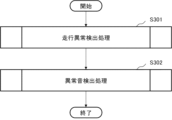
- FIG. 8 is a flowchart illustrating an overall example of the operation of the estimation device 102 according to the fourth embodiment of the present disclosure.
- the estimation device 102 performs a traveling abnormality detection process (step S301).
- the estimation device 102 performs abnormal sound detection processing (step S302).
- the running abnormality detection process and the abnormal sound detection process will be specifically explained later.
- the estimation device 102 may repeat the operation shown in FIG.
- the estimation device 102 may perform the operation in step S301 after step S302.
- the estimation device 102 may perform the operation in step S301 and the operation in step S302 in parallel.
- FIG. 9 is a flowchart illustrating an example of the operation of the driving abnormality detection process of the estimation device 102 according to the fourth embodiment of the present disclosure.
- the operation shown in FIG. 9 is the same as the operation of the estimation device 101 of the third embodiment shown in FIG. 7.
- the estimation device 102 performs the same operation as the estimation device 101 of the third embodiment shown in FIG. 7 .
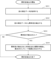
- FIG. 10 is a flowchart illustrating an example of the operation of the abnormal sound detection process of the estimation device 102 according to the fourth embodiment of the present disclosure.
- the sound data acquisition unit 170 acquires sound measurement data from the microphone 500 (step S311).
- the abnormal sound detection unit 180 detects an abnormal sound from the sound measurement data (step S312). If no abnormal sound is detected (NO in step S313), the estimation device 102 ends the operation shown in FIG. 10. If an abnormal sound is detected (YES in step S313), the output unit 150 outputs an image of a period including the time when the abnormal sound was detected and the estimated brake range (step S314). In step S314, the output unit 150 may further output the sound data measured in the second time range. In step S314, the output unit 150 may further output the abnormal sound generation time. The estimation device 102 then ends the operation shown in FIG.
- This embodiment also has the effect of increasing the possibility of obtaining the braking range and images when a traffic accident occurs. This is because, when an abnormal sound is detected, the output unit 150 outputs an image and a brake range for a period including the time when the abnormal sound occurs. If an abnormal sound is detected, a traffic accident may have occurred. The video of the period including the time when the abnormal sound occurred may include the video of the time when a traffic accident occurred.
- the estimation device 10, estimation device 100, estimation device 101, and estimation device 102 according to the embodiments described above are realized by a computer including a memory loaded with a program read from a storage medium and a processor that executes the program. can.
- Estimating device 10, estimating device 100, estimating device 101, and estimating device 102 can also be realized by dedicated hardware.
- Estimating device 10, estimating device 100, estimating device 101, and estimating device 102 can also be realized by a combination of the above-mentioned computer and dedicated hardware.
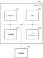
- FIG. 11 is a diagram illustrating an example of a hardware configuration of a computer 1000 that can implement an estimation device according to an embodiment of the present disclosure.
- the computer 1000 includes a processor 1001, a memory 1002, a storage device 1003, and an I/O (Input/Output) interface 1004. Additionally, computer 1000 can access storage medium 1005.
- the memory 1002 and the storage device 1003 are, for example, a RAM (Random Access Memory), a hard disk, or the like.
- the storage medium 1005 is, for example, a storage device such as a RAM or a hard disk, a ROM (Read Only Memory), or a portable storage medium.
- the storage device 1003 may be the storage medium 1005.
- the processor 1001 can read and write data and programs to and from the memory 1002 and the storage device 1003. Processor 1001 can access other devices via I/O interface 1004. Processor 1001 can access storage medium 1005.
- the storage medium 1005 stores a program that causes the computer 1000 to operate as an estimation device according to an embodiment of the present disclosure.
- the processor 1001 loads into the memory 1002 a program stored in the storage medium 1005 that causes the computer 1000 to operate as the estimation device according to the embodiment of the present disclosure. Then, by the processor 1001 executing the program loaded into the memory 1002, the computer 1000 operates as an estimation device according to an embodiment of the present disclosure.
- the load data acquisition unit 110, identification unit 120, running abnormality detection unit 130, range estimation unit 140, output unit 150, video acquisition unit 160, sound data acquisition unit 170, and abnormal sound detection unit 180 are loaded into the memory 1002, for example.
- This can be realized by a processor 1001 that executes a program.
- Some or all of the load data acquisition section 110, identification section 120, running abnormality detection section 130, range estimation section 140, output section 150, video acquisition section 160, sound data acquisition section 170, and abnormal sound detection section 180 can be It can also be realized by a dedicated circuit that realizes the function.
- load data acquisition means for acquiring measurement data of changes in load magnitude measured by a plurality of load sensors embedded in a road surface installation area; Identification means for identifying a vehicle load transition, which is a transition in the position and magnitude of a load due to tires of the same vehicle, from the measurement data; Range estimating means for estimating a braking range in which the vehicle moved with the brakes applied from the identified vehicle load transition; output means for outputting the estimated brake range;
- An estimation device comprising:
- the specifying means specifies a tire load transition, which is a change in a combination of load size and position for each tire, from the measurement data, and among the tire load transitions, the tire load transition due to tires of the same vehicle is determined.
- the estimation device according to supplementary note 1, wherein the combination of is specified as the vehicle load transition.
- Driving abnormality detection means for detecting an abnormality from transition data that is data of at least one of the tire load transition and the vehicle load transition,
- the range estimating means estimates the brake range when the abnormality is detected,
- the estimation device according to supplementary note 2, wherein the output means further outputs a time when the detected abnormality occurred.
- appendix 5 The estimation device according to appendix 3 or 4, wherein the traveling abnormality detection means detects, from the vehicle load transition, movement of the vehicle to a position that satisfies a predetermined abnormal position reference as the abnormality.
- An image acquisition unit that acquires the image from an imaging device that captures an image of the installation area, When the abnormality is detected, the output means further outputs an occurrence time at which the detected abnormality occurred and the image captured during a first time range including the occurrence time. 6.
- the estimation device according to any one of 3 to 5.
- the estimation device according to appendix 6, further outputting the captured video.
- a tire load transition which is a combination of load size and position for each tire, is specified, and among the tire load transitions, a combination of the tire load transitions due to the tires of the same vehicle is determined as described above.
- the estimation method described in Appendix 8 is specified as vehicle load transition.
- Appendix 10 detecting an abnormality from transition data that is at least one of the tire load transition and the vehicle load transition; estimating the brake range when the abnormality is detected; The estimation method according to appendix 9, further comprising outputting a time when the detected abnormality occurred.
- Appendix 11 The estimation method according to appendix 10, wherein a movement of the vehicle that satisfies a predetermined abnormal movement criterion is detected as the abnormality from the vehicle load transition.
- Appendix 12 The estimation method according to appendix 10 or 11, wherein movement of the vehicle to a position that satisfies a predetermined abnormal position criterion is detected as the abnormality based on the vehicle load transition.
- Appendix 14 Obtaining sound data that is data of the sound from a microphone that measures sound in the installation area, Detecting an abnormal sound that meets abnormal sound criteria from the sound data, The abnormal sound generation time at which the detected abnormal sound occurred, the sound data measured during a second time range including the abnormal sound generation time, and the video image captured during the second time range.
- the estimation method described in Appendix 13 further outputs .
- Load data acquisition processing that acquires measurement data of changes in load size measured by a plurality of load sensors embedded in a road surface installation area; From the measurement data, identification processing that identifies a vehicle load transition that is a transition in the position and magnitude of the load due to the tires of the same vehicle; Range estimation processing for estimating a braking range in which the vehicle moved with the brakes applied from the identified vehicle load transition; output processing for outputting the estimated brake range;
- a storage medium that stores a program that causes a computer to execute.
- the identification process specifies, from the measurement data, a tire load transition that is a transition in a combination of load size and position for each tire, and among the tire load transitions, the tire load transition due to tires of the same vehicle is determined.
- Appendix 17 further causing the computer to execute a running abnormality detection process for detecting an abnormality from transition data that is data of at least one of the tire load transition and the vehicle load transition;
- the range estimation process estimates the brake range when the abnormality is detected;
- the storage medium according to appendix 16, wherein the output process further outputs a time when the detected abnormality occurred.
- Appendix 18 The storage medium according to appendix 17, wherein the traveling abnormality detection process detects a movement of the vehicle that satisfies a predetermined abnormal movement criterion from the vehicle load transition as the abnormality.
- Appendix 19 The storage medium according to appendix 17 or 18, wherein the traveling abnormality detection process detects, from the vehicle load transition, movement of the vehicle to a position that satisfies a predetermined abnormal position reference as the abnormality.
- (Additional note 20) further causing the computer to execute a video acquisition process of acquiring the video from an imaging device that captures the video of the installation area;
- the output processing further outputs, when the abnormality is detected, an occurrence time at which the detected abnormality occurred and the video imaged during a first time range including the occurrence time.
- 20. The storage medium according to any one of 17 to 19.
- the output process includes the sound data measured between the abnormal sound generation time at which the detected abnormal sound occurred and a second time range including the abnormal sound generation time, and the sound data measured during the second time range including the abnormal sound generation time.
- Estimation System 2 Estimation System 3
- Estimation System 10 Estimation Device 100 Estimation Device 101 Estimation Device 102 Estimation Device 110 Load Data Acquisition Unit 120 Specification Unit 130 Travel Abnormality Detection Unit 140 Range Estimation Unit 150 Output Unit 160 Video Acquisition Unit 170 Sound Data Acquisition Unit 180 Abnormal sound detection section 200 Load sensor 300 Output destination device 400 Imaging device 500 Microphone 1000 Computer 1001 Processor 1002 Memory 1003 Storage device 1004 I/O interface 1005 Storage medium
Landscapes
- Physics & Mathematics (AREA)
- General Physics & Mathematics (AREA)
- Traffic Control Systems (AREA)
Priority Applications (2)
| Application Number | Priority Date | Filing Date | Title |
|---|---|---|---|
| JP2024505821A JP7743910B2 (ja) | 2022-03-11 | 2022-03-11 | 推定装置、推定方法及びプログラム |
| PCT/JP2022/010942 WO2023170939A1 (ja) | 2022-03-11 | 2022-03-11 | 推定装置、推定方法及び記憶媒体 |
Applications Claiming Priority (1)
| Application Number | Priority Date | Filing Date | Title |
|---|---|---|---|
| PCT/JP2022/010942 WO2023170939A1 (ja) | 2022-03-11 | 2022-03-11 | 推定装置、推定方法及び記憶媒体 |
Publications (1)
| Publication Number | Publication Date |
|---|---|
| WO2023170939A1 true WO2023170939A1 (ja) | 2023-09-14 |
Family
ID=87936480
Family Applications (1)
| Application Number | Title | Priority Date | Filing Date |
|---|---|---|---|
| PCT/JP2022/010942 Ceased WO2023170939A1 (ja) | 2022-03-11 | 2022-03-11 | 推定装置、推定方法及び記憶媒体 |
Country Status (2)
| Country | Link |
|---|---|
| JP (1) | JP7743910B2 (https=) |
| WO (1) | WO2023170939A1 (https=) |
Citations (3)
| Publication number | Priority date | Publication date | Assignee | Title |
|---|---|---|---|---|
| JPS645224Y2 (https=) * | 1981-05-01 | 1989-02-09 | ||
| JPH11321597A (ja) * | 1998-05-15 | 1999-11-24 | Fujitsu Ten Ltd | 車両走行制御装置および走行路 |
| CN111210630A (zh) * | 2020-01-14 | 2020-05-29 | 长安大学 | 一种基于压电路面的车辆交通状态自感知预警系统及方法 |
Family Cites Families (2)
| Publication number | Priority date | Publication date | Assignee | Title |
|---|---|---|---|---|
| JP2004133660A (ja) * | 2002-10-10 | 2004-04-30 | Mitsubishi Heavy Ind Ltd | 交通制御システム |
| WO2017153979A1 (en) * | 2016-03-06 | 2017-09-14 | Foresight Automotive Ltd. | Running vehicle alerting system and method |
-
2022
- 2022-03-11 WO PCT/JP2022/010942 patent/WO2023170939A1/ja not_active Ceased
- 2022-03-11 JP JP2024505821A patent/JP7743910B2/ja active Active
Patent Citations (3)
| Publication number | Priority date | Publication date | Assignee | Title |
|---|---|---|---|---|
| JPS645224Y2 (https=) * | 1981-05-01 | 1989-02-09 | ||
| JPH11321597A (ja) * | 1998-05-15 | 1999-11-24 | Fujitsu Ten Ltd | 車両走行制御装置および走行路 |
| CN111210630A (zh) * | 2020-01-14 | 2020-05-29 | 长安大学 | 一种基于压电路面的车辆交通状态自感知预警系统及方法 |
Also Published As
| Publication number | Publication date |
|---|---|
| JPWO2023170939A1 (https=) | 2023-09-14 |
| JP7743910B2 (ja) | 2025-09-25 |
Similar Documents
| Publication | Publication Date | Title |
|---|---|---|
| US9616890B2 (en) | ACC and AM braking range variable based on internal and external factors | |
| CN103718061B (zh) | 使用radar和视频的改进的驾驶员辅助系统 | |
| JP7081423B2 (ja) | 情報処理システム | |
| CN103350698B (zh) | 用于运行车辆的方法和设备 | |
| US10077050B2 (en) | Automated driving system for evaluating lane cut-out and method of using the same | |
| JP4207088B2 (ja) | 車両走行推定装置 | |
| US8447484B2 (en) | Branch-lane entry judging system | |
| CN108074401B (zh) | 一种车辆加塞行为判别方法及装置 | |
| US8543309B2 (en) | ACC and AM braking range variable based on lateral and longitudinal position of forward vehicle and curvature of road | |
| US20220219684A1 (en) | Vehicle control device | |
| CN101559753A (zh) | 基于单目机器视觉的汽车主动安全系统及其控制方法 | |
| CN118514718A (zh) | 智能驾驶决策方法、装置、存储介质及电子设备 | |
| JP5903985B2 (ja) | 渋滞誘因運転行動評価方法 | |
| JP7743910B2 (ja) | 推定装置、推定方法及びプログラム | |
| CN112926545A (zh) | 车载急刹车危险行为识别系统、控制方法及存储介质 | |
| JP7711660B2 (ja) | 情報処理システム及び情報処理システムの処理方法 | |
| JP2016045915A (ja) | 一時不停止警報装置 | |
| JP6582746B2 (ja) | 監視判定装置および監視判定方法 | |
| KR20240054435A (ko) | 차량용 충돌 회피 장치 및 방법 | |
| JP2023179141A5 (https=) | ||
| JP2025028925A (ja) | 検出装置、検出方法、検出プログラム及び記録媒体 | |
| JP2024088292A (ja) | 車載装置、運転支援装置、運転支援システム、および前方車両の荷崩れ判定方法 | |
| CN121938220A (zh) | 系统 | |
| JP2025184063A (ja) | 情報処理装置、情報処理システム、車載装置及び情報処理方法 | |
| CN119611335A (zh) | 车辆控制方法、电子设备及车辆 |
Legal Events
| Date | Code | Title | Description |
|---|---|---|---|
| 121 | Ep: the epo has been informed by wipo that ep was designated in this application |
Ref document number: 22930920 Country of ref document: EP Kind code of ref document: A1 |
|
| ENP | Entry into the national phase |
Ref document number: 2024505821 Country of ref document: JP Kind code of ref document: A |
|
| NENP | Non-entry into the national phase |
Ref country code: DE |
|
| 122 | Ep: pct application non-entry in european phase |
Ref document number: 22930920 Country of ref document: EP Kind code of ref document: A1 |