WO2023170809A1 - 基地局装置および端末装置 - Google Patents
基地局装置および端末装置 Download PDFInfo
- Publication number
- WO2023170809A1 WO2023170809A1 PCT/JP2022/010217 JP2022010217W WO2023170809A1 WO 2023170809 A1 WO2023170809 A1 WO 2023170809A1 JP 2022010217 W JP2022010217 W JP 2022010217W WO 2023170809 A1 WO2023170809 A1 WO 2023170809A1
- Authority
- WO
- WIPO (PCT)
- Prior art keywords
- control information
- base station
- terminal
- antenna ports
- arrangement
- Prior art date
- Legal status (The legal status is an assumption and is not a legal conclusion. Google has not performed a legal analysis and makes no representation as to the accuracy of the status listed.)
- Ceased
Links
Images





Classifications
-
- H—ELECTRICITY
- H04—ELECTRIC COMMUNICATION TECHNIQUE
- H04W—WIRELESS COMMUNICATION NETWORKS
- H04W16/00—Network planning, e.g. coverage or traffic planning tools; Network deployment, e.g. resource partitioning or cells structures
- H04W16/24—Cell structures
- H04W16/28—Cell structures using beam steering
Definitions
- the present invention relates to a base station device and a terminal device used in a mobile communication system.
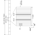
- FIG. 1 shows an example of a method for reducing power consumption of a base station in the spatial domain.
- the base station gNB
- the base station can change the number of wireless transceiver circuits and multiple antennas used depending on the traffic. Specifically, when the traffic between the base station and the terminal (UE) decreases, the base station controls one or more radio transceiver circuits to be turned off and also reduces the number of multiple antennas used. do. In other words, dynamic antenna adaptation according to traffic is realized. As a result, power consumption of the base station is reduced.
- this method is described in, for example, Non-Patent Document 1.
- the base station sets parameters for transmitting wireless signals to the terminal based on the state of the channel between the base station and the terminal. Specifically, the base station notifies the terminal of the antenna arrangement of the base station. The terminal estimates the state of the channel between the base station and the terminal using reference signals transmitted from the base station. At this time, the terminal creates channel state information (CSI) representing the state of the channel based on the antenna arrangement of the base station. This channel state information is transmitted from the terminal to the base station. The base station then sets parameters for transmitting wireless signals based on the channel state information. That is, CSI feedback realizes downlink transmission according to channel conditions.
- CSI channel state information
- An object of one aspect of the present invention is to provide a method of notifying a terminal of a change in the antenna arrangement of a base station device without delay.
- a base station device can change the number of antenna ports used to transmit wireless signals.
- This base station device includes a plurality of antenna ports, a control information generation unit that generates control information related to the arrangement of a transmission antenna port used for transmitting a wireless signal among the plurality of antenna ports, and A control information transmitter that transmits information to the terminal.
- the control information generation unit generates first control information representing a first arrangement of the transmitting antenna ports, and second control information representing a second arrangement of the transmitting antenna ports that is different from the first arrangement. generate.
- the control information transmitter transmits the first control information to the terminal using a first method, and then transmits the second control information to the terminal using a second method different from the first method. .
- a change in antenna arrangement of a base station device can be notified to a terminal without delay.
- FIG. 2 is a diagram illustrating an example of a method for reducing power consumption of a base station in the spatial domain.
- FIG. 1 is a diagram showing an example of a base station device according to an embodiment of the present invention. It is a figure showing an example of composition of an antenna.
- FIG. 6 is a diagram illustrating an example of a change in antenna arrangement when the number of wireless transceivers operating in a base station is reduced.
- FIG. 3 is a diagram showing an example of CSI feedback.
- FIG. 3 is a diagram illustrating an example of a CSI feedback sequence.
- FIG. 6 is a diagram illustrating an example of a CSI feedback sequence when the antenna arrangement changes.
- FIG. 3 is a diagram showing an example of a CSI feedback sequence according to an embodiment of the present invention.
- FIG. 1 is a diagram showing an example of a base station device according to an embodiment of the present invention. It is a figure showing an example of composition of an antenna.
- FIG. 6 is a diagram illustrating an
- FIG. 3 is a diagram illustrating an example of resources for transmitting DCI.
- 1 is a diagram showing an example of a terminal device according to an embodiment of the present invention.
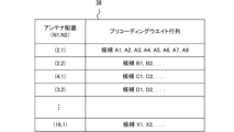
- FIG. 3 is a diagram showing an example of a codebook.
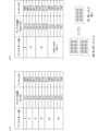
- FIG. 3 is a diagram illustrating an example of antenna arrangement supported by a base station.
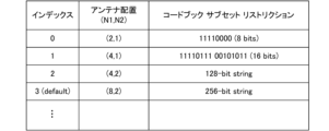
- FIG. 3 is a diagram illustrating an example of a codebook subset restriction list.
- FIG. 3 is a diagram illustrating an example of a description related to a CSI report.
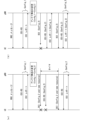
- FIG. 7 is a diagram illustrating an example of a CSI feedback sequence according to a third embodiment.
- FIG. 7 is a diagram showing an example of a CSI feedback sequence according to a fourth embodiment.
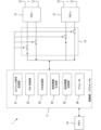
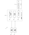
- FIG. 2 shows an example of a base station device according to an embodiment of the present invention.
- the base station device 1 according to the embodiment of the present invention includes a control unit 11, a plurality of radio transceivers (TRX_1 to TRX_n) 12, a switch circuit 13, and a memory 14.
- the base station device 1 is, for example, a gNB, although it is not particularly limited.
- the base station device 1 may include other circuits, elements, and functions not shown in FIG. 2.
- a base station device may be simply referred to as a "base station.”
- the control unit 11 connects to the core network via an interface. Further, the control unit 11 controls wireless communication with one or more terminals (UE) located within the cell of the base station 1. At this time, the control unit 11 can dynamically control the number of radio transceivers 12 used by the base station 1 according to the traffic within the cell. Note that the functions of the control section 11 will be explained later.
- Each wireless transceiver 12 includes one or more antenna elements. Then, the wireless transceiver 12 uses the antenna element to transmit a downlink signal generated by the control unit 11 to the terminal, and receives an uplink signal transmitted from the terminal.
- the downlink signal includes a data signal and a control signal. Further, the downlink signal is transmitted via, for example, a PDSCH (Physical Downlink Shared Channel) or a PDCCH (Physical Downlink Control Channel).
- Uplink signals include data signals and control signals. Further, the uplink signal is transmitted via, for example, a PUSCH (Physical Uplink Shared Channel) or a PUCCH (Physical Uplink Control Channel).
- the switch circuit 13 controls the wireless transceiver 12 to turn on or off according to instructions from the control unit 11. For example, when there is a lot of traffic within the cell of the base station 1, the switch circuit 13 may control all the radio transceivers 12 to be in the on state according to instructions from the control unit 11. Furthermore, when the traffic decreases, the switch circuit 13 may control some of the wireless transceivers 12 to turn off according to instructions from the control unit 11.
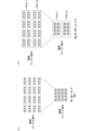
- FIG. 3 shows a configuration example of an antenna included in the base station 1.
- each wireless transceiver 12 includes three antenna elements. Note that in FIG. 3, an x mark represents one antenna element. Furthermore, each antenna element has two ports in order to realize polarization multiplexing.
- the base station 1 includes one antenna panel. 4 ⁇ 4 antenna circuits are mounted within this antenna panel. Each antenna circuit is connected to a corresponding wireless transceiver 12, respectively. That is, in this example, the base station 1 includes 16 wireless transceivers 12.
- the antenna arrangement of the base station 1 is expressed using logical antenna elements as necessary.
- an antenna circuit connected to one radio transceiver 12 is represented as one logical antenna element. Therefore, in this case, the base station 1 will be equipped with 16 logical antenna elements.
- the logical antenna element is sometimes called an antenna port.
- the antenna arrangement is represented by three parameters Ng, N1, and N2.
- Ng represents the number of antenna panels.
- N1 represents the number of antenna elements arranged in the horizontal direction.
- N2 represents the number of antenna elements arranged in the vertical direction.
- N1 represents the number of antenna ports arranged in the horizontal direction.
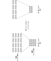
- FIG. 4 shows an example of a change in antenna arrangement when the number of wireless transceivers 12 operating in the base station 1 is reduced.
- the base station 1 has an antenna shown in FIG. 3(a). Then, eight of the 16 wireless transceivers 12 are controlled to be in the off state. As a result, the antenna arrangement of base station 1 is changed from (1, 4, 4) to (1, 4, 2).
- the base station 1 can dynamically control the number of radio transceivers 12 used by the base station 1, depending on the traffic within the cell.
- the antenna arrangement of the base station 1 changes.
- the base station 1 notifies the terminal of the change in antenna arrangement.
- FIG. 5 shows an example of CSI feedback.
- base station (gNB) 1 performs precoding transmission.
- precoding transmission the directivity of a transmission signal is controlled by multiplying a combination of a data sequence and a transmission antenna by a precoding weight.
- base station 1 needs to recognize the state of the channel between base station 1 and the terminal. Therefore, the base station 1 recognizes the channel state by CSI feedback.
- the base station 1 transmits a CSI reference signal to the terminal for each antenna.
- the terminal estimates the channel state based on the received CSI reference signal.
- the terminal includes a codebook.
- the codebook stores predetermined precoding weight matrix candidates.
- the terminal selects a suitable precoding weight matrix from the codebook according to the estimated channel state. Note that the selected precoding weight matrix is identified using a PMI (Precoding Matrix Indicator).
- the terminal creates a CSI report representing the state of the channel.
- the CSI report includes the above-mentioned PMI. Further, the CSI report includes a CQI (Channel Quality Indicator) and an RI (Rank Indicator).
- CQI represents downlink reception quality and is used by base station 1 to select a modulation scheme and code.
- the RI specifies the preferred number of transmission streams. The terminal then transmits the CSI report to the base station 1.
- the base station 1 controls signal transmission to the terminal based on the CSI report. That is, CSI feedback is realized. Specifically, base station 1 performs precoding according to PMI, selects a modulation scheme and code based on CQI, and determines the number of transmission streams based on RI.
- FIG. 6 shows an example of a CSI feedback sequence.
- the base station (gNB) 1 transmits an RRC (Radio Resource Control) message to the terminal (UE).
- This RRC message specifies the configuration of the CSI report.
- this RRC message includes information representing the antenna arrangement of the base station 1. The antenna arrangement is expressed using, for example, the three parameters Ng, N1, and N2 described with reference to FIGS. 3 and 4.
- this RRC message includes resource information representing resources for the terminal to receive a CSI reference signal (CSI-RS) and resources for the terminal to transmit a CSI report.
- the resource information specifies, for example, time and frequency.
- this RRC message corresponds to a trigger that instructs the terminal to create a CSI report.
- the RRC message may be an RRC reconfiguration message, an RRC stop message, or an RRC release message.
- the RRC message may specify multiple sets of parameters Ng, N1, and N2 as antenna placement candidates.
- the RRC message may also specify resource candidates for CSI reference signals and CSI reports.
- the base station 1 transmits a MAC Control Element (MAC-CE) to the terminal following the RRC message.
- MAC-CE MAC Control Element
- This MAC-CE specifies one set of parameters corresponding to the actual antenna arrangement from among multiple sets of parameters Ng, N1, and N2.
- this MAC-CE specifies a resource to actually be used from among the resource candidates. In this case, this MAC-CE corresponds to a trigger that instructs the terminal to create a CSI report.
- the base station 1 transmits a CSI reference signal to the terminal using the PDSCH.
- the CSI reference signal is used by the terminal to create a CSI report, as described with reference to FIG. Note that the resources (time and frequency) for transmitting the CSI reference signal are notified from the base station 1 to the terminal by an RRC message or MAC-CE. Therefore, the terminal can receive the CSI reference signal.
- the terminal creates a CSI report based on the CSI reference signal received from the base station 1.
- the CSI report includes PMI, CQI, and RI, as described above.
- the terminal then transmits the created CSI report to the base station 1.
- the base station 1 determines downlink parameters based on the CSI report. Specifically, the precoding weight, modulation method, code, number of transmission streams, etc. are determined based on the CSI report. Then, the base station 1 transmits downlink data to the terminal according to the determined parameters.
- the terminal creates a CSI report and transmits it to the base station 1.
- the terminal creates a CSI report based on the antenna arrangement of the base station 1. Therefore, when the terminal does not correctly recognize the antenna arrangement of the base station 1, inappropriate PMI, CQI, or RI will be notified to the base station 1. In this case, the quality of the downlink may deteriorate.
- FIG. 7 shows an example of a CSI feedback sequence when the antenna arrangement changes. Note that the initial state of the antenna arrangement is notified from the base station 1 to the terminal by an RRC message or MAC-CE shown in FIG.
- FIG. 7(a) shows a sequence in which periodic CSI reporting is performed.
- the CSI report is initiated by the RRC message. After this, CSI reporting is performed repeatedly until an RRC message indicating reconfiguration is sent. Then, when the antenna arrangement of the base station 1 changes, an RRC message representing the new antenna arrangement is transmitted from the base station 1 to the terminal. This allows the terminal to recognize the latest antenna arrangement.
- FIG. 7(b) shows a sequence in which a semi-persistent CSI report is performed.
- CSI reporting is started by MAC-CE (activation). Thereafter, CSI reporting is repeatedly executed until a MAC-CE (deactivation) is sent to invalidate the settings. Then, when the antenna arrangement of base station 1 changes, base station 1 sends a MAC-CE (deactivation) to the terminal to disable the settings related to the previous antenna arrangement, and activates the settings related to the new antenna arrangement. MAC-CE (activation) to be sent to the terminal. This allows the terminal to recognize the latest antenna arrangement.
- FIG. 8 shows an example of a CSI feedback sequence according to an embodiment of the present invention. Note that FIG. 8(a) shows a sequence in which a periodic CSI report is performed, and FIG. 8(b) shows a sequence in which a semi-persistent CSI report is performed.
- the method of notifying the terminal of the initial state of the antenna arrangement of the base station 1 is substantially the same in FIGS. 7 and 8. That is, the initial state of the antenna arrangement of the base station 1 is notified to the terminal by an RRC message or MAC-CE. Note that the terminal receives three parameters Ng, N1, and N2 representing the antenna arrangement through this notification. Therefore, the terminal can recognize the number of antenna panels of the base station 1.
- DCI downlink control information
- the base station 1 uses downlink control information (DCI) to notify the terminal of the changed antenna arrangement.
- DCI can use existing formats (Format0_0, Format0_1, Format0_2). In this case, new fields are added to the existing format. Information representing the changed antenna arrangement is then written into a new field.
- a new DCI format may be defined to notify the terminal of the changed antenna arrangement.
- the DCI does not need to include resource information representing resources for CSI reference signals and CSI reports.
- the terminal receives the CSI reference signal from the PDSCH notified by the RRC message, and also transmits the CSI report on the PUSCH or PUCCH notified by the RRC message.
- the terminal receives the CSI reference signal from the PDSCH specified by the MAC-CE, and also transmits the CSI report on the PUSCH or PUCCH specified by the MAC-CE.
- the base station 1 may reconfigure resources for the CSI reference signal and CSI report.
- the DCI includes resource information representing resources for CSI reference signals and CSI reporting. Then, the terminal receives a CSI reference signal from the PDSCH notified by the DCI, and also transmits a CSI report on the PUSCH or PUCCH notified by the DCI.
- FIG. 9 shows an example of resources for transmitting DCI.
- radio frames are transmitted between the base station 1 and the terminal.
- the length of the radio frame is 10 msec.
- a radio frame is composed of 10 subframes. Therefore, the length of the subframe is 1 msec.
- Each subframe is composed of one or more slots. For example, when the subcarrier frequency spacing (SCS) is 15 kHz, a subframe consists of one slot. Furthermore, when the subcarrier frequency interval is 30 kHz, a subframe is composed of two slots. Each slot consists of 14 symbols in the time domain. Note that FIG. 9 shows a case where the subcarrier frequency interval is 15 kHz.
- SCS subcarrier frequency spacing
- Each frame includes resources for transmitting DCI.
- DCI is transmitted using the first symbol and the second symbol.
- the CSI reference signal is transmitted using the fifth symbol and the ninth symbol.
- the DCI is stored in each slot constituting a radio frame and transmitted from the base station 1 to the terminal. Therefore, when changing the antenna arrangement, the base station 1 can notify the terminal of the changed antenna arrangement without delay.
- the control unit 11 includes an uplink signal processing unit 21, a TRX control unit 22, an RS transmission unit 23, a control information generation unit 24, a control information transmission unit 25, and a precoder 26. Note that the control unit 11 may include other functions not shown in FIG. 2.
- the uplink signal processing unit 21 processes uplink signals transmitted from the terminal.
- the uplink signal processing unit 21 can receive a CSI report transmitted from a terminal.
- the CSI report represents the state of the channel between the base station 1 and the terminal, and includes PMI, CQI, and RI.
- the TRX control unit 22 determines the number of wireless transceivers 12 in the on state based on the traffic within the cell of the base station 1. That is, when traffic is low, in order to reduce power consumption of the base station 1, the TRX control unit 22 turns off one or more radio transceivers 12 to reduce the number of radio transceivers 12 in the on state. .
- the TRX control unit 22 controls the number of wireless transceivers 12 in the on state by controlling the switch circuit 13.
- the antenna element connected to the off-state wireless transceiver 12 is not used in communication with the terminal. Therefore, controlling the number of wireless transceivers 12 in the on state changes the number and arrangement of antenna elements used to transmit wireless signals. Note that an antenna element used to transmit a wireless signal is sometimes referred to as a "transmission antenna element.”
- the RS transmitter 23 transmits a CSI reference signal to the terminal.
- CSI reference signals are transmitted with known power and are used by terminals to detect channel conditions. Note that the CSI reference signal is transmitted using a predetermined symbol of each slot, for example, as shown in FIG.
- the control information generation unit 24 generates control information to be transmitted to the terminal.
- control information related to CSI feedback will be described.
- the control information includes information transmitted by the RRC message and information transmitted by the DCI.
- the initial setting information (first control information) transmitted by the RRC message includes the following information.
- Information representing the initial state of antenna arrangement (2)
- Information representing downlink resources for transmitting CSI reference signals (3)
- Information representing uplink resources for transmitting CSI reports includes the following information.
- the change information (second control information) transmitted by the DCI includes the following information. However, the information transmitted by the DCI does not have to include the following (2) and (3).
- Information representing the changed antenna arrangement (2) Information representing downlink resources for transmitting CSI reference signals (3) Information representing uplink resources for transmitting CSI reports
- the initial state of the antenna arrangement is determined in advance as, for example, default information. Additionally, as the number of wireless transceivers 12 in the on state changes, the number and arrangement of antenna elements used to transmit wireless signals also change. That is, the control information generation unit 24 determines a new antenna arrangement based on the number of wireless transceivers 12 in the on state.
- the control information includes the RRC message, information transmitted by the MAC-CE, and information transmitted by the DCI.
- the initial setting information (first control information) transmitted by the RRC message and MAC-CE includes the following information.
- Information representing antenna placement candidates (2) Information specifying the initial state antenna placement from antenna placement candidates (3) Information representing downlink resources for transmitting CSI reference signals (4) Information representing uplink resources for transmitting CSI reports.
- the change information (second control information) transmitted by the DCI includes the following information. However, the information transmitted by the DCI does not have to include the following (2) and (3).
- Information specifying the changed antenna arrangement from antenna arrangement candidates (2) Information representing downlink resources for transmitting CSI reference signals (3) Information indicating uplink resources for transmitting CSI reports Information representing the resource
- the control information transmitter 25 transmits the control information generated by the control information generator 24 to the terminal. Specifically, in the sequence shown in FIG. 8A, the control information transmitter 25 transmits initial setting information to the terminal using an RRC message, and transmits change information to the terminal using DCI. Furthermore, in the sequence shown in FIG. 8(b), the control information transmitting unit 25 transmits initial setting information to the terminal using the RRC message and MAC-CE, and transmits change information to the terminal using DCI. .
- the precoder 26 controls the directivity of the signal transmitted to the terminal based on the CSI report received from the terminal.
- precoder 26 multiplies the combination of data sequence and transmit antenna by a precoding weight matrix based on the PMI included in the CSI report.
- the control unit 11 that provides the above-mentioned functions is realized by, for example, a processor.
- the processor executes the control program stored in the memory 14 to control the uplink signal processing section 21, the TRX control section 22, the RS transmission section 23, the control information generation section 24, the control information transmission section 25, and provides the functions of the precoder 26.
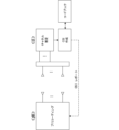
- FIG. 10 shows an example of a terminal device according to an embodiment of the present invention.
- the terminal device 3 according to the embodiment of the present invention includes a wireless receiving section 31, a wireless transmitting section 32, a control section 33, and a memory 37.
- the terminal device 3 is, for example, a UE (User Equipment).
- the terminal device 3 may include other circuits, elements, and functions not shown in FIG.
- a terminal device may be simply referred to as a "terminal.”
- the radio receiving unit 31 receives a downlink signal transmitted from the base station 1. Downlink signals include data signals, control signals, and reference signals.
- the wireless transmitter 32 transmits an uplink signal to the base station 1.
- Uplink signals include data signals, control signals, and reference signals.
- the control unit 33 includes a downlink signal processing unit 34, a channel estimation unit 35, and a CSI generation unit 36. Note that the control unit 33 may include other functions not shown in FIG.
- the downlink signal processing unit 34 processes downlink signals transmitted from the base station 1.
- the downlink signal processing unit 34 can process RRC messages, MAC-CE, and DCI. Specifically, the downlink signal processing unit 34 determines the antenna arrangement of the base station 1, the resources allocated to the CSI reference signal, and the resources allocated to the CSI report based on the RRC message (and MAC-CE). To detect. Furthermore, when the antenna arrangement changes in the base station 1, the downlink signal processing unit 34 detects the new antenna arrangement based on the DCI.
- the channel estimation unit 35 estimates the state of the channel between the base station 1 and the terminal 3 based on the CSI reference signal. For example, attenuation, phase rotation, delay, etc. occurring in the channel are estimated.
- the CSI generation unit 36 generates a CSI report based on the channel state estimated by the channel estimation unit 35.
- the CSI report includes PMI, CQI, and RI, as described above.
- PMI represents an optimal precoding weight matrix selected from codebook 38 stored in memory 37.
- FIG. 11 shows an example of the codebook 38.
- the codebook 38 stores candidates for precoding weight matrices used by the precoder 26 of the base station 1.
- Candidates for the precoding weight matrix are created in advance by simulation or measurement.
- the terminal 3 transmits a CSI report including PMI, CQI, and RI to the base station 1. Then, the base station 1 controls the downlink based on the CSI report, as described above. For example, the precoder 26 controls downlink directivity using a precoding weight matrix specified by the PMI notified from the terminal 3.
- the control unit 33 that provides the above-mentioned functions is realized by, for example, a processor.
- the processor provides the functions of the downlink signal processing unit 34, channel estimation unit 35, and CSI generation unit 36 by executing the control program stored in the memory 37.
- the CSI feedback sequence in the first embodiment is as shown in FIG. That is, as shown in FIG. 8(a), the base station (gNB) 1 notifies the terminal (UE) 3 of the initial state of the antenna arrangement using an RRC message.
- the initial state of the antenna arrangement is notified using the RRC message and MAC-CE. Note that by notification of the initial state of the antenna arrangement, the terminal 3 can detect the number of antenna panels (that is, whether it is a single panel or a multi-panel). After this, when the antenna arrangement of base station 1 changes, base station 1 notifies terminal 3 of the new antenna arrangement using DCI.
- FIG. 12 shows an example of antenna arrangement supported by the base station 1.
- FIG. 12(a) shows a case in which the base station 1 includes one antenna panel
- FIG. 12(b) shows a case in which the base station 1 includes a plurality of antenna panels.
- the number of CSI antenna ports represents the number of logical antenna ports that transmit CSI reference signals.
- the antenna arrangement is represented by a combination of the number N1 of antenna elements arranged in the horizontal direction and the number N2 of antenna elements arranged in the vertical direction. Further, the antenna arrangement is represented by a combination of the number N1 of antenna ports arranged in the horizontal direction and the number N2 of antenna ports arranged in the vertical direction.
- the antenna arrangement can be represented by a 4-bit index.
- 13 antenna arrangement patterns are represented by "0000" to "1100".
- the antenna arrangement is expressed using a 4-bit index, but the first embodiment is not limited to this configuration. That is, the antenna arrangement may be represented by an index of 5 bits or more.
- the terminal 3 when the antenna arrangement of the base station 1 changes, information representing the new antenna arrangement is notified from the base station 1 to the terminal 3 using DCI.
- the DCI is stored and transmitted within each slot constituting a radio frame. Therefore, the terminal 3 can detect a change in the antenna arrangement of the base station 1 without delay. As a result, correct channel state information is fed back to the base station 1, so communication quality does not deteriorate even when the antenna arrangement is changed.
- the CSI feedback sequence in the second embodiment is as shown in FIG. That is, the base station (gNB) 1 notifies the terminal (UE) 3 of antenna placement candidates and the initial state of the antenna placement using the RRC message (and MAC-CE). Thereafter, when the antenna arrangement of the base station 1 changes, the base station 1 uses the DCI to notify the terminal 3 of the identification index of the new antenna arrangement.
- FIG. 13 shows an example of a codebook subset restriction list.
- the codebook subset restriction list represents, for each antenna arrangement of the base station 1, a weight matrix that can be used by the base station 1 or a weight matrix that cannot be used by the base station 1.
- Each bit of restriction information corresponds to a weight matrix candidate stored in codebook 38. That is, the first bit of the restriction information corresponds to the weight matrix candidate A1, and the eighth bit of the restriction information corresponds to the weight matrix candidate A8.
- each antenna arrangement may be identified by an index.
- the base station 1 transmits the codebook subset restriction list shown in FIG. 13 to the terminal 3 using an RRC message.
- default information representing the initial state of the antenna arrangement is set for the codebook subset restriction list.
- the terminal 3 is notified of the initial state of the antenna arrangement by the MAC-CE following the RRC message.
- the terminal 3 stores the codebook subset restriction list acquired from the base station 1 in the memory 37.
- the base station 1 uses the DCI to transmit an index that identifies the new antenna arrangement to the terminal 3. Then, by searching the codebook subset restriction list using the received index, the terminal 3 recognizes the new antenna arrangement and acquires restriction information corresponding to the new antenna arrangement. Thereafter, when the terminal 3 receives the CSI reference signal, it selects a weight matrix within the range specified by the restriction information.
- the base station 1 notifies the terminal 3 of the index "0".
- FIG. 14 shows an example of a description related to a CSI report.
- a description related to a codebook (CodebookConfig) is provided in a description related to a CSI report (CSI-ReportConfig).
- CodebookSubsetRestriction is set in CodebookConfig. Note that this description is transmitted from the base station 1 to the terminal 3 using an RRC message.
- a plurality of processing patterns are used to control the processing of the terminal 3 according to the antenna arrangement of the base station 1. is notified from the base station 1 to the terminal 3. Then, when the antenna arrangement of the base station 1 changes, an index representing the new antenna arrangement is notified from the base station 1 to the terminal 3 using the DCI. Furthermore, the terminal 3 creates a CSI report using a processing pattern corresponding to the notified index and transmits it to the base station 1. Therefore, even when changing the antenna arrangement, the terminal 3 can create the CSI report requested by the base station 1 without delay.
- FIG. 15 shows an example of a CSI feedback sequence according to the third embodiment. Also in the third embodiment, when the antenna arrangement of the base station 1 changes, DCI including information representing the new antenna arrangement is transmitted from the base station 1 to the terminal 3. Then, the terminal 3 creates a CSI report based on the new antenna arrangement and transmits it to the base station 1.
- the terminal 3 transmits an ACK/NACK signal to the base station 1 indicating whether or not the DCI was correctly received.
- the terminal 3 transmits an ACK signal to the base station 1 when information representing the antenna arrangement can be acquired from a predetermined area in the received DCI.
- Terminal 3 transmits a NACK signal to base station 1.
- the base station 1 Upon receiving the ACK signal from the terminal 3, the base station 1 transmits a CSI reference signal to the terminal 3, as shown in FIG. 15(a). After that, the base station 1 waits for a CSI report transmitted from the terminal 3. On the other hand, upon receiving the NACK signal from the terminal 3, the base station 1 retransmits the DCI including information representing the antenna arrangement to the terminal 3, as shown in FIG. 15(b). This retransmission procedure is realized by, for example, HARQ (Hybrid automatic repeat request). In this way, according to the third embodiment, the terminal 3 can reliably recognize the change in the antenna arrangement of the base station 1, and therefore can create a highly accurate CSI report.
- HARQ Hybrid automatic repeat request
- FIG. 16 shows an example of a CSI feedback sequence according to the fourth embodiment. Also in the fourth embodiment, when the antenna arrangement of the base station 1 changes, DCI including information representing the new antenna arrangement is transmitted from the base station 1 to the terminal 3. However, in this embodiment, when the antenna arrangement of base station 1 changes from Config_1 to Config_2, terminal 3 cannot receive DCI.
- the DCI includes information representing the CSI reference signal resource in addition to information representing the changed antenna arrangement.
- terminal 3 cannot receive this DCI.
- the base station 1 starts a timer when transmitting the DCI. Then, the base station 1 transmits the CSI reference signal to the terminal 3 using the resource notified using the DCI.
- the terminal 3 since the terminal 3 has not received the DCI, it does not recognize the resource of the CSI reference signal. That is, the terminal 3 cannot receive the CSI reference signal. Therefore, since the terminal 3 does not create a CSI report, the base station 1 cannot receive the CSI report.
- the base station 1 determines that the terminal 3 has not received the DCI. Then, the base station 1 retransmits the DCI. Here, it is assumed that the terminal 3 receives this DCI. In this case, the terminal 3 can receive subsequent CSI reference signals. Therefore, the terminal 3 creates a CSI report, and the base station 1 receives the CSI report.
- the DCI includes information representing the changed antenna arrangement, but does not include information representing the resources of the CSI reference signal. That is, the CSI reference signal is transmitted according to the initial settings. Then, the terminal 3 cannot receive the DCI, similar to the case shown in FIG. 16(a).
- the base station 1 transmits the CSI reference signal to the terminal 3 based on the changed antenna arrangement.
- the terminal 3 can receive this CSI reference signal. Therefore, the terminal 3 creates a CSI report.
- the terminal 3 since the terminal 3 does not receive the DCI, it does not recognize that the antenna arrangement has changed. Therefore, the terminal 3 creates a CSI report corresponding to the antenna arrangement before the change.
- the antenna arrangement of the base station 1 has changed from Config_1 to Config_2, the terminal 3 creates a CSI report for Config_1.
- the base station 1 receives an incorrect CSI report.
- the bit length of the CSI report depends on the antenna arrangement of the base station 1. Therefore, the base station 1 can determine whether an appropriate CSI report has been created in the terminal 3 based on the bit length of the received CSI report. In this example, base station 1 determines that terminal 3 has created an inappropriate CSI report. Therefore, the base station 1 executes the DCI retransmission procedure. In this manner, also in the fourth embodiment, the terminal 3 can reliably recognize the change in the antenna arrangement of the base station 1, and therefore can create a highly accurate CSI report.
- the base station 1 determines that an inappropriate CSI report has been created in the terminal 3. In this case, the base station 1 may perform a DCI retransmission procedure.
- Base station device 3 Terminal device 11
- Control section 12 Wireless transceiver 21
- Uplink signal processing section 22 TRX control section 23
- RS transmission section 24 Control information generation section 25
- Control information transmission section 26 Precoder 33
- Control section 35 Channel estimation section 36
- CSI generation section 38 code book
Landscapes
- Engineering & Computer Science (AREA)
- Computer Networks & Wireless Communication (AREA)
- Signal Processing (AREA)
- Mobile Radio Communication Systems (AREA)
Abstract
基地局装置のアンテナ配置の変更を遅滞なく端末に通知することが可能である。基地局装置は、無線信号を送信するために使用するアンテナポートの個数を変更可能である。基地局装置は、複数のアンテナポートと、複数のアンテナポートのうちで無線信号を送信するために使用される送信アンテナポートの配置に係わる制御情報を生成する制御情報生成部と、制御情報を端末に送信する制御情報送信部と、を備える。制御情報生成部は、送信アンテナポートの第1の配置を表す第1の制御情報、および、第1の配置と異なる送信アンテナポートの第2の配置を表す第2の制御情報を生成する。制御情報送信部は、第1の方法で第1の制御情報を端末に送信した後に、第1の方法と異なる第2の方法で第2の制御情報を端末に送信する。
Description
本発明は、モバイル通信システムにおいて使用される基地局装置および端末装置に係わる。
モバイル通信システムにおいて通信機器の消費電力の削減が要求されている。例えば、RAN(Radio Access Network)#94-e plenary meetingにおいて、ネットワーク電力の削減が検討された。
図1は、空間領域において基地局の消費電力を削減する方法の一例を示す。ここで、基地局(gNB)は、複数の無線トランシーバ回路および複数のアンテナを備えるものとする。また、基地局は、トラヒックに応じて、使用する無線トランシーバ回路および複数のアンテナの個数を変えることができる。具体的には、基地局と端末(UE)との間のトラヒックが少なくなると、基地局は、1または複数の無線トランシーバ回路をオフ状態に制御し、また、使用する複数のアンテナの個数を少なくする。すなわち、トラヒックに応じた動的なアンテナアダプテーションが実現される。この結果、基地局の消費電力が削減される。なお、この方法は、例えば、非特許文献1に記載されている。
Discussion on network power saving for 5G Advanced RWS-210486, 3GPP TSG RAN Rel-18 workshop Electronic Meeting, June28-July2,2021
基地局は、基地局と端末との間のチャネルの状態に基づいて、端末に無線信号を送信するためのパラメータを設定する。具体的には、基地局は、基地局のアンテナ配置を端末に通知する。端末は、基地局から送信される参照信号を利用して、基地局と端末との間のチャネルの状態を推定する。このとき、端末は、基地局のアンテナ配置に基づいて、チャネルの状態を表すチャネル状態情報(CSI:Channel State Information)を作成する。このチャネル状態情報は、端末から基地局に送信される。そして、基地局は、チャネル状態情報に基づいて、無線信号を送信するためのパラメータを設定する。すなわち、CSIフィードバックにより、チャネルの状態に応じた下りリンク伝送が実現される。
ただし、従来の技術では、基地局のアンテナ配置が変更されたときに、新たなアンテナ配置を端末に通知するために要する時間が長くなることがある。そして、この通知が遅れると、端末において適切なチャネル状態情報が作成されず、基地局は、適切なパラメータを設定できない。この結果、通信品質が低下することがある。
本発明の1つの側面に係わる目的は、基地局装置のアンテナ配置の変更を遅滞なく端末に通知する方法を提供することである。
本発明の1つの態様に係わる基地局装置は、無線信号を送信するために使用するアンテナポートの個数を変更可能である。この基地局装置は、複数のアンテナポートと、前記複数のアンテナポートのうちで無線信号を送信するために使用される送信アンテナポートの配置に係わる制御情報を生成する制御情報生成部と、前記制御情報を端末に送信する制御情報送信部と、を備える。前記制御情報生成部は、前記送信アンテナポートの第1の配置を表す第1の制御情報、および、前記第1の配置と異なる前記送信アンテナポートの第2の配置を表す第2の制御情報を生成する。前記制御情報送信部は、第1の方法で前記第1の制御情報を前記端末に送信した後に、前記第1の方法と異なる第2の方法で前記第2の制御情報を前記端末に送信する。
上述の態様によれば、基地局装置のアンテナ配置の変更を遅滞なく端末に通知できる。
図2は、本発明の実施形態に係わる基地局装置の一例を示す。本発明の実施形態に係わる基地局装置1は、制御部11、複数の無線トランシーバ(TRX_1~TRX_n)12、スイッチ回路13、およびメモリ14を備える。なお、基地局装置1は、特に限定されるものではないが、例えば、gNBである。また、基地局装置1は、図2に示していない他の回路、素子、機能を備えてもよい。更に、以下の記載では、基地局装置を単に「基地局」と呼ぶことがある。
制御部11は、インタフェースを介してコアネットワークに接続する。また、制御部11は、基地局1のセル内に位置する1または複数の端末(UE)との間の無線通信を制御する。このとき、制御部11は、セル内のトラヒックに応じて、基地局1が使用する無線トランシーバ12の個数を動的に制御できる。なお、制御部11の機能については、後で説明する。
各無線トランシーバ12は、1または複数のアンテナ素子を備える。そして、無線トランシーバ12は、アンテナ素子を利用して、制御部11により生成される下りリンク信号を端末に送信し、端末から送信される上りリンク信号を受信する。下りリンク信号は、データ信号および制御信号を含む。また、下り信号は、例えば、PDSCH(Physical Downlink Shared Channel)またはPDCCH(Physical Downlink Control Channel)を介して伝送される。上りリンク信号は、データ信号および制御信号を含む。また、上り信号は、例えば、PUSCH(Physical Uplink Shared Channel)またはPUCCH(Physical Uplink Control Channel)を介して伝送される。
スイッチ回路13は、制御部11からの指示に従って、無線トランシーバ12をオン状態またはオフ状態に制御する。例えば、基地局1のセル内のトラヒックが多いときは、スイッチ回路13は、制御部11からの指示に従って、すべての無線トランシーバ12をオン状態に制御してもよい。また、トラヒックが少なくなったときには、スイッチ回路13は、制御部11からの指示に従って、幾つかの無線トランシーバ12をオフ状態に制御してもよい。
図3は、基地局1が備えるアンテナの構成例を示す。この実施例では、各無線トランシーバ12は、3個のアンテナ素子を備える。なお、図3において、×印は、1個のアンテナ素子を表す。また、各アンテナ素子は、偏波多重を実現するために、2個のポートを有する。
図3(a)に示す例では、基地局1は、1個のアンテナパネルを備える。このアンテナパネル内には、4×4個のアンテナ回路が実装されている。各アンテナ回路は、それぞれ対応する無線トランシーバ12に接続される。すなわち、この例では、基地局1は、16個の無線トランシーバ12を備える。
ここで、基地局1のアンテナ配置は、必要に応じて、論理アンテナ素子を用いて表される。この例では、1個の無線トランシーバ12に接続するアンテナ回路が、1個の論理アンテナ素子として表される。よって、この場合、基地局1は16個の論理アンテナ素子を備えることになる。なお、論理アンテナ素子をアンテナポートと呼ぶこともある。アンテナ配置は、3つのパラメータNg、N1、N2で表される。Ngは、アンテナパネルの個数を表す。N1は、水平方向に並べられるアンテナ素子の個数を表す。N2は、垂直方向に並べられるアンテナ素子の個数を表す。あるいは、N1は、水平方向に並べられるアンテナポートの個数を表す。N2は、垂直方向に並べられるアンテナポートの個数を表す。したがって、図3(a)に示すアンテナ配置は、「(Ng、N1、N2)=(1、4、4)」で表される。
図3(b)に示す例では、基地局1は、2個のアンテナパネルを備える。各アンテナパネル内には、4×2個のアンテナ回路が実装されている。したがって、図3(b)に示すアンテナ配置は、「(Ng、N1、N2)=(2、4、2)」で表される。
図4は、基地局1において動作する無線トランシーバ12の個数が削減されたときのアンテナ配置の変化の一例を示す。この例では、基地局1は、図3(a)に示すアンテナを有する。そして、16個の無線トランシーバ12のうちの8個の無線トランシーバ12がオフ状態に制御される。この結果、基地局1のアンテナ配置が(1、4、4)から(1、4、2)に変更される。
このように、基地局1は、セル内のトラヒックに応じて、基地局1が使用する無線トランシーバ12の個数を動的に制御することができる。このとき、基地局1のアンテナ配置が変化する。そして、基地局1は、アンテナ配置の変化を端末に通知する。
図5は、CSIフィードバックの一例を示す。この例では、基地局(gNB)1は、プリコーディング送信を行う。プリコーディング送信においては、データ系列および送信アンテナの組合せに対してプリコーディングウエイトを乗算することで、送信信号の指向性が制御される。ここで、好適なプリコーディング送信を実現するためには、基地局1は、基地局1と端末との間のチャネルの状態を認識する必要がある。そこで、基地局1は、CSIフィードバックによりチャネルの状態を認識する。
基地局1は、アンテナ毎に、端末にCSI参照信号を送信する。端末は、受信したCSI参照信号に基づいて、チャネルの状態を推定する。ここで、端末は、コードブックを備える。コードブックには、予め決められたプリコーディングウエイト行列の候補が保存されている。そして、端末は、推定したチャネルの状態に応じて、コードブックの中から好適なプリコーディングウエイト行列を選択する。なお、選択したプリコーディングウエイト行列は、PMI(Precoding Matrix Indicator)を用いて識別される。
端末は、チャネルの状態を表すCSIレポートを作成する。CSIレポートは、上述したPMIを含む。また、CSIレポートは、CQI(Channel Quality Indicator)およびRI(Rank Indicator)を含む。CQIは、下りリンクの受信品質を表し、変調方式および符号を選択するために基地局1により使用される。RIは、好適な送信ストリーム数を指定する。そして、端末は、CSIレポートを基地局1に送信する。
基地局1は、CSIレポートに基づいて、端末への信号送信を制御する。すなわち、CSIフィードバックが実現される。具体的には、基地局1は、PMIに従ってプリコーディングを行い、CQIに基づいて変調方式および符号を選択し、RIに基づいて送信ストリーム数を決定する。
図6は、CSIフィードバックシーケンスの一例を示す。この実施例では、まず、基地局(gNB)1は、端末(UE)にRRC(Radio Resource Control)メッセージを送信する。このRRCメッセージは、CSIレポートの構成を指定する。また、このRRCメッセージは、基地局1のアンテナ配置を表す情報を含む。アンテナ配置は、例えば、図3~図4を参照して説明した3つのパラメータNg、N1、N2を用いて表される。また、このRRCメッセージは、端末がCSI参照信号(CSI-RS)を受信するためのリソースおよび端末がCSIレポートを送信するためのリソースを表すリソース情報を含む。リソース情報は、例えば、時間および周波数を指定する。この場合、このRRCメッセージは、端末に対してCSIレポートの作成を指示するトリガに相当する。RRCメッセージは、RRC再構成メッセージ、RRC停止メッセージ、またはRRCリリースメッセージであってもよい。
尚、RRCメッセージは、アンテナ配置の候補として、複数セットのパラメータNg、N1、N2を指定してもよい。また、RRCメッセージは、CSI参照信号およびCSIレポートのためのリソースの候補を指定してもよい。ここで、アンテナ配置の候補およびリソースの候補が指定されるときには、基地局1は、RRCメッセージに続いて、MAC-CE(MAC Control Element)を端末に送信する。このMAC-CEは、複数セットのパラメータNg、N1、N2の中から実際のアンテナ配置に対応する1セットのパラメータを指定する。また、このMAC-CEは、リソース候補の中から実際に使用すべきリソースを指定する。このケースでは、このMAC-CEが、端末に対してCSIレポートの作成を指示するトリガに相当する。
基地局1は、PDSCHを利用して端末にCSI参照信号を送信する。CSI参照信号は、図5を参照して説明したように、CSIレポートを作成するために端末により使用される。なお、CSI参照信号を送信するためのリソース(時間および周波数)は、RRCメッセージまたはMAC-CEにより基地局1から端末に通知されている。よって、端末は、CSI参照信号を受信できる。
端末は、基地局1から受信するCSI参照信号に基づいてCSIレポートを作成する。ここで、CSIレポートは、上述したように、PMI、CQI、およびRIを含む。そして、端末は、作成したCSIレポートを基地局1に送信する。
基地局1は、CSIレポートに基づいて下りリンクのパラメータを決定する。具体的には、CSIレポートに基づいて、プリコーディングウエイト、変調方式、符号、および送信ストリーム数などが決定される。そして、基地局1は、決定したパラメータに従って端末に下りリンクデータを送信する。
このように、端末は、CSIレポートを作成して基地局1に送信する。このとき、端末は、基地局1のアンテナ配置に基づいてCSIレポートを作成する。このため、端末が基地局1のアンテナ配置を正しく認識していないときは、不適切なPMI、CQI、またはRIが基地局1に通知されてしまう。この場合、下りリンクの品質が低下するおそれがある。
図7は、アンテナ配置が変わるときのCSIフィードバックシーケンスの一例を示す。なお、アンテナ配置の初期状態は、図6に示すRRCメッセージまたはMAC-CEにより基地局1から端末に通知される。
図7(a)は、周期的CSIレポートが行われるシーケンスを示す。この場合、RRCメッセージによりCSIレポートが開始される。この後、再構成を表すRRCメッセージが送信されるまで、CSIレポートが繰り返し実行される。そして、基地局1のアンテナ配置が変わると、新たなアンテナ配置を表すRRCメッセージが基地局1から端末に送信される。これにより、端末は、最新のアンテナ配置を認識する。
図7(b)は、半永続的(Semi-persistent)CSIレポートが行われるシーケンスを示す。この場合、MAC-CE(activation)によりCSIレポートが開始される。この後、設定を無効化するMAC-CE(deactivation)が送信されるまで、CSIレポートが繰り返し実行される。そして、基地局1のアンテナ配置が変わると、基地局1は、先のアンテナ配置に係わる設定を無効化するMAC-CE(deactivation)を端末に送信し、新たなアンテナ配置に係わる設定を有効化するMAC-CE(activation)を端末に送信する。これにより、端末は、最新のアンテナ配置を認識する。
ただし、図7に示すシーケンスでは、基地局1においてアンテナ配置が変わったときから、端末が新たなアンテナ配置を認識するまでの時間が長くなることがある。すなわち、基地局1と端末との間で遅延が発生し得る。例えば、図7(a)に示すシーケンスにおいては、RRCメッセージによりアンテナ配置の変更が通知される。しかし、RRCメッセージは、多くのケースにおいて、数10m秒~数100m秒間隔で送信される。よって、基地局1においてアンテナ配置が変わったときから、基地局1が次のRRCメッセージを送信するまでの時間が長くなることがある。また、RRCメッセージは、上位レイヤにおいて処理される。このため、端末がRRCメッセージを受信したときから、端末がアンテナ配置の変更を認識するまでの時間が長くなることがある。そして、基地局1における実際のアンテナ配置と、端末が認識しているアンテナ配置とが異なると、不適切なPMI、CQI、またはRIが基地局1に通知されてしまう。なお、この問題は、図7(b)に示すケースでも同様に発生し得る。
図8は、本発明の実施形態に係わるCSIフィードバックシーケンスの一例を示す。なお、図8(a)は周期的CSIレポートが行われるシーケンスを示し、図8(b)は半永続的(Semi-persistent)CSIレポートが行われるシーケンスを示す。
基地局1のアンテナ配置の初期状態を端末に通知する方法は、図7および図8において実質的に同じである。すなわち、基地局1のアンテナ配置の初期状態は、RRCメッセージまたはMAC-CEにより端末に通知される。なお、端末は、この通知により、アンテナ配置を表す3つのパラメータNg、N1、N2を受信する。よって、端末は、基地局1のアンテナパネルの個数を認識できる。
基地局1のアンテナ配置が変わったときには、基地局1は、下りリンク制御情報(DCI:Downlink Control Information)を利用して、変更後のアンテナ配置を端末に通知する。DCIは、既存のフォーマット(Format0_0、Format0_1、Format0_2)を使用することができる。この場合、既存のフォーマットに新たなフィールドが追加される。そして、変更後のアンテナ配置を表す情報が、新たなフィールドに書き込まれる。或いは、変更後のアンテナ配置を端末に通知するために新たなDCIフォーマットを定義してもよい。
DCIは、CSI参照信号およびCSIレポートのためのリソースを表すリソース情報を含まなくてもよい。この場合、端末は、RRCメッセージにより通知されたPDSCHからCSI参照信号を受信し、また、RRCメッセージにより通知されたPUSCHまたはPUCCHでCSIレポートを送信する。或いは、端末は、MAC-CEにより指定されたPDSCHからCSI参照信号を受信し、また、MAC-CEにより指定されたPUSCHまたはPUCCHでCSIレポートを送信する。
基地局1は、CSI参照信号およびCSIレポートのためのリソースを再設定してもよい。この場合、DCIは、CSI参照信号およびCSIレポートのためのリソースを表すリソース情報を含む。そして、端末は、DCIにより通知されたPDSCHからCSI参照信号を受信し、また、DCIにより通知されたPUSCHまたはPUCCHでCSIレポートを送信する。
図9は、DCIを伝送するリソースの一例を示す。この実施例では、基地局1と端末とに間で無線フレームが伝送される。無線フレームの長さは10m秒である。無線フレームは、10個のサブフレームから構成される。したがって、サブフレームの長さは1m秒である。各サブフレームは、1または複数のスロットから構成される。例えば、サブキャリア周波数間隔(SCS)が15kHzであるときは、サブフレームは1個のスロットから構成される。また、サブキャリア周波数間隔が30kHzであるときは、サブフレームは2個のスロットから構成される。各スロットは、時間領域において、14個のシンボルから構成される。なお、図9は、サブキャリア周波数間隔が15kHzであるケースを示している。
各フレームは、DCIを伝送するためのリソースを含む。この例では、1番目のシンボルおよび2番目のシンボルを利用してDCIが送信される。なお、CSI参照信号は、5番目のシンボルおよび9番目のシンボルを利用して送信される。
このように、DCIは、無線フレームを構成する各スロット内に格納されて基地局1から端末に伝送される。したがって、基地局1は、アンテナ配置を変更したときに、変更後のアンテナ配置を遅延なく端末に通知することができる。
次に、図2を参照して基地局1の制御部11の機能について記載する。制御部11は、上りリンク信号処理部21、TRX制御部22、RS送信部23、制御情報生成部24、制御情報送信部25、およびプリコーダ26を備える。なお、制御部11は、図2に示していない他の機能を備えてもよい。
上りリンク信号処理部21は、端末から送信される上りリンク信号を処理する。この実施例では、上りリンク信号処理部21は、端末から送信されるCSIレポートを受信することができる。CSIレポートは、基地局1と端末との間のチャネルの状態を表し、PMI、CQI、RIを含む。
TRX制御部22は、基地局1のセル内のトラヒックに基づいて、オン状態の無線トランシーバ12の個数を決定する。すなわち、トラヒックが少ないときは、基地局1の消費電力を削減するために、TRX制御部22は、1または複数の無線トランシーバ12をターンオフすることにより、オン状態の無線トランシーバ12の個数を少なくする。なお、TRX制御部22は、スイッチ回路13を制御することで、オン状態の無線トランシーバ12の個数を制御する。ここで、オフ状態の無線トランシーバ12に接続するアンテナ素子は、端末との通信において使用されない。よって、オン状態の無線トランシーバ12の個数を制御すると、無線信号を送信するために使用されるアンテナ素子の個数および配置が変わることになる。なお、無線信号を送信するために使用されるアンテナ素子を「送信アンテナ素子」と呼ぶことがある。
RS送信部23は、端末にCSI参照信号を送信する。CSI参照信号は、既知のパワーで送信され、端末がチャネルの状態を検出するために使用される。なお、CSI参照信号は、例えば、図9に示すように、各スロットの所定のシンボルを使用して送信される。
制御情報生成部24は、端末に送信する制御情報を生成する。この実施例では、CSIフィードバックに係わる制御情報について記載する。
図8(a)に示すシーケンスにおいては、制御情報は、RRCメッセージにより送信される情報およびDCIにより送信される情報を含む。ここで、RRCメッセージにより送信される初期設定情報(第1の制御情報)は、下記の情報を含む。
(1)アンテナ配置の初期状態を表す情報
(2)CSI参照信号を送信するための下りリンクのリソースを表す情報
(3)CSIレポートを送信するための上りリンクのリソースを表す情報
(1)アンテナ配置の初期状態を表す情報
(2)CSI参照信号を送信するための下りリンクのリソースを表す情報
(3)CSIレポートを送信するための上りリンクのリソースを表す情報
DCIにより送信される変更情報(第2の制御情報)は、下記の情報を含む。ただし、DCIにより送信される情報は、下記(2)(3)を含まなくてもよい。
(1)変更後のアンテナ配置を表す情報
(2)CSI参照信号を送信するための下りリンクのリソースを表す情報
(3)CSIレポートを送信するための上りリンクのリソースを表す情報
(1)変更後のアンテナ配置を表す情報
(2)CSI参照信号を送信するための下りリンクのリソースを表す情報
(3)CSIレポートを送信するための上りリンクのリソースを表す情報
アンテナ配置の初期状態は、たとえば、デフォルト情報として予め決められている。また、オン状態の無線トランシーバ12の個数が変わると、無線信号を送信するために使用されるアンテナ素子の個数および配置も変わる。すなわち、制御情報生成部24は、オン状態の無線トランシーバ12の個数に基づいて、新たなアンテナ配置を決定する。
図8(b)に示すシーケンスにおいては、制御情報は、RRCメッセージおよびMAC-CEにより送信される情報およびDCIにより送信される情報を含む。ここで、RRCメッセージおよびMAC-CEにより送信される初期設定情報(第1の制御情報)は、下記の情報を含む。
(1)アンテナ配置の候補を表す情報
(2)アンテナ配置の候補の中から初期状態のアンテナ配置を指定する情報
(3)CSI参照信号を送信するための下りリンクのリソースを表す情報
(4)CSIレポートを送信するための上りリンクのリソースを表す情報
(1)アンテナ配置の候補を表す情報
(2)アンテナ配置の候補の中から初期状態のアンテナ配置を指定する情報
(3)CSI参照信号を送信するための下りリンクのリソースを表す情報
(4)CSIレポートを送信するための上りリンクのリソースを表す情報
DCIにより送信される変更情報(第2の制御情報)は、下記の情報を含む。ただし、DCIにより送信される情報は、下記(2)(3)を含まなくてもよい。
(1)アンテナ配置の候補の中から変更されたアンテナ配置を指定する情報
(2)CSI参照信号を送信するための下りリンクのリソースを表す情報
(3)CSIレポートを送信するための上りリンクのリソースを表す情報
(1)アンテナ配置の候補の中から変更されたアンテナ配置を指定する情報
(2)CSI参照信号を送信するための下りリンクのリソースを表す情報
(3)CSIレポートを送信するための上りリンクのリソースを表す情報
制御情報送信部25は、制御情報生成部24により生成される制御情報を端末に送信する。具体的には、図8(a)に示すシーケンスでは、制御情報送信部25は、RRCメッセージを利用して初期設定情報を端末に送信し、DCIを利用して変更情報を端末に送信する。また、図8(b)に示すシーケンスでは、制御情報送信部25は、RRCメッセージおよびMAC-CEを利用して初期設定情報を端末に送信し、DCIを利用して変更情報を端末に送信する。
プリコーダ26は、端末から受信するCSIレポートに基づいて、端末に送信する信号の指向性を制御する。この実施例では、プリコーダ26は、CSIレポートに含まれるPMIに基づいて、データ系列および送信アンテナの組合せに対してプリコーディングウエイト行列を乗算する。
上述の機能を提供する制御部11は、たとえば、プロセッサにより実現される。この場合、プロセッサは、メモリ14に格納されている制御プログラムを実行することにより、上りリンク信号処理部21、TRX制御部22、RS送信部23、制御情報生成部24、制御情報送信部25、およびプリコーダ26の機能を提供する。
図10は、本発明の実施形態に係わる端末装置の一例を示す。本発明の実施形態に係わる端末装置3は、無線受信部31、無線送信部32、制御部33、およびメモリ37を備える。端末装置3は、例えば、UE(User Equipment)である。また、端末装置3は、図10に示していない他の回路、素子、機能を備えてもよい。更に、以下の記載では、端末装置を単に「端末」と呼ぶことがある。
無線受信部31は、基地局1から送信される下りリンク信号を受信する。下りリンク信号は、データ信号、制御信号、および参照信号を含む。無線送信部32は、上りリンク信号を基地局1に送信する。上りリンク信号は、データ信号、制御信号、および参照信号を含む。制御部33は、下りリンク信号処理部34、チャネル推定部35、およびCSI生成部36を備える。なお、制御部33は、図10に示していない他の機能を備えてもよい。
下りリンク信号処理部34は、基地局1から送信される下りリンク信号を処理する。この実施例では、下りリンク信号処理部34は、RRCメッセージ、MAC-CE、およびDCIを処理することができる。具体的には、下りリンク信号処理部34は、RRCメッセージ(及び、MAC-CE)に基づいて、基地局1のアンテナ配置、CSI参照信号に割り当てられたリソース、CSIレポートに割り当てられたリソースを検出する。また、基地局1においてアンテナ配置が変わったときには、下りリンク信号処理部34は、DCIに基づいて、新たなアンテナ配置を検出する。
チャネル推定部35は、CSI参照信号に基づいて、基地局1と端末3との間のチャネルの状態を推定する。例えば、チャネルにおいて発生する減衰、位相回転、遅延などが推定される。
CSI生成部36は、チャネル推定部35により推定されチャネルの状態に基づいてCSIレポートを生成する。CSIレポートは、上述したように、PMI、CQI、RIを含む。これらのパラメータのうち、PMIは、メモリ37に保存されているコードブック38の中から選択される最適なプリコーディングウエイト行列を表す。
図11は、コードブック38の一例を示す。コードブック38には、基地局1のプリコーダ26が使用するプリコーディングウエイト行列の候補が保存されている。ここで、プリコーディングウエイト行列の候補は、基地局1がサポートする各アンテナ配置に対してそれぞれ用意される。例えば、アンテナ配置「N1=2、N2=1」に対してウエイト行列候補A1、A2、...が用意されており、アンテナ配置「N1=2、N2=2」に対してウエイト行列候補B1、B2、...が用意されている。プリコーディングウエイト行列の候補は、シミュレーションまたは測定により予め作成される。
CSI生成部36は、コードブック38から、基地局1のアンテナ配置に対応する候補を抽出する。そして、CSI生成部36は、チャネル推定部35により推定されチャネルの状態に基づいて、抽出した候補の中からプリコーディング後のスループットが最大となるプリコーディングウエイト行列を選択する。例えば、基地局1から端末3に通知されたアンテナ配置が「N1=2、N2=1」であるときは、ウエイト行列候補A1、A2、...が抽出される。そして、ウエイト行列候補A1、A2、...の中から最適なウエイト行列が選択される。PMIは、このようにして選択されるプリコーディングウエイト行列を表す。
端末3は、PMI、CQI、RIを含むCSIレポートを基地局1に送信する。そうすると、基地局1は、上述したように、そのCSIレポートに基づいて下りリンクを制御する。例えば、プリコーダ26は、端末3から通知されるPMIが指定するプリコーディングウエイト行列を用いて下りリンクの指向性を制御する。
上述の機能を提供する制御部33は、たとえば、プロセッサにより実現される。この場合、プロセッサは、メモリ37に格納されている制御プログラムを実行することにより、下りリンク信号処理部34、チャネル推定部35、およびCSI生成部36の機能を提供する。
<第1の実施形態>
第1の実施形態におけるCSIフィードバックシーケンスは、図8に示す通りである。すなわち、図8(a)に示すように、基地局(gNB)1は、RRCメッセージを利用して、アンテナ配置の初期状態を端末(UE)3に通知する。図8(b)に示すシーケンスでは、RRCメッセージおよびMAC-CEを利用してアンテナ配置の初期状態が通知される。なお、アンテナ配置の初期状態の通知により、端末3は、アンテナパネルの数(すなわち、単一パネルであるかマルチパネルであるか)を検出できる。この後、基地局1のアンテナ配置が変わると、基地局1は、DCIを利用して、新たなアンテナ配置を端末3に通知する。
第1の実施形態におけるCSIフィードバックシーケンスは、図8に示す通りである。すなわち、図8(a)に示すように、基地局(gNB)1は、RRCメッセージを利用して、アンテナ配置の初期状態を端末(UE)3に通知する。図8(b)に示すシーケンスでは、RRCメッセージおよびMAC-CEを利用してアンテナ配置の初期状態が通知される。なお、アンテナ配置の初期状態の通知により、端末3は、アンテナパネルの数(すなわち、単一パネルであるかマルチパネルであるか)を検出できる。この後、基地局1のアンテナ配置が変わると、基地局1は、DCIを利用して、新たなアンテナ配置を端末3に通知する。
図12は、基地局1がサポートするアンテナ配置の例を示す。図12(a)は基地局1が1つのアンテナパネルを備えるケースを示し、図12(b)は基地局1が複数のアンテナパネルを備えるケースを示す。
基地局1が1つのアンテナパネルを備えるときは、図12(a)に示すように、13個のアンテナ配置パターンが提供される。CSIアンテナポート数は、CSI参照信号を送信する論理アンテナポートの数を表す。アンテナ配置は、水平方向に並べられるアンテナ素子の個数N1および垂直方向に並べられるアンテナ素子の個数N2の組合せで表される。また、アンテナ配置は、水平方向に並べられるアンテナポートの個数N1および垂直方向に並べられるアンテナポートの個数N2の組合せで表される。
この場合、アンテナ配置は、4ビットのインデックスで表すことができる。この実施例では、13個のアンテナ配置パターンが「0000」~「1100」で表されている。そして、アンテナ配置が変わると、基地局1は、新たなアンテナ配置に対応するインデックスをDCIの所定の領域に設定する。例えば、アンテナ配置が「N1=4、N2=4」から「N1=4、N2=2」に変わったときは、DCIの所定の領域に「0101」が設定される。そして、基地局1は、このDCIを端末3に送信する。これにより、端末3は、新たなアンテナ配置を認識する。なお、端末3は、図12に対応関係を表す情報を基地局1から予め取得しているものとする。
基地局1が複数のアンテナパネルを備えるときには、図12(b)に示すように、8個のアンテナ配置パターンが提供される。また、基地局1が複数のアンテナパネルのうちの1個のアンテナパネルのみを使用するケースに対応するために、5個のアンテナ配置パターンが追加される。すなわち、合計で13個のアンテナ配置パターンが提供される。したがって、この場合も、4ビットのインデックスでアンテナ配置を表すことができる。例えば、図12(b)に示すように、アンテナ配置が「Ng=2、N1=4、N2=2」から「Ng=1、N1=4、N2=2」に変わったときは、DCIを利用して「1011」が端末3に通知される。
なお、図12に示す例では、4ビットのインデックスを用いてアンテナ配置を表しているが、第1の実施形態はこの構成に限定されるものではない。すなわち、5ビット以上のインデックスでアンテナ配置を表してもよい。
このように、第1の実施形態においては、基地局1のアンテナ配置が変わると、新たなアンテナ配置を表す情報がDCIを利用して基地局1から端末3に通知される。ここで、DCIは、無線フレームを構成する各スロット内に格納されて伝送される。よって、端末3は、基地局1のアンテナ配置の変更を遅滞なく検出できる。この結果、正しいチャネル状態情報が基地局1にフィードバックされるので、アンテナ配置の変更時においても通信品質は低下しない。
<第2の実施形態>
第2の実施形態におけるCSIフィードバックシーケンスは、図8に示す通りである。すなわち、RRCメッセージ(およびMAC-CE)を利用して、アンテナ配置の候補およびアンテナ配置の初期状態が基地局(gNB)1から端末(UE)3に通知される。この後、基地局1のアンテナ配置が変わると、基地局1は、DCIを利用して、新たなアンテナ配置の識別インデックスを端末3に通知する。
第2の実施形態におけるCSIフィードバックシーケンスは、図8に示す通りである。すなわち、RRCメッセージ(およびMAC-CE)を利用して、アンテナ配置の候補およびアンテナ配置の初期状態が基地局(gNB)1から端末(UE)3に通知される。この後、基地局1のアンテナ配置が変わると、基地局1は、DCIを利用して、新たなアンテナ配置の識別インデックスを端末3に通知する。
図13は、コードブックサブセットリストリクションリストの一例を示す。コードブックサブセットリストリクションリストは、基地局1の各アンテナ配置に対して、基地局1が使用可能なウエイト行列または基地局1が使用できないウエイト行列を表す。例えば、図11に示すように、コードブック38において、アンテナ配置「N1=2、N2=1」に対して8個のウエイト行列候補A1~A8が保存されているものとする。また、図13に示すように、アンテナ配置「N1=2、N2=1」に対して8ビットのリストリクション情報が設定されている。リストリクション情報の各ビットは、コードブック38に保存されているウエイト行列候補に対応する。すなわち、リストリクション情報の第1ビットがウエイト行列候補A1に対応し、リストリクション情報の第8ビットがウエイト行列候補A8に対応する。
リストリクション情報が「1」であるビットに対応するウエイト行列候補は、CSIを作成するときに選択可能である。リストリクション情報が「0」であるビットに対応するウエイト行列候補は、CSIを作成するときに選択することが許可されていない。たとえば、アンテナ配置が「N1=2、N2=1」であるときは、第1~第4ビットが「1」であり、第5~第8ビットが「0」である。この場合、端末3は、CSIを生成する際に、ウエイト行列候補A1~A4の中から最適なウエイト行列(即ち、PMI)を選択する。
なお、コードブックサブセットリストリクションリストにおいて、各アンテナ配置に対してインデックスが付与されている。すなわち、各アンテナ配置は、インデックスにより識別され得る。
基地局1は、RRCメッセージを利用して、図13に示すコードブックサブセットリストリクションリストを端末3に送信する。ここで、図8(a)に示すシーケンスにおいては、コードブックサブセットリストリクションリストに対して、アンテナ配置の初期状態を表すデフォルト情報が設定される。図13に示す例では、アンテナの初期状態は「N1=8、N2=2」である。また、図8(b)に示すシーケンスにおいては、RRCメッセージに続くMAC-CEにより、アンテナ配置の初期状態が端末3に通知される。端末3は、基地局1から取得したコードブックサブセットリストリクションリストをメモリ37に保存する。
基地局1のアンテナ配置が変わったときには、基地局1は、DCIを利用して、新たなアンテナ配置を識別するインデックスを端末3に送信する。そうすると、端末3は、受信したインデックスでコードブックサブセットリストリクションリストを検索することにより、新たなアンテナ配置を認識すると共に、新たなアンテナ配置に対応するリストリクション情報を取得する。この後、端末3は、CSI参照信号を受信したときに、リストリクション情報により指定される範囲内でウエイト行列を選択する。
例えば、アンテナ配置が「N1=8、N2=2」から「N1=2、N2=1」に変わったときには、基地局1から端末3にインデックス「0」が通知される。この場合、端末3は、新たなアンテナ配置が「N1=2、N2=1」であり、対応するリストリクション情報が「11110000」であることを検出する。そうすると、端末3は、CSIを生成する際に、リストリクション情報の第1~第4ビットに対応するウエイト行列候補A1~A4の中から最適なウエイト行列(即ち、PMI)を選択する。
図14は、CSIレポートに係わる記述の例を示す。この例では、CSIレポートに係わる記述(csi-ReportConfig)の中にコードブックに係わる記述(CodebookConfig)が設けられている。そして、CodebookConfigの中にCodebookSubsetRestrictionが設定されている。なお、この記述は、RRCメッセージを利用して基地局1から端末3に送信される。
このように、第2の実施形態においては、通信の開始時に、基地局1のアンテナ配置に応じて端末3の処理を制御する複数の処理パターン(実施例では、コードブックサブセットリストリクションリスト)が基地局1から端末3に通知される。そして、基地局1のアンテナ配置が変わると、新たなアンテナ配置を表すインデックスがDCIを利用して基地局1から端末3に通知される。また、端末3は、通知されたインデックスに対応する処理パターンでCSIレポートを作成して基地局1に送信する。よって、端末3は、アンテナ配置の変更時においても、遅滞なく、基地局1が要求するCSIレポートを作成できる。
<第3の実施形態>
図15は、第3の実施形態に係わるCSIフィードバックシーケンスの一例を示す。第3の実施形態においても、基地局1のアンテナ配置が変わると、新たなアンテナ配置を表す情報を含むDCIが基地局1から端末3に送信される。そして、端末3は、新たなアンテナ配置に基づいてCSIレポートを作成して基地局1に送信する。
図15は、第3の実施形態に係わるCSIフィードバックシーケンスの一例を示す。第3の実施形態においても、基地局1のアンテナ配置が変わると、新たなアンテナ配置を表す情報を含むDCIが基地局1から端末3に送信される。そして、端末3は、新たなアンテナ配置に基づいてCSIレポートを作成して基地局1に送信する。
ただし、第3の実施形態では、端末3は、DCIを正しく受信できたか否かを表すACK/NACK信号を基地局1に送信する。この実施例では、受信したDCIの中の所定の領域からアンテナ配置を表す情報を取得できたときは、端末3は、基地局1にACK信号を送信する。これに対して、受信したDCIの中の所定の領域からアンテナ配置を表す情報を取得できなかったとき、または、受信したDCIの中の所定の領域の値がアンテナ配置を表してないときは、端末3は、基地局1にNACK信号を送信する。
基地局1は、端末3からACK信号を受信すると、図15(a)に示すように、端末3にCSI参照信号を送信する。その後、基地局1は、端末3から送信されるCSIレポートを待ち受ける。これに対して、端末3からNACK信号を受信すると、基地局1は、図15(b)に示すように、アンテナ配置を表す情報を含むDCIを端末3に再送する。この再送手順は、例えば、HARQ(Hybrid automatic repeat request)により実現される。このように、第3の実施形態によれば、端末3が基地局1のアンテナ配置の変更を確実に認識できるので、精度のよいCSIレポートを作成できる。
<第4の実施形態>
図16は、第4の実施形態に係わるCSIフィードバックシーケンスの一例を示す。第4の実施形態においても、基地局1のアンテナ配置が変わると、新たなアンテナ配置を表す情報を含むDCIが基地局1から端末3に送信される。ただし、この実施例では、基地局1のアンテナ配置がConfig_1からConfig_2に変わったときに、端末3はDCIを受信できない。
図16は、第4の実施形態に係わるCSIフィードバックシーケンスの一例を示す。第4の実施形態においても、基地局1のアンテナ配置が変わると、新たなアンテナ配置を表す情報を含むDCIが基地局1から端末3に送信される。ただし、この実施例では、基地局1のアンテナ配置がConfig_1からConfig_2に変わったときに、端末3はDCIを受信できない。
図16(a)に示すシーケンスでは、DCIは、変更後のアンテナ配置を表す情報に加えて、CSI参照信号のリソースを表す情報を含む。ただし、この例では、端末3はこのDCIを受信できない。他方、基地局1は、DCIを送信したときにタイマを開始する。そして、基地局1は、DCIを用いて通知したリソースで端末3にCSI参照信号を送信する。ところが、端末3は、DCIを受信していないので、CSI参照信号のリソースを認識していない。すなわち、端末3は、CSI参照信号を受信できない。よって、端末3は、CSIレポートを作成しないので、基地局1はCSIレポートを受信できない。
この後、タイマが満了すると、基地局1は、端末3がDCIを受信していないと判定する。そうすると、基地局1は、DCIを再送する。ここで、端末3はこのDCIを受信するものとする。この場合、端末3は、以降のCSI参照信号を受信できる。よって、端末3はCSIレポートを作成し、基地局1はCSIレポートを受信する。
図16(b)に示すシーケンスでは、DCIは、変更後のアンテナ配置を表す情報を含むが、CSI参照信号のリソースを表す情報を含まない。すなわち、CSI参照信号は、初期設定に従って送信される。そして、端末3は、図16(a)に示すケースと同様に、DCIを受信できない。
基地局1は、変更後のアンテナ配置に基づいてCSI参照信号を端末3に送信する。ここで、端末3は、このCSI参照信号を受信できる。よって、端末3は、CSIレポートを作成する。ただし、端末3は、DCIを受信していないので、アンテナ配置が変わっていることを認識していない。このため、端末3は、変更前のアンテナ配置に対応するCSIレポートを作成する。この実施例では、基地局1のアンテナ配置がConfig_1からConfig_2に変わっているが、端末3は、Config_1に対してCSIレポートを作成してしまう。
この場合、基地局1は、正しくないCSIレポートを受信する。ここで、CSIレポートのビット長は、基地局1のアンテナ配置に依存する。よって、基地局1は、受信したCSIレポートのビット長に基づいて、端末3において適切なCSIレポートが作成されたか否かを判定できる。この例では、基地局1は、端末3において適切でないCSIレポートが作成されたと判定される。したがって、基地局1は、DCIの再送手順を実行する。このように、第4の実施形態においても、端末3が基地局1のアンテナ配置の変更を確実に認識できるので、精度のよいCSIレポートを作成できる。
また、DCIにより送信される情報が、CSIレポートを送信するための上りリンクのリソースを表す情報を含む場合、基地局1は、指定したリソースでCSIレポートを受信できない。これにより、基地局1は、端末3において適切でないCSIレポートが作成されたと判定される。この場合、基地局1は、DCIの再送手順を実行してもよい。
1 基地局装置
3 端末装置
11 制御部
12 無線トランシーバ
21 上りリンク信号処理部
22 TRX制御部
23 RS送信部
24 制御情報生成部
25 制御情報送信部
26 プリコーダ
33 制御部
35 チャネル推定部
36 CSI生成部
38 コードブック
3 端末装置
11 制御部
12 無線トランシーバ
21 上りリンク信号処理部
22 TRX制御部
23 RS送信部
24 制御情報生成部
25 制御情報送信部
26 プリコーダ
33 制御部
35 チャネル推定部
36 CSI生成部
38 コードブック
Claims (10)
- 無線信号を送信するために使用するアンテナポートの個数を変更可能な基地局装置であって、
複数のアンテナポートと、
前記複数のアンテナポートのうちで無線信号を送信するために使用される送信アンテナポートの配置に係わる制御情報を生成する制御情報生成部と、
前記制御情報を端末に送信する制御情報送信部と、を備え、
前記制御情報生成部は、前記送信アンテナポートの第1の配置を表す第1の制御情報、および、前記第1の配置と異なる前記送信アンテナポートの第2の配置を表す第2の制御情報を生成し、
前記制御情報送信部は、第1の方法で前記第1の制御情報を前記端末に送信した後に、前記第1の方法と異なる第2の方法で前記第2の制御情報を前記端末に送信する
ことを特徴とする基地局装置。 - 前記複数のアンテナポートは、第1の方向にK個のアンテナポートが並べられ、第2の方向にL個のアンテナポートが並べられた、K×L個のアンテナポートであり、
前記送信アンテナポートとして、前記第1の方向において前記K個のアンテナポートからN1個のアンテナポートが選択され、前記第2の方向において前記L個のアンテナポートからN2個のアンテナポートが選択されたときは、前記第2の制御情報は、N1およびN2の組合せを識別する情報を含む
ことを特徴とする請求項1に記載の基地局装置。 - 前記複数のアンテナポートは、M個のアンテナパネルに収容され、
各アンテナパネルには、第1の方向にK個のアンテナポートが並べられ、第2の方向にL個のアンテナポートが並べられた、K×L個のアンテナポートが収容され、
前記送信アンテナポートとして、前記M個のアンテナパネルからNg個のアンテナパネルが選択され、選択された各アンテナパネルにおいて、前記第1の方向において前記K個のアンテナポートからN1個のアンテナポートが選択され、かつ、前記第2の方向において前記L個のアンテナポートからN2個のアンテナポートが選択されたときは、前記第2の制御情報は、N1、N2、およびNgの組合せを識別する情報を含む
ことを特徴とする請求項1に記載の基地局装置。 - 前記第1の制御情報は、前記送信アンテナポートの配置についての複数の候補、および、前記複数の候補の中から前記第1の配置に対応する1つを指定する情報を含み、
前記第2の制御情報は、前記複数の候補の中から前記第2の配置に対応する1つを指定する情報を含む
ことを特徴とする請求項1に記載の基地局装置。 - 前記端末が前記第1の制御情報または前記第2の制御情報に基づいて生成するチャネル状態情報を受信する受信部と、
前記チャネル状態情報に基づいて前記端末に送信する信号を対応するウエイト行列を乗算するプリコーダと、をさらに備える
ことを特徴とする請求項1に記載の基地局装置。 - 前記第1の制御情報は、前記基地局装置がサポートする前記送信アンテナ素子の各配置に対して前記プリコーダが使用するウエイト行列または前記プリコーダが使用しないウエイト行列を表す情報を含み、
前記第2の制御情報は、前記第2の配置を指定する情報を含む
ことを特徴とする請求項5に記載の基地局装置。 - 前記制御情報送信部は、RRC(Radio Resource Control)を利用して前記第1の制御情報を前記端末に送信し、DCI(Downlink Control Information)を利用して前記第2の制御情報を前記端末に送信する
ことを特徴とする請求項1~6のいずれか1つに記載の基地局装置。 - 前記制御情報送信部が前記第2の制御情報を送信したときから所定時間内に前記基地局装置が前記端末から前記第2の制御情報に対応するレポートを受信しないときには、前記制御情報送信部は、前記第2の制御情報を前記端末に再送する
ことを特徴とする請求項1に記載の基地局装置。 - 前記制御情報送信部が前記第2の制御情報を送信した後に、前記基地局装置が前記端末から前記第2の制御情報に対応しないレポートを受信したときには、前記制御情報送信部は、前記第2の制御情報を前記端末に再送する
ことを特徴とする請求項1に記載の基地局装置。 - 無線信号を送信するために使用するアンテナ素子の個数を変更可能な基地局装置と通信する端末装置であって、
前記基地局装置は、
複数のアンテナポートと、
前記複数のアンテナポートのうちで無線信号を送信するために使用される送信アンテナポートの配置に係わる制御情報を生成する制御情報生成部と、
前記制御情報を前記端末装置に送信する制御情報送信部と、を備え、
前記制御情報生成部は、前記送信アンテナポートの第1の配置を表す第1の制御情報、および、前記第1の配置と異なる前記送信アンテナポートの第2の配置を表す第2の制御情報を生成し、
前記制御情報送信部は、第1の方法で前記第1の制御情報を前記端末装置に送信した後に、前記第1の方法と異なる第2の方法で前記第2の制御情報を前記端末装置に送信し、
前記端末装置は、
前記第1の制御情報を受信したときから前記第2の制御情報を受信するまでの期間は、前記第1の制御情報に基づいて前記基地局装置と前記端末装置との間のチャネルの状態を表すチャネル状態情報を生成し、前記第2の制御情報を受信した後は、前記第2の制御情報に基づいて前記チャネル状態情報を生成するチャネル状態情報生成部と、
前記チャネル状態情報生成部により生成される前記チャネル状態情報を前記基地局装置に送信する送信部と、を備える
ことを特徴とする端末装置。
Priority Applications (1)
| Application Number | Priority Date | Filing Date | Title |
|---|---|---|---|
| PCT/JP2022/010217 WO2023170809A1 (ja) | 2022-03-09 | 2022-03-09 | 基地局装置および端末装置 |
Applications Claiming Priority (1)
| Application Number | Priority Date | Filing Date | Title |
|---|---|---|---|
| PCT/JP2022/010217 WO2023170809A1 (ja) | 2022-03-09 | 2022-03-09 | 基地局装置および端末装置 |
Publications (1)
| Publication Number | Publication Date |
|---|---|
| WO2023170809A1 true WO2023170809A1 (ja) | 2023-09-14 |
Family
ID=87936287
Family Applications (1)
| Application Number | Title | Priority Date | Filing Date |
|---|---|---|---|
| PCT/JP2022/010217 Ceased WO2023170809A1 (ja) | 2022-03-09 | 2022-03-09 | 基地局装置および端末装置 |
Country Status (1)
| Country | Link |
|---|---|
| WO (1) | WO2023170809A1 (ja) |
Citations (1)
| Publication number | Priority date | Publication date | Assignee | Title |
|---|---|---|---|---|
| WO2014021008A1 (ja) * | 2012-07-30 | 2014-02-06 | 株式会社エヌ・ティ・ティ・ドコモ | 基地局装置、ユーザ端末、通信システム及び通信制御方法 |
-
2022
- 2022-03-09 WO PCT/JP2022/010217 patent/WO2023170809A1/ja not_active Ceased
Patent Citations (1)
| Publication number | Priority date | Publication date | Assignee | Title |
|---|---|---|---|---|
| WO2014021008A1 (ja) * | 2012-07-30 | 2014-02-06 | 株式会社エヌ・ティ・ティ・ドコモ | 基地局装置、ユーザ端末、通信システム及び通信制御方法 |
Non-Patent Citations (1)
| Title |
|---|
| CATT: "Discussion on remaining issues on Rel-17 multi-beam operation", 3GPP DRAFT; R1-2201328, 3RD GENERATION PARTNERSHIP PROJECT (3GPP), MOBILE COMPETENCE CENTRE ; 650, ROUTE DES LUCIOLES ; F-06921 SOPHIA-ANTIPOLIS CEDEX ; FRANCE, vol. RAN WG1, no. e-Meeting; 20220221 - 20220303, 14 February 2022 (2022-02-14), Mobile Competence Centre ; 650, route des Lucioles ; F-06921 Sophia-Antipolis Cedex ; France, XP052109387 * |
Similar Documents
| Publication | Publication Date | Title |
|---|---|---|
| US11737111B2 (en) | Method and apparatus for communicating user data via a physical shared channel | |
| US20250119184A1 (en) | Low overhead channel state information (csi) feedback for multi-transmission point (trp) transmission | |
| JP7021264B2 (ja) | マルチリソースアップリンクサウンディングおよびアンテナサブセット送信 | |
| US11153886B2 (en) | System and method on transmission adaptation for uplink grant-free transmission | |
| US20200235802A1 (en) | Configuration of spatially qcl reference signal resources for transmissions in communication equipment having multiple antenna panels | |
| CN116015378A (zh) | 信道状态信息的反馈、接收方法及装置、设备、存储介质 | |
| WO2014135100A1 (zh) | 信道测量导频的指示信令的确定、csi反馈方法及装置 | |
| WO2009055546A2 (en) | Open-loop mimo scheme and signaling support for wireless networks | |
| JP2013502862A (ja) | 半永続スケジューリングデータを送信するための方法および装置 | |
| US12489581B2 (en) | Reference signaling schemes in wireless communications | |
| US20240260120A1 (en) | Transmission configuration indications for uplink transmissions using multiple transmission and reception points | |
| JPWO2016072389A1 (ja) | 基地局装置、端末装置および通信方法 | |
| US20240259171A1 (en) | Transmission configuration indications for downlink transmissions using multiple transmission and reception points | |
| US20240171323A1 (en) | Systems and methods for hybrid automatic repeat request acknowledgement procedure and transmission configuration indicator application timeline for beam indication | |
| EP3618299B1 (en) | Method for measuring interference in next generation communication system and apparatus therefor | |
| US10470207B2 (en) | Control information sending method, data block transmission method, and related apparatus | |
| WO2023170809A1 (ja) | 基地局装置および端末装置 | |
| WO2021160039A1 (en) | Method for measuring pathloss reference signal, terminal device, and computer readable medium | |
| WO2023206223A1 (en) | Uplink control information multiplexing on a physical uplink control channel | |
| HK1246021A1 (zh) | 针对csi-rs资源的集合的csi报告 |
Legal Events
| Date | Code | Title | Description |
|---|---|---|---|
| 121 | Ep: the epo has been informed by wipo that ep was designated in this application |
Ref document number: 22930793 Country of ref document: EP Kind code of ref document: A1 |
|
| NENP | Non-entry into the national phase |
Ref country code: DE |
|
| 122 | Ep: pct application non-entry in european phase |
Ref document number: 22930793 Country of ref document: EP Kind code of ref document: A1 |
|
| NENP | Non-entry into the national phase |
Ref country code: JP |