WO2023170764A1 - ロボットの探索プログラムの生成装置 - Google Patents
ロボットの探索プログラムの生成装置 Download PDFInfo
- Publication number
- WO2023170764A1 WO2023170764A1 PCT/JP2022/009814 JP2022009814W WO2023170764A1 WO 2023170764 A1 WO2023170764 A1 WO 2023170764A1 JP 2022009814 W JP2022009814 W JP 2022009814W WO 2023170764 A1 WO2023170764 A1 WO 2023170764A1
- Authority
- WO
- WIPO (PCT)
- Prior art keywords
- program
- search
- sensor
- robot
- work
- Prior art date
- Legal status (The legal status is an assumption and is not a legal conclusion. Google has not performed a legal analysis and makes no representation as to the accuracy of the status listed.)
- Ceased
Links
Images


Classifications
-
- G—PHYSICS
- G05—CONTROLLING; REGULATING
- G05B—CONTROL OR REGULATING SYSTEMS IN GENERAL; FUNCTIONAL ELEMENTS OF SUCH SYSTEMS; MONITORING OR TESTING ARRANGEMENTS FOR SUCH SYSTEMS OR ELEMENTS
- G05B19/00—Program-control systems
- G05B19/02—Program-control systems electric
- G05B19/42—Recording and playback systems, i.e. in which the program is recorded from a cycle of operations, e.g. the cycle of operations being manually controlled, after which this record is played back on the same machine
-
- B—PERFORMING OPERATIONS; TRANSPORTING
- B25—HAND TOOLS; PORTABLE POWER-DRIVEN TOOLS; MANIPULATORS
- B25J—MANIPULATORS; CHAMBERS PROVIDED WITH MANIPULATION DEVICES
- B25J9/00—Program-controlled manipulators
- B25J9/16—Program controls
- B25J9/1656—Program controls characterised by programming, planning systems for manipulators
- B25J9/1661—Program controls characterised by programming, planning systems for manipulators characterised by task planning, object-oriented languages
-
- B—PERFORMING OPERATIONS; TRANSPORTING
- B25—HAND TOOLS; PORTABLE POWER-DRIVEN TOOLS; MANIPULATORS
- B25J—MANIPULATORS; CHAMBERS PROVIDED WITH MANIPULATION DEVICES
- B25J9/00—Program-controlled manipulators
- B25J9/16—Program controls
- B25J9/1656—Program controls characterised by programming, planning systems for manipulators
-
- G—PHYSICS
- G05—CONTROLLING; REGULATING
- G05B—CONTROL OR REGULATING SYSTEMS IN GENERAL; FUNCTIONAL ELEMENTS OF SUCH SYSTEMS; MONITORING OR TESTING ARRANGEMENTS FOR SUCH SYSTEMS OR ELEMENTS
- G05B19/00—Program-control systems
- G05B19/02—Program-control systems electric
- G05B19/18—Numerical control [NC], i.e. automatically operating machines, in particular machine tools, e.g. in a manufacturing environment, so as to execute positioning, movement or co-ordinated operations by means of program data in numerical form
- G05B19/4093—Numerical control [NC], i.e. automatically operating machines, in particular machine tools, e.g. in a manufacturing environment, so as to execute positioning, movement or co-ordinated operations by means of program data in numerical form characterised by part programming, e.g. entry of geometrical information as taken from a technical drawing, combining this with machining and material information to obtain control information, named part program, for the NC machine
Definitions
- the present invention relates to a program generation device that generates a robot search program.
- a robot system that includes a robot, a work tool such as a welding torch attached to the robot, and a control device that controls the robot is well known.
- the control device drives the robot and the work tool based on the work program, and the user of the robot can teach teaching points in advance to determine the position and posture of the robot during work.
- a work program is created based on the positions of teaching points.
- the location of the teaching point can have a significant impact on the quality of work performed by the robot.
- the robot moves a welding torch attached to a robot arm or the like along a work path determined based on teaching points. If the working path deviates from the desired path, the welding line also deviates from the desired path, resulting in a decrease in processing accuracy.
- a control method in which a sensor is provided in a working tool such as a welding torch, and the working path is corrected while performing work such as welding.
- a working tool such as a welding torch
- the working path is corrected while performing work such as welding.
- a work path is generated in advance by specifying a start point and an end point, and the position of the robot detected by a laser sensor is set as a teaching point while moving the robot along the work path.
- the teaching point can be set by a worker manually moving the robot to a desired position and posture, but the teaching point often requires high accuracy of 1 mm or less, and the worker This requires a high level of skill and can take a lot of time even for experienced workers.
- One way to generate teaching points is to set a search point to determine the next teaching point along the work route based on a certain teaching point, but it is difficult for the user to visually recognize the search point. Therefore, unexpected movement of the robot may occur. Furthermore, the position of the search point must be calculated repeatedly, and as a result, it may take time to generate the teaching point. Further, teaching at a teaching point, a search starting point, etc. may be necessary, and the user needs skill to perform precise teaching by jogging or the like.
- One aspect of the present disclosure is a program generation device that generates a program for controlling a robot having a sensor capable of detecting a work line of a workpiece, the program generation device comprising: detecting a search start position and a search end position of the work line by the sensor; a reception unit that receives an input and an input of information regarding a search program including detection conditions for the sensor; and a search program that determines a teaching point according to the position of the work line based on the content received by the reception unit.
- a program generation device that includes a program generation unit that generates a program.
- Another aspect of the present disclosure is a program generation device that generates a program for controlling a robot having a sensor capable of detecting a work line of a workpiece, the program generation device including a display unit capable of displaying the program, and a a display control unit that displays on the display unit a wizard that accepts inputs of a search start position and a search end position of a work line and inputs of information regarding a search program including detection conditions of the sensor; and a program generation unit that generates a search program for determining a teaching point according to the position of the work line based on the work line.
- the user's work in creating a search program is greatly simplified by inputting through the reception unit, so the user can easily and quickly generate a search program for generating teaching points. be able to.
- FIG. 1 is a schematic configuration diagram of a robot system according to an embodiment.
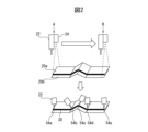
- FIG. 2 is a diagram schematically showing welding work by a robot.
- FIG. 7 is a diagram illustrating an example of teaching a search starting point using a user interface.
- FIG. 7 is a diagram illustrating an example of teaching a search end point using a user interface.
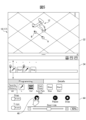
- FIG. 3 is a diagram illustrating an example of executing a search program using a user interface.
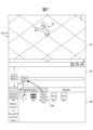
- FIG. 3 is a diagram illustrating an example of automatically generating a work program using a user interface.
- FIG. 7 is a diagram showing another example of teaching a search point using a user interface.
- 8 is a diagram showing an example of a wizard displayed on the user interface in the example of FIG. 7.
- FIG. 3 is a flowchart illustrating an example of processing in the program generation device.
- FIG. 1 is a schematic configuration diagram of a robot system according to a preferred embodiment.
- the robot system 10 includes at least one robot 12, a robot control device 14 that controls the robot 12, and a teaching pendant 16 that is communicably connected to the robot control device 14 by wireless or wire.
- the robot 12 is, for example, an industrial articulated robot, and is configured to have a movable part (robot arm) 18 and a movable part 18 attached to the tip thereof so as to be able to perform a predetermined work on a workpiece (work) 20.
- the sensor 24 includes a work tool 22 that has been moved, and a sensor 24 that can detect the position of a work site (for example, a work line) on the workpiece 20 by the work tool 22.
- the work tool 22 is a welding torch
- the robot system 10 includes a welding power source 26 that supplies current to the welding torch 22 based on a command from the robot controller 14.
- the work line includes the welding part of the workpiece, but the present disclosure is not limited to this.
- the work line includes the sealing part of the workpiece.
- the working tool 22 can also be a nozzle or the like for discharging adhesive.
- the senor 24 includes an emitting section that emits light (e.g., laser light) based on a command from the robot control device 14, and an image sensor (CCD, CMOS) that receives light reflected by the workpiece and converts it photoelectrically.
- It is a laser scanner type three-dimensional sensor (laser sensor) having a three-dimensional sensor (laser sensor), which is attached to the tip of the movable part 18 or the welding torch 22 using an appropriate fixture (not shown), and moves the workpiece along the work line. The work line can be searched by scanning continuously.
- the sensor is not limited to a laser sensor, and any sensor capable of detecting a work line can be used.
- a three-dimensional sensor can also be used. Examples of 3D sensors include TOF (Time of Flight) cameras that capture distance images using the optical time-of-flight method, or stereo cameras that detect 3D positions using parallax captured by two 2D cameras. Available for use.
- TOF Time of Flight
- the robot 12 is configured to be able to perform various processing and operations such as welding based on commands sent from the robot control device 14.
- the robot control device 14 includes a processor and a storage unit (memory, etc.), and can control the robot 12 based on a work program to be described later.
- the robot control device 14 can generate and save a search program, which will be described later, and execute it to control the sensor 24. That is, in this embodiment, the processor of the robot control device 14 has the functions of a display control section and a program generation section.
- a computer such as a personal computer (PC) 28 connected to the control device 14 by wire or wirelessly and having a processor and a storage unit (memory, etc.) generates each program, The generated program may be sent from the PC 28 to the control device 14.
- PC personal computer
- storage unit memory, etc.
- the teaching pendant 16 includes a reception section such as a keyboard or touch panel that can receive various inputs from the user, and a display section such as a display, and the reception section and the display section constitute a user interface to be described later.
- a reception section such as a keyboard or touch panel that can receive various inputs from the user
- a display section such as a display
- the reception section and the display section constitute a user interface to be described later.
- FIG. 2 is a diagram schematically illustrating welding as an example of work performed by the robot 12.
- the shapes of two plate-shaped workpieces 20a and 20b having ups and downs are measured using a laser sensor 24 attached to a welding torch 22, and teaching points are automatically generated based on the information obtained from the sensor 24. Then, arc welding is performed along the welding line 30.
- the user or operator of the robot 12 executes a search program and a work program, which will be described later, via a user interface (UI) 17 displayed on the display of the teaching pendant 16, etc.
- UI user interface
- the UI 17 has the functions of a display section that allows the user to visually recognize various information, and a reception section that receives various inputs from the user.
- the UI 17 includes a robot display area 32 that can display a robot image corresponding to the position and orientation of the actual robot 12, a timeline display area 34 that can display icons (described later) arranged in chronological order, and a timeline display area 34 that allows the user to select desired icons.
- the menu display area 36 includes a menu display area 36 in which each icon can be displayed for selection.
- step S1 the user of the robot 12 instructs the robot 12 about the search start position (search start point). Specifically, the user moves the robot 12 so that it is located at a search starting point A (see FIG. 2) where the sensor 24 can detect the welding start position or its vicinity.
- a search starting point A see FIG. 2
- the robot display area 32 an image corresponding to the position and posture of the actual robot 12 moved by the user can be displayed.
- the user selects the icon 38 (L) representing the search point from the menu display area 36 and moves it to the timeline display area 34 by drag and drop or other operations. move it to Then, an icon "L" is placed at the left end of the timeline display area 34, which means that the search start position has been taught.
- the search start position is different from the welding start position (work start position).
- the search start position and the welding start position may end up being the same position.
- the search end position is different from the welding end position (work end position), but may end up being the same position.
- the user selects an icon 40 (Start) representing a search start command from the menu display area 36 and moves it to the timeline display area 34 by an operation such as drag and drop. Then, the icon “Start” is placed to the right of the icon “L” in the timeline display area 34.
- the search start command allows the user to set various parameters in the search program (step S2).
- the search program may include at least one of information regarding the search range of the sensor 24, information regarding the output of the sensor 24, information regarding the route of the sensor 24, and information regarding the automatically generated work program.
- the user can input the interval between each teaching point as information regarding the path of the sensor 24.
- the user can also input information regarding the automatically generated work program, such as specifying the torch angle and welding speed in the work program.
- the user of the robot 12 instructs the robot 12 about the search end position (search end point) (step S3). Specifically, the user moves the robot 12 so that the sensor 24 is located at a search starting point B (see FIG. 2) where the sensor 24 can detect the welding end position or its vicinity.
- the robot display area 32 displays the state of the actual robot 12 moved by the user.
- the user selects the icon 38 (L) representing the teaching point from the menu display area 36 and moves it to the timeline display area 34 by drag and drop or other operations. move it to Then, an icon "L” is placed to the right of the icon “Start” in the timeline display area 34, and this means that the search end position has been taught.
- an icon 42 representing the end of the search from the menu display area 36 and moves it to the timeline display area 34 by drag and drop or other operations. Then, an icon “Stop” is placed at the right end of the timeline display area 34.
- the search program can be displayed as a series of icons arranged and displayed in chronological order within the timeline display area 34.
- the user can create a search program through visually and intuitively easy-to-understand operations via the teaching operation panel (UI). Therefore, even if the user is not an expert, he or she can create the desired search program. can be created in a short time with simple operations.
- the user taught the search start point and the search end point by directly moving the robot with his or her hand (so-called direct teaching); however, the present disclosure is not limited to this, and the user may move the robot by jogging, for example. You can also do it.
- the user can add any point in addition to the search start point and search end point.
- at least one intermediate point can be taught between the search start point and the search end point, and furthermore, the operation mode of the torch can also be set in a straight line.
- the movement is not limited to this, and the movement can also be performed along an arc, for example. Information regarding these intermediate points can also be displayed as icons.
- step S5 the search program generated in step S4 is executed (step S5).
- the scanning laser is irradiated from the sensor 24 toward the work in the section from the search start position to the search end position, and at least one teaching point is generated in the same section.
- a work program including teaching points is automatically generated (step S6).
- a program execution menu 44 is displayed, and when the user touches the program execution button 46 of the execution menu 44, the robot 12 starts a search operation based on the search program. .
- teaching point of the robot 12 is determined based on this result. Generate automatically.
- teaching points 54b to 54d are generated. More specifically, teaching points 54b and 54d correspond to the bottom of the raised part, and teaching point 54c corresponds to the top of the raised part.
- a work program including the generated teaching points is automatically generated.
- the work program is displayed in the timeline display area 34 as a combination of icons 48.
- the work program 48 includes an icon 54a representing the start of welding, an icon 54e representing the end of welding, and icons 54b to 54d representing each teaching point in the welding work between these, and these icons are arranged on a timeline. They are displayed in chronological order within the display area 34.
- icons 54a representing the start of welding
- icons 54e representing the end of welding
- icons 54b to 54d representing each teaching point in the welding work between these
- buttons 54a to 54e are displayed, but the icon 54a containing information about the search start position, the icon 54e containing information about the search end position, and the icon 54e containing information about the search start position, and the icon 54e between the search start position and the search end position are displayed. At least one of the icons 54b-54d may be displayed, including information regarding the midpoint of the image.
- the user can check and edit the automatically generated work program via the UI 17 of the teaching pendant 16. For example, by clicking on any of the icons 54a to 54e in the timeline display area 34, various icons containing work information etc. are displayed in the menu display area 36, and the user can perform work such as correcting the position of the teaching point. You will be able to set and change various parameters within the program.
- the robot is controlled based on the work program (step S7). This allows the robot to perform predetermined work such as welding based on the automatically generated work program.
- FIGS. 7-8 show other examples of UIs for generating search programs.
- the second embodiment only the parts that are different from the first embodiment will be explained, and the explanation of the parts that may be the same as the first embodiment will be omitted.
- FIG. 7 shows an example of the UI displayed on the teaching pendant 16.
- the user selects the route teaching icon 60 (Auto Path Scan) displayed in the menu display area 36 and moves it to the timeline display area 34 by drag and drop or other operations.
- an icon "Auto Path Scan” is placed at the left end of the timeline display area 34, and a wizard for setting a search route as illustrated in FIG. 8 is displayed at an appropriate location on the UI 17 of the teaching pendant 16.
- search route setting wizard first, as shown by reference numeral 62, a screen prompting the user to memorize the search starting point is displayed. In response to this, the user moves the robot 12 to the search start point A and taps the memory start button 64, as in the first embodiment. As a result, information on the search starting point A is stored in the memory of the control device 14 or the like.
- a screen prompting the user to memorize the search end point is displayed.
- the user moves the robot 12 to the search starting point B and taps the memory start button 68, as in the first embodiment.
- information on the search end point B is stored in the memory of the control device 14, and a search program substantially similar to that shown in FIG. 4 is generated. Note that at this stage, the user can set various parameters in the search program.
- a screen prompting the search route to be detected is displayed.
- the detection start button 72 in response to this, the search route from the search start point A to the search end point B is detected using the generated search program, and the teaching point is also automatically set at this stage. is generated.
- a screen notifying the user to that effect is displayed as indicated by reference numeral 74.
- a robot work program including automatically generated teaching points has also been automatically generated. The user can check and edit the automatically generated work program from a screen similar to that shown in FIG. 6.
- the UI 17 for generating the search program and the accompanying user operations are different from the first embodiment, but the obtained search program itself can be substantially the same as in the first embodiment, and therefore The work program obtained by executing the search program can also be substantially the same as in the first embodiment.
- the user's teaching work in creating a search program for generating teaching points is greatly simplified by visual operation/input via the UI. Therefore, even an inexperienced user can create a desired search program in a short time with simple operations, and furthermore, by executing the search program, appropriate teaching points (work programs) can be automatically generated.
Landscapes
- Engineering & Computer Science (AREA)
- Physics & Mathematics (AREA)
- Robotics (AREA)
- Mechanical Engineering (AREA)
- General Physics & Mathematics (AREA)
- Automation & Control Theory (AREA)
- Geometry (AREA)
- Human Computer Interaction (AREA)
- Manufacturing & Machinery (AREA)
- Numerical Control (AREA)
- Manipulator (AREA)
Priority Applications (6)
| Application Number | Priority Date | Filing Date | Title |
|---|---|---|---|
| CN202280084110.3A CN118414587A (zh) | 2022-03-07 | 2022-03-07 | 机器人的搜索程序的生成装置 |
| JP2024505681A JPWO2023170764A1 (https=) | 2022-03-07 | 2022-03-07 | |
| US18/840,146 US20250187185A1 (en) | 2022-03-07 | 2022-03-07 | Device for generating search program for robot |
| DE112022005804.8T DE112022005804T5 (de) | 2022-03-07 | 2022-03-07 | Vorrichtung zum erzeugen eines suchprogramms für einen roboter |
| PCT/JP2022/009814 WO2023170764A1 (ja) | 2022-03-07 | 2022-03-07 | ロボットの探索プログラムの生成装置 |
| TW112104191A TW202348370A (zh) | 2022-03-07 | 2023-02-07 | 機器人之探索程式之產生裝置 |
Applications Claiming Priority (1)
| Application Number | Priority Date | Filing Date | Title |
|---|---|---|---|
| PCT/JP2022/009814 WO2023170764A1 (ja) | 2022-03-07 | 2022-03-07 | ロボットの探索プログラムの生成装置 |
Publications (1)
| Publication Number | Publication Date |
|---|---|
| WO2023170764A1 true WO2023170764A1 (ja) | 2023-09-14 |
Family
ID=87936245
Family Applications (1)
| Application Number | Title | Priority Date | Filing Date |
|---|---|---|---|
| PCT/JP2022/009814 Ceased WO2023170764A1 (ja) | 2022-03-07 | 2022-03-07 | ロボットの探索プログラムの生成装置 |
Country Status (6)
| Country | Link |
|---|---|
| US (1) | US20250187185A1 (https=) |
| JP (1) | JPWO2023170764A1 (https=) |
| CN (1) | CN118414587A (https=) |
| DE (1) | DE112022005804T5 (https=) |
| TW (1) | TW202348370A (https=) |
| WO (1) | WO2023170764A1 (https=) |
Citations (6)
| Publication number | Priority date | Publication date | Assignee | Title |
|---|---|---|---|---|
| JPH07308879A (ja) * | 1994-05-13 | 1995-11-28 | Nippon Telegr & Teleph Corp <Ntt> | ロボットの自動教示法 |
| JPH08103870A (ja) * | 1994-10-04 | 1996-04-23 | Sekisui Chem Co Ltd | 溶接ロボット |
| JPH09183087A (ja) * | 1995-12-28 | 1997-07-15 | Komatsu Ltd | 作業ロボット装置 |
| JPH11883A (ja) * | 1997-06-13 | 1999-01-06 | Yaskawa Electric Corp | ロボット動作の自動教示方法、ロボットの軌跡修正方法および溶接ロボットの制御方法 |
| JP2012135858A (ja) * | 2010-12-28 | 2012-07-19 | Toyota Motor Corp | 操作環境モデル構築システム、および操作環境モデル構築方法 |
| JP2016064469A (ja) * | 2014-09-25 | 2016-04-28 | 株式会社ダイヘン | 可搬式操作装置及び作業機械制御システム |
Family Cites Families (6)
| Publication number | Priority date | Publication date | Assignee | Title |
|---|---|---|---|---|
| JPS63114853A (ja) * | 1986-10-31 | 1988-05-19 | Kobe Steel Ltd | センサ付自動加工装置 |
| JPH07104831A (ja) * | 1993-10-08 | 1995-04-21 | Fanuc Ltd | レーザセンサを用いたロボットの自動位置教示方法 |
| JP2001129776A (ja) | 1999-11-05 | 2001-05-15 | Fanuc Ltd | センサを使った検出線に対する追従装置 |
| JP4347386B2 (ja) * | 2008-01-23 | 2009-10-21 | ファナック株式会社 | 加工用ロボットプラグラムの作成装置 |
| JP7238362B2 (ja) * | 2018-11-27 | 2023-03-14 | 株式会社タダノ | 溶接ロボット |
| EP4446046A4 (en) * | 2021-12-08 | 2025-06-11 | Panasonic Intellectual Property Management Co., Ltd. | OFFLINE TEACHING DEVICE AND OFFLINE TEACHING METHOD |
-
2022
- 2022-03-07 DE DE112022005804.8T patent/DE112022005804T5/de active Pending
- 2022-03-07 US US18/840,146 patent/US20250187185A1/en active Pending
- 2022-03-07 JP JP2024505681A patent/JPWO2023170764A1/ja active Pending
- 2022-03-07 WO PCT/JP2022/009814 patent/WO2023170764A1/ja not_active Ceased
- 2022-03-07 CN CN202280084110.3A patent/CN118414587A/zh active Pending
-
2023
- 2023-02-07 TW TW112104191A patent/TW202348370A/zh unknown
Patent Citations (6)
| Publication number | Priority date | Publication date | Assignee | Title |
|---|---|---|---|---|
| JPH07308879A (ja) * | 1994-05-13 | 1995-11-28 | Nippon Telegr & Teleph Corp <Ntt> | ロボットの自動教示法 |
| JPH08103870A (ja) * | 1994-10-04 | 1996-04-23 | Sekisui Chem Co Ltd | 溶接ロボット |
| JPH09183087A (ja) * | 1995-12-28 | 1997-07-15 | Komatsu Ltd | 作業ロボット装置 |
| JPH11883A (ja) * | 1997-06-13 | 1999-01-06 | Yaskawa Electric Corp | ロボット動作の自動教示方法、ロボットの軌跡修正方法および溶接ロボットの制御方法 |
| JP2012135858A (ja) * | 2010-12-28 | 2012-07-19 | Toyota Motor Corp | 操作環境モデル構築システム、および操作環境モデル構築方法 |
| JP2016064469A (ja) * | 2014-09-25 | 2016-04-28 | 株式会社ダイヘン | 可搬式操作装置及び作業機械制御システム |
Also Published As
| Publication number | Publication date |
|---|---|
| CN118414587A (zh) | 2024-07-30 |
| US20250187185A1 (en) | 2025-06-12 |
| TW202348370A (zh) | 2023-12-16 |
| DE112022005804T5 (de) | 2024-10-10 |
| JPWO2023170764A1 (https=) | 2023-09-14 |
Similar Documents
| Publication | Publication Date | Title |
|---|---|---|
| JP5526881B2 (ja) | ロボットシステム | |
| EP2375298A2 (en) | Programming method for a robot, programming apparatus for a robot, and robot control system | |
| CN109834695B (zh) | 进行机器人的示教操作的示教装置以及示教方法 | |
| JP4167940B2 (ja) | ロボットシステム | |
| EP2081096B1 (en) | Controller of work piece-conveying robot | |
| JP3950805B2 (ja) | 教示位置修正装置 | |
| US10656618B2 (en) | Numerical controller | |
| JP2006289531A (ja) | ロボット位置教示のための移動制御装置、ロボットの位置教示装置、ロボット位置教示のための移動制御方法、ロボットの位置教示方法及びロボット位置教示のための移動制御プログラム | |
| US20170087717A1 (en) | Offline teaching device | |
| JP7414851B2 (ja) | ロボットの制御装置、ロボットシステム、制御方法、及びコンピュータプログラム | |
| JP2005108144A (ja) | ロボットの補正データ確認装置 | |
| JP5805457B2 (ja) | 溶接ロボット制御装置 | |
| US12583104B2 (en) | System and method for teaching a robot program | |
| JP2011253300A (ja) | ロボット制御システム | |
| JP2014065100A (ja) | ロボットシステム、及びロボットのティーチング方法 | |
| JP2008221281A (ja) | 自動溶接機の位置検出システム | |
| CN111077805A (zh) | 测量程序选择辅助设备和测量控制设备 | |
| WO2022181643A1 (ja) | レーザ加工装置の動作を教示するための教示装置、及び教示方法 | |
| WO2023170764A1 (ja) | ロボットの探索プログラムの生成装置 | |
| JP5670147B2 (ja) | アーク溶接ロボット制御装置 | |
| JP2010149225A (ja) | ロボットシステム、ロボットシステムの制御装置および制御方法 | |
| WO2024009484A1 (ja) | 制御装置及び制御方法 | |
| JP5636148B2 (ja) | 自動溶接機の位置検出システム | |
| JP7195476B1 (ja) | 作業プログラム作成システム及び作業プログラム作成方法 | |
| JP6405168B2 (ja) | 倣い制御装置、溶接ロボットシステムおよび倣い制御方法 |
Legal Events
| Date | Code | Title | Description |
|---|---|---|---|
| 121 | Ep: the epo has been informed by wipo that ep was designated in this application |
Ref document number: 22930750 Country of ref document: EP Kind code of ref document: A1 |
|
| ENP | Entry into the national phase |
Ref document number: 2024505681 Country of ref document: JP Kind code of ref document: A |
|
| WWE | Wipo information: entry into national phase |
Ref document number: 202280084110.3 Country of ref document: CN |
|
| WWE | Wipo information: entry into national phase |
Ref document number: 112022005804 Country of ref document: DE |
|
| WWE | Wipo information: entry into national phase |
Ref document number: 18840146 Country of ref document: US |
|
| 122 | Ep: pct application non-entry in european phase |
Ref document number: 22930750 Country of ref document: EP Kind code of ref document: A1 |
|
| WWP | Wipo information: published in national office |
Ref document number: 18840146 Country of ref document: US |