WO2023166653A1 - 真空処理装置 - Google Patents
真空処理装置 Download PDFInfo
- Publication number
- WO2023166653A1 WO2023166653A1 PCT/JP2022/009105 JP2022009105W WO2023166653A1 WO 2023166653 A1 WO2023166653 A1 WO 2023166653A1 JP 2022009105 W JP2022009105 W JP 2022009105W WO 2023166653 A1 WO2023166653 A1 WO 2023166653A1
- Authority
- WO
- WIPO (PCT)
- Prior art keywords
- sealing member
- vacuum processing
- processing apparatus
- opening
- hinge mechanism
- Prior art date
- Legal status (The legal status is an assumption and is not a legal conclusion. Google has not performed a legal analysis and makes no representation as to the accuracy of the status listed.)
- Ceased
Links
Images


Classifications
-
- B—PERFORMING OPERATIONS; TRANSPORTING
- B01—PHYSICAL OR CHEMICAL PROCESSES OR APPARATUS IN GENERAL
- B01J—CHEMICAL OR PHYSICAL PROCESSES, e.g. CATALYSIS OR COLLOID CHEMISTRY; THEIR RELEVANT APPARATUS
- B01J3/00—Processes of utilising sub-atmospheric or super-atmospheric pressure to effect chemical or physical change of matter; Apparatus therefor
- B01J3/03—Pressure vessels, or vacuum vessels, having closure members or seals specially adapted therefor
-
- C—CHEMISTRY; METALLURGY
- C23—COATING METALLIC MATERIAL; COATING MATERIAL WITH METALLIC MATERIAL; CHEMICAL SURFACE TREATMENT; DIFFUSION TREATMENT OF METALLIC MATERIAL; COATING BY VACUUM EVAPORATION, BY SPUTTERING, BY ION IMPLANTATION OR BY CHEMICAL VAPOUR DEPOSITION, IN GENERAL; INHIBITING CORROSION OF METALLIC MATERIAL OR INCRUSTATION IN GENERAL
- C23C—COATING METALLIC MATERIAL; COATING MATERIAL WITH METALLIC MATERIAL; SURFACE TREATMENT OF METALLIC MATERIAL BY DIFFUSION INTO THE SURFACE, BY CHEMICAL CONVERSION OR SUBSTITUTION; COATING BY VACUUM EVAPORATION, BY SPUTTERING, BY ION IMPLANTATION OR BY CHEMICAL VAPOUR DEPOSITION, IN GENERAL
- C23C16/00—Chemical coating by decomposition of gaseous compounds, without leaving reaction products of surface material in the coating, i.e. chemical vapour deposition [CVD] processes
- C23C16/44—Chemical coating by decomposition of gaseous compounds, without leaving reaction products of surface material in the coating, i.e. chemical vapour deposition [CVD] processes characterised by the method of coating
-
- F—MECHANICAL ENGINEERING; LIGHTING; HEATING; WEAPONS; BLASTING
- F16—ENGINEERING ELEMENTS AND UNITS; GENERAL MEASURES FOR PRODUCING AND MAINTAINING EFFECTIVE FUNCTIONING OF MACHINES OR INSTALLATIONS; THERMAL INSULATION IN GENERAL
- F16J—PISTONS; CYLINDERS; SEALINGS
- F16J13/00—Covers or similar closure members for pressure vessels in general
- F16J13/02—Detachable closure members; Means for tightening closures
- F16J13/04—Detachable closure members; Means for tightening closures attached with a bridge member
Definitions
- the present invention relates to a vacuum processing apparatus.
- Patent Document 1 discloses a vacuum processing apparatus that does not require adjustment during assembly and can be assembled with high accuracy.
- the vacuum processing apparatus has a hinge mechanism for opening and closing the top cover, and the top cover can be displaced up and down by means of an elongated hinge hole, a hinge shaft, and a spring mechanism provided in the hinge mechanism.
- a chamber having an upper wall in which a first opening and a second opening are formed, an upper lid that opens and closes the first opening, and a chamber provided to cover the second opening a hinge mechanism for rotatably supporting the upper cover with respect to the first opening; and an elastically deformable first hinge mechanism provided between the upper cover and the upper wall so as to surround the first opening.
- a vacuum processing apparatus comprising: a sealing member; and an elastically deformable second sealing member provided between the hinge mechanism and the upper wall so as to surround the second opening. be done.
- a vacuum processing apparatus that can reliably seal between the upper lid and the chamber in atmospheric pressure and vacuum conditions.
- FIG. 1 is a schematic cross-sectional view showing a vacuum processing apparatus according to one embodiment of the present invention
- FIG. 1 is a schematic cross-sectional view showing a vacuum processing apparatus according to one embodiment of the present invention
- FIG. 4 is a top view showing the positional relationship among the chamber, first sealing member, and second sealing member of the vacuum processing apparatus according to one embodiment of the present invention
- FIG. FIG. 4 is an enlarged cross-sectional view showing a state before the first sealing member is elastically deformed in the vacuum processing apparatus according to the embodiment of the present invention
- FIG. 4 is an enlarged cross-sectional view showing a state after the first sealing member is elastically deformed in the vacuum processing apparatus according to the embodiment of the present invention
- FIG. 5 is an enlarged cross-sectional view showing a state before the second sealing member is elastically deformed in the vacuum processing apparatus according to the embodiment of the present invention
- FIG. 5 is an enlarged cross-sectional view showing a state after the second sealing member is elastically deformed in the vacuum processing apparatus according to the embodiment of the present invention
- FIG. 4 is a diagram showing the relationship between the force applied per unit length and the compression margin on the center circumference of a rubber O-ring having a predetermined hardness.
- FIG. 5 is an enlarged cross-sectional view for explaining an adjustment mechanism of a vacuum processing apparatus according to a comparative example
- FIG. 5 is an enlarged cross-sectional view for explaining an adjustment mechanism of a vacuum processing apparatus according to a comparative example;
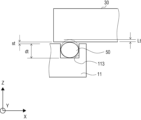
- FIG. 1 and 2 are schematic cross-sectional views showing a vacuum processing apparatus 1 according to one embodiment of the present invention.
- 1 shows a state in which an upper lid 30, which will be described later, is closed
- FIG. 2 shows a state in which the upper lid 30 is open.
- the vacuum processing apparatus 1 includes a chamber 10, an exhaust mechanism 20, an upper lid 30, a hinge mechanism 40, a first sealing member 50, and a second sealing member 60. Prepare.
- the chamber 10 includes a top wall portion 11 , a side wall portion 12 , a side wall portion 13 and a bottom wall portion 14 .
- the chamber 10 has an internal space S surrounded by a top wall portion 11 , a side wall portion 12 , a side wall portion 13 and a bottom wall portion 14 .
- the upper wall portion 11 is formed with a first opening portion 111 and a second opening portion 112 .
- the first opening 111 is an end of an opening that is used when carrying an object into the internal space S and when carrying an object out of the internal space S.
- the second opening 112 is a through hole that forms a ventilation path that communicates with the internal space S.
- the gas existing in the portion surrounded by the second sealing member 60 through the second opening 112 and a through hole 421, which will be described later, is also evacuated at the same time. be done.
- the second opening 112 is smaller than the first opening 111 .
- a groove 113 is formed in the upper wall portion 11 so as to surround the first opening portion 111 on the upper surface side.
- the groove 113 accommodates the first sealing member 50 .
- the size of the groove 113 is designed to correspond to the size of the first sealing member 50 .
- a groove 114 is formed in the upper wall portion 11 so as to surround the second opening portion 112 on the upper surface side.
- the groove 114 accommodates a second sealing member 60d, which will be described later.
- the size of the groove 114 is designed to correspond to the size of the second sealing member 60d.
- An exhaust port 141 is formed in the bottom wall portion 14 .
- the exhaust port 141 is connected to the exhaust mechanism 20 .
- the exhaust mechanism 20 has an exhaust line 21 , a valve 22 and a pump 23 .
- the exhaust mechanism 20 forms a gas flow toward the exhaust port 141 and the exhaust line 21 according to instructions from a control device (not shown) or by manually controlling the opening and closing of the valve 22 and the driving of the pump 23, S can be evacuated.
- the upper lid 30 is a lid member that is provided outside the chamber 10 and covers the first opening 111 .
- a portion of the upper lid 30 is connected to the hinge mechanism 40 .
- the vertical and horizontal dimensions of the upper lid 30 are larger than the vertical and horizontal dimensions of the first opening 111 .
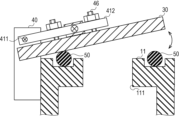
- the hinge mechanism 40 has a hinge body 41, four pedestals 42, for example, and shoulder bolts 43 for fixing the pedestals 42 and the chamber 10, and enables the upper lid 30 to open and close with respect to the first opening 111.
- the hinge body 41 has a hinge shaft 411 and an arm portion 412 rotatable about the hinge shaft 411 .
- the pedestal 42 is a member that supports the hinge body 41 from the bottom side. As shown in FIG. 1, in the present embodiment, four pedestals 42 are provided and superimposed in the vertical direction (the Z-axis direction in the figure). Note that the number of pedestals 42 is not limited to four, and an optimum number can be obtained by calculation described later.
- Through-holes 421 are formed in the central portions of the second to fourth pedestals 42b to 42d from the top.
- the through-hole 421 communicates with the second opening 112 of the upper wall 11 in the vertical direction (the Z-axis direction in the figure). That is, the through-hole 421 is surrounded by the second sealing member 60 and constitutes a ventilation path that communicates with the internal space S via the second opening 112 .
- grooves 422 are formed on the upper surfaces of the pedestals 42b to 42d so as to surround the through holes 421, respectively.
- the three grooves 422 respectively accommodate the second sealing members 60a-60c.
- the size of the groove 422 is designed to correspond to the size of the second sealing members 60a-60c.
- the material, hardness and size of the four second sealing members 60a to 60d are the same.
- the three grooves 422 and the above-described groove 114 are arranged along the vertical direction.
- the shoulder bolt 43 is a member for fixing the hinge mechanism 40 (hinge body 41 and pedestals 42b to 42d) to the chamber 10 in the vertical direction.
- the hinge mechanism 40 is fixed by the seating surface of the shoulder bolt 43 .
- the length of the threaded portion of the shoulder bolt 43 is designed so that the second sealing member 60 is properly crushed when it is tightened into the chamber 10 .
- the first sealing member 50 is a sealing member that elastically deforms according to the force applied from the upper lid 30 .
- the force applied from the upper lid 30 to the first sealing member 50 includes a vertically downward pressing force due to the weight of the upper lid 30 and a force due to the differential pressure between the atmospheric pressure and the vacuum during the evacuation process.
- the first sealing member 50 is provided so as to surround the first opening 111 in the horizontal direction (the XY direction in the drawing). Also, the first sealing member 50 is accommodated in a groove 113 formed in the upper wall portion 11 so as to match the position of the upper lid 30 . The first sealing member 50 is elastically deformed while being sandwiched between the upper wall portion 11 of the chamber 10 and the upper lid 30 when the upper lid 30 closes the first opening 111 . The elastic deformation of the first sealing member 50 seals the internal space S of the chamber 10 on the first opening 111 side.
- the second sealing member 60 is a sealing member that elastically deforms according to the force applied from the hinge mechanism 40 in the vertical direction.
- the force applied from the hinge mechanism 40 to the second sealing member 60 includes the vertically downward pressing force due to the weight of the hinge mechanism 40 and the vertically downward pressure due to the differential pressure between the atmospheric pressure and the vacuum during the evacuation process. There is power to arise.
- the second sealing member 60 is composed of four second sealing members 60a to 60d arranged in the vertical direction.
- the second sealing members 60a to 60c are provided so as to surround the through hole 421 in the horizontal direction.
- the second sealing member 60d is provided so as to surround the second opening 112 in the horizontal direction.
- the second sealing members 60a-60c are housed in grooves 422 formed in the pedestals 42b-42d, respectively.
- the second sealing member 60d is accommodated in a groove 114 formed in the upper wall portion 11 so as to match the position of the hinge mechanism 40 in the horizontal direction.
- the plurality of second sealing members 60a to 60d are elastically deformed, respectively, so that the gap between the pedestal 42a and the pedestal 42b, the gap between the pedestal 42b and the pedestal 42c, the gap between the pedestal 42c and the pedestal 42d, the pedestal 42d and the upper wall The gaps with the portions 11 are sealed respectively.
- first sealing member 50 is arranged on the upper lid 30 side, and four second sealing members 60a to 60d are arranged on the hinge mechanism 40 side. Therefore, when the evacuation process is performed, the displacement amount obtained by subtracting the length after being crushed (after evacuation) from the length in the vertical direction before the first sealing member 50 is crushed (before evacuation)
- First crushing amount is the sum of displacement amounts (second crushing amount) obtained by subtracting the length after crushing from the length in the vertical direction before crushing of each of the plurality of second sealing members 60 to 60d. shall be adjusted to match the In this specification, the term “matches" is used not only when two numerical values are exactly the same, but also when two numerical values are equivalent. A specific range of "equivalent” will be described later.
- the phrase “amount of crushing” means the amount of compression of the first sealing member 50 and the second sealing member 60 that are crushed in the vertical direction.
- compression margin means the ratio of the amount of compression (the amount of compression) to the original thickness of the first sealing member 50 and the second sealing member 60 that are compressed in the vertical direction, that is, the compression ratio.
- O-rings with a Viton hardness (Shore A) of 70 used in a general vacuum processing apparatus are used.
- FIG. 3 is a top view showing the positional relationship among the chamber 10, the first sealing member 50 and the second sealing member 60.
- FIG. Here, for convenience of explanation, a state in which the upper lid 30 and the hinge mechanism 40 are not attached to the chamber 10 is shown.
- the dashed lines in the drawing indicate the positions where the upper lid 30 and the hinge mechanism 40 are attached.
- Fot [N/mm] Ft [N]/Ct [mm]
- Foh [N/mm] Fh [N]/Ch [mm]
- FIG. 4 the relationship between the magnitude of the force applied to the first sealing member 50 and the second sealing member 60 and the amount of crushing during the evacuation process will be described with reference to FIGS. 4 to 7.
- FIG. 4 the relationship between the magnitude of the force applied to the first sealing member 50 and the second sealing member 60 and the amount of crushing during the evacuation process
- FIG. 4 is an enlarged cross-sectional view showing a state before the first sealing member 50 elastically deforms in the vacuum processing apparatus 1 according to one embodiment of the present invention.
- FIG. 5 is an enlarged sectional view showing a state after the first sealing member 50 is elastically deformed.
- Wt represents the diameter (wire diameter) of the first sealing member 50 in a vertical cross-sectional view.
- dt represents the depth of the groove 113 of the upper wall portion 11 that accommodates the first sealing member 50 .
- st represents the length of the gap between the bottom surface of the top lid 30 and the top surface of the top wall portion 11 after the first sealing member 50 is crushed on the top lid 30 side.
- the crushing amount Lt of the first sealing member 50 in the vertical direction is calculated as follows.
- Lt [mm] Wt [mm] - dt [mm] - st [mm]
- the compression margin Qt [%] of the first sealing member 50 is calculated as follows.
- Qt [%] (Lt/Wt) x 100
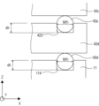
- FIG. 6 is an enlarged cross-sectional view showing a state before the second sealing member 60 is elastically deformed in the vacuum processing apparatus 1 according to one embodiment of the present invention.
- FIG. 7 is an enlarged sectional view showing the state after the second sealing member 60 is elastically deformed. 6 and 7 show the groove 422 accommodating the second sealing member 60c and the groove 114 accommodating the second sealing member 60d.
- Wh represents the diameter (wire diameter) of the second sealing member 60 in a vertical cross-sectional view.
- dh represents the depth of the groove 422 of the base 60 that accommodates the second sealing member 60 and the depth of the groove 114 of the upper wall portion 11, respectively.
- sh is the length of the gap between the pedestal 42c and the pedestal 42d adjacent to each other in the vertical direction and the distance between the bottom surface of the pedestal 42d and the top surface of the upper wall portion 11 after the second sealing member 60 is compressed on the hinge mechanism 40 side; Each represents the length of the gap.
- the crushing amount Lh of the second sealing member 60 in the vertical direction is calculated as follows.
- Lh [mm] Wh [mm] - dh [mm] - sh [mm]
- the crushing margin Qt of the first sealing member 50 and the crushing margin Qh of the second sealing member 60 are both designed to be about 10% to 30%. is recommended as an appropriate value.
- the diameter Wh of the second sealing member 60, the depth dh of the grooves 114 and 422, and the amount of vertical displacement due to the crushing of the first sealing member 50 (second crushing amount) be Lh.
- Wh, Lh and dh satisfy the formula Wh ⁇ Lh>dh. That is, in the present embodiment, after the evacuation process, a part of the first sealing member 50 and a part of the second sealing member 60 are always pushed into the grooves of the storage destinations to seal the grooves.
- the filling rate of the members increases, and the first sealing member 50 collapses by Lt, and the second sealing member 60 collapses by Lh per used quantity. This is due to the structure in which the through hole 421 shown in FIG. 1 communicates with the second opening 112 of the castle wall 11 in the vertical direction (the Z-axis direction in the drawing).
- Fig. 8 is a diagram showing the relationship between the force applied per unit length and the compression ratio on the central circumference of a rubber O-ring having a predetermined hardness.
- the horizontal axis indicates the force x applied per unit length
- the vertical axis indicates the compression margin y.
- FIG. 8 is a double logarithmic graph
- the force x and the compression margin y on the straight line in the figure have the relationship shown in the following equation (1).
- Logy a(Logx)+Logc Formula (1)
- the values of constants a and c differ depending on the diameter W of the O-ring.
- the unit length of the first sealing member 50 is reduced during the evacuation process.
- the magnitude relationship between the force Fot applied to the contact and the force Foh applied to the second sealing member 60 per unit length is Fot>Foh.
- the crushing amount of the first sealing member 50 at the time of Fot and the crushing amount of the second sealing member 60 at the time of Foh must be equal to each other. There is a need to.
- the wire diameter of the O-ring used as the second sealing member 60 is made thinner than the wire diameter of the O-ring used as the first sealing member 50, and these are stacked in multiple stages. match.
- the value of N is determined so that the relationship of Lt ⁇ N ⁇ Lh is established even when Ft>Fh.
- an O-ring having a diameter Wt of 6.98 [mm] is used as the first sealing member 50 on the upper lid 30 side
- an O-ring having a diameter Wh of 2.62 [mm] is used as the second sealing member 60 on the hinge mechanism 40 side.
- N is an integer of 2 or more
- the number of used second sealing members 60 is The calculation method to be obtained. It is assumed that the relationship between the force x applied per unit length and the compression margin y can be obtained from known data as shown in FIG.
- ceil(x) in the formula is a ceiling function that obtains the smallest integer of N or more with respect to the real number x. The reason why it is necessary to use the ceiling function is that N must be an integer in order to represent the number of second sealing members 60 .
- a displacement amount obtained by subtracting the length after being crushed by the differential pressure between the vacuum and the atmosphere is the displacement amount obtained by subtracting the length after compression from the diameter Wh of the second sealing member 60 before compression. It is equal to or less than N times the (second crushing amount).
- Ch 200 [mm]
- N is calculated as follows by substituting the values of Wt, Qt, Wh, and Qh into the above equation (5).
- Formula (7) is the sum of the amount of crushing of the first sealing member 50 and the amount of crushing of the second sealing members 60 (second sealing members 60 to 60d) when stacked in N stages (hereinafter referred to as "total It defines the range that is considered to be “equivalent”.
- two numerical values are considered to be "equivalent” when both of the following (A) and (B) are satisfied.
- FIG. 9 and 10 are enlarged cross-sectional views for explaining the adjustment mechanism of the vacuum processing apparatus according to the comparative example.
- members common to the vacuum processing apparatus 1 according to the present embodiment are denoted by the same reference numerals.
- a plurality of shims 45 provided below the hinge mechanism 40 function as an adjustment mechanism for adjusting the position of the upper lid 30.
- the adjustment mechanism of FIG. 9 changes the mounting height of the hinge mechanism 40 by changing the number and types of the shims 45 stacked. Thereby, the adjustment mechanism can adjust the position of the upper lid 30 with respect to the chamber 10 .
- the hinge mechanism 40 includes an arm portion 412 rotatably connected about a hinge shaft 411, and a fastening bolt 46 for fastening the arm portion 412 and the upper lid 30. function as a mechanism.
- the adjusting mechanism of FIG. 10 can adjust the position of the upper lid 30 with respect to the chamber 10 by adjusting the distance between the arm portion 412 and the upper lid 30 by changing the tightening amount of the fastening bolt 46 .
- the axis of the hinge machine is lowered together with the upper lid during vacuum evacuation, so it is considered that the exhaust failure can be solved.
- the load of the top cover is applied to the shaft of the hinge when the top cover is opened and closed, it is necessary to provide a strong spring corresponding to the load. Incorporating such a strong spring into the hinge is not easy. For example, if the top lid of the vacuum processing apparatus has a weight of 200 kg, a load of over 100 kg will be applied to one hinge.
- the mechanism requires a very large spring if the force of the spring is strong enough to hold the upper lid.
- the force of the spring is weak, there is a possibility that the hinge shaft of the hinge portion moves up and down with respect to the hole through which the hinge shaft passes when the upper lid 30 is opened and closed. Therefore, an increase in frictional force due to wear of the shaft causes excessive friction during opening and closing, requiring force for opening and closing, or the position of the hinge shaft shifts during opening and closing. Inconvenience such as being unable to
- the second opening 112 is formed in a part of the upper wall portion 11 corresponding to the position of the hinge mechanism 40. Exhaust is performed not only in the internal space S of the chamber 10 but also in the ventilation path formed by the second opening 112 and the through hole 421 .
- the hinge mechanism 40 receives a vertically downward force due to the pressure difference between the atmospheric pressure and the vacuum
- the fixed position of the hinge mechanism 40 is the first sealing member 50 that seals between the upper lid 30 and the chamber 10 . It moves vertically downward following elastic deformation. Therefore, the positional relationship between the upper lid 30 and the hinge mechanism 40 can be maintained in both the atmospheric pressure state and the vacuum state. That is, the space between the upper lid 30 and the hinge mechanism 40 can be reliably sealed in the atmospheric pressure state and the vacuum pressure state.
- the adjustment and confirmation of the positional relationship between the upper lid 30 and the hinge mechanism 40 need only be performed once under atmospheric pressure.
- the upper lid 30 is installed on the first sealing member 50 of the upper wall portion 11 of the chamber 10 under atmospheric pressure
- the hinge mechanism 40 is installed on the second sealing member 60 .
- the vertical position of the hinge mechanism 40 may be adjusted. Depending on the confirmation result, adjustment may not be necessary.
- the first sealing member 50 is placed on the upper wall portion 11 under atmospheric pressure, and the dimension of the gap between the upper wall portion 11 and the upper lid 30, that is, st+Lt shown in FIG. do.
- the dimensions of the gaps generated between the adjacent pedestals 42 and between the upper wall surface 11 and the pedestal 42 at the installation portion of the second sealing member 60, i.e., sh+Lh shown in FIG. be b. Note that if a ⁇ b, subsequent adjustment is unnecessary.
- a>b a large force is applied to the 41 hinge main body 41 during evacuation, so adjustment is required so that a ⁇ b.
- a method of adjustment for example, there is a method of inserting a spacer into the threaded portion of the shoulder bolt 43 to reduce the amount of pressure on the pedestal 42 .
- the compression margin and compression amount of the first sealing member 50 and the second sealing member 60 are calculated in advance, and the tightening amount of the shoulder bolt 43 for tightening the pedestal 42 is also determined by the second sealing member.
- the amount of compression of the member 60 is made appropriate, so the need for adjustment is low. Therefore, it is only necessary to incorporate the first sealing member 50 and the second sealing member 60 into the inside of the device, so that the assembly time can be shortened and the increase in manufacturing cost can be suppressed.
- the vacuum processing apparatus unlike the vacuum processing apparatus according to the comparative example, there is no need to provide an adjustment mechanism with a complicated structure on the side of the hinge mechanism 40, and the structure can be simplified.
- the selection of the first sealing member 50 and the second sealing member 60 can be easily performed using the calculation formula as described above, the types of the first sealing member 50 and the second sealing member 60 to be used It is also easy to consider the number and the like.
- the second sealing member 60 having lower hardness than the first sealing member 50 on the upper lid 30 side can be used on the hinge mechanism 40 side.
- the use of fluororubber is suitable for use in vacuum processing equipment.
- an O-ring with a hardness (Shore A) of 70 is used as the first sealing member 50 used in the upper lid 30, and used on the hinge mechanism 40 side.
- An O-ring having a hardness (Shore A) of 60 may be used as the second sealing member 60 for the sealing.
- the second sealing member 60 can be crushed more easily than the first sealing member 50 . Specifically, by applying to the second sealing member 60 approximately half the force applied to the first sealing member 50, it is possible to obtain an equivalent crushing amount in the vertical direction.
Landscapes
- Chemical & Material Sciences (AREA)
- Engineering & Computer Science (AREA)
- Organic Chemistry (AREA)
- Chemical Kinetics & Catalysis (AREA)
- General Engineering & Computer Science (AREA)
- Mechanical Engineering (AREA)
- General Chemical & Material Sciences (AREA)
- Materials Engineering (AREA)
- Metallurgy (AREA)
- Gasket Seals (AREA)
- Pivots And Pivotal Connections (AREA)
- Pressure Vessels And Lids Thereof (AREA)
Priority Applications (2)
| Application Number | Priority Date | Filing Date | Title |
|---|---|---|---|
| PCT/JP2022/009105 WO2023166653A1 (ja) | 2022-03-03 | 2022-03-03 | 真空処理装置 |
| JP2023519145A JP7450119B2 (ja) | 2022-03-03 | 2022-03-03 | 真空処理装置 |
Applications Claiming Priority (1)
| Application Number | Priority Date | Filing Date | Title |
|---|---|---|---|
| PCT/JP2022/009105 WO2023166653A1 (ja) | 2022-03-03 | 2022-03-03 | 真空処理装置 |
Publications (1)
| Publication Number | Publication Date |
|---|---|
| WO2023166653A1 true WO2023166653A1 (ja) | 2023-09-07 |
Family
ID=87883269
Family Applications (1)
| Application Number | Title | Priority Date | Filing Date |
|---|---|---|---|
| PCT/JP2022/009105 Ceased WO2023166653A1 (ja) | 2022-03-03 | 2022-03-03 | 真空処理装置 |
Country Status (2)
| Country | Link |
|---|---|
| JP (1) | JP7450119B2 (https=) |
| WO (1) | WO2023166653A1 (https=) |
Citations (5)
| Publication number | Priority date | Publication date | Assignee | Title |
|---|---|---|---|---|
| JPS57196854U (https=) * | 1981-06-10 | 1982-12-14 | ||
| JP2005012174A (ja) * | 2003-06-19 | 2005-01-13 | Samsung Electronics Co Ltd | 反応装置 |
| JP2011179531A (ja) * | 2010-02-26 | 2011-09-15 | Canon Anelva Corp | 蓋開閉装置及び真空装置 |
| JP2012087923A (ja) * | 2010-10-15 | 2012-05-10 | Fukuhara Co Ltd | 真空チャンバーおよび真空保持方法 |
| JP2021077815A (ja) * | 2019-11-13 | 2021-05-20 | 株式会社日立ハイテク | 真空処理装置 |
-
2022
- 2022-03-03 JP JP2023519145A patent/JP7450119B2/ja active Active
- 2022-03-03 WO PCT/JP2022/009105 patent/WO2023166653A1/ja not_active Ceased
Patent Citations (5)
| Publication number | Priority date | Publication date | Assignee | Title |
|---|---|---|---|---|
| JPS57196854U (https=) * | 1981-06-10 | 1982-12-14 | ||
| JP2005012174A (ja) * | 2003-06-19 | 2005-01-13 | Samsung Electronics Co Ltd | 反応装置 |
| JP2011179531A (ja) * | 2010-02-26 | 2011-09-15 | Canon Anelva Corp | 蓋開閉装置及び真空装置 |
| JP2012087923A (ja) * | 2010-10-15 | 2012-05-10 | Fukuhara Co Ltd | 真空チャンバーおよび真空保持方法 |
| JP2021077815A (ja) * | 2019-11-13 | 2021-05-20 | 株式会社日立ハイテク | 真空処理装置 |
Also Published As
| Publication number | Publication date |
|---|---|
| JP7450119B2 (ja) | 2024-03-14 |
| JPWO2023166653A1 (https=) | 2023-09-07 |
Similar Documents
| Publication | Publication Date | Title |
|---|---|---|
| CN1778986B (zh) | 用于密封腔室的方法和装置 | |
| US11384864B2 (en) | Vacuum pressure proportional control valve | |
| US9084358B2 (en) | Subsea pressure compensation system | |
| US11306830B2 (en) | Valve device | |
| US6386511B1 (en) | Gate valve apparatus | |
| JP2019506578A (ja) | 2部分から成る弁ディスクを備えた、流路を閉鎖するための真空弁 | |
| WO2023166653A1 (ja) | 真空処理装置 | |
| US11530751B2 (en) | Closure mechanism vacuum chamber isolation device and sub-system | |
| JP7611913B2 (ja) | 真空プロセスチャンバのための気体流入弁 | |
| CN100374761C (zh) | 盖体装置及真空容器装置 | |
| CN110473814A (zh) | 内衬结构、反应腔室和半导体加工设备 | |
| US20020056819A1 (en) | High-vacuum sealing gate valve with a single moving component | |
| JP2020012484A (ja) | グローブ弁又はベローズ弁 | |
| JP2001027336A (ja) | ゲートバルブ | |
| KR20100021150A (ko) | 로드락 챔버 및 그를 포함하는 기판처리장비 | |
| JP2001165350A (ja) | ゲ−トバルブおよび弁体の取付機構 | |
| CN1060527C (zh) | 钢处理用的带填料函的真空密封反应容器 | |
| JPH1151242A (ja) | グランドパッキンの応力補償機構およびグランドパッキンの組み付け方法 | |
| CN200952588Y (zh) | 一种用于二次真空系统的机械安全阀 | |
| KR102869536B1 (ko) | 슬릿밸브용 밀폐블레이드 | |
| JP2021116907A (ja) | バルブ装置 | |
| CN219176984U (zh) | 一种适用于半导体行业的自适应阀板 | |
| JP2026049808A (ja) | ゲート及びスリットバルブ | |
| JP2024039790A (ja) | ダイヤフラム弁 | |
| JP2001090848A (ja) | 弁体の駆動機構 |
Legal Events
| Date | Code | Title | Description |
|---|---|---|---|
| WWE | Wipo information: entry into national phase |
Ref document number: 2023519145 Country of ref document: JP |
|
| 121 | Ep: the epo has been informed by wipo that ep was designated in this application |
Ref document number: 22929798 Country of ref document: EP Kind code of ref document: A1 |
|
| NENP | Non-entry into the national phase |
Ref country code: DE |
|
| 122 | Ep: pct application non-entry in european phase |
Ref document number: 22929798 Country of ref document: EP Kind code of ref document: A1 |