WO2023166166A1 - Electrolytic regeneration of co2 rich alkaline absorbent for co2 recovery - Google Patents
Electrolytic regeneration of co2 rich alkaline absorbent for co2 recovery Download PDFInfo
- Publication number
- WO2023166166A1 WO2023166166A1 PCT/EP2023/055416 EP2023055416W WO2023166166A1 WO 2023166166 A1 WO2023166166 A1 WO 2023166166A1 EP 2023055416 W EP2023055416 W EP 2023055416W WO 2023166166 A1 WO2023166166 A1 WO 2023166166A1
- Authority
- WO
- WIPO (PCT)
- Prior art keywords
- oxygen
- gaseous mixture
- carbon dioxide
- gas
- scrubbing liquid
- Prior art date
- Legal status (The legal status is an assumption and is not a legal conclusion. Google has not performed a legal analysis and makes no representation as to the accuracy of the status listed.)
- Ceased
Links
Classifications
-
- B—PERFORMING OPERATIONS; TRANSPORTING
- B01—PHYSICAL OR CHEMICAL PROCESSES OR APPARATUS IN GENERAL
- B01D—SEPARATION
- B01D53/00—Separation of gases or vapours; Recovering vapours of volatile solvents from gases; Chemical or biological purification of waste gases, e.g. engine exhaust gases, smoke, fumes, flue gases, aerosols
- B01D53/14—Separation of gases or vapours; Recovering vapours of volatile solvents from gases; Chemical or biological purification of waste gases, e.g. engine exhaust gases, smoke, fumes, flue gases, aerosols by absorption
- B01D53/1418—Recovery of products
-
- B—PERFORMING OPERATIONS; TRANSPORTING
- B01—PHYSICAL OR CHEMICAL PROCESSES OR APPARATUS IN GENERAL
- B01D—SEPARATION
- B01D53/00—Separation of gases or vapours; Recovering vapours of volatile solvents from gases; Chemical or biological purification of waste gases, e.g. engine exhaust gases, smoke, fumes, flue gases, aerosols
- B01D53/005—Separation of gases or vapours; Recovering vapours of volatile solvents from gases; Chemical or biological purification of waste gases, e.g. engine exhaust gases, smoke, fumes, flue gases, aerosols by heat treatment
-
- B—PERFORMING OPERATIONS; TRANSPORTING
- B01—PHYSICAL OR CHEMICAL PROCESSES OR APPARATUS IN GENERAL
- B01D—SEPARATION
- B01D53/00—Separation of gases or vapours; Recovering vapours of volatile solvents from gases; Chemical or biological purification of waste gases, e.g. engine exhaust gases, smoke, fumes, flue gases, aerosols
- B01D53/14—Separation of gases or vapours; Recovering vapours of volatile solvents from gases; Chemical or biological purification of waste gases, e.g. engine exhaust gases, smoke, fumes, flue gases, aerosols by absorption
- B01D53/1425—Regeneration of liquid absorbents
-
- B—PERFORMING OPERATIONS; TRANSPORTING
- B01—PHYSICAL OR CHEMICAL PROCESSES OR APPARATUS IN GENERAL
- B01D—SEPARATION
- B01D53/00—Separation of gases or vapours; Recovering vapours of volatile solvents from gases; Chemical or biological purification of waste gases, e.g. engine exhaust gases, smoke, fumes, flue gases, aerosols
- B01D53/14—Separation of gases or vapours; Recovering vapours of volatile solvents from gases; Chemical or biological purification of waste gases, e.g. engine exhaust gases, smoke, fumes, flue gases, aerosols by absorption
- B01D53/1456—Removing acid components
- B01D53/1475—Removing carbon dioxide
-
- B—PERFORMING OPERATIONS; TRANSPORTING
- B01—PHYSICAL OR CHEMICAL PROCESSES OR APPARATUS IN GENERAL
- B01D—SEPARATION
- B01D53/00—Separation of gases or vapours; Recovering vapours of volatile solvents from gases; Chemical or biological purification of waste gases, e.g. engine exhaust gases, smoke, fumes, flue gases, aerosols
- B01D53/14—Separation of gases or vapours; Recovering vapours of volatile solvents from gases; Chemical or biological purification of waste gases, e.g. engine exhaust gases, smoke, fumes, flue gases, aerosols by absorption
- B01D53/1493—Selection of liquid materials for use as absorbents
-
- B—PERFORMING OPERATIONS; TRANSPORTING
- B01—PHYSICAL OR CHEMICAL PROCESSES OR APPARATUS IN GENERAL
- B01D—SEPARATION
- B01D53/00—Separation of gases or vapours; Recovering vapours of volatile solvents from gases; Chemical or biological purification of waste gases, e.g. engine exhaust gases, smoke, fumes, flue gases, aerosols
- B01D53/14—Separation of gases or vapours; Recovering vapours of volatile solvents from gases; Chemical or biological purification of waste gases, e.g. engine exhaust gases, smoke, fumes, flue gases, aerosols by absorption
- B01D53/18—Absorbing units; Liquid distributors therefor
-
- B—PERFORMING OPERATIONS; TRANSPORTING
- B01—PHYSICAL OR CHEMICAL PROCESSES OR APPARATUS IN GENERAL
- B01D—SEPARATION
- B01D53/00—Separation of gases or vapours; Recovering vapours of volatile solvents from gases; Chemical or biological purification of waste gases, e.g. engine exhaust gases, smoke, fumes, flue gases, aerosols
- B01D53/34—Chemical or biological purification of waste gases
- B01D53/46—Removing components of defined structure
- B01D53/62—Carbon oxides
-
- B—PERFORMING OPERATIONS; TRANSPORTING
- B01—PHYSICAL OR CHEMICAL PROCESSES OR APPARATUS IN GENERAL
- B01D—SEPARATION
- B01D53/00—Separation of gases or vapours; Recovering vapours of volatile solvents from gases; Chemical or biological purification of waste gases, e.g. engine exhaust gases, smoke, fumes, flue gases, aerosols
- B01D53/34—Chemical or biological purification of waste gases
- B01D53/73—After-treatment of removed components
-
- B—PERFORMING OPERATIONS; TRANSPORTING
- B01—PHYSICAL OR CHEMICAL PROCESSES OR APPARATUS IN GENERAL
- B01D—SEPARATION
- B01D53/00—Separation of gases or vapours; Recovering vapours of volatile solvents from gases; Chemical or biological purification of waste gases, e.g. engine exhaust gases, smoke, fumes, flue gases, aerosols
- B01D53/34—Chemical or biological purification of waste gases
- B01D53/74—General processes for purification of waste gases; Apparatus or devices specially adapted therefor
- B01D53/77—Liquid phase processes
- B01D53/78—Liquid phase processes with gas-liquid contact
-
- B—PERFORMING OPERATIONS; TRANSPORTING
- B01—PHYSICAL OR CHEMICAL PROCESSES OR APPARATUS IN GENERAL
- B01D—SEPARATION
- B01D53/00—Separation of gases or vapours; Recovering vapours of volatile solvents from gases; Chemical or biological purification of waste gases, e.g. engine exhaust gases, smoke, fumes, flue gases, aerosols
- B01D53/34—Chemical or biological purification of waste gases
- B01D53/96—Regeneration, reactivation or recycling of reactants
- B01D53/965—Regeneration, reactivation or recycling of reactants including an electrochemical process step
-
- C—CHEMISTRY; METALLURGY
- C01—INORGANIC CHEMISTRY
- C01B—NON-METALLIC ELEMENTS; COMPOUNDS THEREOF; METALLOIDS OR COMPOUNDS THEREOF NOT COVERED BY SUBCLASS C01C
- C01B32/00—Carbon; Compounds thereof
- C01B32/50—Carbon dioxide
-
- C—CHEMISTRY; METALLURGY
- C02—TREATMENT OF WATER, WASTE WATER, SEWAGE, OR SLUDGE
- C02F—TREATMENT OF WATER, WASTE WATER, SEWAGE, OR SLUDGE
- C02F3/00—Biological treatment of water, waste water, or sewage
- C02F3/02—Aerobic processes
-
- B—PERFORMING OPERATIONS; TRANSPORTING
- B01—PHYSICAL OR CHEMICAL PROCESSES OR APPARATUS IN GENERAL
- B01D—SEPARATION
- B01D2251/00—Reactants
- B01D2251/20—Reductants
- B01D2251/202—Hydrogen
-
- B—PERFORMING OPERATIONS; TRANSPORTING
- B01—PHYSICAL OR CHEMICAL PROCESSES OR APPARATUS IN GENERAL
- B01D—SEPARATION
- B01D2251/00—Reactants
- B01D2251/20—Reductants
- B01D2251/208—Hydrocarbons
-
- B—PERFORMING OPERATIONS; TRANSPORTING
- B01—PHYSICAL OR CHEMICAL PROCESSES OR APPARATUS IN GENERAL
- B01D—SEPARATION
- B01D2256/00—Main component in the product gas stream after treatment
- B01D2256/22—Carbon dioxide
-
- B—PERFORMING OPERATIONS; TRANSPORTING
- B01—PHYSICAL OR CHEMICAL PROCESSES OR APPARATUS IN GENERAL
- B01D—SEPARATION
- B01D2257/00—Components to be removed
- B01D2257/10—Single element gases other than halogens
- B01D2257/104—Oxygen
-
- B—PERFORMING OPERATIONS; TRANSPORTING
- B01—PHYSICAL OR CHEMICAL PROCESSES OR APPARATUS IN GENERAL
- B01D—SEPARATION
- B01D2257/00—Components to be removed
- B01D2257/50—Carbon oxides
- B01D2257/504—Carbon dioxide
-
- B—PERFORMING OPERATIONS; TRANSPORTING
- B01—PHYSICAL OR CHEMICAL PROCESSES OR APPARATUS IN GENERAL
- B01D—SEPARATION
- B01D2258/00—Sources of waste gases
- B01D2258/02—Other waste gases
- B01D2258/0283—Flue gases
-
- B—PERFORMING OPERATIONS; TRANSPORTING
- B01—PHYSICAL OR CHEMICAL PROCESSES OR APPARATUS IN GENERAL
- B01D—SEPARATION
- B01D2258/00—Sources of waste gases
- B01D2258/06—Polluted air
-
- Y—GENERAL TAGGING OF NEW TECHNOLOGICAL DEVELOPMENTS; GENERAL TAGGING OF CROSS-SECTIONAL TECHNOLOGIES SPANNING OVER SEVERAL SECTIONS OF THE IPC; TECHNICAL SUBJECTS COVERED BY FORMER USPC CROSS-REFERENCE ART COLLECTIONS [XRACs] AND DIGESTS
- Y02—TECHNOLOGIES OR APPLICATIONS FOR MITIGATION OR ADAPTATION AGAINST CLIMATE CHANGE
- Y02C—CAPTURE, STORAGE, SEQUESTRATION OR DISPOSAL OF GREENHOUSE GASES [GHG]
- Y02C20/00—Capture or disposal of greenhouse gases
- Y02C20/40—Capture or disposal of greenhouse gases of CO2
Definitions
- the present invention relates to a method of producing a substantially pure gaseous carbon dioxide (CO2), by separating gaseous mixture of carbon dioxide (CO2) and oxygen (O2) after an electrolytic regeneration of a spent aqueous scrubbing liquid from a process of scrubbing a gas, such as flue gas comprising carbon dioxide.
- the substantially pure carbon dioxide is then compressed to a liquid CO2 for transport.
- the CO2 may be extracted from flue gas, ambient air or other sources.
- Carbon dioxide (CO2) is a gas that when emitted into the atmosphere is damaging to the climate as it contributes to the green-house effect and rise in global temperature. It is for example produced as a by-product when fossil fuel, e.g. coal, gasoline or diesel, is burned. Coal- and gas-fired power plants accounts for a large share of CO2 emissions. It is a goal for many sectors to lower carbon dioxide emissions.
- Emitted gases resulting from combustion and comprising CO2 are typically denoted flue gases or exhaust gases. Depleting such emitted gases of CO2 by lowering the CO2 content in the emitted gases, can be done by so called scrubbing of the gases, i.e. removing the CO2 from the gas stream by absorbing/dissolving CO2 in a liquid.
- the CO2 withdrawn from the scrubbing process, or from an anode chamber of an electrolytic cell, after regeneration of a scrubbing liquid is then conventionally compressed, or cooled and compressed to be transported of site for other downstream uses.
- the process of cooling and compressing gaseous CO2 into a liquid carbon dioxide requires a substantial amount of power.
- the method in accordance with the present invention may be obtained using the method and system disclosed in US11219860.
- a method of preparing a substantially pure gaseous carbon dioxide from a gaseous mixture of carbon dioxide (CO2) and oxygen (O2) wherein said gaseous mixture is withdrawn from an anode chamber of an electrolytic cell, and wherein said electrolytic cell is fed a spent aqueous scrubbing liquid from a scrubber, wherein said scrubber scrubs a gas, having a first carbon dioxide concentration with a first alkaline, aqueous scrubbing liquid, wherein said spent aqueous scrubbing liquid is regenerated in the electrolytic cell by electrolysis, wherein the regeneration further comprises generating a gaseous mixture of oxygen and carbon dioxide (CO2) in the anode chamber; and wherein said gaseous mixture comprises between 66 and 80 % v/v carbon dioxide and between 20% v/v and 34% v/v oxygen, the method comprising the steps of: treating said gaseous mixture of oxygen and carbon dioxide (CO2) to remove at least 50% oxygen from said mixture.
- CO2 gaseous mixture of oxygen and
- the aqueous scrubbing liquid may be circulated between the electrolytic cell and the scrubber, where the scrubbing liquid may be a first alkaline, where a first spent aqueous scrubbing liquid is fed to an electrolytic cell, and a first regenerated aqueous scrubbing liquid is fed back to the scrubber from the electrolytic cell, after regeneration in the electrolytic cell.
- the treatment of the gaseous mixture of oxygen and carbon dioxide to remove oxygen from said mixture may be performed using a gas separator device, where the gas separator device may be a sorbent/solvent gas separator, a membrane separator and/or a cryogenic distillation separator, or any suitable method/device for treating the stream to separate O2 from a CO2 rich stream and create a CO2 rich stream that has a reduced O2 content.
- the gas separator device may be a sorbent/solvent gas separator, a membrane separator and/or a cryogenic distillation separator, or any suitable method/device for treating the stream to separate O2 from a CO2 rich stream and create a CO2 rich stream that has a reduced O2 content.
- the regeneration of the scrubbing liquid in the electrolytic cell results in a generation of a gaseous mixture of oxygen and carbon dioxide
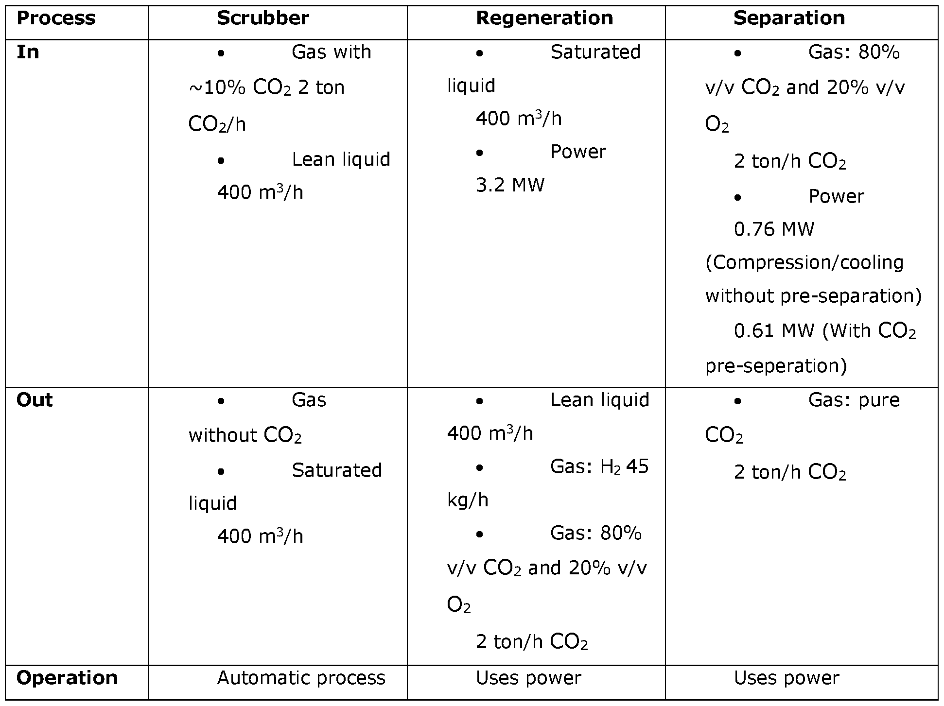
- the carbon capture reaction in the scrubbing step takes place automatically.
- the operation of the scrubber is thereby an automatic process and requires no power apart from one needed to circulate the liquids.
- the regeneration process of the first scrubbing liquid that take place in the cathode and anode chambers of the electrolytic cell are electrochemical reactions, which inherently require electrical power.
- the electrochemical process regenerates the solvent, produces hydrogen at the cathode and a mixture of carbon dioxide (CO2) and oxygen at the anode.
- the regeneration thus comprises generating gaseous hydrogen in the cathode chamber and a gaseous mixture of oxygen and carbon dioxide in the anode chamber by electrolysis.
- the percentages of concentrations of liquids or gas may be defined by % v/v i.e. a volume concentration of a solution, where a solution having 80% CO2 and 20% O2 may be seen as a solution of 100 units of a volume, has 80 units of CO2 and 20 units O2, where the units may be ml, litres,
- At least 60% of the oxygen is removed from the gaseous mixture, or at least 70% of the oxygen is removed from the gaseous mixture, or at least 80 % of the oxygen is removed from the gaseous mixture, or at least 90% of the oxygen is removed from the gaseous mixture, or at least 95% of the oxygen is removed from the gaseous mixture, or at least 99% of the oxygen is removed from the gaseous mixture.
- substantially all of the oxygen may be removed before compression, which even further increased the energy saved during the compression stage.
- the method may further comprise the step of compressing said oxygen depleted gaseous mixture into a substantially pure liquid carbon dioxide.
- the gas having a first carbon dioxide concentration is any one of a flue gas, an exhaustive gas, air.
- the step of treating said gaseous mixture to remove at least 50% oxygen from said mixture comprises: flowing said gaseous mixture through a heating device, thereby consuming said oxygen and creating an output flow of carbon dioxide and dihydrogen oxide (H2O).
- the heating device may be a separate burner, or for instance a generator producing district heating and power, and the full flow of the gaseous mixture of carbon dioxide and oxygen could be used instead of air.
- the carbon dioxide and water may thus be further separated by condensation, and the pure CO2 can be further cleaned, cooled and compressed for transport.
- the heating device may be fed with a fuel, and wherein said fuel is any one of hydrogen, natural gas or biogas and said hydrogen may be a gaseous hydrogen withdrawn from a cathode chamber of said electrolytic cell.
- the step of treating said gaseous mixture to remove at least 50% oxygen from said mixture may comprise utilising said gaseous mixture as an oxidizer in a processes step of scrubbing a flue gas for CO2.
- the flue gas will intermittently consist of pure CO2, which can thus be cooled and compressed directly for transport with limited pre-treatment.
- the step of treating said gaseous mixture to remove at least 50% oxygen from said mixture comprises utilising said gaseous mixture as an oxidizing agent in an aerobic biological treatment process.
- an aerobic biological treatment process for instance a wastewater purification process, and through this treatment the oxygen is depleted during the wastewater purification process and the purified CO2 can be collected, cooled and compressed for transport.
- a gas such as flue gas or exhaustive gas, comprising carbon dioxide to deplete the flue gas of carbon dioxide, the system comprising:
- the regeneration arrangement comprises an electrolytic cell, comprising an anode chamber comprising an anode inlet for receiving the spent aqueous scrubbing liquid and an anode outlet for withdrawing oxygen and carbon dioxide,
- a regeneration arrangement for regenerating a spent aqueous scrubbing liquid to provide alkaline, aqueous scrubbing liquid
- the regeneration arrangement comprising an electrolytic cell, comprising an anode chamber comprising an anode inlet for receiving the spent aqueous scrubbing liquid and an anode outlet for withdrawing oxygen and carbon dioxide, and the cathode chamber comprises an outlet for withdrawing regenerated aqueous scrubbing liquid;
- the gas separator device may be a heating device.
- heating device is meant a device such as a burner, an engine or a generator.
- the gas separator device may be an aerobic biological process facility such as a wastewater treatment plant.
- at least 50% of the oxygen is removed from the gaseous mixture of carbon dioxide and oxygen withdrawn from the anode chamber by or in the gas separator device.
- at least 60% of the oxygen is removed from the gaseous mixture, or at least 70% of the oxygen is removed from the gaseous mixture, or at least 80 % of the oxygen is removed from the gaseous mixture, or at least 90 % of the oxygen is removed from the gaseous mixture, or at least 95 % of the oxygen is removed from the gaseous mixture, or at least 99 % of the oxygen is removed from the gaseous mixture.
- Fig. 1 shows a flow path between a scrubber and an electrolytic cell
- Fig. 2 shows a regeneration arrangement of the process scheme
- Fig. 3 shows a Voltage/Current graph for an electrolytic cell
- Fig. 4 shows a graph showing the CO2 concentration in volume percentage of a CO2 mixture stream exiting the electrolytic cell.
- a system 100 having a scrubber arrangement 200 and a regeneration arrangement 300.
- a method of scrubbing a gas such as flue gas or an exhaustive gas, comprising carbon dioxide CO2 is schematically illustrated.
- the scrubber arrangement 200 and the regeneration arrangement 300 may be operated independently.
- the gas which is scrubbed in the scrubber may for instance be a flue gas or an exhaustive gas.
- One alternative is to utilise the scrubber and regeneration in a vehicle.
- Another option could be so called DAC (direct air capture) applications, where CO2 is captured from the ambient air and a stream of concentrated CO2 is generated.
- the gas enters the scrubber through the scrubber inlet 213.
- the scrubbing method can be described as follows. The gas is scrubbed in the scrubber 210 in a counter flow manner with a first alkaline, aqueous scrubbing liquid to dissolve carbon dioxide CO2 as hydrogen carbonate HCO3- and/or as carbonate CCh 2 ' in the first alkaline, aqueous scrubbing liquid.
- a first spent aqueous scrubbing liquid comprising dissolved hydrogen carbonate HCO3- and/or carbonate CC>3 2 ' results.
- the first spent aqueous scrubbing liquid has a pH from about 7 to about 11, or usually from about 7 to about 9, when it leaves at the outlet 211" for withdrawing spent aqueous scrubbing liquid of the scrubber 210.
- the first spent aqueous scrubbing liquid is then fed to an anode chamber 313 of an electrolytic cell 310 via an anode inlet 313'.
- the electrolytic cell 310 has apart from the anode chamber 313 also a cathode chamber 312.
- the anode chamber 313 and the cathode chamber 312 are separated by a membrane 311.
- This membrane 311 may be semi- permeable membrane, being permeable to cations, but essentially impermeable to anions. Thus, the membrane cation-exchange membrane.
- the electrolysis increases the pH of the first spent aqueous scrubbing liquid in the cathode chamber 312. In the anode chamber 313, the electrolysis further depletes the first spent aqueous scrubbing liquid of hydrogen carbonate HCO3- and of carbonate CC>3 2 ' by decreasing the pH-value to release gaseous carbon dioxide.
- the outlet 211" for spent aqueous scrubbing liquid of the scrubber 210 is in flow communication with the inlet 313' for the spent aqueous scrubbing liquid of the anode chamber 313.
- the outlet 312" for regenerated aqueous scrubbing liquid of the cathode chamber 312 is flow communication with the inlet 212' for the alkaline, aqueous scrubbing liquid of the scrubber 210.
- the first spent aqueous scrubbing liquid is regenerated by generating gaseous hydrogen H2 and dissolved hydroxide ions OH' in the cathode chamber 312 and a gaseous mixture of oxygen O2 and carbon dioxide CO2 in the anode chamber 313 by electrolysis. This is indicated by the upwards pointing arrows from the cathode outlet 312" and the anode outlet 313" in Fig. 1, respectively.
- the gaseous hydrogen H2 and dissolved hydroxide ions OH' are withdrawn from the cathode chamber 312 and the gaseous mixture of oxygen O2 and carbon dioxide CO2 are withdrawn from the anode chamber 313.
- the hydrogen H2 may be used in downstream processes (not shown) such as in fuel or methanol production.
- the regenerated alkaline, aqueous scrubbing liquid from the cathode chamber 312 is then recirculated via the inlet 212' for receiving the alkaline, aqueous scrubbing liquid to the scrubber 210.
- Gas depleted of carbon dioxide CO2 then exits the scrubber 210 via the scrubber outlet 214.
- the gaseous mixture of carbon dioxide and oxygen withdrawn from the anode chamber 313 is transported to a separation device 340, where oxygen is removed from the gaseous mixture, such that a stream of substantially pure gaseous CO2 is obtained.
- the substantially pure gaseous CO2 may then be transferred to a compression unit 330, where the gaseous CO2 is converted into a substantially pure liquid CO2.
- the regeneration arrangement 300 also comprises a first gas separator device 340 for separating oxygen O2 and carbon dioxide CO2 withdrawn from the anode chamber 313 from liquid.
- the first gas separator 340 is arranged upstream the second compressor unit 330.
- the composition of the gaseous mixture is typically around 75% v/v CO2 and 25% v/v O2.
- the oxygen O2 and carbon dioxide CO2 are separated in the first gas separator device 340 leaving a substantially pure gaseous CO2 stream which may be compressed in the first compressor unit 330.
- An advantage of providing CO2 in a liquid phase is that it is practical during transportation. According to the invention oxygen is thus removed from the gaseous mixture before the carbon dioxide is compressed. At least 50% of the oxygen is removed from the gaseous mixture, as this allows for a substantial energy saving when compressing the carbon dioxide into a liquid carbon dioxide.
- At least 60% of the oxygen is removed from said mixture.
- At least 80% of the oxygen is removed from said mixture.
- At least 90% of the oxygen is removed from said mixture.
- At least 95% of the oxygen is removed from said mixture.
- At least 99% of the oxygen is removed from said gaseous mixture.
- the gas separator device 340 may according to one embodiment may be a heating device.
- the heating device may for instance be a burner where the oxygen in the gaseous mixture is used as an oxygen source instead of air, leaving a pure CO2 steam of gas and water which can be collected, cleaned and handled downstream of the separator device.
- the heating device may also be a generator, such as for instance for obtaining central or district heating and power, using either biogas, natural gas or H2 gas as input and the full flow from the anode chamber outlet of the gaseous mixture of CO2/O2 is used as an oxygen source.
- One alternative is to use the H2 gas from the cathode chamber of the electrolyser cell as input.
- the separator device 340 provides the gaseous mixture of carbon dioxide and oxygen as an oxidizer or oxidizing agent in the process where the gas is scrubbed for CO2 if all the oxidant is O2 mixed with CO2 the flue gas will intermittently consist of pure CO2 and it can thus be compressed directly with limited pre-treatment.
- a gas fired generator may be fuelled with methane and a mixture of CO2/O2 instead of air, which leads to the exhaust gas being is pure CO2 and water. The exhaust gas created is therefore pure CO2, as no nitrogen from the air is injected creating NOx and N2 in the exhaust.
- the separator device 340 is a biological aerobic process, such as for instance a wastewater treatment plant, which is either in flow connection to the regeneration arrangement, or where the gaseous mixture of oxygen and carbon dioxide is transported.
- the gaseous mixture is utilised in the wastewater treatment process, such that the oxygen in the gaseous mixture is consumed as an oxidizing agent, for instance through various enzymatic and bacterial reactions in the wastewater process.
- the purified CO2 may then be collected and compressed.
- the regeneration arrangement 300 further comprises a second compressor unit 320 for compressing hydrogen gas withdrawn from the cathode chamber 312.
- the regeneration arrangement 300 also comprises a second gas separator 380 for separating gaseous hydrogen H2 and, for instance, liquid aqueous potassium hydroxide KOH, withdrawn from the cathode chamber 312.
- a second gas separator 380 for separating gaseous hydrogen H2 and, for instance, liquid aqueous potassium hydroxide KOH, withdrawn from the cathode chamber 312.
- the regeneration arrangement 300 has a separator 350, such as a filter.
- the filter may be a reversed osmosis filter.
- This concentrator 350 is arranged downstream of the first gas separator unit 340.
- the electrolytic cell may be sensitive to impurities in the fluid flowing through the anode and cathode chambers.
- there may also be a separate cleaning unit (not shown), which serves to remove impurities such as for instance nitrogen oxides NOx and sulfur oxides SOx from the spent aqueous scrubbing liquid before it enters the electrolytic cell 310.
- the cleaning unit may include a filter to remove particulate matter.
- the direction of the arrows corresponds to the direction of flow of the fluids circulating in the system 100. Further, the lines of the arrows indicate a fluid or flow communication between the elements of the system. Chemical processes
- the solvent is then regenerated in the regeneration arrangement 300 using electrochemistry.
- the electrochemical reaction can be split into two parts; the anode reaction and the cathode reaction. These reactions will be described below.
- O 2 and CO 2 are generated in two different steps. First, O 2 is generated at the anode together with 4 H + . Then, the H+ decreases the pH- value of the solvent and releases CO 2 . Simultaneously, O 2 is generated at the anode and the two gases are mixed in a ratio of 4: 1, CO 2 to O 2 .
- the overall reaction at the anode chamber 313 is:
- the reaction at the anode is:
- the cathode chamber reaction 312 is:
- the electrochemical reaction in the electrolytic cell 310 requires electrical power.
- H2 is typically produced in a ratio of 2: 1. If the downstream application is methanol production, the suitable stoichiometric ratio is 1 :3 and additional H2 is required for this process.
- Commercial electrolysis equipment produces H2 with an energy consumption of 55 kWh/kg.
- the power consumption of the carbon capture process is determined primarily by the electrochemical cell. The purification of CO2 requires additional energy.
- the liquefaction or compression of CO2 requires energy, where the energy may be in the form of electricity for a compressor.
- energy may be in the form of electricity for a compressor.
- CO2 is transported in its liquid state at 15 bars and -30 C.
- the optimized compression and liquefaction of pure CO2 typically has an energy cost of app. 110 wh/kg CO2. If other components are present in the CO2 the cost of compression will increase due to increased volume and weight.
- the CO2 stream exiting system 100 may contain a CO2 and O2 mixture with a CO2 content between 66 % v/v and 80 % v/v, thus the energy required to compress the CO2 stream will be higher than that of pure CO2.
- CO2 contents were measured using a Guardian NG from Edinburgh Sensors. A standard heat plate was used to keep a constant temperature of the liquid at 40 degrees Celsius during the experiments.
- the pH and temperature were measured in the circulation tanks using standard online pH and temperature meters.
- the current density applied to the electrolyser were varied between 1-4 kA/m 2 , using a standard power converter.
- Electrocell that typically is used for KOH and chlorine production.
- the cell was of the type Electro MP Cell, from Electrocell A/S, Vennelystvej 1, DK-6880 Tarm, with the following configuration, the anode being titanium coated with MMO, the cathode being out of a Nickel alloy and the membrane being a National 424 membrane.
- the test was performed on a 0.6 M KHCO3 solution that is equivalent to absorber liquid that is fully loaded with CO2, the absorber liquid is circulated on the anode side of the cell with 1.5 l/min.
- the CO2 content of the absorber liquid is dependent on the effectiveness of the Scrubber, and where the tests have been performed the absorber liquid had absorbed at least 90% of possible CO2 absorption possible by the absorption liquid.
- a 4.5 M KOH is circulated with 1.5 l/min, and the KOH concentration is increased, bleeding out liquid from the cathode is equivalent to lean absorber liquid.
- the temperature of the cell and liquid streams is set to 70 C.
- a voltage is then applied to the cell and increased until a current of 15 A is reached, for full current voltage relation of the cell, as seen in Fig. 3.
- the amount of CO2 released from the anode is measured with a mass flow meter and CO2 sensor, as seen in Fig. 4, which shows the CO2 concentration and the gas flow as a function of time during the current voltage (4V at 15 A) curve performed.
- the flow meter used is of the type of Aalborg GFM gas flow meter and the CO2 meter used is of the type Guardian NG from Edinburgh Sensors.
- the CO2 mixture stream has a CO2 content of about 78 % v/v.
Landscapes
- Chemical & Material Sciences (AREA)
- Engineering & Computer Science (AREA)
- Chemical Kinetics & Catalysis (AREA)
- Oil, Petroleum & Natural Gas (AREA)
- General Chemical & Material Sciences (AREA)
- Analytical Chemistry (AREA)
- Environmental & Geological Engineering (AREA)
- Health & Medical Sciences (AREA)
- Biomedical Technology (AREA)
- Life Sciences & Earth Sciences (AREA)
- Organic Chemistry (AREA)
- Sustainable Development (AREA)
- Electrochemistry (AREA)
- Water Supply & Treatment (AREA)
- Hydrology & Water Resources (AREA)
- Microbiology (AREA)
- Biodiversity & Conservation Biology (AREA)
- Physics & Mathematics (AREA)
- Thermal Sciences (AREA)
- Inorganic Chemistry (AREA)
- Treating Waste Gases (AREA)
- Gas Separation By Absorption (AREA)
- Carbon And Carbon Compounds (AREA)
- Electrolytic Production Of Non-Metals, Compounds, Apparatuses Therefor (AREA)
Abstract
Description
Claims
Priority Applications (6)
| Application Number | Priority Date | Filing Date | Title |
|---|---|---|---|
| AU2023228063A AU2023228063A1 (en) | 2022-03-04 | 2023-03-03 | Electrolytic regeneration of co2 rich alkaline absorbent for co2 recovery |
| KR1020247031397A KR20250005987A (en) | 2022-03-04 | 2023-03-03 | Recovery of carbon dioxide through electrolytic regeneration of carbon dioxide-rich alkaline absorbents |
| CA3244903A CA3244903A1 (en) | 2022-03-04 | 2023-03-03 | Electrolytic regeneration of co2 rich alkaline absorbent for co2 recovery |
| US18/840,651 US20250170518A1 (en) | 2022-03-04 | 2023-03-03 | Method of producing carbon dioxide from a gas scrubbing process |
| EP23707960.3A EP4486483A1 (en) | 2022-03-04 | 2023-03-03 | Electrolytic regeneration of corich alkaline absorbent for co2 rich alkaline absorbent for co2 recovery |
| JP2024550180A JP2025506815A (en) | 2022-03-04 | 2023-03-03 | Electrolytic regeneration of CO2-rich alkaline absorbents for CO2 capture |
Applications Claiming Priority (2)
| Application Number | Priority Date | Filing Date | Title |
|---|---|---|---|
| EP22160299.8A EP4238630A1 (en) | 2022-03-04 | 2022-03-04 | Electrolytic regeneration of co2 rich alkaline absorbent for co2 recovery |
| EP22160299.8 | 2022-03-04 |
Publications (1)
| Publication Number | Publication Date |
|---|---|
| WO2023166166A1 true WO2023166166A1 (en) | 2023-09-07 |
Family
ID=80628875
Family Applications (1)
| Application Number | Title | Priority Date | Filing Date |
|---|---|---|---|
| PCT/EP2023/055416 Ceased WO2023166166A1 (en) | 2022-03-04 | 2023-03-03 | Electrolytic regeneration of co2 rich alkaline absorbent for co2 recovery |
Country Status (7)
| Country | Link |
|---|---|
| US (1) | US20250170518A1 (en) |
| EP (2) | EP4238630A1 (en) |
| JP (1) | JP2025506815A (en) |
| KR (1) | KR20250005987A (en) |
| AU (1) | AU2023228063A1 (en) |
| CA (1) | CA3244903A1 (en) |
| WO (1) | WO2023166166A1 (en) |
Cited By (1)
| Publication number | Priority date | Publication date | Assignee | Title |
|---|---|---|---|---|
| EP4635605A1 (en) | 2024-04-17 | 2025-10-22 | Estech A/S | Co2 capture process with regeneration of scrubber liquid |
Citations (3)
| Publication number | Priority date | Publication date | Assignee | Title |
|---|---|---|---|---|
| US20170107478A1 (en) * | 2015-06-10 | 2017-04-20 | Kevin C. Harmon | System and method for biomass growth and processing |
| CN206799327U (en) * | 2017-03-28 | 2017-12-26 | 中国科学院城市环境研究所 | A kind of ship tail gas and ballast water integrated treatment unit |
| US11219860B1 (en) | 2020-11-06 | 2022-01-11 | Estech A/S | CO2 capture process with electrolytic regeneration |
-
2022
- 2022-03-04 EP EP22160299.8A patent/EP4238630A1/en not_active Withdrawn
-
2023
- 2023-03-03 AU AU2023228063A patent/AU2023228063A1/en active Pending
- 2023-03-03 EP EP23707960.3A patent/EP4486483A1/en active Pending
- 2023-03-03 US US18/840,651 patent/US20250170518A1/en active Pending
- 2023-03-03 KR KR1020247031397A patent/KR20250005987A/en active Pending
- 2023-03-03 JP JP2024550180A patent/JP2025506815A/en active Pending
- 2023-03-03 WO PCT/EP2023/055416 patent/WO2023166166A1/en not_active Ceased
- 2023-03-03 CA CA3244903A patent/CA3244903A1/en active Pending
Patent Citations (3)
| Publication number | Priority date | Publication date | Assignee | Title |
|---|---|---|---|---|
| US20170107478A1 (en) * | 2015-06-10 | 2017-04-20 | Kevin C. Harmon | System and method for biomass growth and processing |
| CN206799327U (en) * | 2017-03-28 | 2017-12-26 | 中国科学院城市环境研究所 | A kind of ship tail gas and ballast water integrated treatment unit |
| US11219860B1 (en) | 2020-11-06 | 2022-01-11 | Estech A/S | CO2 capture process with electrolytic regeneration |
Non-Patent Citations (4)
| Title |
|---|
| LEI M. ET AL: "Thermal Swing Adsorption Process for Carbon Dioxide Capture and Recovery: Modeling, Simulation, Parameters Estimability, and Identification", INDUSTRIAL & ENGINEERING CHEMISTRY RESEARCH, vol. 52, no. 22, 20 May 2013 (2013-05-20), pages 7526 - 7533, XP055946027, ISSN: 0888-5885, DOI: 10.1021/ie3029152 * |
| MORROW R.C. ET AL: "Biomass Production System (BPS) plant growth unit", ADVANCES IN SPACE RESEARCH, vol. 26, no. 2, 1 January 2000 (2000-01-01), AMSTERDAM, NL, pages 289 - 298, XP055947344, ISSN: 0273-1177, DOI: 10.1016/S0273-1177(99)00573-6 * |
| POWER B.: "combined-cycle-carbon-capture-options-and-costs-part-i/ 1/19 ?", 1 June 2009 (2009-06-01), pages 1 - 19, XP055946895, Retrieved from the Internet <URL:https://www.powermag.com/capturing-co2-gas-compression-vs-liquefaction/> [retrieved on 20220727] * |
| WADAS BRIAN: "CO2 CAPTURE AND COMPRESSION TECHNOLOGIES", 1 June 2010 (2010-06-01), pages 1 - 22, XP055946893, Retrieved from the Internet <URL:https://dc.engconfintl.org/cgi/viewcontent.cgi?article=1035&context=co2_summit> [retrieved on 20220727] * |
Cited By (2)
| Publication number | Priority date | Publication date | Assignee | Title |
|---|---|---|---|---|
| EP4635605A1 (en) | 2024-04-17 | 2025-10-22 | Estech A/S | Co2 capture process with regeneration of scrubber liquid |
| WO2025219464A1 (en) | 2024-04-17 | 2025-10-23 | Estech A/S | Co2 capture process with regeneration of scrubber liquid |
Also Published As
| Publication number | Publication date |
|---|---|
| CA3244903A1 (en) | 2023-09-07 |
| KR20250005987A (en) | 2025-01-10 |
| US20250170518A1 (en) | 2025-05-29 |
| JP2025506815A (en) | 2025-03-13 |
| EP4238630A1 (en) | 2023-09-06 |
| AU2023228063A1 (en) | 2024-10-10 |
| EP4486483A1 (en) | 2025-01-08 |
Similar Documents
| Publication | Publication Date | Title |
|---|---|---|
| EP3995204B1 (en) | Co2 capture process with electrolytic regeneration | |
| US20250128204A1 (en) | Reduced reagent regeneration energy for carbon dioxide capture with bipolar membrane electrodialysis, systems and related methods | |
| JP2005052762A (en) | Method and system for treating gas | |
| AU2019302589A1 (en) | Process and system for producing carbon monoxide and dihydrogen from a CO2-containing gas | |
| US20250205644A1 (en) | Method for increased carbon capture in an electrolytic process | |
| JP2004174370A (en) | Method, apparatus and system for treating gas | |
| US7708966B2 (en) | Systems and methods for on-site selective catalytic reduction | |
| JP2004174369A (en) | Gas treatment method and system therefor | |
| US20250170518A1 (en) | Method of producing carbon dioxide from a gas scrubbing process | |
| Mohammadpour et al. | Simple energy-efficient electrochemically-driven CO2 scrubbing for biogas upgrading | |
| CN118751020A (en) | Ship carbon treatment system and control method thereof | |
| JP2846105B2 (en) | Combustion equipment | |
| JP2004176622A (en) | Gas turbine power generation system | |
| CN119367984B (en) | A CO2 direct air capture system and method for increasing CO2 partial pressure | |
| JP2004174371A (en) | Method for treating gas and system therefor | |
| CN118437134B (en) | Direct capture of CO in air using a cooling tower2Method and apparatus of (a) | |
| JP2004307876A (en) | Gas treatment method, and system therefor |
Legal Events
| Date | Code | Title | Description |
|---|---|---|---|
| 121 | Ep: the epo has been informed by wipo that ep was designated in this application |
Ref document number: 23707960 Country of ref document: EP Kind code of ref document: A1 |
|
| WWE | Wipo information: entry into national phase |
Ref document number: 2024550180 Country of ref document: JP Ref document number: 202417063479 Country of ref document: IN |
|
| WWE | Wipo information: entry into national phase |
Ref document number: 18840651 Country of ref document: US |
|
| WWE | Wipo information: entry into national phase |
Ref document number: 814618 Country of ref document: NZ |
|
| WWE | Wipo information: entry into national phase |
Ref document number: AU2023228063 Country of ref document: AU |
|
| WWE | Wipo information: entry into national phase |
Ref document number: 11202405656U Country of ref document: SG |
|
| WWE | Wipo information: entry into national phase |
Ref document number: 2023707960 Country of ref document: EP |
|
| NENP | Non-entry into the national phase |
Ref country code: DE |
|
| ENP | Entry into the national phase |
Ref document number: 2023228063 Country of ref document: AU Date of ref document: 20230303 Kind code of ref document: A |
|
| ENP | Entry into the national phase |
Ref document number: 2023707960 Country of ref document: EP Effective date: 20241004 |
|
| WWP | Wipo information: published in national office |
Ref document number: 18840651 Country of ref document: US |