WO2023163238A2 - 粘着テープ - Google Patents
粘着テープ Download PDFInfo
- Publication number
- WO2023163238A2 WO2023163238A2 PCT/JP2023/023600 JP2023023600W WO2023163238A2 WO 2023163238 A2 WO2023163238 A2 WO 2023163238A2 JP 2023023600 W JP2023023600 W JP 2023023600W WO 2023163238 A2 WO2023163238 A2 WO 2023163238A2
- Authority
- WO
- WIPO (PCT)
- Prior art keywords
- adhesive tape
- release paper
- tape
- distance
- adhesive
- Prior art date
- Legal status (The legal status is an assumption and is not a legal conclusion. Google has not performed a legal analysis and makes no representation as to the accuracy of the status listed.)
- Ceased
Links
Images




Classifications
-
- C—CHEMISTRY; METALLURGY
- C09—DYES; PAINTS; POLISHES; NATURAL RESINS; ADHESIVES; COMPOSITIONS NOT OTHERWISE PROVIDED FOR; APPLICATIONS OF MATERIALS NOT OTHERWISE PROVIDED FOR
- C09J—ADHESIVES; NON-MECHANICAL ASPECTS OF ADHESIVE PROCESSES IN GENERAL; ADHESIVE PROCESSES NOT PROVIDED FOR ELSEWHERE; USE OF MATERIALS AS ADHESIVES
- C09J7/00—Adhesives in the form of films or foils
- C09J7/20—Adhesives in the form of films or foils characterised by their carriers
- C09J7/21—Paper; Textile fabrics
-
- C—CHEMISTRY; METALLURGY
- C09—DYES; PAINTS; POLISHES; NATURAL RESINS; ADHESIVES; COMPOSITIONS NOT OTHERWISE PROVIDED FOR; APPLICATIONS OF MATERIALS NOT OTHERWISE PROVIDED FOR
- C09J—ADHESIVES; NON-MECHANICAL ASPECTS OF ADHESIVE PROCESSES IN GENERAL; ADHESIVE PROCESSES NOT PROVIDED FOR ELSEWHERE; USE OF MATERIALS AS ADHESIVES
- C09J7/00—Adhesives in the form of films or foils
- C09J7/20—Adhesives in the form of films or foils characterised by their carriers
- C09J7/22—Plastics; Metallised plastics
- C09J7/26—Porous or cellular plastics
-
- C—CHEMISTRY; METALLURGY
- C09—DYES; PAINTS; POLISHES; NATURAL RESINS; ADHESIVES; COMPOSITIONS NOT OTHERWISE PROVIDED FOR; APPLICATIONS OF MATERIALS NOT OTHERWISE PROVIDED FOR
- C09J—ADHESIVES; NON-MECHANICAL ASPECTS OF ADHESIVE PROCESSES IN GENERAL; ADHESIVE PROCESSES NOT PROVIDED FOR ELSEWHERE; USE OF MATERIALS AS ADHESIVES
- C09J7/00—Adhesives in the form of films or foils
- C09J7/20—Adhesives in the form of films or foils characterised by their carriers
- C09J7/28—Metal sheet
-
- C—CHEMISTRY; METALLURGY
- C09—DYES; PAINTS; POLISHES; NATURAL RESINS; ADHESIVES; COMPOSITIONS NOT OTHERWISE PROVIDED FOR; APPLICATIONS OF MATERIALS NOT OTHERWISE PROVIDED FOR
- C09J—ADHESIVES; NON-MECHANICAL ASPECTS OF ADHESIVE PROCESSES IN GENERAL; ADHESIVE PROCESSES NOT PROVIDED FOR ELSEWHERE; USE OF MATERIALS AS ADHESIVES
- C09J7/00—Adhesives in the form of films or foils
- C09J7/30—Adhesives in the form of films or foils characterised by the adhesive composition
- C09J7/38—Pressure-sensitive adhesives [PSA]
-
- C—CHEMISTRY; METALLURGY
- C09—DYES; PAINTS; POLISHES; NATURAL RESINS; ADHESIVES; COMPOSITIONS NOT OTHERWISE PROVIDED FOR; APPLICATIONS OF MATERIALS NOT OTHERWISE PROVIDED FOR
- C09J—ADHESIVES; NON-MECHANICAL ASPECTS OF ADHESIVE PROCESSES IN GENERAL; ADHESIVE PROCESSES NOT PROVIDED FOR ELSEWHERE; USE OF MATERIALS AS ADHESIVES
- C09J7/00—Adhesives in the form of films or foils
- C09J7/40—Adhesives in the form of films or foils characterised by release liners
Definitions
- the present invention relates to an adhesive tape provided with a release paper.
- Patent Document 1 As a conventional adhesive tape, there is one described in Patent Document 1, for example.
- the adhesive tape described in the document is a double-faced tape wound around an annular core. Both the front surface and the back surface of this adhesive tape are adhesive surfaces. However, a release paper is attached to the surface of the adhesive tape. Therefore, the adhesive surface is exposed only on the back surface of the adhesive tape.
- This adhesive tape is used while being rotatably held by a tape cutter.
- the tape cutter has a pair of side plate portions (face plates), a bottom plate portion, and a cutting blade.
- the pair of side plate portions covers the adhesive tape from both sides.
- the bottom plate portion is connected to the lower ends of the side plate portions so as to connect the side plate portions.
- a cutting blade is provided at the end of the bottom plate portion.
- the adhesive tape described above is drawn out from the gap between the pair of side plate portions and cut by the cutting blade.
- the release paper is peeled off from the surface.
- the peeled release paper is discharged as waste. It is desirable to recycle paper that is discharged as waste in this way.
- release paper is difficult to recycle because the paper cannot be separated from the resin coating its surface. Therefore, from the viewpoint of SDGs (Sustainable Development Goals), it is necessary to devise ways to reduce the amount of released release paper.
- the present invention has been made in view of the above problems, and an object of the present invention is to provide an adhesive tape that contributes to reducing the amount of release paper discharged.
- the adhesive tape according to the present invention comprises a tape body having a first surface which is an adhesive surface, and a release paper attached to the first surface, wherein the width of the release paper is greater than the width of the tape body. and the first distance, which is the distance from the release liner to the first side edge of the tape body, is less than the second distance, which is the distance from the release liner to the second side edge of the tape body. is also large.
- This adhesive tape is provided with a tape body whose first surface is an adhesive surface.
- a release paper is attached to the first surface of the tape body.
- the width of the release paper is smaller than the width of the tape body. In this case, compared to the case where the width of the release paper is equal to the width of the tape body, the amount of release paper discharged can be reduced.
- an adhesive tape that contributes to reducing the amount of release paper discharged is realized.
- FIG. 1 is a side view showing one embodiment of an adhesive tape according to the present invention
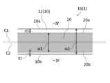
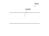
- FIG. FIG. 2 is a plan view showing a lead-out portion 1b of the adhesive tape of FIG. 1; It is a bottom view which shows the drawer part 1b of the adhesive tape of FIG.
- FIG. 1 is a side view showing one embodiment of the adhesive tape according to the present invention.
- the adhesive tape 1 is wound.
- the adhesive tape 1 may be wound around an annular core, or may be wound without such a core.
- the adhesive tape 1 consists of a wound portion 1a and a lead portion 1b.
- the wound portion 1a is a wound portion of the adhesive tape 1.
- the drawn-out portion 1b is a portion of the adhesive tape 1 drawn out from the winding portion 1a.
- the adhesive tape 1 has a tape body 10 and a release paper 20 .
- the tape body 10 has a front surface 12 (first surface) and a back surface 14 (second surface).
- Surface 12 is an adhesive surface.
- the entire surface 12 is the adhesive surface.
- the adhesive tape 1 is a single-sided adhesive tape. That is, of the front surface 12 and the back surface 14, only the front surface 12 is the adhesive surface. Examples of the single-sided adhesive tape include cellophane tape, gap tape, non-slip tape, anti-condensation tape, and the like.
- the tape body 10 has a base material and an adhesive layer provided on the base material. Such an adhesive layer constitutes the adhesive surface described above.
- the substrate consists of, for example, cellophane, felt, sponge, or aluminum.
- the thickness t1 (see FIG. 4) of the tape body 10 may be different from or equal to the thickness t2 of the release paper 20. As shown in FIG. In the former case, the thickness t1 may be larger or smaller than the thickness t2.
- the release paper 20 is attached to the surface 12 of the tape body 10 .
- Release paper 20 is applied to only a portion of surface 12 . That is, the release paper 20 is attached only to a part of the adhesive surface of the surface 12 .
- the width w1 (see FIG. 2) of the release paper 20 is smaller than the width w2 of the tape body 10.
- the release paper 20 is attached only to a portion of the surface 12 in the width direction of the tape body 10 (vertical direction in FIGS. 2 and 3).
- the width direction of the tape body 10 is a direction perpendicular to the extending direction of the tape body 10 (horizontal direction in FIGS. 2 and 3).
- the release paper 20 overlaps the center line C1 of the tape body 10. However, the center line C2 of the release paper 20 does not coincide with the center line C1 in plan view.
- the center line C1 and the center line C2 are imaginary straight lines that bisect the tape body 10 and the release paper 20 in the width direction, respectively.
- the release paper 20 is continuously attached to the surface 12 in the extending direction of the tape body 10 . That is, the release paper 20 is attached to the entire surface 12 in the extending direction of the tape body 10 .
- the entire release paper 20 consists of one continuous piece of release paper.
- the release paper 20 is separated from both the side edge 10a (first side edge) and the side edge 10b (second side edge) of the tape body 10.
- the distance d1 (first distance) from the release liner 20 to the side edge 10a is greater than the distance d2 (second distance) from the release liner 20 to the side edge 10b.
- the distance d1 is equal to the distance between the side edge 20a (the side edge closer to the side edge 10a) of the release paper 20 and the side edge 10a in plan view.
- the distance d2 is equal to the distance between the side edge 20b (the side edge closer to the side edge 10b) of the release paper 20 and the side edge 10b in plan view.
- the difference between the distance d1 and the distance d2 is preferably 2 mm or more, more preferably 5 mm or more.
- the distance d1 is preferably twice or more the thickness t2 of the release paper 20.
- the distance d2 is also preferably at least twice the thickness t2.
- Both the distance d1 and the distance d2 are preferably 2 mm or more and 10 mm or less.
- the width w1 of the release paper 20 is preferably greater than the sum of the distances d1 and d2.
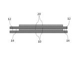
- FIG. 5 is a view showing part of the end face of the winding portion 1a.
- the figure shows an end surface perpendicular to the extending direction of the tape body 10 .
- a portion of the tape body 10 overlaps another portion of the tape body 10 with the release paper 20 interposed therebetween.
- the front surface 12 and the back surface 14 face each other at locations where the release paper 20 is not interposed. However, the facing surface 12 and back surface 14 are not in contact with each other.
- the pressure-sensitive adhesive tape 1 is configured so that the front surface 12 does not come into contact with the back surface 14 facing the front surface 12 in the wound state.
- Such a configuration can be realized by adjusting factors such as the rigidity of the tape body 10, the thickness t2 of the release paper 20, and the distances d1 and d2.
- the adhesive tape 1 is provided with a tape body 10 having an adhesive surface 12 .
- a release paper 20 is attached to the surface 12 of the tape body 10 .
- the width w1 of the release paper 20 is smaller than the width w2 of the tape body 10. - ⁇ In this case, the discharge amount of the release paper 20 can be reduced compared to the case where the width w1 is equal to the width w2. Therefore, an adhesive tape 1 that contributes to a reduction in the amount of release paper 20 discharged is realized.
- the width w1 of the release paper 20 is smaller than the width w2 of the tape body 10, it is possible to align the adhesive tape 1 with respect to the adherend before peeling off the release paper 20 from the surface 12. .
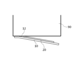
- Such alignment can be performed, for example, as follows. As shown in FIG. 6, the portion of the surface 12 to which the release liner 20 is not attached (the portion between the release liner 20 and the side edge 10a or the portion between the release liner 20 and the side edge 10b) is adhered. It is attached (temporarily attached) to the body 90 . At this time, it is checked whether the position of the tape body 10 is shifted. After the position of the tape body 10 is determined, the release paper 20 is peeled off from the tape body 10 as shown in FIG.
- the adhesive tape 1 can be aligned while the release paper 20 is still attached to the surface 12 . Moreover, since the width w1 of the release liner 20 is smaller than the width w2 of the tape body 10, the release liner 20 can be easily peeled off after alignment.
- Providing the release paper 20 in this manner provides the following advantages. First, it becomes possible to let out the adhesive tape 1 without touching the adhesive surface of the surface 12 of the tape body 10 . As a result, the adhesive tape 1 can be easily pulled, and fingerprints are less likely to adhere to the surface 12. ⁇ In addition, it is possible to suppress the adhesion of dust to the adhesive surface of the surface 12 and the decrease in the adhesive strength of the adhesive surface. Furthermore, since the shape of the tape body 10 is stabilized, the tape body 10 is less likely to twist. Thereby, the adhesive tape 1 can be fed out smoothly.
- a larger width w1 of the release liner 20 is advantageous for fully enjoying the above-described advantages of providing the release liner 20 .
- the width w1 is preferably larger than the sum of the distance d1 and the distance d2.
- the distance d1 from the release paper 20 to the side edge 10a is greater than the distance d2 from the release paper 20 to the side edge 10b.
- the width of the portion (first portion) between the release liner 20 and the side edge 10a on the surface 12 and the width of the portion (second portion) between the release liner 20 and the side edge 10b are different.
- the flexibility of alignment of the adhesive tape 1 with respect to the adherend can be increased. That is, when aligning the pressure-sensitive adhesive tape 1, it is possible to select one of the first and second portions that is more suitable for temporary fixing according to the size, shape, etc. of the adherend.
- a larger difference between the distance d1 and the distance d2 is advantageous in increasing the degree of freedom in positioning the adhesive tape 1.
- the difference between the distance d1 and the distance d2 is preferably 2 mm or more, more preferably 5 mm or more.
- the distance d1 is not sufficiently large with respect to the thickness t2 of the release paper 20, the release paper 20 may become an obstacle, making it difficult to temporarily fix the first portion of the surface 12 to the adherend. From this point of view, the distance d1 is preferably at least twice the thickness t2.
- a larger distance d1 is advantageous for stably temporarily fixing the first portion of the surface 12 to the adherend.
- the distance d1 is preferably 2 mm or more.
- the distance d1 is preferably 10 mm or less.
- the distance d2 is not sufficiently large with respect to the thickness t2 of the release paper 20, the release paper 20 may become an obstacle, making it difficult to temporarily fix the second portion of the surface 12 to the adherend. From this point of view, the distance d2 is preferably at least twice the thickness t2.
- a larger distance d2 is advantageous for stably temporarily fixing the second portion of the surface 12 to the adherend.
- the distance d2 is preferably 2 mm or more.
- the distance d2 is preferably 10 mm or less.
- the release paper 20 is separated from both the side edge 10a and the side edge 10b of the tape body 10.
- the side edge 20a of the release paper 20 is shifted from the side edge 10a
- the side edge 20b of the release paper 20 is shifted from the side edge 10b. Therefore, the release paper 20 can be easily peeled off from either the side edge 20a or the side edge 20b.
- the side edge 20b is peeled off
- the side edge 20a is peeled off.
- the entire release paper 20 consists of one release paper piece.
- the entire release liner 20 can be removed from the surface 12 by peeling off the release liner 20 only once.
- the release paper 20 is continuously attached to the surface 12 in the extending direction of the tape body 10 .
- the lead-out portion 1b of the adhesive tape 1 is less likely to loosen. This makes it difficult for the adhesive surfaces of the drawer portion 1b to adhere to each other.
- the release paper 20 overlaps the center line C1 of the tape body 10. This makes it difficult for fingers to touch the adhesive surface of the surface 12 when the portion of the tape body 10 at the center line C1 is pinched.
- the adhesive tape 1 can be smoothly fed out by pinching and pulling the portion of the center line C1.
- the entire surface 12 of the tape body 10 is an adhesive surface. As a result, the adhesive tape 1 can be stably attached to the adherend.
- the tape body 10 When the thickness t1 of the tape body 10 is greater than the thickness t2 of the release paper 20, the tape body 10 is less likely to bend. Therefore, after peeling off the release paper 20, it is difficult to apply the tape body 10 to the adherend little by little while aligning the positions. Therefore, the adhesive tape 1 that can be aligned even when the release paper 20 is stuck to the surface 12 is particularly useful.
- the tape body 10 When the base material of the tape body 10 is made of felt, sponge or aluminum, the tape body 10 is less likely to be freely deformed than when the base material is cellophane. Therefore, after peeling off the release paper 20, it is difficult to apply the tape body 10 to the adherend little by little while aligning the positions. Therefore, the adhesive tape 1 that can be aligned even when the release paper 20 is stuck to the surface 12 is particularly useful.
- the adhesive tape 1 is a single-sided adhesive tape.
- the surface (surface 12) to which the release paper 20 is attached is first attached to the adherend. Therefore, the adhesive tape 1 that can be aligned even when the release paper 20 is stuck to the surface 12 is particularly useful.
- the adhesive tape 1 is wound. In this case, compared to the case where the adhesive tape 1 is not wound, it is possible to suppress the adhesion of dust to the portion of the surface 12 to which the release paper 20 is not attached and the drying of the portion. can.
- the adhesive tape 1 is configured so that the surface 12 does not come into contact with the back surface 14 facing the surface 12 in the wound state.
- the problem is that if the front surface 12 contacts the back surface 14, the adhesive strength of the adhesive surface of the front surface 12 may be reduced. Such a problem becomes particularly conspicuous when the base material of the tape body 10 is made of felt or sponge. In this regard, the above problem can be avoided by using the adhesive tape 1 configured so that the front surface 12 does not come into contact with the back surface 14 .
- the present invention is not limited to the above embodiments, and various modifications are possible.
- the release paper 20 may be spaced from the side edge 10a and not spaced from the side edge 10b, as shown in FIG. 10, for example. That is, the side edge 20b of the release paper 20 may be aligned with the side edge 10b. In that case, the distance d2 from the release paper 20 to the side edge 10b is zero.
- the release paper 20 overlaps the center line C1 of the tape body 10 as well.
- the case where the entire surface 12 of the tape body 10 is an adhesive surface is exemplified.
- only a portion of surface 12 may be an adhesive surface.
- the release paper 20 is attached only to a portion of the adhesive surface of the surface 12 .
- the adhesive tape 1 is a single-sided adhesive tape
- the adhesive tape 1 may be a double-sided adhesive tape (double-sided tape) in which both the front surface 12 and the back surface 14 are adhesive surfaces.
- the release paper 20 may be attached to the back surface 14 of the tape body 10 .
- the back surface 14 corresponds to the "first surface”
- the front surface 12 corresponds to the "second surface”.
Landscapes
- Chemical & Material Sciences (AREA)
- Organic Chemistry (AREA)
- Adhesive Tapes (AREA)
Priority Applications (2)
| Application Number | Priority Date | Filing Date | Title |
|---|---|---|---|
| JP2023539747A JP7506954B2 (ja) | 2023-06-26 | 2023-06-26 | 粘着テープ |
| PCT/JP2023/023600 WO2023163238A2 (ja) | 2023-06-26 | 2023-06-26 | 粘着テープ |
Applications Claiming Priority (1)
| Application Number | Priority Date | Filing Date | Title |
|---|---|---|---|
| PCT/JP2023/023600 WO2023163238A2 (ja) | 2023-06-26 | 2023-06-26 | 粘着テープ |
Publications (2)
| Publication Number | Publication Date |
|---|---|
| WO2023163238A2 true WO2023163238A2 (ja) | 2023-08-31 |
| WO2023163238A3 WO2023163238A3 (ja) | 2023-10-19 |
Family
ID=87766277
Family Applications (1)
| Application Number | Title | Priority Date | Filing Date |
|---|---|---|---|
| PCT/JP2023/023600 Ceased WO2023163238A2 (ja) | 2023-06-26 | 2023-06-26 | 粘着テープ |
Country Status (2)
| Country | Link |
|---|---|
| JP (1) | JP7506954B2 (https=) |
| WO (1) | WO2023163238A2 (https=) |
Family Cites Families (8)
| Publication number | Priority date | Publication date | Assignee | Title |
|---|---|---|---|---|
| JPS59153337U (ja) * | 1983-03-30 | 1984-10-15 | 日東電工株式会社 | 両面粘着テ−プの巻回構造 |
| JPS61191445U (https=) * | 1985-05-18 | 1986-11-28 | ||
| JPS62124177A (ja) * | 1985-11-22 | 1987-06-05 | Yoshikazu Kimura | 接着テ−プ |
| JPH0330242U (https=) * | 1989-08-03 | 1991-03-25 | ||
| JP2012087195A (ja) | 2010-10-19 | 2012-05-10 | Kuninori Kondo | 施工性の優れた防水テープ |
| JP6293493B2 (ja) | 2014-01-16 | 2018-03-14 | 紫朗 高梨 | 粘着シート |
| JP2017082192A (ja) | 2015-10-29 | 2017-05-18 | 株式会社秀カンパニー | 養生用粘着テープ及びそれを用いた養生方法 |
| JP7604040B2 (ja) * | 2023-03-27 | 2024-12-23 | 株式会社無有 | 両面テープ及びテープカッター |
-
2023
- 2023-06-26 WO PCT/JP2023/023600 patent/WO2023163238A2/ja not_active Ceased
- 2023-06-26 JP JP2023539747A patent/JP7506954B2/ja active Active
Also Published As
| Publication number | Publication date |
|---|---|
| WO2023163238A3 (ja) | 2023-10-19 |
| JP7506954B2 (ja) | 2024-06-27 |
| JPWO2023163238A1 (https=) | 2023-08-31 |
Similar Documents
| Publication | Publication Date | Title |
|---|---|---|
| WO2024022077A1 (zh) | 显示面板和显示装置 | |
| JPS61223080A (ja) | 二重表面粘着テ−プ及びその製造方法 | |
| CN115394187B (zh) | 支撑膜组、显示面板及其制备方法 | |
| US11541632B2 (en) | Protective film and method for peeling release layer thereof | |
| WO2023163238A2 (ja) | 粘着テープ | |
| JP2017161575A (ja) | 治具、および、システム | |
| JP5356449B2 (ja) | ナイフエッジおよびこれを含む液晶表示装置の製造システム | |
| JP2015174318A (ja) | シート積層体 | |
| CN213400344U (zh) | 柔性屏模组及显示装置 | |
| WO2018201312A1 (zh) | 背光模块及显示设备 | |
| CN113593415A (zh) | 显示模组及其制作方法 | |
| CN212687954U (zh) | 曲面屏保护膜 | |
| WO2023136365A2 (ja) | 粘着テープ | |
| CN115926671B (zh) | 一种保护膜、显示模组以及显示设备 | |
| WO2023090464A2 (ja) | 両面テープ及びテープカッター | |
| JP6865048B2 (ja) | クッションテープ | |
| CN223522460U (zh) | 一种避免粘贴不良的大尺寸立体保护膜 | |
| CN209854043U (zh) | 泡棉胶组件 | |
| CN219929962U (zh) | 一种热熔胶双面胶带 | |
| JP5046785B2 (ja) | 貼り付けテープ | |
| TWI819913B (zh) | 膠帶 | |
| JP2014088520A (ja) | 粘着テープおよびその貼り付け方法 | |
| JP7350410B2 (ja) | テープカッター | |
| JP3732948B2 (ja) | コーナー外壁およびコーナーテープ貼り装置 | |
| CN117116151B (zh) | 显示模组和显示装置 |
Legal Events
| Date | Code | Title | Description |
|---|---|---|---|
| ENP | Entry into the national phase |
Ref document number: 2023539747 Country of ref document: JP Kind code of ref document: A |
|
| 121 | Ep: the epo has been informed by wipo that ep was designated in this application |
Ref document number: 23760236 Country of ref document: EP Kind code of ref document: A2 |
|
| NENP | Non-entry into the national phase |
Ref country code: DE |