WO2023157511A1 - 発振器および電気機器 - Google Patents
発振器および電気機器 Download PDFInfo
- Publication number
- WO2023157511A1 WO2023157511A1 PCT/JP2023/000451 JP2023000451W WO2023157511A1 WO 2023157511 A1 WO2023157511 A1 WO 2023157511A1 JP 2023000451 W JP2023000451 W JP 2023000451W WO 2023157511 A1 WO2023157511 A1 WO 2023157511A1
- Authority
- WO
- WIPO (PCT)
- Prior art keywords
- stage device
- final stage
- oscillator
- output
- power
- Prior art date
- Legal status (The legal status is an assumption and is not a legal conclusion. Google has not performed a legal analysis and makes no representation as to the accuracy of the status listed.)
- Ceased
Links
Images


Classifications
-
- H—ELECTRICITY
- H05—ELECTRIC TECHNIQUES NOT OTHERWISE PROVIDED FOR
- H05B—ELECTRIC HEATING; ELECTRIC LIGHT SOURCES NOT OTHERWISE PROVIDED FOR; CIRCUIT ARRANGEMENTS FOR ELECTRIC LIGHT SOURCES, IN GENERAL
- H05B6/00—Heating by electric, magnetic or electromagnetic fields
- H05B6/64—Heating using microwaves
- H05B6/66—Circuits
- H05B6/68—Circuits for monitoring or control
- H05B6/686—Circuits comprising a signal generator and power amplifier, e.g. using solid state oscillators
-
- H—ELECTRICITY
- H03—ELECTRONIC CIRCUITRY
- H03F—AMPLIFIERS
- H03F1/00—Details of amplifiers with only discharge tubes, only semiconductor devices or only unspecified devices as amplifying elements
- H03F1/30—Modifications of amplifiers to reduce influence of variations of temperature or supply voltage or other physical parameters
-
- H—ELECTRICITY
- H03—ELECTRONIC CIRCUITRY
- H03F—AMPLIFIERS
- H03F1/00—Details of amplifiers with only discharge tubes, only semiconductor devices or only unspecified devices as amplifying elements
- H03F1/52—Circuit arrangements for protecting such amplifiers
-
- H—ELECTRICITY
- H03—ELECTRONIC CIRCUITRY
- H03F—AMPLIFIERS
- H03F3/00—Amplifiers with only discharge tubes or only semiconductor devices as amplifying elements
- H03F3/189—High-frequency amplifiers, e.g. radio frequency amplifiers
- H03F3/19—High-frequency amplifiers, e.g. radio frequency amplifiers with semiconductor devices only
- H03F3/195—High-frequency amplifiers, e.g. radio frequency amplifiers with semiconductor devices only in integrated circuits
-
- H—ELECTRICITY
- H03—ELECTRONIC CIRCUITRY
- H03F—AMPLIFIERS
- H03F3/00—Amplifiers with only discharge tubes or only semiconductor devices as amplifying elements
- H03F3/20—Power amplifiers, e.g. Class B amplifiers, Class C amplifiers
- H03F3/24—Power amplifiers, e.g. Class B amplifiers, Class C amplifiers of transmitter output stages
- H03F3/245—Power amplifiers, e.g. Class B amplifiers, Class C amplifiers of transmitter output stages with semiconductor devices only
-
- H—ELECTRICITY
- H03—ELECTRONIC CIRCUITRY
- H03F—AMPLIFIERS
- H03F3/00—Amplifiers with only discharge tubes or only semiconductor devices as amplifying elements
- H03F3/72—Gated amplifiers, i.e. amplifiers which are rendered operative or inoperative by means of a control signal
-
- H—ELECTRICITY
- H05—ELECTRIC TECHNIQUES NOT OTHERWISE PROVIDED FOR
- H05B—ELECTRIC HEATING; ELECTRIC LIGHT SOURCES NOT OTHERWISE PROVIDED FOR; CIRCUIT ARRANGEMENTS FOR ELECTRIC LIGHT SOURCES, IN GENERAL
- H05B6/00—Heating by electric, magnetic or electromagnetic fields
- H05B6/64—Heating using microwaves
- H05B6/70—Feed lines
- H05B6/705—Feed lines using microwave tuning
-
- H—ELECTRICITY
- H05—ELECTRIC TECHNIQUES NOT OTHERWISE PROVIDED FOR
- H05B—ELECTRIC HEATING; ELECTRIC LIGHT SOURCES NOT OTHERWISE PROVIDED FOR; CIRCUIT ARRANGEMENTS FOR ELECTRIC LIGHT SOURCES, IN GENERAL
- H05B6/00—Heating by electric, magnetic or electromagnetic fields
- H05B6/64—Heating using microwaves
- H05B6/72—Radiators or antennas
-
- H—ELECTRICITY
- H03—ELECTRONIC CIRCUITRY
- H03F—AMPLIFIERS
- H03F2200/00—Indexing scheme relating to amplifiers
- H03F2200/451—Indexing scheme relating to amplifiers the amplifier being a radio frequency amplifier
-
- H—ELECTRICITY
- H03—ELECTRONIC CIRCUITRY
- H03F—AMPLIFIERS
- H03F2200/00—Indexing scheme relating to amplifiers
- H03F2200/468—Indexing scheme relating to amplifiers the temperature being sensed
-
- H—ELECTRICITY
- H03—ELECTRONIC CIRCUITRY
- H03F—AMPLIFIERS
- H03F2200/00—Indexing scheme relating to amplifiers
- H03F2200/531—Indexing scheme relating to amplifiers the temperature difference between different chips being controlled
Definitions
- the present disclosure relates to an oscillator that generates output power and provides microwaves corresponding to the output power as output waves, and electronic equipment that includes this oscillator.
- Patent Document 1 a device that emits microwaves to a heating object is known (see Patent Document 1, for example).
- Patent Literature 1 describes an RF energy emitting device that includes a cavity for housing an object to be heated, an RF signal generator, an RF amplifier, and a temperature sensor.
- the RF signal generator oscillates an RF (radio frequency) signal.
- the RF amplifier amplifies the RF signal and outputs RF energy (microwaves).
- a temperature sensor is placed in the vicinity of the RF amplifier.
- An object of the present disclosure is to provide an oscillator and an electrical device that can more accurately detect the temperature of the final-stage device of the RF amplifier.
- An oscillator generates output power and provides microwaves corresponding to the output power as output waves.
- the oscillator of this aspect includes a signal generator, a power amplifier, and a temperature sensor.
- a signal generator generates an oscillation signal.
- the power amplifier amplifies the oscillating signal to generate output power.
- a power amplifier includes a final stage device. The final stage device is packaged. A temperature sensor is provided in the package containing the final stage device.
- An electrical device includes the oscillator, an antenna for radiating an output wave provided by the oscillator, and a cavity for housing an object to be heated.
- the electric appliance of this aspect is, for example, a microwave oven.
- the temperature of the final-stage device can be detected more accurately, and the generation of microwaves can be controlled more accurately.
- FIG. 1 is a block diagram showing the configuration of an oscillator according to Embodiment 1 of the present disclosure.
- FIG. 2 is a block diagram showing a configuration of an electrical device including an oscillator according to Embodiment 1.
- FIG. 3 is a schematic diagram showing the arrangement of final-stage devices and temperature sensors in the oscillator according to the first embodiment.
- FIG. 4 is a schematic diagram showing the arrangement of final-stage devices and temperature sensors in the oscillator according to the first modification of the first embodiment.
- FIG. 5 is a schematic diagram showing the arrangement of final-stage devices and temperature sensors in the oscillator according to the second modification of the first embodiment.
- FIG. 6 is a block diagram showing the configuration of an oscillator according to Embodiment 2 of the present disclosure.
- FIG. 7 is a block diagram showing the configuration of an oscillator according to Embodiment 3 of the present disclosure.
- FIG. 8 is a schematic diagram showing the arrangement of final-stage devices, temperature sensors, and switching units in the oscillator according to the third embodiment.
- FIG. 9 is a schematic diagram showing an example in which the final stage device and the switching section in the oscillator according to the third embodiment are provided on the same IC (integrated circuit) chip.
- FIG. 10 is a block diagram showing the configuration of an oscillator according to Embodiment 4 of the present disclosure.
- 11 is a diagram showing the relationship between the temperature rise and the reflected power stored in the storage unit in the oscillator according to Embodiment 4.
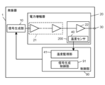
- FIG. 1 is a block diagram showing the configuration of an oscillator 1 according to Embodiment 1.
- FIG. 2 is a block diagram showing the configuration of an electric device 2 that includes the oscillator 1 according to Embodiment 1.
- FIG. 3 is a schematic diagram showing the arrangement of final-stage device 22 and temperature sensor 40 in oscillator 1 according to the first embodiment.
- the electric device 2 is a microwave oven 2a that performs microwave heating on an object to be heated, such as woody biomass, ceramics, ceramic products, or food.
- An oscillator 1 is arranged inside a microwave oven 2a to provide microwaves.
- the oscillator 1 includes a signal generator 10, a power amplifier 20, an output terminal 30, and a controller 90.
- the signal generator 10 generates and outputs an oscillation signal.
- Power amplifier 20 amplifies the oscillation signal to generate output power.
- Power amplifier 20 includes temperature sensor 40 .
- the controller 90 controls the signal generator 10 .
- the power amplifier 20 has a device group 21 and a final stage device 22 .
- the final stage device 22 and the device group 21 are packaged separately.
- a temperature sensor 40 is provided in the package containing the final stage device 22 . According to this configuration, the temperature of the final stage device 22 can be detected more accurately by the temperature sensor 40 arranged in the package including the final stage device 22 .
- the microwave oven 2a includes an oscillator 1, an antenna 100, and a cavity 3 for housing an object to be heated.
- the antenna 100 radiates microwaves corresponding to the output power into the cavity 3 as output waves.
- an antenna 100 is disclosed as an example of a component for radiating microwaves.
- the component for radiating microwaves is not limited to antenna 100 .
- radiation Any configuration that can output or radiate microwaves as a portion may be used.
- the microwave oven 2a includes one or more (two in FIG. 2) oscillators 1 and one or more (two in FIG. 2) antennas 100.
- One or more antennas 100 are associated with one or more oscillators 1, respectively.
- the microwave oven 2a comprises a cavity 3 for housing an object to be heated.
- One or more antennas 100 are all arranged in the cavity 3.
- Oscillator 1 generates and supplies output power to one or more antennas 100 .
- the antenna 100 radiates microwaves corresponding to the output power into the cavity 3 as output waves. Thereby, the microwave oven 2a heats the object to be heated (for example, food) accommodated in the cavity 3 .
- one or more oscillators 1 are associated with one or more antennas 100, respectively.
- the present disclosure is not limited to this configuration. Multiple oscillators 1 may be provided and some or all of the outputs of the multiple oscillators may be combined and fed to fewer antennas 100 than oscillators 1 .
- Some of the outputs of one or more oscillators 1 may be distributed to feed more antennas 100 than oscillators 1 .
- a switch or the like may be provided at the contact point between the oscillator 1 and the antenna 100, and an antenna to which the oscillation signal from the oscillator 1 is supplied may be selected.
- the antenna 100 is not an essential component.
- a waveguide is arranged for transmitting the output power to the cavity 3 , the waveguide may radiate the microwaves into the cavity 3 .
- the signal generator 10 is a semiconductor oscillator and can control the frequency of the oscillation signal.
- the signal generator 10 includes, for example, a quadrature modulation circuit, and can perform phase control of the oscillation signal. Furthermore, the signal generator 10 can control the amplitude of the oscillation signal.
- Optiation signal frequency control means generating an oscillation signal with an arbitrary frequency in a predetermined frequency band.
- Phase control of the oscillation signal means changing the phase of the oscillation signal.
- Amplitude control of the oscillation signal means changing the amplitude of the oscillation signal.
- the signal generation unit 10 may be able to perform all of frequency control, phase control, and amplitude control, or at least one of them.
- the power amplifier 20 amplifies the oscillation signal from the signal generator 10 and outputs output power.
- Power amplifier 20 has device group 21 including a plurality of devices, final stage device 22 arranged at the final stage of power amplifier 20 , and temperature sensor 40 .
- a plurality of devices included in the device group 21 and the final stage device 22 are, for example, transistors.
- the oscillator 1 is a so-called amplifier type oscillator including a device group 21 and a final stage device 22 .
- the device group 21 is connected to the signal generator 10 and the final stage device 22 .
- the final stage device 22 is an ⁇ -type, ⁇ -type, ⁇ -type, and ⁇ -type gallium oxide device.
- the final stage device 22 is connected to the output terminal 30 .
- the final stage device 22 further amplifies the oscillation signal amplified by the device group 21 and supplies output power (microwaves) to the antenna 100 via the output terminal 30 .
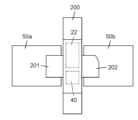
- the final stage device 22 is contained in a package 200, which is a packaged electronic component.
- the package 200 is connected to the electric circuit 50a and the electric circuit 50b.
- the electric lines 50a and 50b are, for example, microstrip lines.
- the electric circuit 50a is connected to the device group 21.
- the electric circuit 50 b is connected to the output terminal 30 .
- a terminal 201 of the package 200 is connected to the electric circuit 50a.
- a terminal 202 of the package 200 is connected to the electric line 50b.
- the input terminal of the final stage device 22 is connected to the terminal 201 . That is, the input terminal of the final stage device 22 is connected to the electric line 50a via the terminal 201.
- FIG. An output terminal of the final stage device 22 is connected to the terminal 202 . That is, the output terminal of the final stage device 22 is connected to the electric line 50b via the terminal 202.
- the package 200 and packaging need not necessarily be walled or encapsulated in plastic or the like to be mounted.
- the package 200 and packaging includes a structure mounted on a printed circuit board or a heat sink as a so-called bare chip.
- Some of the devices included in the device group 21 may be included in the package including the final stage device 22 .
- the final stage device 22 is not limited to gallium oxide (Ga 2 O 3 ) devices.
- the final stage device 22 is a laterally diffused metal-oxide-semiconductor (LDMOS) transistor, gallium arsenide (GaAs), tin oxide ( SnO2 ), diamond (C), indium oxide ( In2O3 ), any of germanium dioxide (GeO 2 ), tin germanium oxide (SnGeO 2 ), gallium indium oxide ((GaIn) 2 O 3 ), gallium nitride (GaN), and aluminum gallium oxide ((AlGa) 2 O 3 ) It may be a configured device.
- LDMOS laterally diffused metal-oxide-semiconductor
- the power amplifier 20 may be arranged between the signal generator 10 and the device group 21 and have a matching circuit for impedance matching between the signal generator 10 and the device group 21 .
- the power amplifier 20 may be arranged between the device group 21 and the final stage device 22 and have a matching circuit for impedance matching between the device group 21 and the final stage device 22 .
- the power amplifier 20 is arranged between the final stage device 22 and the output terminal 30, and the final stage device 22, the output terminal 30, and a component (for example, the antenna 100) connected via the output terminal 30.
- a matching circuit may be provided for impedance matching.
- the output terminal 30 is arranged between the power amplifier 20 and the antenna 100 and connected to the power amplifier 20 and the antenna 100 .
- the output terminal 30 outputs the output power (microwave) from the final stage device 22 of the power amplifier 20 to the antenna 100 .
- the final stage device 22 and the temperature sensor 40 are included in the package 200.
- the temperature sensor 40 detects the temperature of the final stage device 22 and outputs the detected temperature to the control section 90 .
- the temperature of the final stage device 22 detected by the temperature sensor 40 may simply be referred to as the detected temperature.
- the control unit 90 is a computer system having a processor and memory.
- the computer system functions as the control unit 90 by the processor executing programs stored in the memory.
- the program executed by the processor is recorded in advance in the memory of the computer system.
- this program may be recorded in a non-volatile recording medium such as a memory card and provided, or may be provided through an electric communication line such as the Internet.
- control unit 90 has the functions of the temperature monitoring unit 41 and the signal generation control unit 91 .
- the temperature monitoring unit 41 receives the temperature detected by the temperature sensor 40 and monitors this detected temperature.
- the signal generation control unit 91 causes the signal generation unit 10 to perform at least one of frequency control, phase control, and amplitude control of the oscillation signal based on the temperature detected by the temperature sensor 40 and received by the temperature monitoring unit 41 .
- the signal generation control unit 91 when the detected temperature is equal to or higher than the first threshold, the signal generation control unit 91 causes the signal generation unit 10 to stop generating the oscillation signal. When the detected temperature is less than the first threshold and equal to or greater than the second threshold, the signal generation control section 91 causes the signal generation section 10 to perform at least one of frequency control, phase control, and amplitude control of the oscillation signal.
- the first threshold and the second threshold are predetermined values, and the second threshold is smaller than the first threshold.
- the signal generation control unit 91 When performing frequency control, the signal generation control unit 91 causes the signal generation unit 10 to change, for example, the frequency of the oscillation signal from the frequency fa to a frequency fb lower than the frequency fa.
- the signal generation control section 91 When performing phase control, the signal generation control section 91 causes the signal generation section 10 to delay the phase of the oscillation signal.
- the signal generation control section 91 When performing amplitude control, causes the signal generation section 10 to reduce the amplitude of the oscillation signal.
- the signal generation control unit 91 causes the signal generation unit 10 to generate an oscillation signal having a predetermined frequency, phase, and amplitude without performing any of frequency control, phase control, and amplitude control. to generate
- control unit 90 may be included in the oscillator 1 or may be included in an external device.
- the control unit 90 does not have to include the temperature monitoring unit 41 .
- the temperature monitoring unit 41 is provided outside the control unit 90 , receives and monitors the temperature detected by the temperature sensor 40 , and transmits information about the detected temperature to the control unit 90 .
- control unit 90 are executed by one computer system. However, the functions of controller 90 may be performed by multiple computer systems. Also, the control unit 90 may be configured by hardware including one or more IC chips.
- the signal generation unit 10 generates an oscillation signal with a frequency fa, and performs gain adjustment and the like on the generated oscillation signal.
- the power amplifier 20 amplifies the oscillation signal of frequency fa to generate output power.
- the antenna 100 radiates microwaves corresponding to the output power into the cavity 3 as output waves.
- the antenna 100 receives a reflected wave, which is part of the output wave reflected inside the cavity 3 and returned.
- the reflected power corresponding to the reflected wave received by the antenna 100 is input to the final stage device 22, the temperature of the final stage device 22 rises.
- the temperature sensor 40 detects the temperature of the final stage device 22 and outputs the detected temperature to the temperature monitoring section 41 .
- the signal generation control unit 91 causes the signal generation unit 10 to generate an oscillation signal based on the temperature detected by the temperature sensor 40 .
- the signal generation control unit 91 causes the signal generation unit 10 to perform at least one of frequency control, phase control, and amplitude control of the oscillation signal based on the temperature detected by the temperature sensor 40 .
- the signal generation control unit 91 causes the signal generation unit 10 to stop generating the oscillation signal.
- the signal generation control section 91 causes the signal generation section 10 to perform at least one of frequency control, phase control, and amplitude control of the oscillation signal.
- the signal generation control unit 91 causes the signal generation unit 10 to generate an oscillation signal having a predetermined frequency, phase, and amplitude without performing any of frequency control, phase control, and amplitude control. to generate
- the oscillator 1 generates output power for providing microwaves, which are output waves.
- the oscillator 1 includes a signal generator 10 , a power amplifier 20 and a temperature sensor 40 .
- the signal generator 10 generates an oscillation signal.
- Power amplifier 20 amplifies the oscillation signal to generate output power.
- a temperature sensor 40 detects the temperature of the final stage device.
- Power amplifier 20 includes a final stage device 22 .
- the final stage device 22 is packaged.
- the temperature sensor 40 is provided in a package 200 including the final stage device 22 .
- temperature sensor 40 is provided inside package 200 that includes final stage device 22 .
- the temperature sensor 40 is provided inside the package 200 including the final stage device 22 . Therefore, the error between the actual temperature of the final stage device 22 and the temperature detected by the temperature sensor 40 is reduced. The delay time from the occurrence of the temperature change in the final stage device 22 to the detection of the temperature change in the final stage device 22 by the temperature sensor 40 is also shortened. That is, the temperature sensor 40 can detect the temperature of the final stage device 22 more accurately.
- circulators and terminating resistors are arranged so that reflected power is not input to the amplifier.
- One end of the termination resistor is connected to the circulator and the other end of the termination resistor is grounded.
- the circulator outputs the output power (microwave) from the amplifier to the antenna 100 .
- the circulator outputs reflected power from the antenna 100 to the terminating resistor.
- the temperature sensor 40 more accurately detects the temperature of the final stage device 22, and more accurately controls the microwave output according to the temperature rise of the final stage device 22. can be done. Therefore, the circulator and the terminating resistor can be omitted in this embodiment. As a result, the oscillator 1 can be miniaturized compared to conventional oscillators.
- Oscillator 1 may comprise a circulator and a terminating resistor. In this case, the temperature of the final stage device 22 can be detected with higher accuracy.
- the microwave oven 2a includes the oscillator 1, the antenna 100, and the cavity 3 described above. Cavity 3 accommodates an object to be heated.
- the antenna 100 radiates output power (microwaves) generated by the oscillator 1 to the object to be heated housed in the cavity 3 .
- the temperature sensor 40 is provided inside the package 200 separately from the final stage device 22 .
- the present disclosure is not limited to this configuration.
- FIG. 4 is a schematic diagram showing the arrangement of the final stage device 22 and the temperature sensor 40 in the oscillator 1 according to the first modified example of the first embodiment.
- the final stage device 22 and the temperature sensor 40 are integrated into one chip and included in a package 200a. That is, the final stage device 22 and the temperature sensor 40 are provided inside the same IC chip.
- thermosensor 40 is provided inside package 200 .
- present disclosure is not limited to this configuration.
- FIG. 5 is a schematic diagram showing the arrangement of the final stage device 22 and the temperature sensor 40 in the oscillator 1 according to the second modified example of the first embodiment.
- the temperature sensor 40 may be arranged directly on the outer surface of the package 200b of the second variant.
- the temperature sensor 40 of the second modification may be placed directly on the surface of the flange 203 of the package 200b, as shown in FIG.
- the oscillator 1 is an amplifier type oscillator. However, oscillator 1 may also be a feedback oscillator consisting of a single amplifier. If the oscillator 1 is a feedback oscillator, one amplifier included in the oscillator 1 corresponds to the final stage device 22 in the first embodiment.
- the electric appliance 2 is a microwave oven 2a.
- the electric appliance 2 is not limited to the microwave oven 2a.
- the electric appliance 2 may be a dryer using microwaves such as a washing machine or a dishwasher.
- the electric device 2 may be an in-liquid plasma generator such as a sterilization device.
- the electric device 2 may be a material synthesizing device that synthesizes macromolecules such as foamed materials.
- the electrical device 2 may be a micro-radiation device such as a medical device and a plant growing device.
- the electrical equipment 2 may be an accelerator, a semiconductor pulse power power supply, or an electron beam sterilizer.
- the electric device 2 may be a heating device that heats a catalytic device arranged inside a cavity that is mounted on a vehicle that emits exhaust gas to the outside.
- the antenna 100 is not included in the oscillator 1 . However, antenna 100 may be included in oscillator 1 .
- the final-stage device 22 may be a device that needs to detect a temperature rise, such as a power device used in a power supply circuit.
- Embodiment 2 will be described below with reference to FIG.
- the description will focus on the differences between the present embodiment and the first embodiment.
- the same reference numerals are given to the same constituent elements as those of the first embodiment, and the explanation thereof may be omitted.
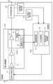
- FIG. 6 is a block diagram showing the configuration of oscillator 1A according to the second embodiment.
- the oscillator 1A further includes a directional coupler 60, an output power detector 61, and a reflected power detector 62 in addition to the configuration of the oscillator 1 according to the first embodiment.
- the directional coupler 60 is provided between the power amplifier 20 and the output terminal 30 and outputs the output power from the final stage device 22 to the antenna 100 . Along with this, directional coupler 60 splits a portion of the output power from power amplifier 20 .
- the output power detector 61 detects the power branched by the directional coupler 60 to detect the magnitude of the output power (microwave) that passes through the directional coupler 60 and is radiated from the antenna 100 .
- the directional coupler 60 receives the reflected wave received by the antenna 100 .
- Directional coupler 60 splits a portion of the reflected power received by antenna 100 .
- the reflected power detector 62 detects the reflected power split by the directional coupler 60 to detect the magnitude of the reflected power received by the antenna 100 and passing through the directional coupler 60 .
- the control unit 90 has the functions of the temperature monitoring unit 41 and the signal generation control unit 91, as in the first embodiment. However, in the second embodiment, the signal generation control unit 91 detects not only the temperature of the final stage device 22 monitored by the temperature monitoring unit 41, but also the output power detected by the output power detection unit 61 and the reflected power detection unit 62. Receive the detected reflected power. The signal generation controller 91 causes the signal generator 10 to perform at least one of frequency control, phase control, and amplitude control of the oscillation signal based on the detected temperature, output power, and reflected power.
- the signal generation control unit 91 causes the signal generation unit 10 to stop generating the oscillation signal.
- Reflectance means the ratio of the reflected power that returns as a reflected wave to the output power that was radiated as an output wave. In other words, reflectance is the ratio of reflected power to output power.
- the signal generation control unit 91 causes the signal generation unit 10 to perform at least frequency control, phase control, and amplitude control of the oscillation signal. let me do one
- the signal generation control unit 91 causes the signal generation unit 10 to perform neither frequency control, phase control, nor amplitude control, but the predetermined frequency. , phase, and amplitude.
- Embodiment 3 will be described below with reference to FIGS. 7 to 9.
- FIG. the description will focus on the differences between the present embodiment and the second embodiment.
- the same reference numerals are assigned to the same components as those of the first and second embodiments, and the description thereof may be omitted.
- FIG. 7 is a block diagram showing the configuration of an oscillator 1B according to the third embodiment.
- FIG. 8 is a schematic diagram showing the arrangement of the final stage device 22, the temperature sensor 40, and the switching section 70 in the oscillator 1B.
- FIG. 9 is a schematic diagram showing an example in which the final stage device 22 and the switching section 70 in the oscillator 1B are provided on the same IC chip.
- the oscillator 1B includes a power amplifier 20A instead of the power amplifier 20, and a controller 90A instead of the controller 90.
- the power amplifier 20 ⁇ /b>A further includes a switching section 70 in addition to the device group 21 , final stage device 22 and temperature sensor 40 .
- the switching unit 70 turns on or off the function of the final stage device 22 . Specifically, the switching unit 70 switches connection and disconnection of the driving power supply to the final stage device 22, for example. Alternatively, the switching unit 70 may connect or disconnect the electric path between the final stage device 22 and the device group 21 or the electric path between the final stage device 22 and the directional coupler 60. .
- the switching unit 70 is, for example, a logic circuit.
- the switching unit 70 is provided in the package 200A including the final stage device 22 and the temperature sensor 40 . In Embodiment 3, the switching unit 70 is provided inside the package 200A (see FIG. 8).
- the control section 90A has the function of the output control section 92 in addition to the functions of the temperature monitoring section 41 and the signal generation control section 91 .
- the output control section 92 controls the switching section 70 based on the temperature (detected temperature) of the final stage device 22, the output power, and the reflected power.
- the output control section 92 causes the switching section 70 to turn off the function of the final stage device 22 . If the detected temperature is less than the first threshold and the reflectance is less than the predetermined value, the output control section 92 causes the switching section 70 to turn on the function of the final stage device 22 .
- the switching unit 70 may be integrated with the final stage device 22 into one chip. That is, the switching section 70 and the final stage device 22 may be provided inside the same IC chip (see FIG. 9).
- each modification of Embodiment 1 is applicable.
- the switching section 70, the final stage device 22, and the temperature sensor 40 are integrated into one chip (see FIG. 9). That is, the switching section 70, the final stage device 22, and the temperature sensor 40 are provided inside the same IC chip.
- the temperature sensor 40 is provided in the central portion of the IC chip, and the switching unit 70 is provided in the end portion of the IC chip.
- the switching unit 70 may be applied to the oscillator 1 according to the first embodiment.
- the output control section 92 controls the switching section 70 based on the temperature (detected temperature) of the final stage device 22 monitored by the temperature monitoring section 41 . For example, if the detected temperature is equal to or higher than the first threshold, the output control section 92 causes the switching section 70 to turn off the function of the final stage device 22 . If the detected temperature is less than the first threshold, the output control section 92 causes the switching section 70 to turn on the function of the final stage device 22 .
- Embodiment 4 will be described below with reference to FIGS. 10 and 11.
- FIG. Here, the description will focus on the differences between the present embodiment and the third embodiment.
- the same reference numerals are given to the same constituent elements as those of Embodiments 1 to 3, and the explanation thereof may be omitted.
- FIG. 10 is a block diagram showing the configuration of an oscillator 1C according to the fourth embodiment.
- FIG. 11 is a diagram showing the relationship between the temperature rise and the reflected power stored in the storage section 81 in the oscillator 1C.
- the oscillator 1C does not include the reflected power detection section 62, but includes a storage section 81. Furthermore, the oscillator 1C includes a control section 90B instead of the control section 90A.
- the control unit 90B further includes the functions of the power estimation unit 80 in addition to the signal generation control unit 91, the output control unit 92, and the temperature monitoring unit 41.
- the storage unit 81 is composed of ROM (read only memory), RAM (random access memory), EEPROM (electrically erasable programmable read only memory), or the like.
- the storage unit 81 includes the output power detected by the output power detection unit 61 as a parameter, and stores relationship information indicating the relationship between the reflected power and the temperature rise of the final stage device 22 .
- the relational information is, for example, a graph G1 shown in FIG. In FIG. 11, the horizontal axis represents temperature rise (° C.) and the vertical axis represents reflected power (W).
- the related information is not limited to graph G1.
- the relational information may be a table corresponding to the graph G1, that is, information including a plurality of sets in which reflected powers and elevated temperatures are associated with each other.
- the relationship information may be an approximate expression representing the graph G1.
- the temperature of the final stage device 22 is affected by the ambient temperature of the oscillator 1 . Therefore, the storage unit 81 may have a plurality of approximation formulas corresponding to the ambient temperature.
- the power estimation unit 80 estimates the reflected power received by the antenna 100 using the temperature of the final stage device 22 detected by the temperature sensor 40 and related information.
- the power estimator 80 calculates an increase in the temperature of the final stage device 22 (increase in temperature) based on the two temperatures of the final stage device 22 continuously detected at predetermined time intervals.
- the power estimator 80 uses the relationship information stored in the storage 81 to obtain (estimate) the value of the reflected power corresponding to the calculated temperature rise.
- the signal generation control section 91 detects the temperature (detected temperature) of the final stage device 22 monitored by the temperature monitoring section 41, the output power detected by the output power detection section 61, and the power estimation section 80. Receive reflected power.
- the signal generation controller 91 causes the signal generator 10 to perform at least one of frequency control, phase control, and amplitude control of the oscillation signal based on the detected temperature, output power, and reflected power.
- the signal generation control unit 91 causes the signal generation unit 10 to stop generating the oscillation signal. .
- the signal generation control unit 91 causes the signal generation unit 10 to perform at least frequency control, phase control, and amplitude control of the oscillation signal. let me do one
- the signal generation control unit 91 causes the signal generation unit 10 to perform neither frequency control, phase control, nor amplitude control, but the predetermined frequency. , phase, and amplitude.
- the output control section 92 controls the switching section 70 based on the detected temperature, the output power, and the reflected power estimated by the power estimation section 80 . For example, if at least one of the detected temperature is equal to or higher than the first threshold and the reflectance is equal to or higher than a predetermined value, the output control section 92 causes the switching section 70 to turn off the function of the final stage device 22 .
- the output control section 92 causes the switching section 70 to turn on the function of the final stage device 22 .
- the degree of coupling changes. Since the oscillator 1C does not have a circulator and a terminator, the output impedance of the directional coupler 60 changes when the load impedance of the antenna changes.
- the detection of the output power and reflected power depends on the degree of coupling of the directional coupler 60. Therefore, when the degree of coupling changes, the detection accuracy of output power and reflected power may decrease.
- the degree of coupling of the directional coupler 60 is almost unchanged by the output of the output wave (microwave). However, reception of reflected waves may change the degree of coupling of the directional coupler 60 . As a result, the accuracy of reflected power detection by the reflected power detection unit 62 may decrease.
- the detected temperature is also used in order to accurately estimate the amount of reflected power, thereby improving the accuracy of reflected power detection. Further, by using the relationship information indicating the relationship between the reflected power and the temperature rise of the final-stage device 22, it is possible to suppress deterioration in the detection accuracy of the reflected power.
- the directional coupler 60 is not an essential component in the fourth embodiment.
- the oscillator 1C may be configured to detect output power and estimate reflected power.
- oscillator 1 of the first embodiment may have output power detector 61, power estimator 80, and storage 81 of the fourth embodiment.
- control unit 90 does not have to include the temperature monitoring unit 41 and the power estimation unit 80 .
- temperature monitoring unit 41 and power estimation unit 80 are provided outside control unit 90 .
- the temperature monitoring unit 41 receives and monitors the temperature detected by the temperature sensor 40 and transmits information about the detected temperature to the control unit 90 .
- Power estimator 80 estimates the reflected power received by antenna 100 using the temperature of final-stage device 22 detected by temperature sensor 40 and related information, and transmits information about the reflected power to controller 90 .
- the oscillator 1A according to Embodiment 2 may have the power estimation section 80 and the storage section 81 according to Embodiment 4 instead of the reflected power detection section 62.
- the oscillator 1B according to the third embodiment may have the output power detection unit 61, the power estimation unit 80 and the storage unit 81 according to the fourth embodiment.
- the reflected power detection section 62 can improve the detection accuracy of the reflected power.
- the oscillators (1; 1A; 1B; 1C) of the first aspect generate output power for providing microwaves that are output waves.
- An oscillator (1; 1A; 1B; 1C) of this aspect includes a signal generator (10), a power amplifier (20), and a temperature sensor (40).
- a signal generator (10) generates an oscillation signal.
- a power amplifier (20) amplifies the oscillating signal to produce output power.
- the power amplifier (20) includes a final stage device (22).
- the final stage device (22) is packaged.
- a temperature sensor (40) is provided in the package (200; 200a; 200b; 200A) containing the final stage device (22).
- the temperature sensor (40) provided inside the package (200; 200a; 200b; 200A) containing the final stage device (22) detects the actual temperature of the final stage device (22) and the temperature sensor.
- the error from the detected temperature of (40) becomes small.
- the delay time from the occurrence of the temperature change of the final stage device (22) to the detection of the temperature change of the final stage device (22) by the temperature sensor (40) is also shortened. That is, the temperature sensor (40) can more accurately detect the temperature of the final stage device (22).
- the final stage device (22) and the temperature sensor (40) are integrated into one chip.
- the temperature of the final stage device (22) can be detected more accurately.
- the oscillator (1A; 1B) of the third mode includes a directional coupler (60), an output power detector (61), and a reflected power detector (62) in addition to the first or second mode. , is further provided.
- a directional coupler (60) is placed between the final stage device (22) and the output terminal (30) of the oscillator (1A; 1B).
- a directional coupler (60) outputs the output power output by the final stage device (22) to an output terminal (30), and converts the reflected power corresponding to the reflected wave returning to the output terminal (30) out of the output waves to receive.
- the output power detector (61) is connected to the directional coupler (60) and detects the output power.
- a reflected power detector (62) is connected to the directional coupler (60) to detect reflected power.
- the oscillators (1B; 1C) of the fourth mode further include an output power detection section (61), a storage section (81), and a power estimation section (80) in addition to the first mode.
- the output power detector (61) detects the output power output by the final stage device (22).
- a storage section (81) stores the reflected power and the final stage device (22) using the temperature of the final stage device (22) detected by the temperature sensor (40) and the output power detected by the output power detection section (61) as parameters. and the relationship information indicating the relationship with the rising temperature.
- a power estimator (80) estimates the value of the reflected power based on the relational information.
- the oscillator (1C) of the fifth aspect further includes a signal generation control section (91) in addition to any one of the first to fourth aspects.
- a signal generation controller (91) controls the signal generator (10).
- the signal generator (10) is operable to perform at least one of frequency control, phase control and amplitude control of the oscillation signal.
- a signal generation control section (91) instructs the signal generation section (10) to generate or stop an oscillation signal or at least one of frequency control, phase control, and amplitude control based on at least the temperature detected by the temperature sensor (40). to do
- the oscillator (1B; 1C) of the sixth aspect further comprises a switching section (70) in addition to any one of the first to fifth aspects.
- a switching unit (70) turns on or off the function of the final stage device (22).
- the switching section (70) is provided in the package (200A).
- the switching section (70), the final stage device (22) and the temperature sensor (40) are integrated into one chip.
- the temperature of the final stage device (22) can be detected more accurately, and the generation of microwaves can be controlled more accurately.
- the oscillator (1C) of the eighth mode further comprises an output control section (92) in addition to the sixth or seventh mode.
- the output control section (92) controls the switching section (70) based at least on the temperature detected by the temperature sensor (40).
- the final stage device (22) is a gallium oxide device.
- the electric device (2) of the tenth aspect includes the oscillator (1; 1A; 1B; 1C) of any one of the first to ninth aspects and the output provided by the oscillator (1; 1A; 1B; 1C) It comprises an antenna (100) for emitting waves and a cavity (3) for containing an object to be heated.
- the electric appliance (2) of this aspect is, for example, a microwave oven (2a).
- the microwave oven (2a) according to this configuration can more accurately detect the temperature of the final-stage device (22).
- the oscillator of the present disclosure can be applied to equipment that uses microwaves, such as dryers, in addition to microwave ovens.
- Reference Signs List 1 1A, 1B, 1C Oscillator 2 Electrical equipment 2a Microwave oven 3 Cavity 10 Signal generator 20, 20A Power amplifier 21 Device group 22 Final stage device 30 Output terminal 40 Temperature sensor 41 Temperature monitoring unit 50a, 50b Electric circuit 60
- Directional coupling device 61 output power detection unit 62 reflected power detection unit 70 switching unit 80 power estimation unit 81 storage unit 90, 90A, 90B control unit 91 signal generation control unit 92 output control unit 100 antenna 200, 200a, 200b, 200A package 201, 202 Terminal 203 Flange
Landscapes
- Engineering & Computer Science (AREA)
- Power Engineering (AREA)
- Physics & Mathematics (AREA)
- Electromagnetism (AREA)
- Microelectronics & Electronic Packaging (AREA)
- Control Of High-Frequency Heating Circuits (AREA)
Priority Applications (4)
| Application Number | Priority Date | Filing Date | Title |
|---|---|---|---|
| CN202380020378.5A CN118661472A (zh) | 2022-02-18 | 2023-01-11 | 振荡器以及电气设备 |
| EP23756039.6A EP4482251A4 (en) | 2022-02-18 | 2023-01-11 | OSCILLATOR AND ELECTRICAL DEVICE |
| US18/727,677 US20250106957A1 (en) | 2022-02-18 | 2023-01-11 | Oscillator and electric device |
| JP2024501017A JPWO2023157511A1 (https=) | 2022-02-18 | 2023-01-11 |
Applications Claiming Priority (2)
| Application Number | Priority Date | Filing Date | Title |
|---|---|---|---|
| JP2022024163 | 2022-02-18 | ||
| JP2022-024163 | 2022-02-18 |
Publications (1)
| Publication Number | Publication Date |
|---|---|
| WO2023157511A1 true WO2023157511A1 (ja) | 2023-08-24 |
Family
ID=87578069
Family Applications (1)
| Application Number | Title | Priority Date | Filing Date |
|---|---|---|---|
| PCT/JP2023/000451 Ceased WO2023157511A1 (ja) | 2022-02-18 | 2023-01-11 | 発振器および電気機器 |
Country Status (5)
| Country | Link |
|---|---|
| US (1) | US20250106957A1 (https=) |
| EP (1) | EP4482251A4 (https=) |
| JP (1) | JPWO2023157511A1 (https=) |
| CN (1) | CN118661472A (https=) |
| WO (1) | WO2023157511A1 (https=) |
Families Citing this family (1)
| Publication number | Priority date | Publication date | Assignee | Title |
|---|---|---|---|---|
| EP4297277B1 (en) * | 2021-02-19 | 2025-04-16 | Panasonic Intellectual Property Management Co., Ltd. | Rf energy radiation device |
Citations (8)
| Publication number | Priority date | Publication date | Assignee | Title |
|---|---|---|---|---|
| JPH0896947A (ja) * | 1994-09-28 | 1996-04-12 | Matsushita Electric Ind Co Ltd | 高周波加熱装置 |
| WO2007074828A1 (ja) * | 2005-12-26 | 2007-07-05 | Autonetworks Technologies, Ltd. | 電力供給制御装置及びその閾値変更方法 |
| JP2009252619A (ja) * | 2008-04-09 | 2009-10-29 | Panasonic Corp | マイクロ波処理装置 |
| JP2015177635A (ja) * | 2014-03-14 | 2015-10-05 | トヨタ自動車株式会社 | 電圧コンバータ |
| JP2018508963A (ja) * | 2015-03-06 | 2018-03-29 | ワールプール コーポレイション | 高周波電力測定システム用の高出力増幅器の較正方法 |
| JP2019032149A (ja) * | 2017-08-09 | 2019-02-28 | イマジニアリング株式会社 | 食品加熱装置 |
| JP2020004720A (ja) * | 2018-06-29 | 2020-01-09 | シャープ株式会社 | 解凍装置および解凍方法 |
| WO2020050356A1 (ja) | 2018-09-07 | 2020-03-12 | パナソニックIpマネジメント株式会社 | Rfエネルギー放射装置 |
Family Cites Families (6)
| Publication number | Priority date | Publication date | Assignee | Title |
|---|---|---|---|---|
| JP3641184B2 (ja) * | 2000-03-28 | 2005-04-20 | 株式会社東芝 | バイポーラトランジスタを用いた高周波電力増幅器 |
| WO2015028839A1 (en) * | 2013-08-29 | 2015-03-05 | Freescale Semiconductor, Inc. | Integrated solid state microwave power generation modules |
| US20190028066A1 (en) * | 2017-07-24 | 2019-01-24 | Macom Technology Solutions Holdings, Inc. | Fet operational temperature determination by field plate resistance thermometry |
| JP2020159949A (ja) * | 2019-03-27 | 2020-10-01 | 東京エレクトロン株式会社 | 高周波供給装置及び高周波電力の供給方法 |
| US10985617B1 (en) * | 2019-12-31 | 2021-04-20 | Energous Corporation | System for wirelessly transmitting energy at a near-field distance without using beam-forming control |
| US11621206B2 (en) * | 2020-08-05 | 2023-04-04 | Nxp Usa, Inc. | Amplifier with integrated temperature sensor |
-
2023
- 2023-01-11 JP JP2024501017A patent/JPWO2023157511A1/ja active Pending
- 2023-01-11 EP EP23756039.6A patent/EP4482251A4/en active Pending
- 2023-01-11 CN CN202380020378.5A patent/CN118661472A/zh active Pending
- 2023-01-11 US US18/727,677 patent/US20250106957A1/en active Pending
- 2023-01-11 WO PCT/JP2023/000451 patent/WO2023157511A1/ja not_active Ceased
Patent Citations (8)
| Publication number | Priority date | Publication date | Assignee | Title |
|---|---|---|---|---|
| JPH0896947A (ja) * | 1994-09-28 | 1996-04-12 | Matsushita Electric Ind Co Ltd | 高周波加熱装置 |
| WO2007074828A1 (ja) * | 2005-12-26 | 2007-07-05 | Autonetworks Technologies, Ltd. | 電力供給制御装置及びその閾値変更方法 |
| JP2009252619A (ja) * | 2008-04-09 | 2009-10-29 | Panasonic Corp | マイクロ波処理装置 |
| JP2015177635A (ja) * | 2014-03-14 | 2015-10-05 | トヨタ自動車株式会社 | 電圧コンバータ |
| JP2018508963A (ja) * | 2015-03-06 | 2018-03-29 | ワールプール コーポレイション | 高周波電力測定システム用の高出力増幅器の較正方法 |
| JP2019032149A (ja) * | 2017-08-09 | 2019-02-28 | イマジニアリング株式会社 | 食品加熱装置 |
| JP2020004720A (ja) * | 2018-06-29 | 2020-01-09 | シャープ株式会社 | 解凍装置および解凍方法 |
| WO2020050356A1 (ja) | 2018-09-07 | 2020-03-12 | パナソニックIpマネジメント株式会社 | Rfエネルギー放射装置 |
Non-Patent Citations (1)
| Title |
|---|
| See also references of EP4482251A4 |
Also Published As
| Publication number | Publication date |
|---|---|
| CN118661472A (zh) | 2024-09-17 |
| EP4482251A4 (en) | 2025-05-07 |
| US20250106957A1 (en) | 2025-03-27 |
| EP4482251A1 (en) | 2024-12-25 |
| JPWO2023157511A1 (https=) | 2023-08-24 |
Similar Documents
| Publication | Publication Date | Title |
|---|---|---|
| JP5167678B2 (ja) | マイクロ波処理装置 | |
| US10785833B2 (en) | Integrated solid state microwave power generation modules | |
| CN101296535A (zh) | 高频发射装置的控制方法 | |
| JP5104048B2 (ja) | マイクロ波処理装置 | |
| JP2008108491A (ja) | マイクロ波処理装置 | |
| JP7788633B2 (ja) | Rfエネルギー放射装置 | |
| US11038473B2 (en) | Phase shifters for gallium nitride amplifiers and related methods | |
| WO2023157511A1 (ja) | 発振器および電気機器 | |
| JP5195255B2 (ja) | マイクロ波加熱装置 | |
| CN111720865B (zh) | 具有再辐射器的rf加热设备 | |
| JP2018142452A (ja) | 高周波加熱装置 | |
| US20120241445A1 (en) | Cooking appliance employing microwaves | |
| JP2010080185A (ja) | マイクロ波加熱装置 | |
| JP5467341B2 (ja) | マイクロ波処理装置 | |
| JP2010073382A (ja) | マイクロ波処理装置 | |
| JP2009252564A (ja) | マイクロ波処理装置 | |
| JP2009252619A (ja) | マイクロ波処理装置 | |
| US20250344297A1 (en) | Signal output device, microwave oven, refrigerator, and freezer | |
| KR101748608B1 (ko) | 마이크로웨이브를 이용한 조리기기 | |
| JP2010192359A (ja) | マイクロ波処理装置 | |
| KR101620438B1 (ko) | 마이크로웨이브를 이용한 조리기기 | |
| KR101748606B1 (ko) | 마이크로웨이브를 이용한 조리기기 | |
| KR101748607B1 (ko) | 마이크로웨이브를 이용한 조리기기 | |
| KR101620447B1 (ko) | 마이크로웨이브를 이용한 조리기기 | |
| CN116830802A (zh) | Rf能量辐射装置 |
Legal Events
| Date | Code | Title | Description |
|---|---|---|---|
| 121 | Ep: the epo has been informed by wipo that ep was designated in this application |
Ref document number: 23756039 Country of ref document: EP Kind code of ref document: A1 |
|
| WWE | Wipo information: entry into national phase |
Ref document number: 2024501017 Country of ref document: JP |
|
| WWE | Wipo information: entry into national phase |
Ref document number: 18727677 Country of ref document: US |
|
| WWE | Wipo information: entry into national phase |
Ref document number: 202380020378.5 Country of ref document: CN |
|
| WWE | Wipo information: entry into national phase |
Ref document number: 2023756039 Country of ref document: EP |
|
| NENP | Non-entry into the national phase |
Ref country code: DE |
|
| ENP | Entry into the national phase |
Ref document number: 2023756039 Country of ref document: EP Effective date: 20240918 |
|
| WWP | Wipo information: published in national office |
Ref document number: 18727677 Country of ref document: US |