WO2023153309A1 - 冷媒分配器、熱交換器及び冷凍サイクル装置 - Google Patents
冷媒分配器、熱交換器及び冷凍サイクル装置 Download PDFInfo
- Publication number
- WO2023153309A1 WO2023153309A1 PCT/JP2023/003414 JP2023003414W WO2023153309A1 WO 2023153309 A1 WO2023153309 A1 WO 2023153309A1 JP 2023003414 W JP2023003414 W JP 2023003414W WO 2023153309 A1 WO2023153309 A1 WO 2023153309A1
- Authority
- WO
- WIPO (PCT)
- Prior art keywords
- refrigerant
- mixing section
- liquid
- phase
- mixing
- Prior art date
- Legal status (The legal status is an assumption and is not a legal conclusion. Google has not performed a legal analysis and makes no representation as to the accuracy of the status listed.)
- Ceased
Links
Images


Classifications
-
- F—MECHANICAL ENGINEERING; LIGHTING; HEATING; WEAPONS; BLASTING
- F25—REFRIGERATION OR COOLING; COMBINED HEATING AND REFRIGERATION SYSTEMS; HEAT PUMP SYSTEMS; MANUFACTURE OR STORAGE OF ICE; LIQUEFACTION SOLIDIFICATION OF GASES
- F25B—REFRIGERATION MACHINES, PLANTS OR SYSTEMS; COMBINED HEATING AND REFRIGERATION SYSTEMS; HEAT PUMP SYSTEMS
- F25B39/00—Evaporators; Condensers
- F25B39/02—Evaporators
- F25B39/028—Evaporators having distributing means
-
- F—MECHANICAL ENGINEERING; LIGHTING; HEATING; WEAPONS; BLASTING
- F25—REFRIGERATION OR COOLING; COMBINED HEATING AND REFRIGERATION SYSTEMS; HEAT PUMP SYSTEMS; MANUFACTURE OR STORAGE OF ICE; LIQUEFACTION SOLIDIFICATION OF GASES
- F25B—REFRIGERATION MACHINES, PLANTS OR SYSTEMS; COMBINED HEATING AND REFRIGERATION SYSTEMS; HEAT PUMP SYSTEMS
- F25B41/00—Fluid-circulation arrangements
- F25B41/40—Fluid line arrangements
- F25B41/42—Arrangements for diverging or converging flows, e.g. branch lines or junctions
Definitions
- the present disclosure relates to refrigerant distributors, heat exchangers, and refrigeration cycle devices.
- An air conditioner is equipped with a refrigerant circuit that circulates refrigerant.
- the refrigerant circuit includes a compressor that compresses the refrigerant, an expansion device that expands the refrigerant, an indoor heat exchanger that causes the refrigerant to exchange heat with indoor air, and an outdoor heat exchanger that causes the refrigerant to exchange heat with outdoor air. and a refrigerant pipe connecting them annularly.
- the indoor heat exchanger absorbs heat from the outside and functions as an evaporator that evaporates the refrigerant
- the outdoor heat exchange function as an evaporator.
- Refrigerant circulating in the refrigerant circuit is sent out in a gas-liquid two-phase state from the expansion device, flows into the evaporator, that is, the indoor heat exchanger or the outdoor heat exchanger, and flows through the heat transfer tubes built into the evaporator to be mixed with air. exchange heat.
- the gas-liquid two-phase refrigerant exchanges heat with the air
- the liquid-phase refrigerant contained in this refrigerant evaporates and changes into a gas-phase refrigerant.
- the refrigerant changes from a gas-liquid two-phase state to a gas-phase single-phase state while flowing through the heat transfer tubes. That is, the refrigerant flows in a gas-liquid two-phase state through some sections of the heat transfer tubes, and flows in a single gas-phase state through the remaining sections of the heat transfer tubes.
- the indoor heat exchanger and the outdoor heat exchanger that function as evaporators are provided with a plurality of heat transfer tubes and a refrigerant distributor that distributes the refrigerant to these heat transfer tubes, and distributes the refrigerant to each heat transfer tube.
- the flow rate of the refrigerant inside each heat transfer tube is reduced, and the pressure loss of the refrigerant is reduced.
- the refrigerant pipe inside the evaporator has a curved portion located upstream from the refrigerant distributor, centrifugal force is applied to the gas-liquid two-phase refrigerant when it passes through the curved portion, and the refrigerant is contained.
- the liquid-phase refrigerant flows into the refrigerant distributor in a biased state.
- the amount of liquid-phase refrigerant distributed to each heat transfer tube by the refrigerant distributor varies.
- a heat transfer tube with a smaller amount of distributed liquid-phase refrigerant has a longer section in which the refrigerant flows in a gas-phase single-phase state.
- the heat exchange efficiency in the section where the refrigerant flows in the heat transfer tube in the gas-phase single-phase state is , the heat exchange efficiency in the section where the refrigerant flows in the gas-liquid two-phase state is extremely low. For this reason, the heat exchange efficiency is lower in a heat transfer tube having a longer section in which the refrigerant flows in a single gas phase state. Therefore, if the length of the section in which the refrigerant flows in each heat transfer tube in a single gas phase state varies, the heat exchange efficiency of the evaporator will decrease.
- the refrigerant distributor described in Patent Document 1 has an inlet pipe into which a gas-liquid two-phase refrigerant flows, and the gas-liquid two-phase refrigerant flowing from the inlet pipe is mixed and branched. a branch space, a plurality of outlet pipes for flowing out the gas-liquid two-phase refrigerant branched in the branch space, an inflow passage connecting the inlet pipe and the branch space, and a branch space and the plurality of outlet pipes, respectively. and a plurality of connecting outflow passages.
- the branch space has a recessed mixing portion formed at a position facing the inflow passage.
- the inner diameter of the inflow passage is Da [mm]
- the cross-sectional area of the inflow passage is Ai [mm 2 ]
- the inner diameter of the mixing section is Db [mm]
- the area of the branch space is Av [mm 2 ]
- the height of the branch space. is Hv [mm]
- the area of the circumscribed circle of the outflow passage is Apo [mm 2 ]
- the area of the inscribed circle of the outflow passage is Api [mm2] then Ai/( ⁇ Da ⁇ Hv) ⁇ 0.5, Av/(Apo ⁇ Api) ⁇ 2.0, Db/Da ⁇ 1.0.
- the refrigerant distributor described in Patent Document 1 may not be able to reduce variations in the amount of refrigerant distributed to each heat transfer tube, depending on the flow rate, type, and temperature of the refrigerant flowing into the refrigerant distributor. be.
- the present disclosure has been made in view of the above circumstances, and when distributing refrigerant to a plurality of heat transfer tubes, the amount of refrigerant distributed to each heat transfer tube is determined regardless of the flow rate, type, and temperature of the refrigerant.
- the purpose is to reduce variability.
- the refrigerant distributor includes a mixing section having a cylindrical shape.
- a first end of the mixing section is formed with an inlet through which a refrigerant flows.
- a plurality of outlets through which the refrigerant flows are formed at a second end opposite to the first end of the mixing section.
- a recess is formed in the second end of the mixing section facing the inlet.
- the mixing section guides the refrigerant that has flowed in from the inlet to flow along the first end of the mixing section and the side wall of the mixing section, diffuses it in the circumferential direction of the second end, and then sends it out from the outlet. do.
- Refrigerant circuit diagram of air conditioner according to Embodiment 1 of the present disclosure Mollier diagram showing the state of refrigerant circulating in the refrigerant circuit according to Embodiment 1 of the present disclosure
- a diagram showing configurations of an indoor heat exchanger and an outdoor heat exchanger according to Embodiment 1 of the present disclosure (A) Perspective view of refrigerant distributor and internal refrigerant piping according to Embodiment 1 of the present disclosure, (B) Cross-sectional view of internal refrigerant piping according to Embodiment 1 of the present disclosure (A) Perspective view of the refrigerant distributor according to Embodiment 1 of the present disclosure, (B) Plan view of the refrigerant distributor according to Embodiment 1 of the present disclosure Cross-sectional view taken along line VI-VI in FIG.
- FIG. 5(B) of the refrigerant distributor according to the first embodiment of the present disclosure A diagram showing the relationship between the height of the mixing section and the liquid-phase refrigerant distribution ratio of the reference outlet pipe according to Embodiment 1 of the present disclosure Schematic diagram showing an example of the flow of refrigerant inside the refrigerant distributor according to Embodiment 1 of the present disclosure (A) Schematic diagram showing an example of the flow of refrigerant inside the refrigerant distributor according to Embodiment 1 of the present disclosure when the liquid-phase refrigerant distribution ratio of the reference outlet pipe is suppressed, (B) Mixing section (C ) Schematic showing an example of the flow of refrigerant inside the refrigerant distributor according to Embodiment 1 of the present disclosure when the liquid-phase refrigerant distribution ratio of the reference outlet pipe is not suppressed due to the height of the mixing section being too large.
- FIG. 1 A diagram showing the relationship between the refrigerant mass flow rate and the liquid-phase refrigerant distribution ratio of the reference outlet pipe according to the first embodiment of the present disclosure.
- a diagram showing the relationship between the height of the mixing section and the liquid-phase refrigerant distribution ratio of the reference outlet pipe according to Embodiment 1 of the present disclosure A diagram showing the relationship between the height of the mixing section and the pressure loss of the refrigerant according to Embodiment 2 of the present disclosure
- A) A plan view of a refrigerant distributor according to Embodiment 3 of the present disclosure
- Schematic diagram showing an example of a refrigerant flow inside a refrigerant distributor according to Embodiment 3 of the present disclosure Vertical cross-sectional view of a refrigerant distributor according to
- An air conditioner 100 shown in FIG. 1 conditions the air inside a space to be air-conditioned, such as an indoor space or an interior space of an automobile.
- Air conditioner 100 is an example of a refrigeration cycle device.
- the air conditioner 100 includes a refrigerant circuit 10 that circulates refrigerant and a control device 20 that controls the operation of the refrigerant circuit 10 .
- the refrigerant circuit 10 includes a compressor 1 that compresses the refrigerant, an expansion device 2 that expands the refrigerant and switches the circulation direction of the refrigerant inside the refrigerant circuit 10, and an indoor unit 6 that is installed inside the air-conditioned space.
- An indoor heat exchanger 3 that causes the refrigerant to exchange heat with the air inside the air-conditioned space, and an outdoor unit 7 installed outside the air-conditioned space, and the refrigerant exchanges heat with the air outside the air-conditioned space.
- the indoor heat exchanger 3 and the outdoor heat exchanger 4 are examples of heat exchangers.
- the control device 20 includes a processor that executes various processes and a memory that stores data and programs.
- the processor of the control device 20 functions as an operation control section that controls the operation of the refrigerant circuit 10 by executing a program stored in the memory, and transmits control signals to control the compressor 1, the expansion device 2, the indoor It controls the operation of the unit 6 and the outdoor unit 7.
- the expansion device 2 includes an expansion valve that expands the refrigerant and a four-way valve that switches the circulation direction of the refrigerant.
- the control device 20 controls the four-way valve of the throttle device 2 to switch the circulation direction of the refrigerant, thereby switching the operating state of the air conditioner 100 between the cooling operation state and the heating operation state.
- the four-way valve circulates the refrigerant in the direction indicated by the arrow JJ in FIG.
- the indoor heat exchanger 3 functions as an evaporator that absorbs heat from the outside and evaporates the refrigerant
- the outdoor heat exchanger 4 releases heat to the outside and functions as a condenser that condenses the refrigerant.
- the air inside the air-conditioned space is cooled.
- the four-way valve circulates the refrigerant in the direction indicated by the arrow KK in FIG.
- the indoor heat exchanger 3 functions as a condenser
- the outdoor heat exchanger 4 functions as an evaporator to heat the air inside the air-conditioned space.
- FIG. 2 is a Mollier diagram showing the state of the refrigerant circulating in the refrigerant circuit 10.
- the horizontal axis indicates the enthalpy of the refrigerant
- the vertical axis indicates the pressure of the refrigerant.
- FIG. 2 shows a saturated liquid line MM and a saturated vapor line NN.
- the region in which the enthalpy H of the refrigerant is smaller than the saturated liquid line MM is a region in which the refrigerant is in a single liquid phase state
- the region in which the enthalpy H of the refrigerant is greater than the saturated vapor line NN is a region in which the refrigerant is in a single gas phase state.
- the region where the enthalpy H of the refrigerant is above the saturated liquid line MM and below the saturated vapor line NN is a region where the refrigerant is in a gas-liquid two-phase state.
- the refrigerant is first compressed by the compressor 1, and as shown in the route from point S to point T in FIG. Flow into 4.
- the refrigerant that has flowed into the outdoor heat exchanger 4 exchanges heat with the air outside the air-conditioned space, radiates heat, and is condensed.
- the refrigerant is decompressed by being expanded by the expansion valve provided in the expansion device 2, and becomes a low-pressure gas-liquid two-phase refrigerant as shown in the path from point U to point V in FIG. It flows into exchanger 3 .
- the refrigerant that has flowed into the indoor heat exchanger 3 exchanges heat with the air inside the air-conditioned space, absorbs heat, evaporates, and becomes a low-pressure gas phase as shown in the route from point V to point S in FIG. It becomes refrigerant and flows into the compressor 1 .
- the indoor unit 6 includes a housing that incorporates the indoor heat exchanger 3 , a fan that causes air to flow through the indoor heat exchanger 3 , and a motor that drives the fan under the control of the control device 20 .
- the fan is rotationally driven by a motor and causes the air inside the air-conditioned space to flow into the housing.
- the indoor heat exchanger 3 causes the refrigerant to exchange heat with the air that has flowed into the housing.
- the fan is rotationally driven by a motor, and sends out the air after heat exchange with the refrigerant to the inside of the air-conditioned space. As a result, the air inside the air-conditioned space is conditioned.
- the outdoor unit 7 includes a housing that incorporates the outdoor heat exchanger 4, a fan that causes air to flow through the outdoor heat exchanger 4, and a motor that drives the fan under the control of the control device 20.
- the fan is rotationally driven by a motor and causes air outside the air-conditioned space to flow into the housing.
- the outdoor heat exchanger 4 causes the refrigerant to exchange heat with the air that has flowed into the interior of the housing.
- the fan is rotationally driven by a motor and sends out the air after heat exchange with the refrigerant to the outside of the air-conditioned space.
- the indoor heat exchanger 3 has the same configuration as the outdoor heat exchanger 4.
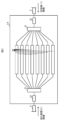
- the indoor heat exchanger 3 and the outdoor heat exchanger 4 are, as shown in FIG.
- a distributor 31 and a pair of internal refrigerant pipes 32 connecting each refrigerant distributor 31 and the main refrigerant pipe 5 are provided.
- the refrigerant distributor 31 is arranged at the inlets of the indoor heat exchanger 3 and the outdoor heat exchanger 4 .
- one of the pair of refrigerant distributors 31 is connected to the compressor 1 via the main refrigerant pipe 5 and the internal refrigerant pipe 32, and the other is connected via the main refrigerant pipe 5 and the internal refrigerant pipe 32. is connected to the diaphragm device 2.
- Refrigerant sent from the compressor 1 or the expansion device 2 flows through the main refrigerant pipe 5 and the internal refrigerant pipe 32 into the refrigerant distributor 31 and is distributed to the heat transfer tubes 30 by the refrigerant distributor 31 .
- Each heat transfer tube 30 is connected to a plurality of heat radiating fins, and the refrigerant distributed to each heat transfer tube 30 by the refrigerant distributor 31 exchanges heat with the air through the heat radiating fins while flowing through each heat transfer tube 30. do.
- the gas-liquid two-phase refrigerant sent from the expansion device 2 flows into the refrigerant distributor 31 connected to the expansion device 2,
- the refrigerant is distributed to each heat transfer tube 30 by the refrigerant distributor 31 and exchanges heat with the air while flowing through each heat transfer tube 30 .
- the flow rate of the refrigerant flowing through each heat transfer tube 30 is reduced, the pressure loss of the refrigerant is reduced, and the indoor heat exchanger 3 and the outdoor heat exchanger which are evaporators 4 improves the heat exchange efficiency.
- the liquid-phase refrigerant contained in this refrigerant evaporates and changes into a gas-phase refrigerant.
- the refrigerant changes from a gas-liquid two-phase state to a gas-phase single-phase state with an extremely low heat transfer coefficient while flowing through the heat transfer tubes.
- the refrigerant flowing through each heat transfer tube 30 changes to a gas-phase single-phase state, joins at a refrigerant distributor 31 connected to the compressor 1 , and is sent from the refrigerant distributor 31 to the compressor 1 .
- the heat exchange efficiency of the evaporator can be improved by reducing the variation in the length of the section where the refrigerant in each heat transfer tube 30 flows in a single gas phase state, that is, the section with low heat exchange efficiency. Variation in the length of the section in which the refrigerant flows in a gas-phase single-phase state can be reduced by reducing variation in the heat load of the refrigerant in each heat transfer tube 30 .
- the heat load of the refrigerant in the heat transfer tube 30 is equal to the product of the mass flow rate of the refrigerant flowing through the heat transfer tube 30 and the difference between the enthalpy of the refrigerant at the inlet of the heat transfer tube 30 and the enthalpy of the refrigerant at the outlet.
- the variation in the heat load of the refrigerant in each heat transfer tube 30 can be reduced by reducing the variation in the mass flow rate of the refrigerant flowing through each heat transfer tube 30 .
- the refrigerant distributor 31 according to the present embodiment reduces the variation in the mass flow rate of the refrigerant flowing through each heat transfer tube 30, thereby reducing the variation in the heat load of the refrigerant in each heat transfer tube 30.
- the heat exchange efficiency of the evaporator is improved by reducing the variation in the length of the section where the refrigerant flows in a gas phase single phase state.
- FIG. 4A is a perspective view of the internal refrigerant pipe 32 connected to the expansion device 2 via the main refrigerant pipe 5 and the refrigerant distributor 31 connected to the internal refrigerant pipe 32.
- the internal refrigerant pipe 32 is connected to the main refrigerant pipe 5, has a linear connection portion 39, is located downstream of the connection portion 39, has a U-shaped curved portion 40, and is located downstream of the curved portion 40. , and a straight pipe portion 41 having a straight shape. A downstream end of the straight pipe portion 41 is connected to the refrigerant distributor 31 .
- FIG. 4B is a cross-sectional view of the internal refrigerant pipe 32 obtained by cutting the internal refrigerant pipe 32 along a cut plane perpendicular to the extending direction of the connecting portion 39 and the straight pipe portion 41 .
- an XYZ orthogonal coordinate system shown in FIGS. 4(A) and 4(B) is set.
- the Z-axis is set parallel to the gravitational direction g.
- the X-axis is set perpendicular to the Z-axis and parallel to a straight line TL passing through the axis 39 a of the connecting portion 39 and the axis 41 a of the straight tube portion 41 .
- the Y-axis is set perpendicular to the X-axis and the Z-axis.
- the gas-phase refrigerant contained in this refrigerant flows through the center of the internal refrigerant pipe 32, and the liquid-phase refrigerant contained in this refrigerant It flows along the inner wall of the internal refrigerant pipe 32 in a film state.
- the density of the gas phase refrigerant and the density of the liquid phase refrigerant there is a difference between the flow velocity of the gas phase refrigerant and the flow velocity of the liquid phase refrigerant.
- the straight tube portion 41 When the refrigerant is flowing through the straight pipe portion 41, a secondary flow is generated to uniform the thickness of the liquid film of the liquid-phase refrigerant adhering to the inner wall, and the unevenness of the liquid-phase refrigerant is reduced. If the straight tube portion 41 is sufficiently long, the unevenness of the liquid phase refrigerant is eliminated while the refrigerant flows through the straight tube portion 41, and the refrigerant flows into the refrigerant distributor 31 in a state in which the liquid phase refrigerant is not unevenly distributed. . However, in the present embodiment, due to structural restrictions, the length of the straight pipe portion 41 is shorter than the length required to eliminate the uneven distribution of the liquid-phase refrigerant. Therefore, the refrigerant flows into the refrigerant distributor 31 in a state in which the liquid-phase refrigerant is biased in the +X-axis direction.
- the refrigerant distributor 31 includes an inlet pipe 50 connected to the internal refrigerant pipe 32, a mixing section 51 connected to the inlet pipe 50, and a plurality of pipes connected to the mixing section 51. It comprises an outlet tube 52 and a recess 53 connected to the mixing section 51 .
- the upstream end of the inlet pipe 50 is connected to the straight pipe portion 41 of the internal refrigerant pipe 32, and the downstream end of the inlet pipe 50 is an inlet formed in the upstream end 51a of the mixing portion 51. 510. That is, the internal refrigerant pipe 32 is connected to the inlet 510 via the inlet pipe 50 .
- the upstream end 51a of the mixing section 51 is an example of a first end.
- the inner diameter of the inlet pipe 50 is equal to the inner diameter of the inlet 510 and the inner diameter of the straight pipe portion 41 of the internal refrigerant pipe 32 .
- the gas-liquid two-phase refrigerant sent out from the expansion device 2 flows into the inlet pipe 50 via the main refrigerant pipe 5 and the internal refrigerant pipe 32 .
- the refrigerant that has flowed into the inlet pipe 50 from the internal refrigerant pipe 32 flows from the inlet pipe 50 into the mixing section 51 via the inlet 510 .
- the mixing section 51 is hollow and has a cylindrical shape.
- An outlet pipe 52 and a hollow portion 53 are connected to the downstream end portion 51 b of the mixing portion 51 .
- the downstream end 51b of the mixing section 51 is an end opposite to the upstream end 51a and is an example of a second end.
- the refrigerant distributor 31 has eight outlet pipes 52, which are the same number as the heat transfer pipes 30, and these outlet pipes 52 are connected to the eight heat transfer pipes 30 described above.
- Each outlet pipe 52 is connected to a different heat transfer pipe 30 .
- the downstream end of each outlet pipe 52 is connected to the heat transfer pipe 30 .
- the upstream end of each outlet pipe 52 is connected to one of a plurality of outlets 511 formed in the downstream end 51 b of the mixing section 51 .
- each heat transfer tube 30 is connected to each outlet 511 via each outlet tube 52 .
- the refrigerant that has flowed into the mixing section 51 from the inlet pipe 50 is delivered from the mixing section 51 to the outlet pipes 52 through the outlets 511 . That is, the refrigerant that has flowed into the mixing section 51 is distributed to each outlet pipe 52 .
- the refrigerant that has flowed into each outlet pipe 52 from the mixing section 51 is delivered from each outlet pipe 52 to the heat transfer tubes 30 connected to each outlet pipe 52 .
- the gas-liquid two-phase refrigerant that has flowed into the refrigerant distributor 31 is distributed to the heat transfer tubes 30 .
- the space inside the hollow portion 53 corresponds to the hollow formed in the mixing portion 51 .
- the depression 53 communicates with the mixing section 51 through a circular opening 51 c formed in the downstream end 51 b of the mixing section 51 and facing the inlet pipe 50 and the inlet 510 . That is, the internal space of the hollow portion 53 , which is a hollow portion of the mixing portion 51 , is formed at the downstream end portion 51 b of the mixing portion 51 so as to face the inlet pipe 50 and the inlet port 510 .
- the hollow portion 53 has a shape in which a hollow cone is connected to a cylinder connected to the opening portion 51c of the mixing portion 51 . A part of the refrigerant sent out from the inlet 510 flows into the internal space of the hollow portion 53 and then flows into the mixing portion 51 from the hollow portion 53 .
- the gas-liquid two-phase refrigerant flows into the refrigerant distributor 31 in a state in which the liquid-phase refrigerant contained in this refrigerant is biased in the +X-axis direction. Therefore, if no measures are taken, the amount of liquid-phase refrigerant sent out from each outlet 511 of the refrigerant distributor 31 through each outlet pipe 52 will vary. Specifically, as shown in FIG. 5B, each outlet tube 52 has a different position in the X-axis direction. The amount of liquid-phase refrigerant to be consumed is increased.
- the outlet pipe 52 with the largest X-coordinate which is the outlet pipe 52 with the largest amount of liquid-phase refrigerant sent out without any measures, is referred to as the “reference outlet pipe 52a”, and other outlet pipes 52 are referred to as “reference outlet pipes 52a”. distinguish. However, when there is no need to distinguish between the reference outlet tube 52a and the other outlet tubes 52, they are collectively referred to simply as "the outlet tube 52".
- the inner diameter of the inlet 510 shown in FIG. Assuming that the gas phase density of this refrigerant is ⁇ g [kg/m 3 ] and the liquid phase density of this refrigerant is ⁇ l [kg/m 3 ], the height h [mm] of the mixing section 51 is given by the following equation 1 meets FIG. 6 is a cross-sectional view of the refrigerant distributor 31 taken along the line VI-VI shown in FIG. 5(B).
- the height h of the mixing section 51 is the distance between the upstream end 51 a and the downstream end 51 b of the mixing section 51 in the internal space of the mixing section 51 .
- the gas-phase density ⁇ g of the refrigerant in the gas-liquid two-phase state is the density of the gas-phase refrigerant contained in this refrigerant
- the liquid-phase density ⁇ l of this refrigerant is the density of the liquid-phase refrigerant contained in this refrigerant.
- the height h of the mixing portion 51 is 2.5 [mm] or more and 4 [mm] or less.
- the diameter Dc [mm] of the depression formed in the mixing section 51 that is the space inside the depression 53 is larger than the inner diameter Di of the inlet 510 .
- the diameter Dc of the depression formed in the mixing portion 51 is equal to the diameter of the opening 51c formed in the mixing portion 51 to which the depression 53 is connected.
- the first distance Li [mm] which is the distance between the depression formed in the mixing portion 51 and the axis QQ of the outflow port 511, is the distance between the axis QQ of the outflow port 511 and the mixing portion. It is larger than the second distance Lo [mm] which is the distance between the side wall 51d of 51 and the second distance Lo [mm].
- the axial center QQ of each outflow port 511 is the same as the axial center of the outlet pipe 52 connected to each outflow port 511 .
- the downstream end 51b of the mixing section 51 is circular, and each outflow port 511 and each outlet pipe 52 extends from the recess 53 to the mixing section 51.
- the eight outlet pipes 52 and the outflow ports 511 to which the outlet pipes 52 are connected are arranged on the circumference of a circle centered on the axis of the recess 53 .
- the axis of the mixing portion 51 is the same as the axis of the recess. Therefore, the distance between the axis QQ of each outlet 511 and the recess is the same, and the distance between the axis QQ of each outlet 511 and the side wall 51d of the mixing section 51 is the same. That is, the first distance Li and the second distance Lo of each outlet 511 are the same.
- the material of the refrigerant distributor 31 is a metal material such as copper or aluminum
- the depression of the mixing portion 51 is formed by cutting the metal material with a drill. At this time, the shorter the distance between the outflow port 511 and the recess of the mixing section 51, the less the amount of the metal material existing between the outflow port 511 and the recess of the mixing section 51, and the more difficult the processing becomes. Manufacturing costs increase.
- the distance between the outflow port 511 and the recess of the mixing section 51 is sufficiently large, which facilitates processing and suppresses the manufacturing cost.
- the material of the refrigerant distributor 31 is not limited to a metal material, and may be an arbitrary material such as resin.
- the method of manufacturing the refrigerant distributor 31 is not limited to the method described above, and may be any method such as press molding or integral molding.
- the distribution of the refrigerant by the refrigerant distributor 31 will be described below using the results of a simulation of the refrigerant flow inside the refrigerant distributor 31, which was performed using a computer.
- the gas-liquid two-phase refrigerant flows into the inlet pipe 50 in a state in which the liquid-phase refrigerant contained in the refrigerant is biased in the +X-axis direction.
- the diameter Dc of the recess of the mixing section 51 7 [mm]
- the inner diameter Di of the inlet 510 6 [mm]
- the first distance Li 8.5 [mm]
- the second distance Lo 2.5. [mm].
- R290, propane was used as the refrigerant unless otherwise stated.
- the temperature of the coolant in the simulation is 10[°C].
- FIG. 7 shows the results obtained by simulation when the mass flow rate G of the refrigerant flowing into the inlet pipe 50 is 50 [kg/h], 100 [kg/h], 150 [kg/h] or 200 [kg/h]. It shows the relationship between the height h of the mixing section 51 and the liquid-phase refrigerant distribution ratio of the reference outlet pipe 52a in a certain case.
- the liquid-phase refrigerant distribution ratio of the reference outlet pipe 52a is the sum of the mass flow rates of the liquid-phase refrigerant delivered from each outlet pipe 511 via each outlet pipe 52, and the ratio from the outlet port 511 to which the reference outlet pipe 52a is connected to the reference outlet. It is the mass flow rate of the liquid refrigerant delivered through pipe 52a.
- liquid-phase refrigerant distribution ratio of the reference outlet pipe 52a which is the largest amount of liquid-phase refrigerant sent out without any countermeasure among the eight outlet pipes 52, becomes small, the liquid-phase refrigerant is unevenly distributed from the reference outlet pipe 52a.
- the liquid-phase refrigerant distribution ratio of the other outlet pipes 52 spaced apart in the ⁇ X-axis direction opposite to the direction is increased, and the variation in the amount of refrigerant delivered from each outlet port 511 is reduced.
- the polygonal line showing the relationship between the height h of the mixing section 51 and the liquid-phase refrigerant distribution ratio of the reference outlet pipe 52a has a downward convex shape regardless of the value of the mass flow rate G of the refrigerant.
- the liquid-phase refrigerant distribution ratio of the reference outlet pipe 52a can be reduced, and the variation in the amount of refrigerant sent out from each outlet 511 can be reduced. can be done.
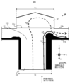
- FIG. 8 shows the flow of the refrigerant inside the refrigerant distributor 31 when the refrigerant in the gas-liquid two-phase state flows into the refrigerant distributor 31 in a state in which the liquid-phase refrigerant CC contained in the refrigerant is biased in the +X-axis direction. shows an example.
- FIG. 8 shows a vertical cross-section of the refrigerant distributor 31 taken along a cutting plane that includes the axial center of the inlet pipe 50 and is perpendicular to the Y-axis direction.
- the arrow AA indicates the flow of the liquid-phase refrigerant CC contained in the refrigerant
- the arrow BB indicates the flow of the gas-phase refrigerant contained in the refrigerant.
- the gas-phase refrigerant flows through the center of the inlet pipe 50 , is sent out from the inlet 510 , flows into the recessed portion 53 , collides with the inner wall of the recessed portion 53 , and flows into the mixing portion 51 . It diffuses in the circumferential direction of the opening 51c. After that, the gas-phase refrigerant flows along the inner wall of the recessed portion 53 and flows into the mixing portion 51 .
- the vapor refrigerant flowing into the mixing section 51 collides with the liquid refrigerant CC flowing along the inner wall of the inlet pipe 50 in a liquid film state and flowing into the mixing section 51 from the inlet 510 inside the mixing section 51 . After colliding with the liquid-phase refrigerant CC, the vapor-phase refrigerant flows along the downstream end 51 b of the mixing section 51 toward the side wall 51 d of the mixing section 51 .
- FIG. 9A shows an example of the refrigerant flow inside the refrigerant distributor 31 when the liquid-phase refrigerant distribution ratio of the reference outlet pipe 52a is suppressed.
- the gas-phase refrigerant collides with the liquid-phase refrigerant CC inside the mixing section 51 , thereby pressing the liquid-phase refrigerant CC against the upstream end 51 a of the mixing section 51 .
- the pressed liquid-phase refrigerant CC flows along the upstream end 51a, reaches the side wall 51d of the mixing section 51, flows along the side wall 51d, and flows downstream of the mixing section 51, as indicated by the arrow AA. It reaches end 51b and is delivered from outlet 511 to reference outlet tube 52a.
- the liquid-phase refrigerant CC diffuses in the circumferential direction of the downstream end 51 b of the mixing section 51 while flowing along the upstream end 51 a and the side wall 51 d of the mixing section 51 .
- FIG. 9B shows an example of the refrigerant flow inside the refrigerant distributor 31 when the liquid-phase refrigerant distribution ratio of the reference outlet pipe 52a is not suppressed because the height h of the mixing portion 51 is too small. ing.
- the proportion of the space inside the mixing section 51 occupied by the liquid-phase refrigerant CC is higher than in the example of FIG. 9(A). Therefore, in the example of FIG. 9B, the flow rate of the gas-phase refrigerant flowing toward the side wall 51d of the mixing portion 51 after colliding with the liquid-phase refrigerant CC inside the mixing portion 51 is the same as in the example of FIG.
- FIG. 9C shows an example of the refrigerant flow inside the refrigerant distributor 31 when the liquid-phase refrigerant distribution ratio of the reference outlet pipe 52a is not suppressed because the height h of the mixing portion 51 is too large. ing.
- the amount of gas-phase refrigerant that flows toward the side wall 51d of the mixing portion 51 without flowing into the recessed portion 53 after flowing in from the inlet 510 is the same as in the example of FIG. a lot compared. Therefore, the force that presses the liquid-phase refrigerant CC against the upstream end portion 51a of the mixing section 51, which is applied from the gas-phase refrigerant to the liquid-phase refrigerant CC, is smaller than in the example of FIG.
- the liquid-phase refrigerant CC is suppressed from directly flowing into the reference outlet pipe 52a, the liquid-phase refrigerant distribution ratio of the reference outlet pipe 52a is suppressed, and each outlet Variation in the amount of liquid-phase refrigerant CC delivered from 511 is suppressed.
- the height h of the mixing portion 51 is such that the liquid-phase refrigerant CC directly flows into the reference outlet pipe 52a, not only when centrifugal force is applied to the refrigerant at the curved portion 40 of the internal refrigerant pipe 32, but also when the refrigerant Also when gravity acts in a direction that is not parallel to the flow direction of the refrigerant, the amount of liquid-phase refrigerant CC delivered from each outlet 511 varies. Specifically, when the axis of the inlet pipe 50 is tilted with respect to the direction of gravity g, gravity is applied to the refrigerant flowing inside the inlet pipe 50 in a direction not parallel to the flow direction of the refrigerant. The liquid phase refrigerant CC contained in is biased.
- the diameter Dc of the recess of mixing portion 51 is configured to be larger than the inner diameter Di of inlet 510 .
- the gas-phase refrigerant that has flowed into the mixing portion 51 from the recessed portion 53 has a large contact area with the liquid-phase refrigerant CC that has flowed into the mixing portion 51 from the inlet 510, and the gas-phase refrigerant is the liquid-phase refrigerant.
- the force that presses the CC against the upstream end 51a of the mixing section 51 is large.
- FIG. 10 shows the distance from the internal refrigerant pipe 32 to the inlet pipe 50 when the height h of the mixing section 51 is 2 [mm], 3 [mm], 4 [mm] or 5 [mm], which is obtained by simulation. and the liquid-phase refrigerant distribution ratio of the reference outlet pipe 52a.
- the larger the mass flow rate G of the refrigerant the smaller the liquid-phase refrigerant distribution ratio of the reference outlet pipe 52a.
- the greater the mass flow rate G of the refrigerant the greater the difference between the velocity of the gas-phase refrigerant contained in the refrigerant and the velocity of the liquid-phase refrigerant CC. big.
- the difference between the dynamic pressure of the gas-phase refrigerant and the dynamic pressure of the liquid-phase refrigerant CC increases, the difference between the gas-phase refrigerant that has flowed into the mixing portion 51 from the depression 53 and the liquid-phase refrigerant CC that has flowed into the mixing portion 51 from the inlet 510 increases.
- the gas-phase refrigerant presses the liquid-phase refrigerant CC against the upstream end portion 51 a of the mixing portion 51 .
- the flow of the liquid-phase refrigerant CC directly into the reference outlet pipe 52a is suppressed. Refrigerant distribution ratio becomes smaller.
- FIG. 11 shows the height h of the mixing section 51 and the standard outlet pipe when the types of refrigerants used are R290 and R134A, that is, 1,1,1,2-tetrafluoroethane, obtained by simulation. 52a and the liquid-phase refrigerant distribution ratio of 52a.
- the refrigerant mass flow rate G is 50 [kg/h].
- the density ratio ⁇ l / ⁇ g which is the ratio of the liquid phase density ⁇ l to the gas phase density ⁇ g of R134A, is greater than the density ratio ⁇ l / ⁇ g of R290. As shown in FIG .
- the reference outlet The height h of the mixing portion 51 at which the liquid-phase refrigerant distribution ratio of the pipe 52a becomes the minimum value is large, and the minimum value is small.
- the greater the density ratio ⁇ l / ⁇ g of the refrigerant the greater the difference between the velocity of the gas-phase refrigerant and the velocity of the liquid-phase refrigerant CC, and the greater the difference between the dynamic pressure of the gas-phase refrigerant and the dynamic pressure of the liquid-phase refrigerant CC. .
- the refrigerant mass flux is proportional to the refrigerant mass flow rate G and inversely proportional to the square of the inner diameter Di of the inlet pipe 50 .
- the liquid-phase refrigerant distribution ratio of the reference outlet pipe 52a depends on the height h of the mixing section 51, the refrigerant mass flow rate G, the refrigerant density ratio ⁇ l / ⁇ g , and the refrigerant mass flux. .
- Equation 2 representing the liquid-phase refrigerant distribution ratio X of the reference outlet pipe 52a was obtained.
- the height h of the mixing section 51 satisfies Equation 1.
- the height h of the mixing portion 51 is a value within the range represented by Equation (1).
- the liquid-phase refrigerant distribution ratio X of the reference outlet pipe 52a represented by Equation 2 above becomes smaller than 0.13, and regardless of the mass flow rate G of the refrigerant, the type of refrigerant, and the temperature of the refrigerant, Direct flow of the liquid-phase refrigerant CC into the reference outlet pipe 52a is suppressed.
- the mixing section 51 allows the refrigerant flowing in from the inlet 510 to be , and diffuses in the circumferential direction of the downstream end 51b of the mixing section 51 by being guided to flow along the upstream end 51a and the side wall 51d of the mixing section 51, and then discharged from the outlet 511.
- variations in the amount of liquid-phase refrigerant CC delivered from each outlet 511 are reduced regardless of the mass flow rate G of the refrigerant, the type of refrigerant, and the temperature of the refrigerant.
- the height h of the mixing section 51 satisfies Equation 1, the number of outlet pipes 52, the inner diameter Di of the inlet 510, the diameter Dc of the recess of the mixing section 51, the first distance Li, and the second distance Lo Regardless, the direct flow of the liquid-phase refrigerant CC into the reference outlet pipe 52a is suppressed. Furthermore, when the height h of the mixing portion 51 was set to various values within the range satisfying Equation 1 and similar simulations were performed, the height h of the mixing portion 51 was 2.5 [mm] or more, Moreover, when the distance was 4 [mm] or less, the direct flow of the liquid-phase refrigerant CC into the reference outlet pipe 52a was remarkably suppressed regardless of the values of the parameters described above.
- the height h of the mixing section 51 is 2.5 [mm] or more and 4 [mm] or less.
- the mass flow rate G of the refrigerant, the type of refrigerant, the temperature of the refrigerant, the number of outlet pipes 52, the inner diameter Di of the inlet 510, the diameter Dc of the recess of the mixing section 51, the first distance Li and the second Variation in the amount of liquid-phase refrigerant CC delivered from each outlet 511 is reduced regardless of the distance 2 Lo.
- the height h of the mixing section 51 satisfies Equation 1 above.
- the mixing section 51 guides the refrigerant, which has flowed in from the inlet 510, to flow along the upstream end 51a of the mixing section 51 and the side wall 51d of the mixing section 51, so that the refrigerant flows around the downstream end 51b. After diffusing in the direction, it is delivered from the outlet 511 .
- the outlet 511 regardless of the flow rate, type, and temperature of the gas-liquid two-phase refrigerant flowing from the inlet 510, variations in the amount of refrigerant delivered from each outlet 511 are reduced.
- the refrigerant distributor 31 reduces the variation in the amount of refrigerant distributed to each heat transfer tube 30 to reduce the variation in the heat load of the refrigerant in each heat transfer tube 30, and the refrigerant in each heat transfer tube 30 is in the gas phase. Reduce the variation in the section where the flow is in the single-phase state. As a result, the heat exchange efficiency of the indoor heat exchanger 3 and the outdoor heat exchanger 4 which are provided with the refrigerant distributor 31 and function as an evaporator is improved, and the air conditioner provided with the indoor heat exchanger 3 and the outdoor heat exchanger 4 100 air conditioning efficiency is improved.
- the diameter Dc of the hollow of the mixing section 51 is larger than the inner diameter Di of the inlet 510 . According to such a configuration, variations in the amount of refrigerant sent out from each outlet 511 can be reduced.
- the outflow port 511 is arranged away from the depression formed in the mixing section 51 toward the radially outer side of the downstream end portion 51b of the mixing section 51 .
- the first distance Li which is the distance between the recess of the mixing section 51 and the axis QQ of the outlet 511
- the second distance which is the distance between the axis QQ of the outlet 511 and the side wall 51d of the mixing section 51. Greater than Lo. According to such a configuration, the processing when manufacturing the refrigerant distributor 31 can be facilitated, and the manufacturing cost can be suppressed.
- the diameter Dc of the recess of the mixing section 51 is larger than the inner diameter Di of the inlet 510, but this is only an example.
- the diameter Dc of the recess of the mixing section 51 may be equal to or less than the inner diameter Di of the inlet 510 .
- first distance Li is greater than the second distance Lo in the present embodiment, this is merely an example.
- the first distance Li may be less than or equal to the second distance Lo.
- the height h of the mixing portion 51 is 2.5 [mm] or more and 4 [mm] or less, but this is only an example, and the mixing The height h of the portion 51 may be any value that satisfies Equation (1).
- the gas phase density ⁇ g of the refrigerant decreases, the flow velocity of the refrigerant in the gas phase increases, and the pressure loss of the refrigerant inside the refrigerant distributor 31 increases.
- the gas phase density ⁇ g of the refrigerant is 20 [kg/m 3 ] or less, the decrease in the energy saving performance of the air conditioner 100 due to the pressure loss of the refrigerant inside the refrigerant distributor 31 is too large to ignore.
- the gas phase density ⁇ g of the refrigerant is 20 [kg/m 3 ] or less.
- the height h of the mixing section 51 satisfies Equation 1 above, is greater than 10/3 [mm], and is equal to or less than 4 [mm].
- the pressure loss of the refrigerant inside the refrigerant distributor 31 can be reduced, and the energy saving performance of the air conditioner 100 can be improved.
- the refrigerant inside the refrigerant distributor 31 when the gas-phase single-phase refrigerant flows into the inlet pipe 50 was carried out using a computer. This will be explained using the results of flow simulations.
- the diameter Dc of the recess of the mixing section 51 7 [mm]
- the inner diameter Di of the inlet 510 6 [mm]
- the first distance Li 8.5 [mm]
- the second distance Lo 2.5. [mm].
- R290 was used as the refrigerant in this simulation.
- the temperature of the coolant in the simulation is 10[°C].
- FIG. 12 shows that the mass flow rate G of the gas-phase single-phase refrigerant flowing into the inlet pipe 50 obtained by simulation is 50 [kg/h], 100 [kg/h], 150 [kg/h] or 200 [kg/h]. It shows the relationship between the height h of the mixing section 51 and the pressure loss ⁇ P [kPa] of the refrigerant inside the refrigerant distributor 31 in the case of [kg/h].
- the pressure loss ⁇ P of the refrigerant inside the refrigerant distributor 31 is the difference between the pressure of the refrigerant when it flows into the inlet pipe 50 and the pressure of the refrigerant when it is sent out from the outlet pipe 52 .
- the pressure loss ⁇ P of the refrigerant decreases as the height h of the mixing portion 51 increases.
- the refrigerant pressure loss ⁇ P is proportional to the square of the refrigerant velocity.
- the velocity of the refrigerant is proportional to the mass flow rate G of the refrigerant and inversely proportional to the square root of the gas phase density ⁇ g of the refrigerant. Therefore, the pressure loss ⁇ P of the refrigerant can be expressed by Equation 3 below.
- f(h) is a function with the height h of the mixing section 51 as a variable.
- Equation 4 representing the above function f(h) was obtained.
- the greater the height h of the mixing portion 51 the smaller the degree of bending of the refrigerant flowing from the inlet 510 when it bends inside the mixing portion 51 and flows into the outlets 511 . That is, the refrigerant flows more easily inside the refrigerant distributor 31 as the height h of the mixing portion 51 increases.
- the pressure loss ⁇ P of the refrigerant decreases as the height h of the mixing portion 51 increases.
- the pressure loss ⁇ P of the refrigerant when the height h of the mixing portion 51 is infinite is referred to as a reference pressure loss.
- the ratio of the pressure loss ⁇ P of the refrigerant to the reference pressure loss is referred to as the pressure loss ratio.
- the amount of increase in the value of the function f(h) when the height h of the mixing portion 51 increases by the unit amount gradually decreases. Therefore, as the height h of the mixing portion 51 increases, the amount of decrease in the pressure loss ⁇ P of the refrigerant when the height h of the mixing portion 51 increases by the unit amount gradually decreases.
- the pressure loss ⁇ P of the refrigerant becomes substantially the minimum value when the pressure loss ratio is within 130%.
- the pressure loss ratio is within 130% when the height h of the mixing section 51 is greater than 10/3 [mm]. As described above, in the present embodiment, the height h of the mixing section 51 is greater than 10/3 [mm]. With such a configuration, the pressure loss ⁇ P of the refrigerant can be suppressed to a substantially minimum value. Thereby, the energy saving performance of the air conditioner 100 is improved.
- the mass flow rate G of the refrigerant, the type of refrigerant, the temperature of the refrigerant, the number of outlet pipes 52, the inner diameter Di of the inlet pipe 50, the diameter Dc of the recess of the mixing section 51, the first distance Li and the second A simulation of the flow of the refrigerant inside the refrigerant distributor 31 when the height h of the mixing section 51 is greater than 10/3 [mm] under various simulation conditions such as the distance Lo was performed.
- the pressure loss ratio was within 130% regardless of the simulation conditions.
- the height h of the mixing portion 51 is greater than 10/3 [mm], the mass flow rate G of the refrigerant, the type of refrigerant, the temperature of the refrigerant, the number of the outlet pipes 52, the inner diameter Di of the inlet pipe 50, the mixing portion 51
- the pressure loss ratio is suppressed within 130% regardless of the diameter Dc of the recess, the first distance Li, and the second distance Lo.
- the height h of the mixing section 51 is greater than 10/3 [mm]. According to such a configuration, the pressure loss ⁇ P of the refrigerant inside the refrigerant distributor 31 can be reduced, and the energy saving performance of the air conditioner 100 can be improved.
- the height h of the mixing portion 51 is 4 mm or less, but this is only an example, and the height h of the mixing portion 51 satisfies Equation 1. , and may be any value larger than 10/3 [mm].
- the diameter Dc of the recess of the mixing section 51 7 [mm]
- the inner diameter Di of the inlet 510 6 [mm]
- the first distance Li 8.5 [mm]
- the second distance Lo 2.5 [ mm]
- the height h of the mixing portion 51 may be any value included in the region FF shown in FIG.
- R290 is used as the refrigerant
- the temperature of the refrigerant is 10 [°C].
- the region where the height h of the mixing portion 51 is smaller than the straight line DD is the region where the height h of the mixing portion 51 is smaller than 10/3 [mm].
- a large region is a region where the height h of the mixing portion 51 is greater than 10/3 [mm].
- the area where the refrigerant mass flow rate G is smaller than the curve EE is the area where the height h of the mixing section 51 does not satisfy Equation 1, and the area where the refrigerant mass flow rate G is larger than the curve EE is the area where the height h of the mixing section 51 is the region that satisfies Equation 1.
- the height h of the mixing portion 51 satisfies Equation 1 and is 10/3 [mm ] is a larger region.
- Refrigerant distributor 31 differs from Embodiment 1 in that, as shown in FIG. It is different from the refrigerant distributor 31 concerned.
- the guiding portion 54 is hatched for easy understanding.
- the guiding portion 54 has an annular shape with the same axial center as that of the mixing portion 51 and the hollow portion 53 when viewed from the front.
- the guide portion 54 is arranged away from the recessed portion 53 to the radially outer side of the downstream end portion 51 b of the mixing portion 51 . That is, the guide portion 54 is arranged away from the depression formed in the mixing portion 51 , which is the space inside the depression portion 53 , radially outward of the downstream end portion 51 b of the mixing portion 51 . Further, the guiding portion 54 is arranged radially inwardly of the downstream end portion 51 b of the mixing portion 51 away from the outflow port 511 and the outlet pipe 52 .
- FIG. 14(B) is a cross-sectional view of the refrigerant distributor 31 according to the present embodiment taken along line AA shown in FIG. 14(A).
- the guiding portion 54 includes a first side wall 54 a inclined with respect to the downstream end 51 b of the mixing portion 51 and a second side wall 54 b perpendicular to the downstream end 51 b of the mixing portion 51 .
- the first side wall 54a is an example of a guiding side wall.
- the second side wall 54b is arranged radially outside the downstream end 51b of the mixing section 51 relative to the first side wall 54a.
- the first side wall 54 a forms an angle ⁇ of 45° or more and less than 90° with respect to the downstream end 51 b of the mixing section 51 .
- the first side wall 54 a has an inner end 60 and an outer end 61 spaced from the inner end 60 radially outwardly of the downstream end 51 b of the mixing section 51 .
- the inner end 60 of the first side wall 54 a connects to the downstream end 51 b of the mixing section 51 .
- the outer edge 61 of the first side wall 54a connects to the second side wall 54b.
- a third distance Lp which is the distance between the outer end 61 of the first side wall 54a and the upstream end 51a of the mixing section 51, is equal to the inner end 60 of the first side wall 54a and the upstream end of the mixing section 51.
- 51a is smaller than the fourth distance Lq. That is, the outer end 61 of the first side wall 54a is located closer to the upstream end 51a of the mixing section 51 than the inner end 60 of the first side wall 54a.
- FIG. 15 shows the refrigerant distributor 31 in the case where the gas-liquid two-phase refrigerant flows into the refrigerant distributor 31 according to the present embodiment in a state in which the liquid-phase refrigerant CC contained in the refrigerant is biased in the +X-axis direction.
- 1 shows an example of the flow of coolant inside the .
- FIG. 15 shows a vertical cross-section of the refrigerant distributor 31 taken along a cutting plane that includes the axial center of the inlet pipe 50 and is perpendicular to the Y-axis direction.
- arrow AA indicates the flow of liquid-phase refrigerant CC
- arrow BB indicates the flow of gas-phase refrigerant.
- the vapor-phase refrigerant that has flowed into the mixing portion 51 from the recessed portion 53 collides inside the mixing portion 51 with the liquid-phase refrigerant CC that has flowed into the mixing portion 51 from the inlet 510 .
- the liquid-phase refrigerant CC flows along the upstream end 51a of the mixing section 51 toward the side wall 51d of the mixing section 51, as indicated by arrow AA.
- the gas-phase refrigerant flows toward the side wall 51d of the mixing portion 51 along the downstream end portion 51b of the mixing portion 51 as indicated by the arrow BB. to reach
- the vapor-phase refrigerant that has reached the guide portion 54 flows along the first side wall 54a of the guide portion 54 from the downstream end portion 51b of the mixing portion 51 toward the upstream end portion 51a. That is, the gas phase refrigerant is guided from the downstream end 51b of the mixing section 51 to the upstream end 51a by the first side wall 54a of the guiding section 54 .
- the liquid-phase refrigerant distribution ratio X of the reference outlet pipe 52a is suppressed, and the amount of the liquid-phase refrigerant CC sent out from each outlet 511 is reduced. variation becomes smaller.
- the guiding portion 54 suppresses the inflow of the gas-phase refrigerant into the reference outlet pipe 52a. This suppresses the liquid-phase refrigerant CC from directly flowing into the reference outlet pipe 52a, and suppresses the liquid-phase refrigerant distribution ratio X of the reference outlet pipe 52a.
- the first side wall 54a of the guide portion 54 forms an angle ⁇ of 45° or more and less than 90° with respect to the downstream end portion 51b of the mixing portion 51 .
- the gas-phase refrigerant is easily guided to the upstream end portion 51a of the mixing section 51 by the first side wall 54a, and the outflow of the gas-phase refrigerant to the reference outlet pipe 52a can be more effectively suppressed.
- the direct inflow of the liquid-phase refrigerant CC into the reference outlet pipe 52a is more effectively suppressed, and the liquid-phase refrigerant distribution ratio X of the reference outlet pipe 52a is more effectively suppressed. It is possible to more effectively suppress variation in the amount of the liquid-phase refrigerant CC to be supplied.
- the refrigerant distributor 31 causes the gas-phase refrigerant that has flowed into the mixing section 51 to from the downstream end 51b to the upstream end 51a.
- the liquid-phase refrigerant CC is suppressed from directly flowing into the reference outlet pipe 52a, the liquid-phase refrigerant distribution ratio X of the reference outlet pipe 52a is suppressed, and the liquid-phase refrigerant CC is sent out from each outlet 511. Variation in the amount of liquid-phase refrigerant CC can be reduced.
- the guiding portion 54 has been described as protruding in a direction approaching the upstream end portion 51a of the mixing portion 51, but this is merely an example.
- the guiding portion 54 may be provided so as to protrude away from the upstream end portion 51a of the mixing portion 51, as shown in FIG.
- FIG. 16 is a vertical cross-sectional view of the refrigerant distributor 31 according to this modification taken along a cross section that includes the axial center of the inlet pipe 50 and is perpendicular to the Y-axis direction.
- the second side wall 54b of the guide portion 54 is arranged radially inside the downstream end portion 51b of the mixing portion 51 relative to the first side wall 54a.
- the first side wall 54a forms an angle ⁇ of 45° or more and less than 90° with respect to the downstream end 51b of the mixing section 51, as in the third embodiment.
- An inner end 60 of the first side wall 54a connects to the second side wall 54b.
- the outer end 61 of the first side wall 54 a is connected to the downstream end 51 b of the mixing section 51 .
- the third distance Lp which is the distance between the outer end 61 of the first side wall 54a and the upstream end 51a of the mixing section 51, is equal to that of the first side wall 54a.
- the fourth distance Lq which is the distance between the inner end 60 of the mixing section 51 and the upstream end 51 a of the mixing section 51 . That is, the outer end 61 of the first side wall 54a is located closer to the upstream end 51a of the mixing section 51 than the inner end 60 of the first side wall 54a.
- the second side wall 54b of the guide portion 54 has been described as being perpendicular to the downstream end portion 51b of the mixing portion 51, but this is only an example.
- the second side wall 54b of the guide section 54 may be configured to form an angle of less than 90° with respect to the downstream end 51b of the mixing section 51 .
- the air conditioner 100 was described as a specific example of the refrigeration cycle apparatus, but this is merely an example.
- the refrigerating cycle device according to the present disclosure may be a refrigerating cycle device other than air conditioners, such as heat pump water heaters, refrigerators, and freezers.
- the indoor heat exchanger 3 and the outdoor heat exchanger 4 which are examples of heat exchangers, exchange heat between refrigerant and air, but this is only an example.
- the heat exchanger according to the present disclosure allows the refrigerant to exchange heat with any substance.
- the heat exchanger in the present disclosure is provided in a heat pump water heater, the heat exchanger causes the refrigerant to exchange heat with water.
- the refrigerant distributor 31 is arranged at the inlets of the indoor heat exchanger 3 and the outdoor heat exchanger 4, but this is only an example.
- a refrigerant distributor according to the present disclosure may be placed in the middle of a heat exchanger.
- a throttle device is arranged in the middle of the refrigerant path of the indoor heat exchanger, and during cooling operation, a plurality of refrigerant paths located upstream from the throttle device function as condensers, and a plurality of refrigerant paths located downstream from the throttle device function as condensers.
- a reheat dehumidification type air conditioner in which a refrigerant path of 1 functions as an evaporator.
- the number of heat transfer tubes 30 and outlet tubes 52 is eight, but this is only an example.
- the number of heat transfer tubes 30 and outlet tubes 52 may be any number of two or more.
- the recessed portion 53 has been described as having a shape in which a cone is connected to a cylinder, but this is merely an example.
- the shape of the recessed portion 53 may be any shape.
- the shape of the depression 53 may be hemispherical.
- the inner diameter of the inlet pipe 50 has been described as being equal to the inner diameter of the straight pipe portion 41 of the internal refrigerant pipe 32, but this is only an example.
- the inner diameter of the inlet pipe 50 may differ from the inner diameter of the straight pipe portion 41 .
- the method of connecting the inlet pipe 50 and the straight pipe portion 41 is arbitrary.
- the inlet pipe 50 and the straight pipe portion 41 may be connected via a pipe having a tapered shape with a tapered inner diameter.
- the inlet pipe 50 and the straight pipe portion 41 may be connected via a stepped rod-shaped pipe.
- the internal refrigerant pipe 32 is connected to the inlet 510 via the inlet pipe 50, but this is only an example, and the internal refrigerant pipe 32 is connected to the inlet 510 directly. In this case, the end of the internal refrigerant pipe 32 functions as the inlet pipe 50 .
- each heat transfer tube 30 is connected to each outlet 511 via each outlet tube 52, but this is only an example, and each heat transfer tube 30 is It may be directly connected to the outlet 511 . In this case, the end of each heat transfer tube 30 functions as the outlet tube 52 .
- the guide portion 54 according to the third embodiment may be provided in the refrigerant distributor 31 according to the second embodiment. According to such a configuration, the variation in the amount of refrigerant sent out from each outlet pipe 52 is reduced, the pressure loss of the refrigerant inside the refrigerant distributor 31 is reduced, and the energy saving performance of the air conditioner 100 is improved. can be made
Landscapes
- Engineering & Computer Science (AREA)
- Physics & Mathematics (AREA)
- Mechanical Engineering (AREA)
- Thermal Sciences (AREA)
- General Engineering & Computer Science (AREA)
- Details Of Heat-Exchange And Heat-Transfer (AREA)
Priority Applications (2)
| Application Number | Priority Date | Filing Date | Title |
|---|---|---|---|
| JP2023580209A JP7706580B2 (ja) | 2022-02-09 | 2023-02-02 | 冷媒分配器、熱交換器及び冷凍サイクル装置 |
| US18/721,766 US20250155171A1 (en) | 2022-02-09 | 2023-02-02 | Refrigerant distributor, heat exchanger, and refrigeration cycle device |
Applications Claiming Priority (2)
| Application Number | Priority Date | Filing Date | Title |
|---|---|---|---|
| JP2022019015 | 2022-02-09 | ||
| JP2022-019015 | 2022-02-09 |
Publications (1)
| Publication Number | Publication Date |
|---|---|
| WO2023153309A1 true WO2023153309A1 (ja) | 2023-08-17 |
Family
ID=87564348
Family Applications (1)
| Application Number | Title | Priority Date | Filing Date |
|---|---|---|---|
| PCT/JP2023/003414 Ceased WO2023153309A1 (ja) | 2022-02-09 | 2023-02-02 | 冷媒分配器、熱交換器及び冷凍サイクル装置 |
Country Status (3)
| Country | Link |
|---|---|
| US (1) | US20250155171A1 (https=) |
| JP (1) | JP7706580B2 (https=) |
| WO (1) | WO2023153309A1 (https=) |
Citations (3)
| Publication number | Priority date | Publication date | Assignee | Title |
|---|---|---|---|---|
| JP2008298343A (ja) * | 2007-05-30 | 2008-12-11 | Daikin Ind Ltd | 冷媒分流器一体化構造の膨張弁及びこれを用いた冷凍装置 |
| JP2012141108A (ja) * | 2011-01-05 | 2012-07-26 | Toshiba Carrier Corp | 分流器及び冷凍サイクル装置 |
| JP2014081149A (ja) * | 2012-10-17 | 2014-05-08 | Hitachi Appliances Inc | 冷媒分配器及びこれを備える冷凍サイクル装置 |
Family Cites Families (9)
| Publication number | Priority date | Publication date | Assignee | Title |
|---|---|---|---|---|
| JPS52112552U (https=) * | 1976-02-24 | 1977-08-26 | ||
| JPS58142483U (ja) * | 1982-03-20 | 1983-09-26 | 住友金属工業株式会社 | 分流器 |
| JPH0498055A (ja) * | 1990-08-14 | 1992-03-30 | Matsushita Refrig Co Ltd | 冷媒分流器 |
| JP2005114214A (ja) | 2003-10-06 | 2005-04-28 | Sharp Corp | 冷媒分流器 |
| JP5738781B2 (ja) * | 2012-02-10 | 2015-06-24 | ダイキン工業株式会社 | 空気調和装置 |
| CN107003047B (zh) * | 2015-01-16 | 2019-12-17 | 三菱电机株式会社 | 分配器以及制冷循环装置 |
| JP6425830B2 (ja) * | 2015-10-26 | 2018-11-21 | 三菱電機株式会社 | 冷媒分配器、及びそれを用いた空気調和機 |
| US20170328653A1 (en) * | 2016-05-11 | 2017-11-16 | Hamilton Sundstrand Corporation | Flow distributor for two-phase flow |
| JP2019152367A (ja) * | 2018-03-02 | 2019-09-12 | パナソニックIpマネジメント株式会社 | 熱交換器ユニットおよびそれを用いた空気調和機 |
-
2023
- 2023-02-02 JP JP2023580209A patent/JP7706580B2/ja active Active
- 2023-02-02 WO PCT/JP2023/003414 patent/WO2023153309A1/ja not_active Ceased
- 2023-02-02 US US18/721,766 patent/US20250155171A1/en active Pending
Patent Citations (3)
| Publication number | Priority date | Publication date | Assignee | Title |
|---|---|---|---|---|
| JP2008298343A (ja) * | 2007-05-30 | 2008-12-11 | Daikin Ind Ltd | 冷媒分流器一体化構造の膨張弁及びこれを用いた冷凍装置 |
| JP2012141108A (ja) * | 2011-01-05 | 2012-07-26 | Toshiba Carrier Corp | 分流器及び冷凍サイクル装置 |
| JP2014081149A (ja) * | 2012-10-17 | 2014-05-08 | Hitachi Appliances Inc | 冷媒分配器及びこれを備える冷凍サイクル装置 |
Also Published As
| Publication number | Publication date |
|---|---|
| US20250155171A1 (en) | 2025-05-15 |
| JP7706580B2 (ja) | 2025-07-11 |
| JPWO2023153309A1 (https=) | 2023-08-17 |
Similar Documents
| Publication | Publication Date | Title |
|---|---|---|
| US11543185B2 (en) | Air-conditioning apparatus | |
| KR20100052346A (ko) | 분배기 및 이를 포함하는 냉매순환시스템 | |
| US11913689B2 (en) | Heat exchanger and heat pump device | |
| US11656013B2 (en) | Distributor and refrigeration cycle apparatus | |
| JP3480392B2 (ja) | 冷媒分配器およびそれを用いた冷凍サイクル装置 | |
| JP2013148309A (ja) | 冷媒分配器及びこれを備えた冷凍サイクル装置 | |
| JPWO2019058540A1 (ja) | 冷媒分配器、及び、空気調和装置 | |
| JP5957535B2 (ja) | パラレルフロー型熱交換器及びこれを用いた空気調和気 | |
| JP6466047B1 (ja) | 熱交換器及び空気調和装置 | |
| CN106574807A (zh) | 蒸发器 | |
| WO2022215165A1 (ja) | 熱交換器及び空気調和装置 | |
| CN112789456A (zh) | 热交换器组件 | |
| JP2014081149A (ja) | 冷媒分配器及びこれを備える冷凍サイクル装置 | |
| EP3951301A1 (en) | Heat exchanger and refrigeration cycle device | |
| WO2014155816A1 (ja) | 膨張弁及びこれを用いた冷凍サイクル装置 | |
| WO2023153309A1 (ja) | 冷媒分配器、熱交換器及び冷凍サイクル装置 | |
| US10371423B2 (en) | Refrigerant balancing in a microchannel coil | |
| EP3726150B1 (en) | Heat exchange unit and air conditioning device having same mounted therein | |
| KR101476440B1 (ko) | 분배기 | |
| JP7799178B2 (ja) | 熱交換器および空気調和装置 | |
| JP2016053473A (ja) | 熱交換器及び冷凍サイクル装置 | |
| CN219589076U (zh) | 空调器室外机 | |
| EP3423771A1 (en) | Heat exchange device suitable for low pressure refrigerant | |
| JP2014081143A (ja) | 冷媒分配器及びこれを備えた冷凍サイクル装置 | |
| CN218936508U (zh) | 空调器室外机 |
Legal Events
| Date | Code | Title | Description |
|---|---|---|---|
| 121 | Ep: the epo has been informed by wipo that ep was designated in this application |
Ref document number: 23752774 Country of ref document: EP Kind code of ref document: A1 |
|
| WWE | Wipo information: entry into national phase |
Ref document number: 2023580209 Country of ref document: JP |
|
| WWE | Wipo information: entry into national phase |
Ref document number: 18721766 Country of ref document: US |
|
| NENP | Non-entry into the national phase |
Ref country code: DE |
|
| 122 | Ep: pct application non-entry in european phase |
Ref document number: 23752774 Country of ref document: EP Kind code of ref document: A1 |
|
| WWP | Wipo information: published in national office |
Ref document number: 18721766 Country of ref document: US |