WO2023149449A1 - レーザ加工方法 - Google Patents
レーザ加工方法 Download PDFInfo
- Publication number
- WO2023149449A1 WO2023149449A1 PCT/JP2023/003153 JP2023003153W WO2023149449A1 WO 2023149449 A1 WO2023149449 A1 WO 2023149449A1 JP 2023003153 W JP2023003153 W JP 2023003153W WO 2023149449 A1 WO2023149449 A1 WO 2023149449A1
- Authority
- WO
- WIPO (PCT)
- Prior art keywords
- laser
- core
- laser beam
- wavelength
- emitted
- Prior art date
- Legal status (The legal status is an assumption and is not a legal conclusion. Google has not performed a legal analysis and makes no representation as to the accuracy of the status listed.)
- Ceased
Links
Images

Classifications
-
- B—PERFORMING OPERATIONS; TRANSPORTING
- B23—MACHINE TOOLS; METAL-WORKING NOT OTHERWISE PROVIDED FOR
- B23K—SOLDERING OR UNSOLDERING; WELDING; CLADDING OR PLATING BY SOLDERING OR WELDING; CUTTING BY APPLYING HEAT LOCALLY, e.g. FLAME CUTTING; WORKING BY LASER BEAM
- B23K26/00—Working by laser beam, e.g. welding, cutting or boring
- B23K26/02—Positioning or observing the workpiece, e.g. with respect to the point of impact; Aligning, aiming or focusing the laser beam
- B23K26/06—Shaping the laser beam, e.g. by masks or multi-focusing
- B23K26/064—Shaping the laser beam, e.g. by masks or multi-focusing by means of optical elements, e.g. lenses, mirrors or prisms
Definitions
- the present invention relates to a laser processing method.
- Patent Document 1 while a first laser beam is incident on a first fiber core of a double-core fiber, a second laser beam having a wavelength different from that of the first laser beam is incident on a second fiber core, and is applied to a workpiece.
- a laser cutting method is disclosed that emits a first laser beam and a second laser beam.
- the laser output becomes too high and spatter occurs, which deteriorates the machining quality of the workpiece. may decrease.
- the present invention has been made in view of this point, and its object is to suppress the generation of spatter at the laser start position.
- a first aspect is a laser processing method in which a laser beam transmitted through a transmission fiber is emitted to process a workpiece, wherein the transmission fiber includes a first core and an outer peripheral portion of the first core. and a second core, wherein the laser beam includes a first laser beam and a second laser beam having a longer wavelength than the first laser beam, and the first laser beam at the start of machining of the workpiece. and a laser starting step of adjusting the output of the second laser light, wherein the laser starting step includes a first step of emitting the first laser light from the first core, and a first step of emitting the first laser light from the second core. While emitting from the core, a second step of emitting the second laser beam from the first core; and a third step of gradually increasing the output of the second laser beam emitted from the first core.
- the transmission fiber has at least a first core and a second core.
- the second core is provided on the outer periphery of the first core.
- a first laser beam is emitted from a first core.
- the first laser beam is emitted from the second core and the second laser beam is emitted from the first core.
- the output of the second laser beam emitted from the first core is gradually increased while moving the emission positions of the first laser beam and the second laser beam with respect to the workpiece in the laser processing direction.
- a second aspect is characterized in that, in the first aspect, there is a fourth step of emitting the first laser light from the first core and the second core before the second step.
- the first laser beam is emitted from the first core and the second core to widen the preheating range of the workpiece, thereby improving the machining quality of the workpiece. can be done.
- spatter generation can be suppressed at the laser start position.
- FIG. 1 is a side view showing a schematic configuration of a laser processing apparatus according to this embodiment.
- FIG. 2 is a cross-sectional view of the transmission fiber viewed from the incident end side.
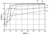
- FIG. 3 is a graph showing the relationship between the wavelength of laser light and reflectance.
- FIG. 4 is a graph showing temporal changes in the total output of laser light.
- FIG. 5A is a diagram showing a state in which the first laser beam is made incident on the first core.
- FIG. 5B is a diagram illustrating a state in which the first laser beam is emitted from the first core;
- FIG. 6A is a diagram showing a state in which the first laser light is made incident on the first core and the second core.
- FIG. 5A is a diagram showing a state in which the first laser beam is made incident on the first core and the second core.
- FIG. 6B is a diagram showing a state in which the first laser light is emitted from the first core and the second core
- FIG. 7A is a diagram showing a state in which the second laser beam is made incident on the first core and the first laser beam is made incident on the second core
- FIG. 7B is a diagram showing a state in which the first laser light is emitted from the second core while the second laser light is emitted from the first core.
- FIG. 8A is a diagram showing a state in which the output of the second laser beam to be incident on the first core is increased.
- FIG. 8B is a diagram showing a state in which the output of the second laser light is increased while moving the emission positions of the first laser light and the second laser light.
- the laser processing device 1 includes an optical coupling unit 10, a transmission fiber 20, a laser processing head 30, a robot 2, and a controller 5.
- the optical coupling unit 10 includes a first laser oscillator 11, a second laser oscillator 12, a first mirror 13, a second mirror 14, a third mirror 15, a first adjustment mechanism 16, and a second adjustment mechanism 17. and a third adjusting mechanism 18 .
- the first laser oscillator 11 emits the first laser beam L1 based on the command from the control unit 5.
- the first laser beam L1 is a short wavelength laser beam.
- the short-wavelength first laser light L1 is blue laser light or green laser light with a wavelength of 600 nm or less (for example, 266 nm to 600 nm).
- the first laser oscillator 11 emits a plurality of first laser beams L1 from a plurality of laser modules (not shown).
- the second laser oscillator 12 emits the second laser beam L2 based on the command from the control unit 5.
- the second laser beam L2 is a long-wavelength laser beam having a longer wavelength than the first laser beam L1.
- the long-wavelength second laser light L2 is infrared laser light with a wavelength of 800 nm or more (for example, about 800 nm to 16000 nm).
- the first mirror 13 reflects some of the first laser beams L1 emitted from the first laser oscillator 11 and guides them to the first adjustment mechanism 16 .
- the second mirror 14 reflects the remaining first laser beams L1 out of the plurality of first laser beams L1 emitted from the first laser oscillator 11 and guides them to the second adjustment mechanism 17 .
- the third mirror 15 reflects the second laser beam L2 emitted from the second laser oscillator 12 and guides it to the third adjustment mechanism 18 .
- the first adjustment mechanism 16 is composed of, for example, a two-axis MEMS (Micro Electro Mechanical Systems) mirror.
- the first adjustment mechanism 16 further reflects the first laser beam L ⁇ b>1 reflected by the first mirror 13 and guides it to the transmission fiber 20 .
- the first adjustment mechanism 16 changes the incident position of the first laser beam L1 with respect to the transmission fiber 20 by changing the angle of the mirror. This allows the first laser beam L1 to selectively enter the first core 21 or the second core 22 of the transmission fiber 20 .
- the second adjustment mechanism 17 is composed of, for example, a two-axis MEMS mirror.
- the second adjustment mechanism 17 further reflects the first laser beam L ⁇ b>1 reflected by the second mirror 14 and guides it to the transmission fiber 20 .
- the second adjustment mechanism 17 changes the incident position of the first laser beam L1 with respect to the transmission fiber 20 by changing the angle of the mirror. This allows the first laser beam L1 to selectively enter the first core 21 or the second core 22 of the transmission fiber 20 .
- the third adjustment mechanism 18 is composed of, for example, a two-axis MEMS mirror.
- the third adjustment mechanism 18 further reflects the second laser beam L2 reflected by the third mirror 15 and guides it to the transmission fiber 20 .
- the third adjustment mechanism 18 changes the incident position of the second laser beam L2 with respect to the transmission fiber 20 by changing the angle of the mirror. This allows the second laser light L2 to selectively enter the first core 21 or the second core 22 of the transmission fiber 20 .
- first adjustment mechanism 16, the second adjustment mechanism 17, and the third adjustment mechanism 18 may be configured using a biaxial galvanometer (galvanomirror) instead of the biaxial MEMS mirror.
- the optical coupling unit 10 and the laser processing head 30 are connected by a transmission fiber 20.
- the first laser beam L ⁇ b>1 and the second laser beam L ⁇ b>2 are transmitted to the laser processing head 30 via the transmission fiber 20 .
- the transmission fiber 20 has a first core 21 , a second core 22 , a first clad 23 , a second clad 24 and a protective coating 25 .
- the first core 21 is arranged at the axial center of the transmission fiber 20 .
- the first core 21 is formed in a circular shape when viewed from the axial direction.
- the first core 21 is made of quartz glass, for example.
- a first clad 23 is provided on the outer periphery of the first core 21 .
- the first clad 23 is provided coaxially with the first core 21 .
- the first clad 23 is made of a material having a lower refractive index than the first core 21 .
- the first clad 23 is made of, for example, fluorine-doped quartz glass. The refractive index of the first clad 23 is lower than that of the first core 21 .
- a second core 22 is provided on the outer periphery of the first clad 23 .
- the second core 22 is provided coaxially with the first core 21 .
- the second core 22 is formed in a ring shape when viewed from the axial direction.
- the second core 22 is made of the same material as the first core 21, such as quartz glass.
- the refractive index of the second core 22 is higher than that of the first clad 23 .
- a second clad 24 is provided on the outer periphery of the second core 22 .
- the second clad 24 is provided coaxially with the first core 21 and the second core 22 .
- the second clad 24 is made of, for example, fluorine-doped quartz glass.
- the refractive index of the second clad 24 is lower than that of the second core 22 .
- a protective film 25 is provided on the outer peripheral portion of the second clad 24 .
- the protective film 25 is made of synthetic resin, for example.
- the protective film 25 mechanically protects the first core 21, the second core 22, the first clad 23, and the second clad 24 made of quartz glass.
- the protective coating 25 prevents the first laser beam L1 and the second laser beam L2 from leaking from the transmission fiber 20 and prevents light from leaking into the transmission fiber 20 from the outside.
- the laser processing head 30 emits a first laser beam L1 and a second laser beam L2 incident from the transmission fiber 20 to the work W.
- the laser beam is emitted with the outer peripheral portion of the circular second laser beam L2 surrounded by the ring-shaped first laser beam L1.
- the laser processing head 30 has a collimator lens 31 , a fourth mirror 32 and a condenser lens 33 .
- the collimator lens 31 collimates the first laser beam L1 and the second laser beam L2 emitted from the emission end of the transmission fiber 20 .
- the fourth mirror 32 reflects the first laser beam L1 and the second laser beam L2 collimated by the collimator lens 31 and guides them to the condenser lens 33 .
- the condenser lens 33 condenses the first laser beam L1 and the second laser beam L2.
- the first laser beam L1 and the second laser beam L2 condensed by the condensing lens 33 are emitted to the work W. As shown in FIG.
- the robot 2 has a robot arm 3.
- a laser processing head 30 is attached to the tip of the robot arm 3 .
- the robot arm 3 has multiple joints 4 .
- the robot 2 changes the position of the laser processing head 30 with respect to the workpiece W by moving the laser processing head 30 along a predetermined welding direction (processing direction) based on a command from the control unit 5 .
- processing direction processing direction
- the emission positions of the first laser beam L1 and the second laser beam L2 with respect to the workpiece W are moved, and laser processing is performed.
- the controller 5 is connected to the optical coupling unit 10, the laser processing head 30, and the robot 2.
- the controller 5 controls the operations of the optical coupling unit 10 , the laser processing head 30 and the robot 2 .
- control unit 5 controls the output start and stop of the first laser beam L1 and the second laser beam L2, the output intensity of the first laser beam L1 and the second laser beam L2, and the like. It also has the function to In addition, although the control part 5 has one structure here, you may comprise more than one.
- the workpiece W is formed in a plate shape, for example.
- the workpiece W is composed of a high reflectance material with a low laser absorption rate.
- the reflectance of the laser beam differs depending on the material of the workpiece W.
- copper (Cu), aluminum (Al), gold (Au), and silver (Ag) are laser beams compared to iron (Fe).
- Fe iron
- the reflectance (%) of the wavelength of light is high, in other words, it is a high reflectance material with low laser absorptance.
- iron (Fe) has a relatively low reflectance (%) of the wavelength of the laser light, in other words, it is a low reflectance material with a high laser absorptivity.
- the work W is made of copper, which is a high reflectance material with a low laser absorptance.
- the workpiece W may be made of gold or silver.
- the laser start position S may generate spatter.
- control is performed at the laser start position S to suppress the occurrence of spatter in the laser start process.
- the laser start process is shown in FIG.
- the control section 5 performs the first step between the time T1 when the laser light emission is started at the laser start position S and the time T2.
- the controller 5 controls the operation of the optical coupling unit 10 so that the first core 21 emits the first laser beam L1.
- the controller 5 operates the short-wavelength first laser oscillator 11 to emit a short-wavelength first laser beam L1, while the long-wavelength second laser oscillator 12 is stopped.
- the control unit 5 adjusts the angle of the mirror of the first adjustment mechanism 16 to cause the first laser beam L1 reflected by the first mirror 13 to enter the first core 21 formed at the axial center of the transmission fiber 20.
- the control unit 5 adjusts the angle of the mirror of the second adjustment mechanism 17 to cause the first laser beam L reflected by the second mirror 14 to enter the first core 21 of the transmission fiber 20 .
- the short-wavelength first laser beam L1 incident on the first core 21 is emitted to the workpiece W in a circular shape.
- a molten pool 40 in which the workpiece W is partially melted by the first laser beam L1 is formed at the laser starting position S of the workpiece W.
- the output of the first laser beam L1 is set to 0.5 kW to 4 kW, preferably 2 kW.
- the controller 5 performs the fourth step between time T2 and time T3.
- the control section 5 controls the operation of the optical coupling unit 10 so that the first laser light L1 is emitted from both the first core 21 and the second core 22 .
- the controller 5 operates the first short-wavelength laser oscillator 11 to emit a first short-wavelength laser beam L1, while the second long-wavelength laser oscillator 12 to stop the operation of
- the control unit 5 adjusts the angle of the mirror of the first adjusting mechanism 16 to cause the first laser beam L1 reflected by the first mirror 13 to enter the first core 21 of the transmission fiber 20 .
- the control unit 5 adjusts the angle of the mirror of the second adjustment mechanism 17 to cause the first laser beam L1 reflected by the second mirror 14 to enter the second core 22 .
- the short-wavelength first laser beam L incident on the first core 21 is emitted to the workpiece W in a circular shape.
- the short-wavelength first laser beam L1 that has entered the second core 22 is emitted toward the workpiece W in a ring shape.
- the beam diameter of the first laser beam L1 in the fourth step is the beam diameter of the first laser beam L1 in the first step ( 5B).
- a molten pool 40 larger than that in the first step is formed at the laser starting position S of the workpiece W.
- the emission range of the first laser beam L1 at the laser start position S is widened, and the power density of the laser is relatively lowered compared to the first step.
- the workpiece W can also be preheated.
- the control unit 5 performs the second step.
- the controller 5 causes the first core 21 to emit the long-wavelength second laser beam L2 and the second core 22 to emit the short-wavelength first laser beam L1. It controls the operation of the coupling unit 10 .
- the controller 5 operates the first short-wavelength laser oscillator 11 to emit a first short-wavelength laser beam L1, while the second long-wavelength laser oscillator 12 is operated to emit the long-wavelength second laser beam L2.
- the control unit 5 adjusts the angle of the mirror of the first adjustment mechanism 16 to direct the first short-wavelength laser light L1 reflected by the first mirror 13 to be coaxial with the first core 21 of the transmission fiber 20 and at the same position as the first laser beam L1.
- the light is made incident on the second core 22 provided on the outer peripheral side of the first core 21 .
- the controller 5 adjusts the angle of the mirror of the second adjustment mechanism 17 to cause the first short-wavelength laser beam L1 reflected by the second mirror 14 to enter the second core 22 of the transmission fiber 20 .
- the control unit 5 adjusts the angle of the mirror of the third adjustment mechanism 18 to direct the second long-wavelength laser beam L2 reflected by the third mirror 15 to the first core 21 provided at the axial center of the transmission fiber 20. be incident on the
- the long-wavelength second laser beam L2 incident on the first core 21 provided at the axial center of the transmission fiber 20 is emitted to the workpiece W in a circular shape. be.
- the short-wavelength first laser beam L1 that has entered the second core 22 is emitted toward the workpiece W in a ring shape.
- a molten pool 40 is formed with a large amount of penetration due to the high output of the long-wavelength second laser beam L2.
- the output of the second laser beam L2 is set to 4 kW, for example.
- the beam diameter of the short-wavelength first laser beam L1 is reduced with respect to the workpiece W made of the highly reflective material, and the workpiece W is partially melted to form the Then, the beam diameter of the first laser beam L1 is increased, and the power density of the laser is relatively lowered to promote preheating of the work W. As shown in FIG.
- the molten pool 40 of the workpiece W is subjected to a long A second laser beam L2 with a wavelength is emitted, and a first laser beam L1 with a short wavelength is emitted in a ring shape around the laser beam L1 to form a molten pool 40 with a large amount of penetration.
- the amount of penetration is increased, and the opening of the keyhole (not shown) formed in the molten pool 40 is widened by widening the inclination of the peripheral edge of the opening of the keyhole, thereby stabilizing the molten metal vapor in the keyhole.
- the generation of spatter at the laser start position S in the laser start process can be suppressed, and the processing quality of the work W can be improved.
- the second it is possible to clean the processing surface behind the second laser beam L2 while preheating the front portion of the laser beam L2.
- the control unit 5 performs the third step between time T3 and time T4.
- the control unit 5 causes the first core 21 provided at the axial center of the transmission fiber 20 to emit the second laser light L2 having a long wavelength, while the second laser light L2 provided on the outer periphery of the first core 21
- the operation of the optical coupling unit 10 is controlled so that the short wavelength first laser light L1 is emitted from the two cores 22 .
- the control unit 5 gradually increases the output of the long-wavelength second laser beam L2 emitted from the first core 21 provided at the axial center of the transmission fiber 20. increase.
- the controller 5 operates the first laser oscillator 11 to emit the first laser beam L1, and operates the second laser oscillator 12 to emit the second laser beam L2. is emitted.
- the control unit 5 adjusts the angle of the mirror of the first adjustment mechanism 16 to direct the first short-wavelength laser light L1 reflected by the first mirror 13 to be coaxial with the first core 21 of the transmission fiber 20 and at the same position as the first laser beam L1.
- the light is made incident on the second core 22 provided on the outer peripheral side of the first core 21 .
- the controller 5 adjusts the angle of the mirror of the second adjustment mechanism 17 to cause the first short-wavelength laser beam L1 reflected by the second mirror 14 to enter the second core 22 of the transmission fiber 20 .
- the controller 5 adjusts the angle of the mirror of the third adjusting mechanism 18 to cause the second long-wavelength laser beam L2 reflected by the third mirror 15 to enter the first core 21 of the transmission fiber 20 .
- the long-wavelength second laser beam L2 incident on the first core 21 provided at the axial center of the transmission fiber 20 is emitted to the workpiece W in a circular shape. be.
- the short-wavelength first laser beam L1 that has entered the second core 22 is emitted toward the workpiece W in a ring shape.
- the control unit 5 controls the operation of the second laser oscillator 12 to increase the output of the second long-wavelength laser beam L2 incident on the first core 21 .
- the output of the second laser beam L2 is set to 10 kW, for example.
- the output of the second laser beam L2 at time T4 is greater than the output of the second laser beam L2 at time T3. Therefore, the total output P2 of the laser light at time T4 is larger than the total output P1 of the laser light at time T3.
- the control unit 5 controls the operation of the second laser oscillator 12 so that the total output of laser light gradually changes from P1 to P2 from time T3 to time T4.
- a molten pool 40 is formed in the work W at the position where the first short-wavelength laser beam L1 and the second long-wavelength laser beam L2 are emitted.
- a weld bead 41 is formed on the workpiece W behind the molten pool 40 in the welding direction by the solidification of the molten pool 40 .
- the output of the laser light is gradually increased.
- a sufficient penetration depth of the workpiece W can be ensured while moving the machining head 30 in the welding direction.
- the embodiment may be configured as follows.
- the first step of emitting the short-wavelength first laser beam L1 from the first core 21 is performed between the time T1 and the time T2, and the short-wavelength first laser beam L1 is emitted between the time T2 and the time T3.
- a fourth step of emitting the laser light L1 from the first core 21 and the second core 22 is performed, and at time T3, the short wavelength first laser light L1 is emitted from the second core 22, while the long wavelength second laser light L1
- a second step of emitting the light L2 from the first core 21 is performed, and between time T3 and time T4, the emission positions of the first laser light L1 and the second laser light L2 with respect to the workpiece W are moved in the laser processing direction.
- the third step of gradually increasing the output of the second laser beam L2 emitted from the first core 21 is performed, but the present invention is not limited to this form.
- the second step may be performed without performing the fourth step. That is, the first step may be performed between time T1 and time T3, the second step may be performed at time T3, and the third step may be performed between time T3 and time T4.
- the robot 2 moves the laser processing head 30 to change the position of the laser processing head 30 with respect to the work W, but the present invention is not limited to this form.
- the work W may be mounted on a moving table (not shown), and the work W may be moved relative to the laser processing head 30 .
- the laser processing head 30 and the moving table on which the work W is mounted are relatively moved, and the first laser beam L1 and the second laser beam L2 are moved relatively to the work W for processing.
- the present invention is not limited to this configuration.
- a configuration in which a laser processing head that emits the short-wavelength first laser beam L1 and a laser processing head that emits the long-wavelength second laser beam L2 are provided separately may be used.
- the present invention has a highly practical effect of being able to suppress the occurrence of spatter at the laser start position, so it is extremely useful and has high industrial applicability.
Landscapes
- Physics & Mathematics (AREA)
- Optics & Photonics (AREA)
- Engineering & Computer Science (AREA)
- Plasma & Fusion (AREA)
- Mechanical Engineering (AREA)
- Laser Beam Processing (AREA)
Priority Applications (2)
| Application Number | Priority Date | Filing Date | Title |
|---|---|---|---|
| CN202380018611.6A CN118660780A (zh) | 2022-02-02 | 2023-02-01 | 激光加工方法 |
| JP2023578577A JPWO2023149449A1 (https=) | 2022-02-02 | 2023-02-01 |
Applications Claiming Priority (2)
| Application Number | Priority Date | Filing Date | Title |
|---|---|---|---|
| JP2022014611 | 2022-02-02 | ||
| JP2022-014611 | 2022-02-02 |
Publications (1)
| Publication Number | Publication Date |
|---|---|
| WO2023149449A1 true WO2023149449A1 (ja) | 2023-08-10 |
Family
ID=87552415
Family Applications (1)
| Application Number | Title | Priority Date | Filing Date |
|---|---|---|---|
| PCT/JP2023/003153 Ceased WO2023149449A1 (ja) | 2022-02-02 | 2023-02-01 | レーザ加工方法 |
Country Status (3)
| Country | Link |
|---|---|
| JP (1) | JPWO2023149449A1 (https=) |
| CN (1) | CN118660780A (https=) |
| WO (1) | WO2023149449A1 (https=) |
Citations (3)
| Publication number | Priority date | Publication date | Assignee | Title |
|---|---|---|---|---|
| WO2017134964A1 (ja) * | 2016-02-05 | 2017-08-10 | 村田機械株式会社 | レーザ加工機およびレーザ加工方法 |
| JP2018174059A (ja) * | 2017-03-31 | 2018-11-08 | パナソニックIpマネジメント株式会社 | 溶接構造体及びその製造方法 |
| WO2019176502A1 (ja) * | 2018-03-15 | 2019-09-19 | パナソニックIpマネジメント株式会社 | レーザ発振器、それを用いたレーザ加工装置及びレーザ発振方法 |
-
2023
- 2023-02-01 CN CN202380018611.6A patent/CN118660780A/zh active Pending
- 2023-02-01 JP JP2023578577A patent/JPWO2023149449A1/ja active Pending
- 2023-02-01 WO PCT/JP2023/003153 patent/WO2023149449A1/ja not_active Ceased
Patent Citations (3)
| Publication number | Priority date | Publication date | Assignee | Title |
|---|---|---|---|---|
| WO2017134964A1 (ja) * | 2016-02-05 | 2017-08-10 | 村田機械株式会社 | レーザ加工機およびレーザ加工方法 |
| JP2018174059A (ja) * | 2017-03-31 | 2018-11-08 | パナソニックIpマネジメント株式会社 | 溶接構造体及びその製造方法 |
| WO2019176502A1 (ja) * | 2018-03-15 | 2019-09-19 | パナソニックIpマネジメント株式会社 | レーザ発振器、それを用いたレーザ加工装置及びレーザ発振方法 |
Also Published As
| Publication number | Publication date |
|---|---|
| JPWO2023149449A1 (https=) | 2023-08-10 |
| CN118660780A (zh) | 2024-09-17 |
Similar Documents
| Publication | Publication Date | Title |
|---|---|---|
| JP6602860B2 (ja) | レーザ加工装置及びレーザ加工方法 | |
| TWI789466B (zh) | 雷射焊接裝置及使用雷射束焊接工件的方法 | |
| JP6887502B2 (ja) | レーザ加工装置および方法 | |
| CN102164703A (zh) | 一种具有多个焦点的光纤激光切割方法 | |
| JP2020199513A (ja) | レーザ加工機及びレーザ加工機の制御方法 | |
| JP6393555B2 (ja) | レーザ加工機及びレーザ切断加工方法 | |
| JP7836964B2 (ja) | レーザ加工装置 | |
| JP7833648B2 (ja) | レーザ加工装置 | |
| WO2023149449A1 (ja) | レーザ加工方法 | |
| WO2023149451A1 (ja) | レーザ加工方法 | |
| JP6416801B2 (ja) | 加工ヘッドのアプローチ機能を有するレーザ加工機 | |
| JP7554973B2 (ja) | レーザ加工装置 | |
| JP2023112734A (ja) | レーザ加工方法 | |
| JP2023112733A (ja) | レーザ加工方法 | |
| JP2023112731A (ja) | レーザ加工装置 | |
| JP2023112742A (ja) | レーザ溶接装置及びこれを用いたレーザ溶接方法 | |
| JP2023112740A (ja) | レーザ装置及びこれを備えたレーザ加工装置 | |
| WO2021107043A1 (ja) | レーザ加工装置 | |
| JP2024019941A (ja) | レーザ加工装置 | |
| JP2024009490A (ja) | レーザ加工装置 | |
| JP2024072002A (ja) | レーザ加工装置及びレーザ加工方法 | |
| WO2025018106A1 (ja) | レーザ溶接装置およびレーザ溶接方法 | |
| JP2024019942A (ja) | レーザ加工装置 | |
| WO2023149452A1 (ja) | レーザ溶接方法 | |
| WO2015004718A1 (ja) | レーザ加工機、レーザ加工方法および加工ノズル |
Legal Events
| Date | Code | Title | Description |
|---|---|---|---|
| 121 | Ep: the epo has been informed by wipo that ep was designated in this application |
Ref document number: 23749765 Country of ref document: EP Kind code of ref document: A1 |
|
| ENP | Entry into the national phase |
Ref document number: 2023578577 Country of ref document: JP Kind code of ref document: A |
|
| WWE | Wipo information: entry into national phase |
Ref document number: 202380018611.6 Country of ref document: CN |
|
| NENP | Non-entry into the national phase |
Ref country code: DE |
|
| 122 | Ep: pct application non-entry in european phase |
Ref document number: 23749765 Country of ref document: EP Kind code of ref document: A1 |