WO2023148956A1 - 通信システム、通信装置、及び通信方法 - Google Patents
通信システム、通信装置、及び通信方法 Download PDFInfo
- Publication number
- WO2023148956A1 WO2023148956A1 PCT/JP2022/004621 JP2022004621W WO2023148956A1 WO 2023148956 A1 WO2023148956 A1 WO 2023148956A1 JP 2022004621 W JP2022004621 W JP 2022004621W WO 2023148956 A1 WO2023148956 A1 WO 2023148956A1
- Authority
- WO
- WIPO (PCT)
- Prior art keywords
- time
- communication
- application
- communication device
- local
- Prior art date
- Legal status (The legal status is an assumption and is not a legal conclusion. Google has not performed a legal analysis and makes no representation as to the accuracy of the status listed.)
- Ceased
Links
Images


Classifications
-
- H—ELECTRICITY
- H04—ELECTRIC COMMUNICATION TECHNIQUE
- H04J—MULTIPLEX COMMUNICATION
- H04J3/00—Time-division multiplex systems
- H04J3/02—Details
- H04J3/06—Synchronising arrangements
- H04J3/062—Synchronisation of signals having the same nominal but fluctuating bit rates, e.g. using buffers
- H04J3/0632—Synchronisation of packets and cells, e.g. transmission of voice via a packet network, circuit emulation service [CES]
-
- H—ELECTRICITY
- H04—ELECTRIC COMMUNICATION TECHNIQUE
- H04J—MULTIPLEX COMMUNICATION
- H04J3/00—Time-division multiplex systems
- H04J3/02—Details
- H04J3/12—Arrangements providing for calling or supervisory signals
-
- H—ELECTRICITY
- H04—ELECTRIC COMMUNICATION TECHNIQUE
- H04W—WIRELESS COMMUNICATION NETWORKS
- H04W56/00—Synchronisation arrangements
- H04W56/001—Synchronization between nodes
- H04W56/0015—Synchronization between nodes one node acting as a reference for the others
-
- H—ELECTRICITY
- H04—ELECTRIC COMMUNICATION TECHNIQUE
- H04W—WIRELESS COMMUNICATION NETWORKS
- H04W56/00—Synchronisation arrangements
- H04W56/001—Synchronization between nodes
- H04W56/002—Mutual synchronization
Definitions
- the present disclosure relates to communication systems, communication devices, and communication methods.
- Patent Document 1 discloses one or more machines, one or more controllers that respectively control the one or more machines, communicates with the one or more controllers via a wired communication network, and communicates with the one or more machines via a wireless communication network.
- a machine control system is disclosed that includes a communication server that communicates with a machine control system.
- Each of the one or more controllers includes a motion module that executes a motion program in a control cycle and generates a machine command for the corresponding machine, an addition unit that adds first cycle information to the machine command, and a machine command to the communication server. and a synchronous communication unit for transmission.
- Each of the one or more machines has a terminal communication unit that receives a machine command from the communication server, stores the machine command received by the terminal communication unit, and in a control cycle corresponding to first cycle information added to the machine command, a machine-side timing adjuster for invoking machine commands.
- the present disclosure provides an effective system for easily synchronizing applications that communicate with each other.
- a communication system is a system that performs wireless communication between a first application and a second application, and includes: a first communication device that performs first wired communication with the first application; and a second communication device that performs second wired communication with the first communication device and wirelessly communicates with the first communication device, the first communication device having a first time acquisition unit that acquires a first time from the first application , the second communication device includes a second time generation unit that generates a second time synchronized with the first time, and an interrupt output unit that periodically outputs an interrupt signal synchronized with the second time to the second application. have.
- a communication device performs wireless communication between a first application and a counterpart device that performs first wired communication, and transmits information acquired from the counterpart device through wireless communication to second wired communication through second wired communication.
- a second time generating unit for generating a second time synchronized with the first time obtained by the counterpart device from the first application, and an interrupt signal synchronized with the second time to the second application. and an interrupt output unit that outputs periodically.
- a communication method performs wireless communication between a first application and a counterpart device performing first wired communication, and transmits information acquired from the counterpart device through wireless communication to the second wired communication. generating a second time synchronized with the first time obtained by the counterpart device from the first application; and periodically sending an interrupt signal synchronized with the second time to the second application including outputting.
- an effective system is provided for easily synchronizing applications that communicate with each other.
- FIG. 1 is a schematic diagram illustrating a communication system
- FIG. 1 is a schematic diagram illustrating the configuration of a robot
- FIG. 3 is a block diagram illustrating functional configurations of a controller and a local controller
- FIG. 2 is a block diagram illustrating functional configurations of a first communication device and a second communication device
- FIG. 11 is a block diagram showing a modification of the second communication device
- It is a block diagram which illustrates the hardware constitutions of a controller and a 1st communication apparatus.
- 4 is a block diagram illustrating hardware configurations of a second communication device and a local controller
- FIG. 1 is a schematic diagram illustrating a communication system
- FIG. 1 is a schematic diagram illustrating the configuration of a robot
- FIG. 3 is a block diagram illustrating functional configurations of a controller and a local controller
- FIG. 2 is a block diagram illustrating functional configurations of a first communication device and a second communication device
- FIG. 11 is a block diagram showing a modification of
- 9 is a flowchart illustrating a procedure for synchronizing communication reference time; 9 is a flowchart illustrating a second time synchronization procedure; 10 is a flow chart illustrating an interrupt output procedure; 4 is a flowchart illustrating a local time synchronization procedure; 4 is a flow chart illustrating a host control procedure; 4 is a flow chart illustrating a local control procedure;
- a communication system 1 shown in FIG. 1 is a system that performs wireless communication between one application (first application) and another application (second application).
- the first application executes the first process including transmission and reception of information with the second application in synchronization with the first application time.
- the "time” is numerical information representing the current time by the elapsed time from the past reference time. The same applies to the following.
- the first application repeatedly executes the first process at the timing when the first application time satisfies a predetermined first process condition.
- the first processing condition may be that the first application time is a multiple of a predetermined first period. In this case, the first application repeatedly executes the first process in the first cycle.
- the second application executes the second process including transmission and reception of information with the first application in synchronization with the time of the first application.
- the second application repeatedly executes the second process at timing when the first application time satisfies a predetermined second process condition.
- the second processing condition may be that the first application time is a multiple of a predetermined second period. In this case, the second application repeatedly executes the second process in the second cycle.
- the communication system 1 includes a first communication device 200 and a second communication device 400.
- the first communication device 200 performs first wired communication with the first application.
- the second communication device 400 performs second wired communication with the second application and wireless communication with the first communication device.
- FIG. 1 illustrates a control system 10.
- the control system 10 comprises a controller 100 , a local controller 300 , a first communication device 200 and a second communication device 400 .
- the controller 100 performs the first wired communication with the first communication device 200 as the first application.
- the local controller 300 performs the second wired communication with the second communication device 400 as a second application.
- the controller 100 generates command data sets for the machine 30 (local device).
- the first communication device 200 receives the command data set from the controller 100 through first wired communication, and transmits the received command data set to the second communication device 400 through wireless communication.
- the local controller 300 receives the command data set received by the second communication device 400 via wireless communication from the second communication device 400 via second wired communication, and controls the machine 30 based on the received command data set.
- the local controller 300 may obtain from the machine 30 a feedback data set representing the operation result of the machine 30 .
- the second communication device 400 may receive the feedback data set from the local controller 300 through the second wired communication and transmit the received feedback data set to the first communication device 200 through wireless communication.
- the controller 100 receives the command data set received by the first communication device 200 via wireless communication from the first communication device 200 via the first wired communication, and generates the next command data set based on the received feedback data set.
- the control system 10 may include multiple local controllers 300 that operate multiple machines 30 respectively.
- the communication system 1 may include a plurality of second communication devices 400 corresponding to the plurality of local controllers 300 respectively.
- the first communication device 200 wirelessly communicates with each of the plurality of second communication devices 400 .
- the machine 30 is a machine that realizes actions. Although the type of machine 30 is not particularly limited, two types of machines 30A and 30B are illustrated in FIG.
- the machine 30A is a mobile robot that works on a work while moving.
- machine 30A has automatic guided vehicle 31 and robot 40 .
- the automatic guided vehicle 31 is driven by the local controller 300 to move.
- the robot 40 is installed on the unmanned guided vehicle 31.
- the robot 40 is driven by the local controller 300 to carry out work such as transportation, processing, and assembly of the work.
- the robot 40 is, for example, a vertically articulated industrial robot. As shown in FIG. 2 , the robot 40 has a base portion 41 , a turning portion 42 , a first arm 43 , a second arm 44 , a wrist portion 45 and a tip portion 46 .
- the base 41 is installed on the automatic guided vehicle 31 .
- the swivel part 42 is mounted on the base part 41 so as to be rotatable around the vertical axis 51 .
- the robot 40 has a joint 61 that attaches the pivot 42 to the base 41 so as to be rotatable about the axis 51 .
- the first arm 43 is connected to the swivel portion 42 so as to be rotatable about an axis 52 that intersects (for example, is perpendicular to) the axis 51 .
- the robot 40 has a joint 62 that connects the first arm 43 to the pivot 42 so as to be rotatable about the axis 52 .
- An intersection includes being in a twisted relationship, such as a so-called overpass. The same applies to the following.
- the first arm 43 extends from the turning portion 42 along one direction that intersects (for example, orthogonally) the axis 52 .
- the second arm 44 is connected to the end of the first arm 43 so as to be rotatable around an axis 53 parallel to the axis 52 .
- the robot 40 has a joint 63 connecting the second arm 44 to the first arm 43 so as to be rotatable about the axis 53 .
- the second arm 44 includes an arm base 47 extending from the end of the first arm 43 along one direction intersecting (for example, perpendicular to) the axis 53 and an arm further extending from the end of the arm base 47 along the same one direction. and end 48 .
- Arm end 48 is rotatable about axis 54 with respect to arm base 47 .
- Axis 54 intersects (eg, is orthogonal to) axis 53 .
- robot 40 has a joint 64 that connects arm end 48 to arm base 47 such that arm end 48 is rotatable about axis 54 .
- the wrist 45 is connected to the end of the arm end 48 so as to be rotatable about an axis 55 that intersects (for example, is perpendicular to) the axis 54 .
- the robot 40 has a joint 65 that connects the arm end 48 such that the wrist 45 is rotatable about the axis 55 .
- Wrist 45 extends from the end of arm end 48 along a direction that intersects (eg, is perpendicular to) axis 55 .
- the tip 46 is connected to the end of the wrist 45 so as to be rotatable about an axis 56 that intersects (eg, is perpendicular to) the axis 55 .
- robot 40 has a joint 66 that connects tip 46 to wrist 45 such that tip 46 is rotatable about axis 56 .
- An end effector is provided at the distal end portion 46 .
- Specific examples of the end effector include a hand for gripping a work, a work tool for processing and assembling a work, and the like.
- Actuators 71 , 72 , 73 , 74 , 75 , 76 drive joints 61 , 62 , 63 , 64 , 65 , 66 .
- Each of the actuators 71, 72, 73, 74, 75, 76 has, for example, an electric motor and a transmission section (for example, reduction gear) that transmits the power of the electric motor to the joints 61, 62, 63, 64, 65, 66. .
- actuator 71 drives joint 61 to rotate pivot 42 about axis 51 .
- Actuator 72 drives joint 62 to rotate first arm 43 about axis 52 .
- Actuator 73 drives joint 63 to rotate second arm 44 about axis 53 .
- Actuator 74 drives joint 64 to rotate arm end 48 about axis 54 .
- Actuator 75 drives joint 65 to rotate wrist 45 about axis 55 .
- Actuator 76 drives joint 66 to rotate tip 46 about axis 56 .
- the machine 30B is an unmanned guided vehicle that transports objects such as workpieces.
- the machine 30B has an automatic guided vehicle 33 and a loading table 34 .
- the automatic guided vehicle 33 is driven by the local controller 300 to move.
- the loading platform 34 is provided on the automatic guided vehicle 33 and supports the object to be transported.
- the controller 100 performs host processing (first processing) including generation of command data sets in synchronization with the host time (first application time). For example, the controller 100 generates a command data set based on the feedback data set every time the host time becomes a multiple of a predetermined host control cycle (first cycle), and transmits the generated command data set to the first communication device 200. do.
- the local controller 300 performs local processing (second processing) including controlling the machine 30 based on the command data set in synchronization with the host time. For example, the local controller 300 controls the machine 30 based on the command data set every time the host time becomes a multiple of a predetermined local control period (second period), obtains the feedback data set from the machine 30, and obtains the feedback data set. Sending the data set to the second communication device 400 .
- the local control period may be the same as the host control period.
- the local controller 300 may generate a local time synchronized with the host time and perform local processing in synchronization with the local time. For example, the local controller 300 may control the machine 30 based on the command data set and obtain a feedback data set from the machine 30 each time the local time is a multiple of the local control period.
- the controller 100 may add command timing information that determines the read timing of the command data set (hereinafter referred to as "command timing") to the command data set and transmit it to the first communication device 200.
- command timing determines the read timing of the command data set
- the local controller 300 receives and holds the command data set from the second communication device 400, and reads the command data set at the command timing based on the local time and the command timing information.
- the local controller 300 controls the machine 30 based on the command data set read at command timing.
- the command timing information may be information that indirectly specifies the command timing.
- the command timing information may be information representing command reference timing before the timing at which the controller 100 transmits the command data set to the first communication device 200 . If the delay time from the command reference timing to the command timing is predetermined, the command timing is indirectly determined by the command reference timing.
- a specific example of the command reference timing is the timing at which the controller 100 generated the command data set.
- the local controller 300 may add feedback timing information that determines the read timing of the feedback data set (hereinafter referred to as "feedback timing") to the feedback data set and transmit it to the second communication device 400.
- the controller 100 receives and holds the feedback data set from the first communication device 200, and reads the feedback data set at the feedback timing based on the host time and the feedback timing information.
- the local controller 300 generates a command data set based on the feedback data set read at the feedback timing.
- the feedback timing information may be information that indirectly specifies the feedback timing.
- the feedback timing information may be information representing feedback reference timing before the timing at which the local controller 300 transmits the feedback data set to the second communication device 400 . If the delay time from the feedback reference timing to the feedback timing is determined in advance, the feedback timing is indirectly determined by the feedback reference timing.
- a specific example of the feedback reference timing is the timing at which the local controller 300 acquires the feedback data set.
- FIG. 3 is a block diagram illustrating functional configurations of the controller 100 and the local controller 300.
- the controller 100 includes, as functional components (hereinafter referred to as “functional blocks”), a host time generation unit 111, a reception data acquisition unit 112, a standby buffer 113, and a reading unit 114. , and a control calculation unit 115 .
- the host time generation unit 111 generates host time. For example, the host time generator 111 counts clock pulses and generates the host time based on the count result and the period of the clock pulses.
- the received data acquisition unit 112 acquires the feedback data set from the first communication device 200 and stores it in the standby buffer 113 . When storing the feedback data set in the standby buffer 113, the received data acquisition unit 112 may convert the feedback timing information into the number of cycles of the host control period from the current time to the feedback timing.
- the reading unit 114 reads the feedback data set from the standby buffer 113 at the feedback timing based on the host time and the feedback timing information. For example, if the feedback timing information is converted into the number of cycles of the host control period, the reading unit 114 counts down the feedback timing information each time the host time becomes a multiple of the host control period. Accordingly, when the feedback timing information becomes zero, the reading unit 114 reads the feedback data set from the standby buffer 113 .
- the delay time from the transmission of the feedback data set by the local controller 300 to the reception of the feedback data set by the controller 100 may vary. Even if the delay time varies, the received feedback data set is read at the timing determined by the feedback timing information. Therefore, the feedback data set can be read in synchronization with the host time without being affected by the variation in delay time.
- the control calculation unit 115 generates command data sets based on the feedback data sets read by the reading unit 114 .
- the control calculation unit 115 performs a proportional calculation, a proportional/integral calculation, or a proportional/integral/differential calculation on the deviation between the target operation and the operation of the machine 30 represented by the feedback data set to obtain a target output (for example, a target torque or a target Calculate a command data set representing current).
- a target output for example, a target torque or a target Calculate a command data set representing current.
- the control calculation unit 115 generates the command data set in synchronization with the host time. For example, the control calculation unit 115 generates a command data set based on the feedback data set read by the reading unit 114 each time the host time becomes a multiple of the host control period.
- the control calculation unit 115 adds the command timing information to the generated command data set.
- the control calculation unit 115 transmits the command data set to which the command timing information is added to the first communication device 200 .
- the controller 100 may have a plurality of control modules 110 respectively corresponding to the plurality of local controllers 300.
- Each of the plurality of control modules 110 has a host time generation section 111 , a received data acquisition section 112 , a standby buffer 113 , a reading section 114 and a control calculation section 115 .
- the controller 100 may be configured such that one host time generator 111 is shared by a plurality of control modules 110 .
- the local controller 300 includes a local time generation unit 311, a received data acquisition unit 312, a standby buffer 313, a reading unit 314, and a control unit 315 as functional blocks.
- the local time generation unit 311 generates local time synchronized with the host time. For example, the local time generator 311 counts clock pulses and generates local time based on the count result and the period of the clock pulses.
- the received data acquisition unit 312 acquires the command data set from the second communication device 400 and stores it in the standby buffer 313 . When the command data set is stored in the standby buffer 313, the received data acquisition unit 312 may convert the command timing information into the number of cycles of the local control period from the current time to the command timing.
- the reading unit 314 reads the command data set from the standby buffer 313 at the command timing based on the local time and the command timing information. For example, when the command timing information is converted into the number of cycles of the local control period, the reading unit 314 counts down the command timing information each time the local time becomes a multiple of the local control period. As a result, when the command timing information becomes zero, the reading unit 314 reads the command data set from the standby buffer 313 .
- the delay time from the transmission of the command data set by the controller 100 to the reception of the feedback data set by the local controller 300 may vary. Even if the delay time varies, the received command data set is read at the timing determined by the command timing information. Therefore, the command data set can be read in synchronization with the local time without being affected by the variation in delay time.
- the control unit 315 controls the machine 30 based on the command data set read by the reading unit 314 .
- the control unit 315 controls the machine 30 with an output corresponding to the target output, and obtains from the machine 30 a feedback data set representing the operation result of the machine 30 .
- the control unit 315 adds the feedback timing information to the acquired feedback data set.
- the control unit 315 transmits the feedback data set with the feedback timing information to the second communication device 400 .
- the controller 100 and local controller 300 are merely examples of the first application and the second application.
- the first application and the second application may be anything as long as they communicate via the communication system 1 and perform their respective processes in synchronization with a common time.
- the communication system 1 In order for the first application and the second application to execute processing synchronized with the common time, the communication system 1 needs to provide the first application time information from the first application to the second application. However, since there is a delay from the time when the first application transmits the information of the first application time until the second application receives the information of the first application time, simply transmitting and receiving the information of the first application time , the first application and the second application cannot be synchronized to a common time.
- time synchronization is performed between the first application and the first communication device 200, between the first communication device 200 and the second communication device 400, and between the second communication device 400 and the second application. It is necessary to perform communication that guarantees reliability (communication that compensates for delay time).
- a specific example of communication that guarantees time synchronization is TSN (Time Sensitive Networking) communication.
- the second application may not have the function of performing communication that guarantees time synchronization. Therefore, the first communication device 200 is configured to acquire the first time from the first application (eg, the controller 100). The second communication device 400 generates a second time synchronized with the first time, and periodically outputs an interrupt signal synchronized with the second time to the second application (for example, the local controller 300). configured to run.
- the first application eg, the controller 100
- the second communication device 400 generates a second time synchronized with the first time, and periodically outputs an interrupt signal synchronized with the second time to the second application (for example, the local controller 300). configured to run.
- the configurations of the first communication device 200 and the second communication device 400 will be illustrated in detail below with reference to FIG.
- the first communication device 200 and the second communication device 400 perform mobile communication as an example of wireless communication.
- the first communication device 200 is a base station for mobile communication
- the second communication device 400 is a mobile station for mobile communication.
- the first communication device 200 transmits a communication packet received from the controller 100 via a communication line 201 (described later) to the second communication device 400 via wireless communication, and transmits a communication packet received from the second communication device 400 via wireless communication to the communication line. 201 to the controller 100 .
- the second communication device 400 transmits the communication packet received from the first communication device 200 by wireless communication to the local controller 300 via the communication line 401, and transmits the communication packet received from the local controller 300 via the communication line 401 to the first communication device by wireless communication. Send to communication device 200 .
- the first communication device 200 and the second communication device 400 may perform wireless communication based on a common communication reference time.
- the first communication device 200 and the second communication device 400 perform communication (5G communication) by the fifth generation mobile communication system based on the communication reference time.
- the first communication device 200 and the second communication device 400 may perform local mobile communication synchronized with public mobile communication performed by a public base station different from the first communication device 200 based on the communication reference time.
- An example of public mobile communication performed by a public base station includes mobile communication performed between a base station of a carrier and a mobile communication terminal such as a smart phone.
- the first communication device 200 and the second communication device 400 perform local 5G communication synchronized with public 5G communication performed by public base stations.
- the first communication device 200 and the second communication device 400 perform local 5G communication in a time division duplex pattern synchronized with the time division duplex pattern of public 5G communication.
- the first communication device 200 includes, as functional blocks, a reference time generation unit 211, a transmission buffer 212, a wireless communication unit 213, a reception buffer 214, a first time acquisition unit 215, a timing and an information output unit 216 .
- the reference time generator 211 generates base station time (communication reference time).
- the reference time generator 211 acquires the global time from the time server 101 through TSN communication or the like, and generates the base station time synchronized with the global time.
- Global time is the time with which the public mobile communications are synchronized.
- the global time is the time at which the time division duplex pattern of the public 5G communication is synchronized.
- the transmission buffer 212 temporarily stores the command data set transmitted from the control calculation section 115 of the controller 100 .
- the wireless communication unit 213 reads the command data set from the transmission buffer 212 and transmits the read command data set to the second communication device 400 by wireless communication. Also, the wireless communication unit 213 receives the feedback data set from the second communication device 400 by wireless communication. The wireless communication unit 213 transmits the command data set and receives the feedback data set by wireless communication in synchronization with the base station time generated by the reference time generation unit 211 .
- the reception buffer 214 temporarily stores the feedback data set received by the wireless communication unit 213 .
- the reception data acquisition unit 112 of the controller 100 acquires the feedback data set from the reception buffer 214 .
- the first time acquisition unit 215 acquires the first time from the first application. For example, the first time acquisition unit 215 acquires the first time synchronized with the host time from the host time generation unit 111 through TSN communication or the like.
- the timing information output unit 216 calculates the time difference between the first time acquired by the first time acquisition unit 215 and the base station time generated by the reference time generation unit 211, and generates time difference information representing the calculated time difference as host time.
- the second communication device 400 is caused to transmit by the unit 111 .
- the first time acquisition unit 215 may further acquire interrupt timing information representing the relationship between the first time and the output timing of the interrupt signal from the first application.
- the first time acquisition unit 215 acquires interrupt timing information from the host time generation unit 111 .
- the interrupt timing information may include the output start timing of the interrupt signal and the output cycle of the interrupt signal.
- the timing information output unit 216 causes the wireless communication unit 213 to transmit the interrupt timing information acquired by the first time acquisition unit 215 to the second communication device 400 .
- the second communication device 400 includes, as functional blocks, a reference time generation unit 411, a transmission buffer 412, a wireless communication unit 413, a reception buffer 414, a timing information acquisition unit 415, a second time generation unit 416, an interrupt and an output unit 417 .
- the reference time generator 411 generates mobile station time synchronized with the base station time.
- the transmission buffer 412 temporarily stores the feedback data set transmitted from the control unit 315 of the local controller 300 .
- the wireless communication unit 413 reads the feedback data set from the transmission buffer 412 and transmits the read feedback data set to the wireless communication unit 213 of the first communication device 200 by wireless communication. Also, the wireless communication unit 413 receives the command data set from the wireless communication unit 213 by wireless communication.
- the wireless communication unit 413 transmits the feedback data set and receives the command data set by wireless communication in synchronization with the mobile station time generated by the reference time generation unit 411 .
- the reception buffer 414 temporarily stores the command data set received by the wireless communication unit 413 .
- the reception data acquisition unit 312 of the local controller 300 acquires the command data set from the reception buffer 414 .
- the above-described reference time generation unit 411 obtains the base station time from the reference time generation unit 211 by TSN communication or the like via wireless communication by the wireless communication unit 213, and synchronizes with the base station time. Generate mobile station time.
- the timing information acquisition unit 415 acquires the time difference information and the interrupt timing information received by the wireless communication unit 413 from the wireless communication unit 213 .
- a second time generator 416 generates a second time synchronized with the first time. For example, the second time generation unit 416 generates the second time based on the time difference information acquired by the timing information acquisition unit 415 and the mobile station time generated by the reference time generation unit 411 . For example, the second time generator 416 generates the second time by shifting the mobile station time according to the time difference indicated by the time difference information.
- the interrupt output unit 417 periodically outputs an interrupt signal synchronized with the second time to the local controller 300 .
- the interrupt output unit 417 may output the interrupt signal to the second application such that the relationship between the second time and the output timing is represented by the interrupt timing information.
- the interrupt timing information may include output start timing and output period.
- the interrupt output unit 417 may output an interrupt signal to the local controller 300 every time the elapsed time from the output start timing becomes a multiple of the output period based on the second time.
- the local controller 300 may control the machine 30 at timing based on the interrupt signal.
- the interrupt signal is output in synchronization with the second time.
- the second time is generated so as to synchronize with the first time. For this reason, even in the local controller 300 that does not have a function to perform communication that guarantees time synchronization with the second communication device 400, by controlling the machine 30 at the timing based on the interrupt signal, it is possible to acquire from the controller 100 It becomes possible to control the machine 30 in synchronization with the set first time.
- the interrupt output unit 417 may output an interrupt signal to the local controller 300 via an interrupt line 402 (described later) provided separately from the communication line 401 (described later).
- the interrupt output unit 417 may transmit an interrupt packet containing an interrupt signal to the local controller 300 via the communication line 401 .
- the interrupt output unit 417 may transmit interrupt packets to the local controller 300 with priority over communication packets transmitted from the reception buffer 414 to the local controller 300 via the communication line 401 .
- the interrupt output unit 417 may interrupt transmission of the communication packet from the reception buffer 414 to the local controller 300 at the output timing of the interrupt signal and transmit the interrupt packet to the local controller 300 .
- the interrupt output unit 417 may be configured to execute both a dedicated output mode for outputting an interrupt signal via the interrupt line 402 and a packet output mode for transmitting an interrupt packet via the communication line 401 .
- the second communication device 400 may further have an output mode selector 421 .
- the output mode selection unit 421 selects either a dedicated output mode for outputting an interrupt signal via the interrupt line 402 or a packet output mode for transmitting an interrupt packet via the communication line 401 by a user input to a user interface 396 (described later). Choose based on
- the interrupt output unit 417 When the output mode selection unit 421 selects the dedicated output mode, the interrupt output unit 417 outputs an interrupt signal to the local controller 300 via the interrupt line 402 without transmitting an interrupt packet. When the output mode selection unit 421 selects the packet output mode, the interrupt output unit 417 transmits an interrupt packet to the local controller 300 via the communication line 401 without outputting an interrupt signal via the interrupt line 402 .
- the second communication device 400 may further have a time transmission unit 424.
- the time transmission unit 424 transmits time information representing the second time to the local controller 300 .
- the local controller 300 may generate the local time synchronized with the second time based on the time information and the interrupt signal, and control the machine 30 at the timing based on the local time.
- the time transmission unit 424 transmits time information representing the second time at the timing at which the interrupt output unit 417 outputs the interrupt signal to the local time generation unit 311 via the communication line 401 .
- the local time generator 311 generates (corrects) the local time so as to match the second time indicated by the time information at the time when the output of the interrupt signal is detected. According to the configuration for synchronizing the local time with the second time, the machine 30 can be controlled in synchronization with the second time in a control cycle shorter than the interrupt signal output cycle.
- the second communication device 400 may be configured to output to the local controller 300 synchronization status information indicating the state of synchronization of the second time with respect to the first time.
- the second communication device 400 may further have a status confirmation section 422 and a status output section 423 .
- the status confirmation unit 422 confirms the synchronization state of the second time with respect to the first time.
- the status confirmation unit 422 confirms whether the second time is synchronized with the first time based on whether the generation of the second time by the second time generation unit 416 has succeeded.
- the status confirmation unit 422 sets the confirmation result of the synchronization state to “synchronized”, and the second time generation unit 416 generates the second time. is successful, set the synchronization status check result to "asynchronous".
- the timing information acquisition unit 415 cannot acquire the time difference information due to packet loss or the like in wireless communication.
- the synchronization state may be a synchronization level that represents the accuracy of synchronization.
- the status confirmation unit 422 may evaluate the synchronization level based on the elapsed time after the second time generation unit 416 successfully generated the second time. For example, the status confirmation unit 422 sets the synchronization level to the highest level immediately after the second time generation unit 416 succeeds in generating the second time, and sets the synchronization level to the highest level until the second time generation unit 416 next succeeds in generating the second time. , the synchronization level may be gradually lowered over time.
- the status output unit 423 outputs synchronization status information indicating the synchronization state confirmed by the status confirmation unit 422 to the local controller 300 .
- the status output unit 423 may output synchronization status information to the local controller 300 via a status output line 403 (described later) provided separately from the communication line 401 (described later) and the interrupt line 402 (described later).
- the status output unit 423 may include synchronization status information in the interrupt packet.
- the synchronization status information is transmitted to the local controller 300 via the communication line 401.
- the second communication device 400 may further have a time synchronization unit 425.
- the time synchronization unit 425 is based on the communication delay time between the second communication device 400 and the local controller 300.
- the local time synchronized with the second time is generated in the local controller 300 .
- the time synchronization unit 425 corrects the second time using the communication delay time, calculates the corrected second time, and transmits the corrected second time to the local time generation unit 311 .
- the local time generator 311 generates local time synchronized with the second time based on the corrected second time.
- FIG. 6 is a block diagram illustrating the hardware configuration of the controller 100 and the first communication device 200. As shown in FIG. As shown in FIG. 6, controller 100 has circuitry 190 . Circuit 190 has processor 191 , memory 192 , storage 193 , communication port 194 and user interface 195 .
- the storage 193 is a non-volatile storage medium. Specific examples of the storage 193 include a hard disk, flash memory, and the like. The storage 193 may be a portable storage medium such as an optical disc. The storage 193 stores programs for causing the controller 100 to configure each functional block described above.
- the memory 192 is a temporary storage medium such as random access memory, and temporarily stores programs loaded from the storage 193 .
- the processor 191 is composed of one or more arithmetic elements, and executes a program loaded in the memory 192 to cause the controller 100 to configure each of the above functional blocks.
- the communication port 194 communicates with the first communication device 200 in response to requests from the processor 191 .
- the user interface 195 is a device for performing input by the user and presenting information to the user, and includes, for example, an input device and a display device.
- input devices include keyboards, mice, keypads, and the like.
- display devices include liquid crystal monitors and organic EL (Electro-Luminescence) monitors.
- the input device may be integrated with the display device as a so-called touch panel.
- the first communication device 200 has a circuit 290.
- Circuit 290 has processor 291 , memory 292 , storage 293 and communication port 294 .
- the storage 293 is a non-volatile storage medium. Specific examples of the storage 193 include a hard disk, flash memory, and the like. The storage 193 may be a portable storage medium such as an optical disc. The storage 293 stores a program for configuring each functional block described above in the first communication device 200 .
- the memory 292 is a temporary storage medium such as random access memory, and temporarily stores programs loaded from the storage 293 .
- the processor 291 is composed of one or more arithmetic elements, and executes a program loaded in the memory 292 to cause the first communication device 200 to configure each of the above functional blocks.
- Communication port 294 communicates with communication port 194 via communication line 201 in response to requests from processor 291 .
- the antenna 295 transmits and receives wireless communication signals to and from the second communication device 400 in response to a request from the processor 291 .
- FIG. 7 is a block diagram illustrating the hardware configuration of the local controller 300 and the second communication device 400.
- local controller 300 includes circuitry 390 .
- Circuitry 390 includes processor 391 , memory 392 , storage 393 , communications port 394 , drive circuitry 395 , user interface 396 , input port 397 and input port 398 .
- the storage 393 is a non-volatile storage medium. Specific examples of the storage 393 include a hard disk, flash memory, and the like. The storage 393 may be a portable storage medium such as an optical disc. The storage 393 stores programs for causing the local controller 300 to configure each functional block described above.
- the memory 392 is a temporary storage medium such as random access memory, and temporarily stores programs loaded from the storage 393 .
- the processor 391 is composed of one or more arithmetic elements, and executes a program loaded in the memory 392 to cause the local controller 300 to configure each of the above functional blocks.
- Communication port 394 communicates with second communication device 400 in response to requests from processor 391 .
- the drive circuit 395 outputs drive power to the machine 30 and acquires feedback data sets from the machine 30 in response to requests from the processor 391 .
- the user interface 396 is a device for inputting by the user and presenting information to the user, and includes, for example, an input device and a display device.
- input devices include keyboards, mice, keypads, and the like.
- display devices include liquid crystal monitors and organic EL (Electro-Luminescence) monitors.
- the input device may be integrated with the display device as a so-called touch panel.
- the input port 397 acquires the interrupt signal output by the second communication device 400 through the interrupt line 402 and notifies the processor 391 of the acquisition of the interrupt signal.
- the input port 398 acquires status information output by the second communication device 400 through the status output line 403 and notifies the processor 391 of the acquired status information.
- the second communication device 400 has a circuit 490.
- Circuit 490 has processor 491 , memory 492 , storage 493 , communication port 494 , antenna 495 , output port 496 and output port 497 .
- the storage 493 is a non-volatile storage medium. Specific examples of the storage 493 include a hard disk, flash memory, and the like.
- the storage 193 may be a portable storage medium such as an optical disc.
- Storage 493 stores a program for configuring each functional block described above in second communication device 400 .
- the memory 492 is a temporary storage medium such as random access memory, and temporarily stores programs loaded from the storage 493 .
- the processor 491 is composed of one or more arithmetic elements, and executes a program loaded in the memory 492 to cause the second communication device 400 to configure each of the above functional blocks.
- Communication port 494 communicates with communication port 494 in response to requests from processor 491 .
- Antenna 495 transmits and receives a signal for wireless communication according to a request from processor 491 .
- the output port 496 outputs an interrupt signal to the local controller 300 through an interrupt line 402 separate from the communication line 401 in response to a request from the processor 491 .
- the output port 497 outputs status information to the local controller 300 through a status output line 403 separate from the communication line 401 and interrupt line 402 in response to a request from the processor 491 .
- the hardware configuration shown above is merely an example, and can be changed as appropriate.
- Communication procedure As an example of the communication method, a communication procedure executed by the communication system 1 will be illustrated in detail.
- This procedure includes wireless communication with the first communication device 200, transmission of information acquired from the first communication device 200 by wireless communication to the local controller 300 by second wired communication, and first communication. It includes generating a second time synchronized with the first time obtained by the device 200 from the controller 100 and periodically outputting an interrupt signal synchronized with the second time to the local controller 300 .
- this procedure will be divided into a communication reference time correction procedure, a second time synchronization procedure, and an interrupt output procedure, and illustrated in detail.
- step S01 the reference time generator 211 waits for the time correction timing based on the base station time. For example, the reference time generator 211 waits until the base station time becomes a multiple of a predetermined time correction period.
- step S02 the reference time generation unit 211 acquires the global time from the time server 101 through TSN communication or the like.
- the reference time generator 211 corrects the base station time so as to synchronize with the acquired global time.
- the reference time generator 411 acquires the base station time from the reference time generator 211 through TSN communication or the like.
- step S05 the reference time generator 411 corrects the mobile station time so as to synchronize with the acquired base station time.
- step S11 the reference time generator 211 waits for time synchronization timing based on the base station time. For example, the reference time generator 211 waits for the base station time to become a multiple of a predetermined time synchronization period.
- step S12 the first time acquisition unit 215 acquires the first time synchronized with the host time from the host time generation unit 111 through TSN communication or the like.
- the first time acquisition unit 215 further acquires from the first application the interrupt timing information representing the relationship between the first time and the output timing of the interrupt signal.
- step S13 the timing information output unit 216 calculates the time difference between the first time acquired by the first time acquisition unit 215 and the base station time generated by the reference time generation unit 211.
- step S ⁇ b>14 the timing information output unit 216 causes the wireless communication unit 213 to transmit the time difference information representing the calculated time difference and the interrupt timing information to the wireless communication unit 413 .
- step S15 the timing information acquisition section 415 acquires the time difference information and the interrupt timing information received by the wireless communication section 413 from the wireless communication section 213.
- step S ⁇ b>16 the second time generator 416 synchronizes the second time with the first time based on the time difference information acquired by the timing information acquirer 415 and the mobile station time generated by the reference time generator 411 .
- the communication system 1 repeatedly executes the above procedure.
- step S21 the interrupt output unit 417 waits for the output timing of the interrupt signal based on the second time and the interrupt timing information. For example, the interrupt output unit 417 waits for the timing when the elapsed time from the output start timing is a multiple of the output period based on the second time.
- step S22 the status confirmation unit 422 confirms the synchronization state of the second time with respect to the first time.
- the interrupt output unit 417 outputs an interrupt signal to the local controller 300 and the status output unit 423 outputs status information to the local controller 300 .
- the time transmission unit 424 transmits time information representing the second time to the local controller 300 .
- the time transmitting unit 424 transmits to the local controller 300 time information indicating the second time at which the interrupt output unit 417 outputs the interrupt signal.
- the procedure for transmitting the time information indicating the second time at the timing of outputting the interrupt signal after the output of the interrupt signal has been illustrated, but the present invention is not limited to this.
- the time information representing the second time at the scheduled timing for outputting the interrupt signal may be transmitted before the output of the interrupt signal.
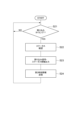
- Control procedure As an example of the control method, a control procedure including a communication procedure by the communication system 1 will be illustrated in detail. In the following, this control procedure is divided into a local time synchronization procedure performed by the local controller 300, a host control procedure performed by the controller 100, and a local control procedure performed by the local controller 300, and illustrated in detail.
- step S31 the local time generator 311 confirms whether or not the interrupt output unit 417 has output an interrupt signal. If it is determined in step S31 that the interrupt signal has not been output, the local controller 300 executes step S32. In step S32, the local time generator 311 confirms whether or not the time information transmitted from the time transmitter 424 has been received. If it is determined in step S32 that the time information has not been received, the local controller 300 returns the process to step S31.
- step S33 the local time generator 311 corrects the local time based on the interrupt signal. For example, the local time generator 311 corrects the local time so that the time at which the interrupt signal is scheduled to be output matches the time at which the interrupt signal is actually detected.
- step S34 the local time is corrected so that the time at which the interrupt signal is scheduled to be output matches the second time represented by the time information.
- the local controller 300 After steps S33 and S34, the local controller 300 returns the process to step S31.
- the local controller 300 repeatedly executes the above procedure. After the local time is synchronized with the second time in steps S33 and S34, the synchronization of the local time with the second time can be maintained simply by repeating step S33. Therefore, it is not essential for the second communication device 400 to transmit the time information each time it outputs an interrupt signal.
- step S41 the reading unit 114 confirms whether or not the host time is a multiple of the host control period.
- step S42 the reception data acquisition unit 112 acquires the feedback data set from the reception buffer 214, and converts the feedback timing information into the cycle number of the host control period from the current time to the feedback timing.
- Received data acquisition section 112 causes standby buffer 113 to store a feedback data set including the feedback timing information converted into the number of cycles. After that, the controller 100 returns the process to step S41.
- step S41 When it is determined in step S41 that the host time is a multiple of the host control period, the controller 100 executes steps S43, S44, S45, S46, and S47.
- step S ⁇ b>43 the reading unit 114 counts down feedback timing information in all feedback data sets stored in the standby buffer 113 .
- step S44 the reading unit 114 reads from the standby buffer 113 the feedback data set whose feedback timing information is zero.
- the control calculation section 115 based on the feedback data set read by the reading section 114 , the control calculation section 115 generates a command data set.
- step S46 the control calculation unit 115 adds command timing information to the generated command data set.
- step S ⁇ b>47 the control calculation unit 115 stores the command data set to which the command timing information is added in the transmission buffer 212 .
- the command data set stored in transmission buffer 212 is transmitted to wireless communication section 413 by wireless communication section 213 .
- step S47 the controller 100 returns the process to step S41. The controller 100 repeatedly executes the above procedure.
- step S51 the reading unit 314 confirms whether or not the local time is a multiple of the local control cycle.
- step S51 If it is determined in step S51 that the local time is not a multiple of the local control period, the local controller 300 executes step S52.
- step S52 the reception data acquisition unit 312 acquires the command data set from the reception buffer 414 and converts the command timing information into the number of cycles of the local control cycle from the current time to the command timing.
- the reception data acquisition unit 312 causes the standby buffer 313 to store the command data set including the command timing information converted into the number of cycles. After that, the local controller 300 returns the process to step S51.
- step S51 When it is determined in step S51 that the local time is a multiple of the local control period, the local controller 300 executes steps S53, S54, S55, S56, and S57.
- step S ⁇ b>53 the reading unit 314 counts down the command timing information in all command data sets stored in the standby buffer 313 .
- step S54 the reading unit 314 reads from the standby buffer 313 the command data set whose command timing information is zero.
- the control unit 315 controls the machine 30 based on the command data set read by the reading unit 314 and acquires the feedback data set from the machine 30 .
- step S56 the control unit 315 adds feedback timing information to the acquired feedback data set.
- step S ⁇ b>57 the control unit 315 stores the feedback data set to which the feedback timing information is added in the transmission buffer 412 .
- the feedback data set stored in transmission buffer 412 is transmitted to wireless communication section 213 by wireless communication section 413 .
- step S57 the local controller 300 returns the process to step S51. The local controller 300 repeats the above procedure.
- the communication system 1 is a system that performs wireless communication between a first application and a second application, and includes the first communication device 200 that performs first wired communication with the first application; and a second communication device 400 that performs second wired communication with the second application and wireless communication with the first communication device 200, and the first communication device 200 acquires the first time from the first application.
- the second communication device 400 includes an acquisition unit 215, and includes a second time generation unit 416 that generates a second time synchronized with the first time, and an interrupt signal that is synchronized with the second time and periodically sent to the second application. and an interrupt output unit 417 for outputting.
- this communication system even in the second application that does not have the function of performing communication that guarantees time synchronization with the second communication device 400, based on the interrupt signal, it is acquired from the first application It is possible to perform processing synchronized with the first time. Therefore, it is effective for easily synchronizing applications communicating with each other.
- the second communication device 400 may further include a status output unit 423 that outputs synchronization status information representing the synchronization state of the second time with respect to the first time to the second application. Based on the synchronization status information, the reliability of synchronization between applications can be improved.
- the first time acquisition unit 215 further acquires timing information representing the relationship between the first time and the output timing of the interrupt signal from the first application
- the interrupt output unit 417 acquires the relationship between the second time and the output timing. may output an interrupt signal to the second application so that the relationship represented by the timing information is established.
- the output timing of the interrupt signal can be easily adjusted.
- the second communication device 400 may further include a time transmission unit 424 that transmits time information representing the second time to the second application. Even in the second application that does not have a function to perform communication that guarantees time synchronization with the second communication device 400, the time synchronized with the second time is corrected by correcting the second time based on the interrupt signal. can be generated.
- the second communication device 400 further includes a time synchronization unit 425 that generates the second application time synchronized with the second time in the second application based on the communication delay time between the second communication device 400 and the second application. may have. It can also be applied to a second application having a function of performing communication with the second communication device 400 to ensure time synchronization.
- the second communication device 400 transmits the communication packet acquired from the first communication device 200 by wireless communication to the second application through the communication line, and the interrupt output unit 417 outputs an interrupt signal through an interrupt line provided separately from the communication line. may be output to the second application. An interrupt signal can be timely output to the second application.
- the second communication device 400 transmits the communication packet acquired from the first communication device 200 by wireless communication to the second application via the communication line, and the interrupt output unit 417 transmits the interrupt packet including the interrupt signal to the second application via the communication line. may be sent to The interrupt signal can be output to the second application without providing an interrupt line separate from the communication line.
- the interrupt output unit 417 may give priority to interrupt packets over communication packets and transmit them to the second application. In the configuration in which the interrupt signal is output by the transmission of the interrupt packet, the interrupt signal can be output to the second application in a more timely manner.
- the first communication device 200 and the second communication device 400 may further have a reference time generation unit 211 that generates the communication reference time, and perform wireless communication based on the communication reference time.
- the timing of wireless communication can be appropriately adjusted independently of the first time and the second time.
- the first communication device 200 and the second communication device 400 perform mobile communication, the first communication device 200 is a base station for mobile communication, and the second communication device 400 is a mobile station for mobile communication. good too.
- the versatility of synchronous communication can be further improved.
- the first communication device 200 and the second communication device 400 may perform local mobile communication synchronized with public mobile communication performed by a public base station different from the first communication device 200 based on the communication reference time. .
- the reliability of wireless communication performed by the first communication device 200 and the second communication device 400 can be improved.
- a controller that performs first wired communication with a first communication device 200 as a first application, and a second application that performs second wired communication with a second communication device 400, and a local device based on command data transmitted from the controller by wireless communication.
- the local controller may control the local device at timing based on the interrupt signal.
- the interrupt signal can be effectively used for synchronous communication of command data between the controller and the local controller.
- the second communication device 400 further has a time transmission unit 424 that transmits time information representing the second time to the second application, and the local controller synchronizes with the second time based on the time information and the interrupt signal.
- local time may be generated and the local device may be controlled at timing based on the local time.
- the local device can be controlled in synchronization with the second time in a control cycle shorter than the output cycle of the interrupt signal.
- the second communication device 400 performs wireless communication between the first application and the first communication device 200 (counterparty device) that performs the first wired communication, and transmits information acquired from the first communication device 200 by wireless communication to the second communication device.
- a second time generating unit 416 which is a device for transmitting to a second application by wired communication and generates a second time synchronized with the first time acquired by the first communication device 200 from the first application; and an interrupt output unit 417 that periodically outputs a synchronous interrupt signal to the second application.
- Reference Signs List 1 communication system 200 first communication device 211 reference time generation unit 215 first time acquisition unit 400 second communication device 416 second time generation unit 417 interrupt output unit 423 status output unit, 424... time transmission unit, 425... time synchronization unit.
Landscapes
- Engineering & Computer Science (AREA)
- Computer Networks & Wireless Communication (AREA)
- Signal Processing (AREA)
- Multimedia (AREA)
- Computer Hardware Design (AREA)
- Synchronisation In Digital Transmission Systems (AREA)
Priority Applications (4)
| Application Number | Priority Date | Filing Date | Title |
|---|---|---|---|
| JP2023578329A JP7639187B2 (ja) | 2022-02-07 | 2022-02-07 | 通信システム、通信装置、及び通信方法 |
| CN202280090890.2A CN118648262A (zh) | 2022-02-07 | 2022-02-07 | 通信系统、通信装置以及通信方法 |
| PCT/JP2022/004621 WO2023148956A1 (ja) | 2022-02-07 | 2022-02-07 | 通信システム、通信装置、及び通信方法 |
| EP22924866.1A EP4456473A4 (en) | 2022-02-07 | 2022-02-07 | COMMUNICATION SYSTEM, COMMUNICATION DEVICE AND COMMUNICATION METHOD |
Applications Claiming Priority (1)
| Application Number | Priority Date | Filing Date | Title |
|---|---|---|---|
| PCT/JP2022/004621 WO2023148956A1 (ja) | 2022-02-07 | 2022-02-07 | 通信システム、通信装置、及び通信方法 |
Publications (1)
| Publication Number | Publication Date |
|---|---|
| WO2023148956A1 true WO2023148956A1 (ja) | 2023-08-10 |
Family
ID=87551994
Family Applications (1)
| Application Number | Title | Priority Date | Filing Date |
|---|---|---|---|
| PCT/JP2022/004621 Ceased WO2023148956A1 (ja) | 2022-02-07 | 2022-02-07 | 通信システム、通信装置、及び通信方法 |
Country Status (4)
| Country | Link |
|---|---|
| EP (1) | EP4456473A4 (https=) |
| JP (1) | JP7639187B2 (https=) |
| CN (1) | CN118648262A (https=) |
| WO (1) | WO2023148956A1 (https=) |
Citations (4)
| Publication number | Priority date | Publication date | Assignee | Title |
|---|---|---|---|---|
| JPH03107790A (ja) * | 1989-09-21 | 1991-05-08 | Toshiba Corp | 遠方監視制御装置 |
| JPH06303684A (ja) * | 1993-04-15 | 1994-10-28 | Toshiba Corp | 遠方監視制御装置 |
| JPH0898263A (ja) * | 1994-09-21 | 1996-04-12 | Mitsubishi Electric Corp | 遠方監視制御装置および時刻同期装置 |
| WO2020230824A1 (ja) * | 2019-05-13 | 2020-11-19 | 株式会社安川電機 | マシン制御システム、プログラム、マシン、及び通信方法 |
Family Cites Families (1)
| Publication number | Priority date | Publication date | Assignee | Title |
|---|---|---|---|---|
| US12464041B2 (en) * | 2019-02-13 | 2025-11-04 | Telefonaktiebolaget Lm Ericsson (Publ) | Industrial automation with 5G and beyond |
-
2022
- 2022-02-07 EP EP22924866.1A patent/EP4456473A4/en active Pending
- 2022-02-07 CN CN202280090890.2A patent/CN118648262A/zh active Pending
- 2022-02-07 JP JP2023578329A patent/JP7639187B2/ja active Active
- 2022-02-07 WO PCT/JP2022/004621 patent/WO2023148956A1/ja not_active Ceased
Patent Citations (5)
| Publication number | Priority date | Publication date | Assignee | Title |
|---|---|---|---|---|
| JPH03107790A (ja) * | 1989-09-21 | 1991-05-08 | Toshiba Corp | 遠方監視制御装置 |
| JPH06303684A (ja) * | 1993-04-15 | 1994-10-28 | Toshiba Corp | 遠方監視制御装置 |
| JPH0898263A (ja) * | 1994-09-21 | 1996-04-12 | Mitsubishi Electric Corp | 遠方監視制御装置および時刻同期装置 |
| WO2020230824A1 (ja) * | 2019-05-13 | 2020-11-19 | 株式会社安川電機 | マシン制御システム、プログラム、マシン、及び通信方法 |
| JP6916399B2 (ja) | 2019-05-13 | 2021-08-11 | 株式会社安川電機 | マシン制御システム、プログラム、マシン、及び通信方法 |
Non-Patent Citations (1)
| Title |
|---|
| See also references of EP4456473A4 |
Also Published As
| Publication number | Publication date |
|---|---|
| JP7639187B2 (ja) | 2025-03-04 |
| JPWO2023148956A1 (https=) | 2023-08-10 |
| CN118648262A (zh) | 2024-09-13 |
| EP4456473A1 (en) | 2024-10-30 |
| EP4456473A4 (en) | 2025-07-09 |
Similar Documents
| Publication | Publication Date | Title |
|---|---|---|
| JP5430793B2 (ja) | 電動機制御システムおよび通信方法 | |
| WO2022230280A1 (ja) | ロボット制御システム、ロボット制御方法及びプログラム | |
| JP2013066962A (ja) | ロボット制御装置、及びロボットシステム | |
| WO2020230824A1 (ja) | マシン制御システム、プログラム、マシン、及び通信方法 | |
| WO2016129294A1 (ja) | 通信制御システム及び通信制御方法 | |
| WO2023148956A1 (ja) | 通信システム、通信装置、及び通信方法 | |
| JP4980292B2 (ja) | 異なる通信周期で複数のアンプと通信する数値制御システム | |
| JP7650977B2 (ja) | 通信システム、コントロールシステム、及び通信方法 | |
| WO2021033358A1 (ja) | 制御システム、制御装置およびプログラム | |
| WO2024185100A1 (ja) | 制御システム、通信端末、及び通信方法 | |
| JP7663702B2 (ja) | 通信システム、通信制御回路及び通信方法 | |
| US12138791B2 (en) | Robot control system, lower-level control apparatus, and control method for robot | |
| JP6629817B2 (ja) | 制御システム、および、モータ制御方法 | |
| US20240243894A1 (en) | Wireless communication of transmission data by attribute | |
| JPH07200010A (ja) | プログラマブルコントローラおよびその排他制御交信方法 | |
| WO2023058116A1 (ja) | 通信システム及び通信方法 | |
| WO2023058120A1 (ja) | 無線通信装置及び通信方法 | |
| EP4318153B1 (en) | Industrial system, industrial machine, and control method | |
| WO2025179556A1 (en) | Method and mobile device of teaching industrial robot | |
| JP2004025428A (ja) | ロボット制御装置の通信方法およびロボット制御装置 | |
| JP7635059B2 (ja) | サーボシステム | |
| JPWO2023281805A5 (https=) | ||
| EP4486006A1 (en) | Communication system and communication terminal | |
| JP2013066963A (ja) | ロボット制御装置、及びロボットシステム | |
| JP4605043B2 (ja) | 通信処理方法 |
Legal Events
| Date | Code | Title | Description |
|---|---|---|---|
| 121 | Ep: the epo has been informed by wipo that ep was designated in this application |
Ref document number: 22924866 Country of ref document: EP Kind code of ref document: A1 |
|
| ENP | Entry into the national phase |
Ref document number: 2023578329 Country of ref document: JP Kind code of ref document: A |
|
| ENP | Entry into the national phase |
Ref document number: 2022924866 Country of ref document: EP Effective date: 20240723 |
|
| WWE | Wipo information: entry into national phase |
Ref document number: 202280090890.2 Country of ref document: CN |
|
| NENP | Non-entry into the national phase |
Ref country code: DE |