WO2023135657A1 - ろ過装置 - Google Patents
ろ過装置 Download PDFInfo
- Publication number
- WO2023135657A1 WO2023135657A1 PCT/JP2022/000605 JP2022000605W WO2023135657A1 WO 2023135657 A1 WO2023135657 A1 WO 2023135657A1 JP 2022000605 W JP2022000605 W JP 2022000605W WO 2023135657 A1 WO2023135657 A1 WO 2023135657A1
- Authority
- WO
- WIPO (PCT)
- Prior art keywords
- electrode
- particles
- potential
- filter medium
- filter
- Prior art date
- Legal status (The legal status is an assumption and is not a legal conclusion. Google has not performed a legal analysis and makes no representation as to the accuracy of the status listed.)
- Ceased
Links
Images


Classifications
-
- B—PERFORMING OPERATIONS; TRANSPORTING
- B01—PHYSICAL OR CHEMICAL PROCESSES OR APPARATUS IN GENERAL
- B01D—SEPARATION
- B01D35/00—Filtering devices having features not specifically covered by groups B01D24/00 - B01D33/00, or for applications not specifically covered by groups B01D24/00 - B01D33/00; Auxiliary devices for filtration; Filter housing constructions
- B01D35/06—Filters making use of electricity or magnetism
-
- B—PERFORMING OPERATIONS; TRANSPORTING
- B01—PHYSICAL OR CHEMICAL PROCESSES OR APPARATUS IN GENERAL
- B01D—SEPARATION
- B01D61/00—Processes of separation using semi-permeable membranes, e.g. dialysis, osmosis or ultrafiltration; Apparatus, accessories or auxiliary operations specially adapted therefor
- B01D61/14—Ultrafiltration; Microfiltration
- B01D61/149—Multistep processes comprising different kinds of membrane processes selected from ultrafiltration or microfiltration
-
- B—PERFORMING OPERATIONS; TRANSPORTING
- B01—PHYSICAL OR CHEMICAL PROCESSES OR APPARATUS IN GENERAL
- B01D—SEPARATION
- B01D61/00—Processes of separation using semi-permeable membranes, e.g. dialysis, osmosis or ultrafiltration; Apparatus, accessories or auxiliary operations specially adapted therefor
- B01D61/42—Electrodialysis; Electro-osmosis ; Electro-ultrafiltration; Membrane capacitive deionization
- B01D61/425—Electro-ultrafiltration
- B01D61/4251—Electro-ultrafiltration comprising multiple electro-ultrafiltration steps
Definitions
- the present disclosure relates to filtering devices.
- a compression-type filtration device has been used as a filtration device for filtering slurry.
- a filter medium such as a filter cloth is installed at the bottom of the container.
- a slurry is deposited on the filter media.
- a pressure plate is arranged above the slurry. When the pressing plate descends, the slurry is pressed against the filter media. The liquid contained in the slurry passes through the filter media and is discharged to the outside of the container. On the other hand, the solids do not pass through the filter medium and a dewatered cake is produced on the filter medium.
- the particles contained in the slurry block the filter media, causing clogging of the filter media. Therefore, the filtration speed is lowered, and the time required for the filtration process is long.
- an object of the present disclosure is to provide a filtering device that shortens the time required for filtering.
- a filtering device includes a first electrode provided with a plurality of first openings and a plurality of second openings provided facing one surface of the first electrode. Two electrodes, a plurality of openings are provided, a filter medium provided between the first electrode and the second electrode, and particles to be separated provided in contact with the other surface of the first electrode and a third electrode facing the first electrode with the filter chamber interposed therebetween.
- the first electrode and the second electrode or the third electrode sandwiching the filter medium are movable in the facing direction in which the first electrode and the third electrode face each other.
- the time required for filtration processing is shortened.
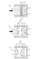
- FIG. 1 is a cross-sectional view schematically showing a configuration example of a filtering device according to Embodiment 1.
- FIG. FIG. 2 is a cross-sectional view showing the filtration (during compression) of the filtering device according to Embodiment 1.
- FIG. 3 is an explanatory diagram for explaining the operation of the filtering device according to Embodiment 1.
- FIG. 4 is a cross-sectional view schematically showing the configuration of the first electrode, filter medium, and second electrode.
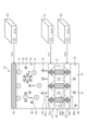
- 5 is an electrical equivalent circuit diagram showing the filtering device according to Embodiment 1.
- FIG. FIG. 6 is a flowchart showing how the filtering device according to Embodiment 1 is used.
- FIG. 7 is a cross-sectional view schematically showing a configuration example of a filtering device according to Embodiment 2.
- FIG. 8 is an explanatory diagram for explaining the operation of the filtering device according to Embodiment 2.
- FIG. 9 is an electrical equivalent circuit diagram showing a filtering device according to Embodiment 2.
- FIG. 1 is a cross-sectional view schematically showing a configuration example of a filtering device according to Embodiment 1.
- FIG. The filtration device 10 according to the first embodiment is a device that separates particles 71 from a slurry (undiluted solution) 70 (target treatment liquid) in which particles (particles to be separated) 71 are dispersed in a polar solvent 72 .
- the filter device 10 can be applied to the fields of life science, sewage treatment, wastewater treatment, and the like.
- life science the bio industry that cultures microorganisms such as cultured cells, microalgae, bacteria, bacteria, viruses, etc., and the use and application of enzymes, proteins, polysaccharides, lipids, etc.
- the filtration device 10 is a colloidal fine particle-based slurry in which surface-charged fine particles are highly dispersed by electrical repulsion, and can be applied to concentration and recovery of colloidal fine particles.
- the filtering device 10 includes an upper housing 11, a lid portion 12, a side housing 13, a lower housing 14, a conductor 15, and a cylinder (not shown). and have The filtration device 10 includes a first filter chamber 30, a first electrode 31, a second electrode 32, and a third electrode in an internal space surrounded by an upper housing 11, a side housing 13, and a lower housing 14. 33 and a filter medium 34 (see FIG. 3).
- a first power source 51 and a second power source 52 are electrically connected to the filtering device 10 .
- the direction in which the first electrode 31, the second electrode 32, the third electrode 33, and the filter medium 34 are arranged is the vertical direction.
- the upper housing 11 is a cylindrical member made of an insulating material.
- the side housing 13 is an annular member made of an insulating material and having a through hole 13a. A lower end portion of the upper housing 11 is inserted into the through hole 13 a of the side housing 13 . Also, the lower end of the upper housing 11 is slidably fitted to the inner peripheral surface of the through hole 13a. Therefore, the upper housing 11 is vertically slidable with respect to the side housings 13 .
- the lid portion 12 is arranged above the upper housing 11 and integrated with the upper housing 11 .
- a connecting portion 60 that connects with a shaft portion of a cylinder (not shown) is connected to the upper portion of the lid portion 12 .
- cylinders include air cylinders and hydraulic cylinders. Therefore, when the cylinder is driven, the lid portion 12 and the side housing 13 move up and down via the connecting portion 60 . Thereby, the volume of the first filter chamber 30 changes.
- the lower housing 14 is made of an insulating material and supports the side housing 13 .
- the lid portion 12 is provided to cover the upper surface of the upper housing 11 . Note that although the embodiment includes the cylinder and the connecting portion 60 , the present disclosure does not necessarily include the cylinder and the connecting portion 60 . In such a case, it is necessary for the operator to move the upper housing 11 vertically.
- the outer edges of the first electrode 31, the second electrode 32, and the filter material 34 are sandwiched between the side housing 13 and the lower housing 14 and fixed.
- the third electrode 33 is arranged inside the through hole of the side housing 13 . Further, the third electrode 33 is fixed to the lower surface of the upper housing 11 (the surface facing the lower housing 14) with fasteners such as bolts. Therefore, when the upper housing 11 moves up and down by driving the cylinder, the third electrode 33 also moves up and down.
- the facing direction in which the first electrode 31 and the third electrode 33 face each other is the vertical direction.
- the conductor 15 is an annular member provided so as to surround the side housing 13 and is provided between the side housing 13 and the lower housing 14 . A lower end side of the conductor 15 is connected to the outer edge of the first electrode 31 .
- the upper housing 11 and the conductor 15 are annular members, they are not limited to this, and may be polygonal or other shapes.
- the upper housing 11 and the side housing 13 are connected so as to be freely slidable (movable) in the vertical direction by a guide portion 21a. As a result, the upper housing 11 is supported by the side housings 13 without rattling in the planar direction perpendicular to the guide portion 21a.
- the side housing 13, the lower housing 14, and the conductor 15 are fixed by bolts 21b and 21c. As a result, the positions of the housings are fixed, and the space surrounded by the first electrode 31, the second electrode 32, the filter medium 34, the inner wall of the side housing 13, and the third electrode 33 is filled with the first filter chamber. 30 are formed.
- a sealing member such as an O-ring is provided at each connecting portion between the housings and between the electrodes, so that the first filter chamber 30 is provided in a sealed manner. Further, the distance between the upper housing 11 and the lower housing 14 is adjusted by driving the cylinder. As a result, the filtering device 10 can appropriately set the volume of the first filter chamber 30 according to the type and amount of the slurry (raw liquid) 70 (hereinafter sometimes referred to as the target treatment liquid).
- the upper housing 11 is provided with a slurry supply passage 11a, an exhaust passage 11b, and a through hole 11c.
- One end side of the slurry supply passage 11 a opens to the side surface of the upper housing 11 and is connected to the slurry supply section 16 .
- the other end side of the slurry supply passage 11 a is opened to the lower surface of the upper housing 11 and connected to the through hole 33 a of the third electrode 33 .
- the slurry supply valve 17 has a rod-shaped member 17a provided inside the slurry supply passage 11a, and the rod-shaped member 17a moves up and down in the slurry supply passage 11a to switch the open/closed state of the through hole 33a. can be done.
- the slurry (undiluted solution) 70 flows through the slurry supply section 16, the slurry supply passage 11a, and the through-hole 33a of the third electrode 33. It is supplied to the first filter chamber 30 . Further, when the through hole 33a is closed by the slurry supply valve 17, the supply of the slurry (undiluted solution) 70 to the first filter chamber 30 is stopped.
- the air discharge valve 19 has a rod-shaped member 19a provided inside the exhaust passage 11b. , the open/closed state of the through hole 33b can be switched.
- the slurry supply valve 17 and the air discharge valve 19 are fixed to the lid portion 12 . Therefore, when the cylinder is driven, the slurry supply valve 17 and the air discharge valve 19 move up and down together with the lid portion 12 and the side housing 13 .
- the air discharge valve 19 opens the through hole 33b.
- the air in the first filter chamber 30 is exhausted to the outside through the through hole 33b, the exhaust passage 11b, and the air exhaust portion 18.
- An air discharge valve 18 a is connected to the air discharge portion 18 .
- the air discharge valve 18a is, for example, a float valve, and is provided so that the air discharge valve 18a is closed when a predetermined amount of air in the first filter chamber 30 is discharged. After the first filter chamber 30 is completely exhausted, the air discharge valve 19 closes the through hole 33b.
- the third electrode 33 is electrically connected to the reference potential GND via the connection conductor 56 .
- the reference potential GND is, for example, the ground potential. However, the reference potential GND is not limited to this, and may be a predetermined fixed potential different from the ground potential.
- the first electrode 31 is electrically connected to the second terminal 51b of the first power supply 51 via the conductor 15 and the connection conductor 54. Also, the first electrode 31 is electrically connected to the first terminal 52a of the second power supply 52 via the conductor 15 and the connection conductor 55a.
- the lower housing 14 is provided with a concave second filter chamber 35, through holes 14a and 14b, and a connection hole 14c.
- the second filter chamber 35 is provided at a position overlapping the first filter chamber 30 on the upper surface of the lower housing 14 .
- the through hole 14 a connects the second filter chamber 35 and the discharge portion 22 .
- Particles 71 are separated from the slurry (undiluted solution) 70 supplied to the first filter chamber 30 by driving each electrode, and the polar solvent 72 (filtrate 75) from which the particles 71 are separated is transferred to the first electrode 31 and the filter medium 34. (see FIG. 3) and the second electrode 32 to flow into the second filter chamber 35 .
- Filtrate 75 containing polar solvent 72 from which particles 71 have been separated is collected in an external storage tank from outlet 22 of second filter chamber 35 through through hole 14b.
- connection hole 14c One end side of the connection hole 14c opens to the upper surface of the lower housing 14, and the outer edge of the second electrode 32 is provided to cover the opening 14d of the connection hole 14c. Further, the other end side of the connection hole 14 c opens to the side surface of the lower housing 14 .
- a connection conductor 55b is inserted into the connection hole 14c, and the connection conductor 55b and the second electrode 32 are connected. Thereby, the second electrode 32 is electrically connected to the second terminal 52 b of the second power supply 52 .
- the configuration of the filtering device 10 shown in FIG. 1 is merely an example, and the first filter chamber sandwiched between the first electrode 31, the second electrode 32, the filter medium 34 (see FIG. 3), and the third electrode 33 Any configuration can be used as long as 30 can be formed.
- the first electrode 31, the second electrode 32, and the third electrode 33 are made of, for example, a titanium alloy or an alumite-treated aluminum alloy, but are not limited to these.
- FIG. 2 is a cross-sectional view showing the filtration (during compression) of the filtration device according to Embodiment 1.
- FIG. 2 The filtering process of the filtering device 10 described above will be briefly described. 2, the through holes 33a and 33b of the third electrode 33 are closed by inserting the rod-shaped members 17a and 19a.
- a cylinder (not shown) is driven to move the lid portion 12 and the side housing 13 downward (see arrow X). That is, the third electrode 33 presses downward the slurry 70 supplied to the first filter chamber 30 . Thereby, the slurry 70 is pressed (squeezed) against the first electrode 31 , the second electrode 32 and the filter medium 34 .
- the liquid contained in the slurry 70 passes through the filter medium 34 to move to the second filter chamber 35 and is discharged from the discharge portion 22 .
- particles having a particle size larger than the mesh openings 34b (see FIG. 3) of the filter medium 34 cannot pass through the filter medium 34 and are deposited on the filter medium 34 as a dehydrated cake 80.
- pressing the slurry 70 against the first electrode 31, the second electrode 32 and the filter medium 34 by the third electrode 33 may be simply referred to as "squeezing".
- the filter device 10 of Embodiment 1 uses the first power source 51 and the second power source 52 for the first electrode 31, the second electrode 32, and the third electrode 33. It is squeezed while supplying a predetermined potential from and. Details of the filtering device 10 will be described below with reference to FIGS. 3 to 5 .
- FIG. 3 is an explanatory diagram for explaining the operation of the filtering device according to Embodiment 1.
- FIG. 3 in order to make the explanation easier to understand, the arrangement relationship between the first electrode 31, the second electrode 32, the third electrode 33, the filter medium 34, and the first filter chamber 30 and the second filter chamber 35 is schematically shown. showing.
- the first electrode 31 and the second electrode 32 are mesh electrodes having openings, for example.
- the first electrode 31 has a plurality of thin conductive wires 31a, and a plurality of first openings 31b are provided between the thin conductive wires 31a.
- the second electrode 32 has a plurality of thin conductive wires 32a, and a plurality of second openings 32b are provided between the thin conductive wires 32a.
- the second electrode 32 is provided to face one surface (lower surface) of the first electrode 31 with the filter medium 34 interposed therebetween.
- the filter material 34 is provided between the first electrode 31 and the second electrode 32 .
- the first electrode 31 and the second electrode 32 are provided in direct contact with the filter medium 34 .
- the plurality of thin conductive wires 31a and the plurality of thin conductive wires 32a may be metal or carbon fiber.
- the first electrode 31 and the second electrode 32 are not limited to being in direct contact with the filter medium 34, and may be arranged with a gap between them.
- the filter medium 34 is formed by providing a plurality of openings 34b in a filtration membrane 34a.
- a microfiltration membrane Microfiltration Membrane
- UF membrane Ultrafiltration Membrane
- the filter medium 34 is made of an insulating material such as a resin material.
- the first opening 31b of the first electrode 31, the second opening 32b of the second electrode 32, and the opening 34b of the filter medium 34 are shown to have the same size. The sizes of the first opening 31b, the second opening 32b and the opening 34b may be different.
- FIG. 4 is a cross-sectional view schematically showing the configuration of the first electrode, filter medium and second electrode.
- the diameter D3 of the opening 34b provided in the filter medium 34 is smaller than the diameter D1 of the first opening 31b of the first electrode 31 and the diameter of the second opening 32b of the second electrode 32. smaller than D2.
- the arrangement pitch of the plurality of conductive fine wires 31a, the arrangement pitch of the plurality of conductive fine wires 32a, and the arrangement pitch of the filtration membranes 34a are provided mutually different.
- the diameter D1 of the first opening 31b of the first electrode 31 is 0.5 ⁇ m or more and 500 ⁇ m or less, for example, about 70 ⁇ m.
- a diameter D2 of the second opening 32b of the second electrode 32 is 0.5 ⁇ m or more and 1000 ⁇ m or less, for example, about 100 ⁇ m.
- a diameter D3 of the plurality of openings 34b provided in the filter medium 34 is approximately 0.1 ⁇ m to 100 ⁇ m, more preferably approximately 1 ⁇ m to 7 ⁇ m.
- the diameter D1 of the first opening 31b of the first electrode 31 is smaller than the diameter D2 of the second opening 32b of the second electrode 32.
- the diameter D1 of the first opening 31b of the first electrode 31 may be formed to have the same size as the diameter D2 of the second opening 32b of the second electrode 32 .
- the openings 34b of the filter material 34 are provided so as not to overlap the plurality of thin conductive wires 31a and the plurality of thin conductive wires 32a at least in the regions overlapping the first openings 31b and the second openings 32b.
- the distance between the first electrode 31 and the second electrode 32 is defined by the thickness of the filter medium 34 .
- the third electrode 33 is a plate-like member and provided to face the other surface (upper surface) of the first electrode 31 with the first filter chamber 30 interposed therebetween. 3, the through holes 33a and 33b and the recess 33c (see FIG. 1) of the third electrode 33 are omitted.
- the first filter chamber 30 is provided in contact with the other surface (upper surface) of the first electrode 31 .
- the first filter chamber 30 is supplied with the slurry (undiluted solution) 70 containing the particles 71 to be separated and the polar solvent 72 .
- the particles 71 are, for example, biomass fine particles or colloidal fine particles, and the surfaces of the particles are negatively charged.
- the particles 71 are chlorella, microalgae spirulina, colloidal silica, Escherichia coli, activated sewage sludge, or the like.
- the diameter of the particles 71 varies depending on the technical field to which it is applied and the type of separation object, but is approximately 5 nm or more and 2000 ⁇ m or less, for example, approximately 20 nm or more and 500 ⁇ m or less.
- the polar solvent 72 in which the particles 71 are dispersed is water, and the water molecules 73 are positively charged. As a result, the slurry (undiluted solution) 70 as a whole is in an electrically balanced state.
- the polar solvent 72 is not limited to water, and may be, for example, alcohol. That is, the polar solvent 72 should just be a polar solvent.
- the first power supply 51 supplies the first electrode 31 with the first potential V1 having the same polarity as the particles 71 .
- the first potential V1 is -60V, for example.
- the second power supply 52 supplies the second electrode 32 with a second potential V2 having the same polarity as that of the particles 71 and a larger absolute value than the first potential V1.
- the second potential V2 is -70V, for example.
- the third electrode 33 is connected to the reference potential GND.
- the reference potential GND is the ground potential as described above, ideally 0V. Note that the reference potential GND supplied to the third electrode 33 is not limited to 0V, and may be a predetermined fixed potential.
- the absolute values of the first potential V1 and the second potential V2 can be set within a range of 1 mV or more and 1000 V or less.
- FIG. 5 is an electrical equivalent circuit diagram showing the filtering device according to Embodiment 1.
- the first power source 51 is a constant voltage source and the second power source 52 is a constant current source.
- a resistance component R1 and a capacitance component C are connected in parallel between the first electrode 31 and the second electrode 32 .
- the resistance component R1 and the capacitance component C are equivalently represented by the filter medium 34 provided with a large number of openings 34b.
- a resistance component R2 is connected between the first electrode 31 and the third electrode 33 .
- the resistance component R2 is equivalently represented by the slurry (undiluted solution) 70 in the first filter chamber 30 .
- the second power supply 52 may be a constant voltage power supply or a constant current power supply.
- the second power supply 52 is a constant current source, so depending on the filtering state of the filter device 10, that is, the resistance component R1 of the filter medium 34 and the resistance component R2 of the first filter chamber 30 change , the second potential V2 changes.
- the second potential V2 has the same polarity as the particle 71 and maintains a value greater than the absolute value of the first potential V1.
- each electrode (31, 32, 33) during filtration (during compression) of the filtering device 10 will be described.
- a repulsive force F1 is generated between the negatively charged particles 71 and the first electrode 31 when the filtering device 10 is squeezed. That is, the negatively charged particles 71 move away from the first electrode 31 and approach the third electrode 33 due to the repulsive force F ⁇ b>1 generated between them and the first electrode 31 .
- the filter device 10 when the filter device 10 is squeezed, the slurry 70 itself is pressed against the first electrode 31 and the filter medium 34, but the particles 71 are distributed toward the third electrode 33 inside the slurry 70. Therefore, clogging of the openings 34b of the filter medium 34 with the particles 71 is suppressed. Also, as the water contained in the slurry 70 decreases due to the compression, the distance between the first electrode 31 and the particles 71 becomes smaller. Then, toward the end of squeezing, the particles 71 come into contact with the filter medium 34 . Ultimately, particles 71 contained in slurry 70 are layered on first electrode 31 and filter media 34 to form dewatered cake 80 .
- an attractive force is generated between the positively charged water molecules 73 and the first electrode 31 .
- the attractive force F ⁇ b>2 acting on the positively charged water molecules 73 acts in the direction indicated by the arrow, that is, in the direction from the third electrode 33 toward the first electrode 31 .
- the positively charged water molecules 73 move to the first electrode 31 side.
- the electric field E of the barrier from the first electrode 31 to the second electrode 32 (in FIG. , dashed line) are formed.
- the water molecules 73 that have moved to the first electrode 31 side receive force from the electric field E, are pulled toward the second electrode 32 side, and pass through the filter medium 34 .
- the surrounding water molecules 73 are also dragged toward the second electrode 32, generating an electroosmotic flow.
- the polar solvent 72 (filtrate 75 ) containing positively charged water molecules 73 flows into the second filter chamber 35 . Therefore, the amount of water discharged per unit time (the amount of water transferred to the second filter chamber 35) increases as compared to the case of simple filtration.
- the filtering device 10 of Embodiment 1 since the particles 71 do not come into contact with the filter medium 34 from the start of filtration to the end of the compression, the filtration resistance of the filter medium 34 does not increase. That is, the high filtration speed state (non-clogging state) of the filter medium 34 is maintained for a long time, and the time required for the filtration process is shortened. In addition, since the amount of water discharged per unit time (the amount of water transferred to the second filter chamber 35) is increased, the time required for the filtration process (compressing process) is further shortened. Also, the particles 71 receive a repulsive force from the first electrode 31 and are distributed toward the third electrode 33 . Therefore, filtration leakage (particles 71 passing through the openings 34b of the filter medium 34) is avoided.
- the electric field formed between the first electrode 31 and the second electrode 32 is controlled to control the particle level (particle diameter) passing through the filter medium 34. good too.
- a barrier is formed between the first electrode 31 and the second electrode 32. is formed (see FIG. 3), and particles 71 having a particle size smaller than the mesh opening 34b of the filter medium 34 can be suppressed from passing through the filter medium 34.
- FIG. That is, according to this embodiment, it is also possible to compress the nanoparticles.
- the particle size to be separated can be changed to the equivalent of an outer filtration membrane (UF membrane) or a nanofiltration membrane (NF membrane).
- An ultrafiltration membrane (UF membrane) is a filtration membrane with an opening diameter of approximately 10 nm or more and 100 nm or less.
- a nanofiltration membrane (NF membrane) is a filtration membrane having an opening diameter of about 1 nm or more and 10 nm or less.
- FIG. 6 is a flowchart showing how the filtering device according to Embodiment 1 is used.
- the slurry supply step S1 is performed first.
- the slurry supply step S ⁇ b>1 is a step of supplying the slurry 70 to the first filter chamber 30 of the filtration device 10 .
- the vertical position of the third electrode 33 is adjusted so that the third electrode 33 and the liquid surface of the slurry 70 are brought into contact with each other.
- a predetermined voltage is applied to the first electrode 31 , the second electrode 32 and the third electrode 33 .
- many particles 71 are distributed near the third electrode 33 and many water molecules 73 are distributed near the first electrode 31 in the first filter chamber 30 .
- the filtering process step S2 is performed.
- the filtration treatment step S2 is a step of continuously moving the third electrode 33 downward to apply filtration pressure to the slurry 70 .
- many water molecules 73 in the slurry 70 near the first electrode 31 pass through the filter medium 34 and move to the second filter chamber 35 .
- the filter medium 34 is not clogged. Therefore, the water molecules 73 smoothly pass through the filter medium 34 .
- the contact state between the third electrode 33 and the slurry 70 is maintained because the third electrode 33 is continuously moved downward. In other words, the state in which the particles 71 are distributed near the third electrode 33 and the water molecules 73 are distributed near the first electrode 31 is maintained. Therefore, a smooth filtration process is continuously performed, and the time for the filtration process is shortened.
- the pressing step S3 is a step of continuously moving the position of the third electrode 33 downward, like the filtering step S2.
- the slurry 70 is pressed (squeezed) against the first electrode 31 , the second electrode 32 and the filter medium 34 .
- Most of the water molecules 73 contained in the slurry 70 move to the second filter chamber 35 .
- the slurry 70 deposited on the filter media 34 becomes the dehydrated cake 80 .
- the time required for the pressing process is shortened.
- the downward movement of the third electrode 33 is stopped.
- voltage supply to the first electrode 31, the second electrode 32, and the third electrode 33 is stopped.
- the processing by the filtering device 10 ends.
- the configuration of the filtering device 10 described above is merely an example, and can be changed as appropriate.
- the negative filter plate formed by laminating the first electrode 31, the filter medium 34, and the second electrode 32 and the third electrode 33 are arranged to face each other in a parallel plate shape.
- the negative filter plate formed by stacking the first electrode 31, the filter medium 34 and the second electrode 32, and the third electrode 33 may each have a curved surface.
- the shape and arrangement of the negative filter plate and the third electrode 33 can be appropriately changed according to the shape and structure of the filtering device 10 .
- the concentration of the slurry (undiluted solution) 70 which is the target treatment liquid supplied to the first filter chamber 30, is not particularly limited, and can be changed according to the field to which the filtration device 10 is applied.
- first potential V1 and the second potential V2 are changed as appropriate according to the type of the particles 71 to be separated and the required filtration characteristics.
- the filtering device 10 of Embodiment 1 is provided with the first electrode 31 provided with the plurality of first openings 31b and the plurality of second openings 32b.
- a second electrode 32 provided opposite to and a plurality of openings 34b are provided, a filter medium 34 provided between the first electrode 31 and the second electrode 32, and the other surface of the first electrode 31
- a filter chamber (first filter chamber 30) provided in contact with and supplied with a slurry (raw solution) 70 (target treatment liquid) containing particles 71 to be separated and a polar solvent 72, and a first electrode sandwiching the filter medium 34 31 and the second electrode 32 or the third electrode 33 are movable in the facing direction (vertical direction) in which the first electrode 31 and the third electrode 33 face each other.
- the first potential V1 having the same polarity as the particles (particles 71) is supplied to the first electrode 31.
- FIG. The second electrode 32 is supplied with a second potential V2 having the same polarity as the particles (particles 71).
- a reference potential GND is supplied to the third electrode 33 .
- the absolute value of the second potential V2 is greater than the absolute value of the first potential V1.
- the first electrode 31 and the second electrode 32 or the third electrode 33 are moved to squeeze the slurry 70 deposited on the filter medium. Further, by supplying a predetermined potential to the first electrode 31, the second electrode 32, and the third electrode 33, a repulsive force generated between the first electrode 31 and the particles 71 acts. As a result, the particles 71 move away from the first electrode 31 due to the electrophoretic flow. As a result, an increase in the filtration resistance of the surface of the first electrode 31 and the filter medium 34 is suppressed, and the filtration processing time is shortened. In addition, the amount of water discharged per unit time (movement to the second filter chamber 35 amount) increases. This further shortens the filtering process time.
- the particles 71 are separated from the first electrode 31 by the repulsive force generated between the first electrode 31 and the particles 71, and filtration leakage is less likely to occur. Therefore, a polymer flocculant becomes unnecessary. Since the third electrode 33 is connected to the reference potential GND, the size of the filtering device 10 can be reduced compared to the case where the first electrode 31, the second electrode 32, and the third electrode 33 are each provided with a power source.
- the filtering device 10 also includes a cylinder (not shown) that moves the upper housing 11 vertically (opposing direction).
- the upper housing 11 is moved up and down by a cylinder (not shown).
- the second electrode 32 and the filter medium 34) may be vertically moved to compress.
- FIG. 7 is a cross-sectional view schematically showing a configuration example of a filtering device according to Embodiment 2.
- FIG. 8 is an explanatory diagram for explaining the operation of the filtering device according to Embodiment 2.
- FIG. The same reference numerals are given to the same components as those described in the above-described embodiment, and overlapping descriptions are omitted.
- the filtering device 10 includes an upper housing 11, a lid portion 12, a side housing 13, a lower housing 14, a conductor 15, and a cylinder (not shown). and have The filtration device 10 further includes a first filter chamber 30, a first electrode 31, a second electrode 32, and a second It has three electrodes 33 and a filter medium 34 (see FIG. 8).
- a first power source 51 , a second power source 52 and a third power source 53 are electrically connected to the filtering device 10 .
- connection conductor 56 is inserted into the through hole 11c, and the connection conductor 56 and the third electrode 33 are connected at the recess 33c. Thereby, the third electrode 33 is electrically connected to the first terminal 53 a of the third power supply 53 via the connection conductor 56 .
- the first electrode 31 is electrically connected to the second terminal 51b of the first power supply 51 via the conductor 15 and the connection conductor 54. Also, the first electrode 31 is electrically connected to the first terminal 52a of the second power supply 52 via the conductor 15 and the connection conductor 55a.
- the second terminal 53b of the third power supply 53 and the first terminal 51a of the first power supply 51 are connected to the reference potential GND.
- the reference potential GND is, for example, the ground potential. However, the reference potential GND is not limited to this, and may be a predetermined fixed potential.
- FIG. 9 is an electrical equivalent circuit diagram showing a filtering device according to Embodiment 2.
- the first power source 51 and the third power source 53 are constant voltage sources, and the second power source 52 is a constant current source.
- a resistance component R1 and a capacitance component C are connected in parallel between the first electrode 31 and the second electrode 32 .
- the resistance component R1 and the capacitance component C are equivalently represented by the filter medium 34 provided with a large number of openings 34b.
- a resistance component R2 is connected between the first electrode 31 and the third electrode 33 .
- the resistance component R2 is equivalently represented by the slurry (undiluted solution) 70 in the first filter chamber 30 .
- the second power supply 52 may be a constant voltage power supply or a constant current power supply.
- the second power supply 52 is a constant current source, so it changes according to the filtering state of the filter device 10, that is, changes in the resistance component R1 of the filter medium 34 and the resistance component R2 of the first filter chamber 30. Accordingly, the second potential V12 changes.
- the second potential V12 has the same polarity as the particle 71 and maintains a value greater than the absolute value of the first potential V11.
- each electrode (31, 32, 33) when the filtering device 10 is squeezed will be described with reference to FIG.
- a repulsive force is generated between the negatively charged particles 71 and the first electrode 31 .
- an attractive force is generated between the negatively charged particles 71 and the third electrode 33 . Therefore, a resultant force F3 obtained by synthesizing the repulsive force and the attractive force generated in the negatively charged particles 71 acts in a direction away from the first electrode 31 and toward the third electrode 33 .
- the negatively charged particles 71 move toward the third electrode 33 by electrophoresis.
- the particles 71 are distributed toward the third electrode 33 , and clogging of the openings 34 b of the filter medium 34 with the particles 71 is suppressed. Therefore, the filtration resistance of the filter medium 34 does not increase until about the end of the compression.
- the positively charged water molecules 73 generate an attractive force F2 between them and the first electrode 31 .
- the attractive force F ⁇ b>2 acting on the positively charged water molecules 73 acts in the direction indicated by the arrow, that is, in the direction from the third electrode 33 toward the first electrode 31 .
- the positively charged water molecules 73 move to the first electrode 31 side.
- an electric field is formed from the first electrode 31 to the second electrode 32 so as to penetrate the filter medium 34 in the thickness direction.
- the water molecules 73 that have moved to the first electrode 31 side receive force from the electric field, are pulled toward the second electrode 32 side, and pass through the filter medium 34 .
- As the positively charged water molecules 73 move uncharged water molecules are also dragged toward the second electrode 32, forming an electroosmotic flow.
- the polar solvent 72 (filtrate 75 ) containing positively charged water molecules 73 flows into the second filter chamber 35 . Therefore, the amount of water discharged per unit time (the amount of water transferred to the second filter chamber 35) is increased compared to the case of simply squeezing, and the filtration time is further shortened.
- the filter device 10 of Embodiment 2 the high filtration rate of the filter medium 34 (non-clogging state) is maintained for a long time, and the time required for the filtration process is shortened.
- the amount of water discharged per unit time (the amount of water transferred to the second filter chamber 35) is increased, the filtration processing time is further shortened.
- the particles 71 receive a repulsive force from the first electrode 31, and filtering leakage is avoided. Therefore, a polymer flocculant for flocculating the particles 71 is not required.
- the particle level (particle diameter) passing through the filter medium 34 can also be controlled.
- a barrier is formed between the first electrode 31 and the second electrode 32. is formed, and particles 71 having a particle size (5 nm or more and 2000 ⁇ m or less) smaller than the mesh size (0.1 ⁇ m or more and 100 ⁇ m or less) 34 b of the filter medium 34 can be suppressed from passing through the filter medium 34 .
- an ultrafiltration membrane (UF membrane) is a filtration membrane with an opening diameter of approximately 10 nm or more and 100 nm or less.
- a nanofiltration membrane (NF membrane) is a filtration membrane having an opening diameter of about 1 nm or more and 10 nm or less.
- the configuration of the filtering device 10 described above is merely an example, and can be changed as appropriate.
- the negative filter plate formed by laminating the first electrode 31, the filter medium 34, and the second electrode 32 and the third electrode 33 are arranged to face each other in a parallel plate shape.
- the negative filter plate formed by stacking the first electrode 31, the filter medium 34 and the second electrode 32, and the third electrode 33 may each have a curved surface.
- the shape and arrangement of the negative filter plate and the third electrode 33 can be appropriately changed according to the shape and structure of the filtering device 10 .
- the concentration of the slurry (undiluted solution) 70 which is the target treatment liquid supplied to the first filter chamber 30, is not particularly limited, and can be changed according to the field to which the filtration device 10 is applied.
- first potential V11, the second potential V12, and the third potential V13 are preferably changed as appropriate according to the type of the particles 71 to be separated and the required filtration characteristics.
- the first potential V11 having the same polarity as the particles (particles 71) is supplied to the first electrode 31.
- a second potential V ⁇ b>12 having the same polarity as the particles (particles 71 ) is supplied to the second electrode 32 .
- a third potential V ⁇ b>13 having a polarity different from that of the particles (particles 71 ) is supplied to the third electrode 33 .
- the absolute value of the second potential V12 is greater than the absolute value of the first potential V11.
- the first electrode 31 and the second electrode 32 or the third electrode 33 are moved to squeeze the slurry 70 deposited on the filter medium. Further, by supplying a predetermined potential to the first electrode 31, the second electrode 32, and the third electrode 33, a repulsive force acts between the first electrode 31 and the particles 71, and the third electrode 33 and the particles 71 There is a force of attraction between As a result, the particles 71 move away from the first electrode 31 due to the electrophoretic flow. As a result, an increase in the filtration resistance of the surface of the first electrode 31 and the filter medium 34 is suppressed, and the filtration processing time is shortened.
- the amount of water discharged per unit time increases. Therefore, the time required for the filtering process is further shortened.
- the particles 71 are separated from the first electrode 31 by the repulsive force generated between the first electrode 31 and the particles 71, filtration leakage is less likely to occur, and a polymer flocculant is not required.
- the particles 71 located near the first electrode 31 generate a stronger repulsive force than in the filtering device 10 of the first embodiment.
- a stronger attractive force is generated on the particles 71 positioned closer to the third electrode 33 than in the filtering device 10 of the first embodiment.
- a resultant force F3 of the repulsive force (see F1 in FIG. 3) and the attractive force (f2) generated on the negatively charged particles 71 is compared with the repulsive force F1 generated on the particles 71 in the filtering device 10 of the first embodiment.
- F1 ⁇ F3 and the resultant force F3 of the repulsive force and the attractive force generated in the negatively charged particles 71 and the force to move toward the third electrode 33 due to electrophoresis are large.
- the filtering device 10 of Embodiment 2 includes the third electrode 33, and by applying a predetermined potential to the third electrode 33, the first electrode 31 and Due to the resultant force F3 of the repulsive force and the attractive force acting therebetween, the effect of separating from the first electrode 31 in the range of several nanometers to several micrometers is increased. As a result, the time when the filtration resistance of the filter medium 34 increases is delayed. Therefore, the state in which the filtration resistance of the filter medium 34 is small continues for a long period of time, and the filtration rate is further improved.
Landscapes
- Engineering & Computer Science (AREA)
- Water Supply & Treatment (AREA)
- Chemical & Material Sciences (AREA)
- Chemical Kinetics & Catalysis (AREA)
- Health & Medical Sciences (AREA)
- Urology & Nephrology (AREA)
- Filtration Of Liquid (AREA)
- Electrostatic Separation (AREA)
- Water Treatment By Electricity Or Magnetism (AREA)
Priority Applications (4)
| Application Number | Priority Date | Filing Date | Title |
|---|---|---|---|
| KR1020247023077A KR20240132295A (ko) | 2022-01-11 | 2022-01-11 | 여과장치 |
| JP2023573528A JP7621516B2 (ja) | 2022-01-11 | 2022-01-11 | ろ過装置 |
| PCT/JP2022/000605 WO2023135657A1 (ja) | 2022-01-11 | 2022-01-11 | ろ過装置 |
| TW112100507A TW202333850A (zh) | 2022-01-11 | 2023-01-06 | 過濾裝置 |
Applications Claiming Priority (1)
| Application Number | Priority Date | Filing Date | Title |
|---|---|---|---|
| PCT/JP2022/000605 WO2023135657A1 (ja) | 2022-01-11 | 2022-01-11 | ろ過装置 |
Publications (1)
| Publication Number | Publication Date |
|---|---|
| WO2023135657A1 true WO2023135657A1 (ja) | 2023-07-20 |
Family
ID=87278603
Family Applications (1)
| Application Number | Title | Priority Date | Filing Date |
|---|---|---|---|
| PCT/JP2022/000605 Ceased WO2023135657A1 (ja) | 2022-01-11 | 2022-01-11 | ろ過装置 |
Country Status (4)
| Country | Link |
|---|---|
| JP (1) | JP7621516B2 (https=) |
| KR (1) | KR20240132295A (https=) |
| TW (1) | TW202333850A (https=) |
| WO (1) | WO2023135657A1 (https=) |
Citations (6)
| Publication number | Priority date | Publication date | Assignee | Title |
|---|---|---|---|---|
| JPS561796U (https=) * | 1979-06-19 | 1981-01-09 | ||
| JPS6271509A (ja) * | 1985-09-24 | 1987-04-02 | Zeotetsuku L R C Kk | 液体ろ過装置 |
| US6203682B1 (en) * | 1998-08-25 | 2001-03-20 | Lynntech, Inc. | Well designs for electrokinetic remediation |
| US20040129654A1 (en) * | 2000-12-22 | 2004-07-08 | Clements Posten | Electric field pressure filtration of biopolymers |
| US20140088301A1 (en) * | 2011-05-13 | 2014-03-27 | Stora Enso Oyj | Process for treating microfibrillated cellulose and microfibrillated cellulose treated according to the process |
| US20170320018A1 (en) * | 2014-10-05 | 2017-11-09 | University Of Florida Research Foundation, Inc. | Continuous electrokinetic dewatering of phosphatic clay suspensions |
Family Cites Families (1)
| Publication number | Priority date | Publication date | Assignee | Title |
|---|---|---|---|---|
| KR102720896B1 (ko) | 2020-09-29 | 2024-10-22 | 미쯔비시 가꼬끼 가이샤 리미티드 | 여과 장치 및 여과 시스템 |
-
2022
- 2022-01-11 WO PCT/JP2022/000605 patent/WO2023135657A1/ja not_active Ceased
- 2022-01-11 KR KR1020247023077A patent/KR20240132295A/ko active Pending
- 2022-01-11 JP JP2023573528A patent/JP7621516B2/ja active Active
-
2023
- 2023-01-06 TW TW112100507A patent/TW202333850A/zh unknown
Patent Citations (6)
| Publication number | Priority date | Publication date | Assignee | Title |
|---|---|---|---|---|
| JPS561796U (https=) * | 1979-06-19 | 1981-01-09 | ||
| JPS6271509A (ja) * | 1985-09-24 | 1987-04-02 | Zeotetsuku L R C Kk | 液体ろ過装置 |
| US6203682B1 (en) * | 1998-08-25 | 2001-03-20 | Lynntech, Inc. | Well designs for electrokinetic remediation |
| US20040129654A1 (en) * | 2000-12-22 | 2004-07-08 | Clements Posten | Electric field pressure filtration of biopolymers |
| US20140088301A1 (en) * | 2011-05-13 | 2014-03-27 | Stora Enso Oyj | Process for treating microfibrillated cellulose and microfibrillated cellulose treated according to the process |
| US20170320018A1 (en) * | 2014-10-05 | 2017-11-09 | University Of Florida Research Foundation, Inc. | Continuous electrokinetic dewatering of phosphatic clay suspensions |
Also Published As
| Publication number | Publication date |
|---|---|
| JPWO2023135657A1 (https=) | 2023-07-20 |
| JP7621516B2 (ja) | 2025-01-24 |
| TW202333850A (zh) | 2023-09-01 |
| KR20240132295A (ko) | 2024-09-03 |
Similar Documents
| Publication | Publication Date | Title |
|---|---|---|
| Tarleton et al. | Understanding flux decline in crossflow microfiltration. Part 2-Effects of process parameters | |
| Tarleton | The role of field-assisted techniques in solid/liquid separation | |
| Bowen et al. | Electrically enhanced separation processes: the basis of in situ intermittent electrolytic membrane cleaning (IIEMC) and in situ electrolytic membrane restoration (IEMR) | |
| KR102883032B1 (ko) | 여과장치 및 여과시스템 | |
| AU2024202435B2 (en) | Filtration device, and filtration system | |
| Wakeman | Electrically enhanced microfiltration of albumin suspensions | |
| WO2023135657A1 (ja) | ろ過装置 | |
| US20040129654A1 (en) | Electric field pressure filtration of biopolymers | |
| CN101596406A (zh) | 一种电场强化的快速膜浓缩方法和装置 | |
| US5520822A (en) | Apparatus and method of hyperbaric filtration | |
| JP7474866B2 (ja) | ろ過装置 | |
| TWI834103B (zh) | 過濾裝置 | |
| JP7530995B2 (ja) | ろ過装置 | |
| CN101829506B (zh) | 一种用于离子去除的陶瓷微滤膜 | |
| WO2022070280A1 (ja) | ろ過装置 | |
| WO2022070281A1 (ja) | ろ過装置 | |
| CN204602004U (zh) | 一种介电电泳直列式膜过滤分离装置 | |
| KR20210083439A (ko) | 도전성 여과막 제조 장치 및 이를 이용한 제조 방법 | |
| CN114573129B (zh) | 一种污水处理膜分离设备 | |
| JP7621457B2 (ja) | ろ過装置 | |
| WO2022201238A1 (ja) | ろ過装置 | |
| JP3155212B2 (ja) | 精密濾過膜又は限外濾過膜外圧循環濾過装置 | |
| WO2022201239A1 (ja) | ろ過装置 | |
| GB2315426A (en) | Membrane Filters | |
| JP2025169223A (ja) | 電界ろ過装置及び電界ろ過装置のろ材の製造方法 |
Legal Events
| Date | Code | Title | Description |
|---|---|---|---|
| 121 | Ep: the epo has been informed by wipo that ep was designated in this application |
Ref document number: 22920183 Country of ref document: EP Kind code of ref document: A1 |
|
| ENP | Entry into the national phase |
Ref document number: 2023573528 Country of ref document: JP Kind code of ref document: A |
|
| ENP | Entry into the national phase |
Ref document number: 20247023077 Country of ref document: KR Kind code of ref document: A |
|
| NENP | Non-entry into the national phase |
Ref country code: DE |
|
| 122 | Ep: pct application non-entry in european phase |
Ref document number: 22920183 Country of ref document: EP Kind code of ref document: A1 |