WO2023132196A1 - アンギュラ玉軸受用保持器およびアンギュラ玉軸受 - Google Patents
アンギュラ玉軸受用保持器およびアンギュラ玉軸受 Download PDFInfo
- Publication number
- WO2023132196A1 WO2023132196A1 PCT/JP2022/046078 JP2022046078W WO2023132196A1 WO 2023132196 A1 WO2023132196 A1 WO 2023132196A1 JP 2022046078 W JP2022046078 W JP 2022046078W WO 2023132196 A1 WO2023132196 A1 WO 2023132196A1
- Authority
- WO
- WIPO (PCT)
- Prior art keywords
- ball bearing
- angular contact
- contact ball
- circumferential direction
- branch
- Prior art date
- Legal status (The legal status is an assumption and is not a legal conclusion. Google has not performed a legal analysis and makes no representation as to the accuracy of the status listed.)
- Ceased
Links
Images


Classifications
-
- F—MECHANICAL ENGINEERING; LIGHTING; HEATING; WEAPONS; BLASTING
- F16—ENGINEERING ELEMENTS AND UNITS; GENERAL MEASURES FOR PRODUCING AND MAINTAINING EFFECTIVE FUNCTIONING OF MACHINES OR INSTALLATIONS; THERMAL INSULATION IN GENERAL
- F16C—SHAFTS; FLEXIBLE SHAFTS; ELEMENTS OR CRANKSHAFT MECHANISMS; ROTARY BODIES OTHER THAN GEARING ELEMENTS; BEARINGS
- F16C33/00—Parts of bearings; Special methods for making bearings or parts thereof
- F16C33/30—Parts of ball or roller bearings
- F16C33/66—Special parts or details in view of lubrication
- F16C33/6603—Special parts or details in view of lubrication with grease as lubricant
- F16C33/6607—Retaining the grease in or near the bearing
- F16C33/6614—Retaining the grease in or near the bearing in recesses or cavities provided in retainers, races or rolling elements
-
- F—MECHANICAL ENGINEERING; LIGHTING; HEATING; WEAPONS; BLASTING
- F16—ENGINEERING ELEMENTS AND UNITS; GENERAL MEASURES FOR PRODUCING AND MAINTAINING EFFECTIVE FUNCTIONING OF MACHINES OR INSTALLATIONS; THERMAL INSULATION IN GENERAL
- F16C—SHAFTS; FLEXIBLE SHAFTS; ELEMENTS OR CRANKSHAFT MECHANISMS; ROTARY BODIES OTHER THAN GEARING ELEMENTS; BEARINGS
- F16C19/00—Bearings with rolling contact, for exclusively rotary movement
- F16C19/02—Bearings with rolling contact, for exclusively rotary movement with bearing balls essentially of the same size in one or more circular rows
- F16C19/14—Bearings with rolling contact, for exclusively rotary movement with bearing balls essentially of the same size in one or more circular rows for both radial and axial load
- F16C19/18—Bearings with rolling contact, for exclusively rotary movement with bearing balls essentially of the same size in one or more circular rows for both radial and axial load with two or more rows of balls
- F16C19/181—Bearings with rolling contact, for exclusively rotary movement with bearing balls essentially of the same size in one or more circular rows for both radial and axial load with two or more rows of balls with angular contact
- F16C19/183—Bearings with rolling contact, for exclusively rotary movement with bearing balls essentially of the same size in one or more circular rows for both radial and axial load with two or more rows of balls with angular contact with two rows at opposite angles
- F16C19/184—Bearings with rolling contact, for exclusively rotary movement with bearing balls essentially of the same size in one or more circular rows for both radial and axial load with two or more rows of balls with angular contact with two rows at opposite angles in O-arrangement
- F16C19/185—Bearings with rolling contact, for exclusively rotary movement with bearing balls essentially of the same size in one or more circular rows for both radial and axial load with two or more rows of balls with angular contact with two rows at opposite angles in O-arrangement with two raceways provided integrally on a part other than a race ring, e.g. a shaft or housing
-
- F—MECHANICAL ENGINEERING; LIGHTING; HEATING; WEAPONS; BLASTING
- F16—ENGINEERING ELEMENTS AND UNITS; GENERAL MEASURES FOR PRODUCING AND MAINTAINING EFFECTIVE FUNCTIONING OF MACHINES OR INSTALLATIONS; THERMAL INSULATION IN GENERAL
- F16C—SHAFTS; FLEXIBLE SHAFTS; ELEMENTS OR CRANKSHAFT MECHANISMS; ROTARY BODIES OTHER THAN GEARING ELEMENTS; BEARINGS
- F16C33/00—Parts of bearings; Special methods for making bearings or parts thereof
- F16C33/30—Parts of ball or roller bearings
- F16C33/38—Ball cages
- F16C33/3837—Massive or moulded cages having cage pockets surrounding the balls, e.g. machined window cages
- F16C33/3843—Massive or moulded cages having cage pockets surrounding the balls, e.g. machined window cages formed as one-piece cages, i.e. monoblock cages
- F16C33/3856—Massive or moulded cages having cage pockets surrounding the balls, e.g. machined window cages formed as one-piece cages, i.e. monoblock cages made from plastic, e.g. injection moulded window cages
-
- F—MECHANICAL ENGINEERING; LIGHTING; HEATING; WEAPONS; BLASTING
- F16—ENGINEERING ELEMENTS AND UNITS; GENERAL MEASURES FOR PRODUCING AND MAINTAINING EFFECTIVE FUNCTIONING OF MACHINES OR INSTALLATIONS; THERMAL INSULATION IN GENERAL
- F16C—SHAFTS; FLEXIBLE SHAFTS; ELEMENTS OR CRANKSHAFT MECHANISMS; ROTARY BODIES OTHER THAN GEARING ELEMENTS; BEARINGS
- F16C33/00—Parts of bearings; Special methods for making bearings or parts thereof
- F16C33/30—Parts of ball or roller bearings
- F16C33/66—Special parts or details in view of lubrication
- F16C33/6603—Special parts or details in view of lubrication with grease as lubricant
- F16C33/6607—Retaining the grease in or near the bearing
-
- F—MECHANICAL ENGINEERING; LIGHTING; HEATING; WEAPONS; BLASTING
- F16—ENGINEERING ELEMENTS AND UNITS; GENERAL MEASURES FOR PRODUCING AND MAINTAINING EFFECTIVE FUNCTIONING OF MACHINES OR INSTALLATIONS; THERMAL INSULATION IN GENERAL
- F16C—SHAFTS; FLEXIBLE SHAFTS; ELEMENTS OR CRANKSHAFT MECHANISMS; ROTARY BODIES OTHER THAN GEARING ELEMENTS; BEARINGS
- F16C33/00—Parts of bearings; Special methods for making bearings or parts thereof
- F16C33/30—Parts of ball or roller bearings
- F16C33/66—Special parts or details in view of lubrication
- F16C33/6603—Special parts or details in view of lubrication with grease as lubricant
- F16C33/6622—Details of supply and/or removal of the grease, e.g. purging grease
-
- F—MECHANICAL ENGINEERING; LIGHTING; HEATING; WEAPONS; BLASTING
- F16—ENGINEERING ELEMENTS AND UNITS; GENERAL MEASURES FOR PRODUCING AND MAINTAINING EFFECTIVE FUNCTIONING OF MACHINES OR INSTALLATIONS; THERMAL INSULATION IN GENERAL
- F16C—SHAFTS; FLEXIBLE SHAFTS; ELEMENTS OR CRANKSHAFT MECHANISMS; ROTARY BODIES OTHER THAN GEARING ELEMENTS; BEARINGS
- F16C33/00—Parts of bearings; Special methods for making bearings or parts thereof
- F16C33/30—Parts of ball or roller bearings
- F16C33/66—Special parts or details in view of lubrication
- F16C33/6603—Special parts or details in view of lubrication with grease as lubricant
- F16C33/6629—Details of distribution or circulation inside the bearing, e.g. grooves on the cage or passages in the rolling elements
-
- B—PERFORMING OPERATIONS; TRANSPORTING
- B60—VEHICLES IN GENERAL
- B60B—VEHICLE WHEELS; CASTORS; AXLES FOR WHEELS OR CASTORS; INCREASING WHEEL ADHESION
- B60B27/00—Hubs
- B60B27/0078—Hubs characterised by the fixation of bearings
-
- F—MECHANICAL ENGINEERING; LIGHTING; HEATING; WEAPONS; BLASTING
- F16—ENGINEERING ELEMENTS AND UNITS; GENERAL MEASURES FOR PRODUCING AND MAINTAINING EFFECTIVE FUNCTIONING OF MACHINES OR INSTALLATIONS; THERMAL INSULATION IN GENERAL
- F16C—SHAFTS; FLEXIBLE SHAFTS; ELEMENTS OR CRANKSHAFT MECHANISMS; ROTARY BODIES OTHER THAN GEARING ELEMENTS; BEARINGS
- F16C19/00—Bearings with rolling contact, for exclusively rotary movement
- F16C19/02—Bearings with rolling contact, for exclusively rotary movement with bearing balls essentially of the same size in one or more circular rows
- F16C19/14—Bearings with rolling contact, for exclusively rotary movement with bearing balls essentially of the same size in one or more circular rows for both radial and axial load
- F16C19/16—Bearings with rolling contact, for exclusively rotary movement with bearing balls essentially of the same size in one or more circular rows for both radial and axial load with a single row of balls
- F16C19/163—Bearings with rolling contact, for exclusively rotary movement with bearing balls essentially of the same size in one or more circular rows for both radial and axial load with a single row of balls with angular contact
-
- F—MECHANICAL ENGINEERING; LIGHTING; HEATING; WEAPONS; BLASTING
- F16—ENGINEERING ELEMENTS AND UNITS; GENERAL MEASURES FOR PRODUCING AND MAINTAINING EFFECTIVE FUNCTIONING OF MACHINES OR INSTALLATIONS; THERMAL INSULATION IN GENERAL
- F16C—SHAFTS; FLEXIBLE SHAFTS; ELEMENTS OR CRANKSHAFT MECHANISMS; ROTARY BODIES OTHER THAN GEARING ELEMENTS; BEARINGS
- F16C2208/00—Plastics; Synthetic resins, e.g. rubbers
- F16C2208/20—Thermoplastic resins
-
- F—MECHANICAL ENGINEERING; LIGHTING; HEATING; WEAPONS; BLASTING
- F16—ENGINEERING ELEMENTS AND UNITS; GENERAL MEASURES FOR PRODUCING AND MAINTAINING EFFECTIVE FUNCTIONING OF MACHINES OR INSTALLATIONS; THERMAL INSULATION IN GENERAL
- F16C—SHAFTS; FLEXIBLE SHAFTS; ELEMENTS OR CRANKSHAFT MECHANISMS; ROTARY BODIES OTHER THAN GEARING ELEMENTS; BEARINGS
- F16C2220/00—Shaping
- F16C2220/02—Shaping by casting
- F16C2220/04—Shaping by casting by injection-moulding
-
- F—MECHANICAL ENGINEERING; LIGHTING; HEATING; WEAPONS; BLASTING
- F16—ENGINEERING ELEMENTS AND UNITS; GENERAL MEASURES FOR PRODUCING AND MAINTAINING EFFECTIVE FUNCTIONING OF MACHINES OR INSTALLATIONS; THERMAL INSULATION IN GENERAL
- F16C—SHAFTS; FLEXIBLE SHAFTS; ELEMENTS OR CRANKSHAFT MECHANISMS; ROTARY BODIES OTHER THAN GEARING ELEMENTS; BEARINGS
- F16C2326/00—Articles relating to transporting
- F16C2326/01—Parts of vehicles in general
- F16C2326/02—Wheel hubs or castors
Definitions
- the present disclosure relates to an angular contact ball bearing retainer and an angular contact ball bearing including the angular contact ball bearing retainer.
- Double-row angular contact ball bearings are used as hub unit bearings to rotatably support the wheels of automobiles relative to the suspension system.
- double-row angular contact ball bearings used as hub unit bearings long life and high performance are achieved by ensuring a long distance between rows of balls arranged in double rows (hereafter referred to as the "distance between rows of balls"). Rigidization is being attempted.
- an angular contact ball bearing retainer is used for each row to arrange a plurality of balls at equal intervals in the circumferential direction and to hold each ball so that it can roll freely. It is As the angular contact ball bearing retainer, an inclined type angular contact ball bearing retainer as described in Japanese Patent Application Laid-Open No. 2018-59546, and a crown type as described in Japanese Patent Application Laid-Open No. 2020-133741. Cages for angular contact ball bearings of the type are known.
- a cage for an inclined angular contact ball bearing has a substantially truncated cone shape as a whole, and is composed of a small-diameter annular rim portion, a large-diameter annular rim portion, and a small-diameter rim portion and a large-diameter rim portion. It comprises a plurality of connecting pillars, and a plurality of pockets surrounded on all sides by a small-diameter rim, a large-diameter rim, and a pair of pillars adjacent in the circumferential direction.
- a crown-type angular contact ball bearing retainer generally has a substantially truncated cone shape as a whole, and includes an annular rim portion and a plurality of rim portions extending in the axial direction from a plurality of locations in the circumferential direction of the rim portion.
- a plurality of pockets surrounded on three sides by a book pillar and a pair of pillars circumferentially adjacent to the rim.
- a crown-type angular contact ball bearing retainer does not have a large-diameter rim that is provided in a tilt-type angular contact ball bearing retainer, so the balls are placed near the sealing device that closes the opening of the inner space of the angular contact ball bearing. Since it can be arranged at the same position, it is advantageous in increasing the distance between the rows of balls. However, in a double-row angular contact ball bearing incorporating a cage for a crown-type angular contact ball bearing, if the distance between the ball rows is increased, the ends of the balls and the pillars will move away from the vicinity of the sealing device during use. They will pass alternately.
- the internal space of the double-row angular contact ball bearing is filled with grease to lubricate the rolling contact area.
- the grease tends to move radially outward in the internal space under the influence of centrifugal force and collect in the space behind the sealing device.
- the large-diameter annular rim agitates the grease collected in the space behind the sealing device during use. That is, when an inclined angular contact ball bearing retainer is used, the annular large-diameter rim portion becomes the stirring portion. Therefore, compared to the case of using a crown-type angular contact ball bearing retainer, since the large-diameter rim portion serving as the stirring portion has less unevenness in the axial direction, the stirring resistance can be kept small. However, since the grease collected in the space behind the sealing device is not agitated and tends to solidify, a new problem arises such as increased friction between the solidified grease and the large-diameter rim portion.
- the present disclosure has been made to solve the above problems, and is advantageous in ensuring a long distance between ball rows, and reduces stirring resistance or friction generated between solidified grease It is an object of the present invention to provide a retainer for an angular ball bearing that can
- An angular contact ball bearing retainer includes an annular small-diameter rim portion, a plurality of column portions, and a plurality of pockets.
- the plurality of pillars extend from a plurality of locations in the circumferential direction of the small-diameter rim portion toward one side in the axial direction.
- the plurality of pockets are for holding balls, and each of the plurality of pockets is a portion surrounded by the small-diameter rim portion and the column portions adjacent in the circumferential direction among the plurality of column portions. is provided in
- Each of the plurality of pillars includes a first branched portion and a second branched portion extending in a bifurcated manner in the circumferential direction at one end in the axial direction, and the first branched portion and the second branched portion. and a grease reservoir groove formed between the two branched portions.
- the tip of the first branch of one of the plurality of columns and the tip of the second branch of the column adjacent to the one of the plurality of columns are arranged circumferentially with respect to each other. Extending in the approaching direction and connected in the circumferential direction, the tip of the second branch of the one column and the first branch of the column adjacent to the one column The distal end portion extends in a direction toward each other in the circumferential direction and is connected in the circumferential direction.
- the first branched portion and the second branched portion may each have a substantially V-shaped bent shape when viewed in a radial direction.
- the side surface on the other side in the axial direction of the small-diameter rim portion and the side surface on the one side in the axial direction of each of the front half portion of the first branch portion and the front half portion of the second branch portion are flat. They can be planar and arranged parallel to each other.
- the grease reservoir groove can be substantially V-shaped when viewed in the radial direction.
- each of the first branched portion and the second branched portion is curved in an arc shape so that the outer side is convex with respect to the diametrical direction of the pocket. It may have an arch shape.
- the grease reservoir groove may have a flat bottom surface parallel to the side surface of the small-diameter rim portion on the other side in the axial direction.
- An angular contact ball bearing includes an outer ring member having an angular outer ring raceway on its inner peripheral surface, an inner ring member having an angular inner ring raceway on its outer peripheral surface, and the outer ring raceway and the inner ring raceway. a plurality of balls arranged therebetween; a retainer for rollingly holding the plurality of balls; grease sealed in an internal space between the outer ring member and the inner ring member; and an opening in the internal space. and a sealing device for closing the part, wherein the retainer is an angular contact ball bearing retainer according to one aspect of the present invention.
- An angular contact ball bearing according to one aspect of the present disclosure can be used as a hub unit bearing for rotatably supporting a vehicle wheel with respect to a suspension system.
- FIG. 1 is a cross-sectional schematic diagram of a hub unit bearing according to a first embodiment of the present disclosure.
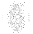
- FIG. 2 is a perspective view showing a right row angular contact ball bearing retainer extracted from the hub unit bearing of FIG. 3 is a partially enlarged view of FIG. 2.
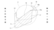
- FIG. 4 is a schematic cross-sectional view taken along the line AA of FIG. 3.
- FIG. 5 shows the angular contact ball bearing retainer and its peripheral portion in order to explain that grease leaks from the grease reservoir groove of the right row angular contact ball bearing retainer in the hub unit bearing of the first example. It is the schematic diagram seen from the direction outer side.
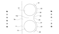
- FIG. 6 is a partially enlarged schematic view of the angular contact ball bearing retainer according to the second embodiment of the present disclosure, taken out and viewed from the outside in the radial direction.
- FIG. 1 A first example of an embodiment of the present disclosure will be described with reference to FIGS. 1 to 5.
- FIG. 1 A first example of an embodiment of the present disclosure will be described with reference to FIGS. 1 to 5.
- an angular contact ball bearing provided with an angular contact ball bearing retainer is applied to a hub unit bearing (double-row angular contact ball bearing) for rotatably supporting a vehicle wheel with respect to a suspension system. .
- the hub unit bearing 1 of this example is a so-called first-generation hub unit bearing, and includes an outer ring 2 corresponding to an outer ring member, a pair of inner rings 3 corresponding to an inner ring member, a plurality of balls 4, It has two angular ball bearing retainers 5 and a pair of combined seal rings 9 each corresponding to a sealing device.
- the outer ring 2 has double-row outer ring raceways 6 each of which is angular on the inner peripheral surface.
- a pair of inner rings 3 are arranged coaxially with the outer ring 2 radially inward of the outer ring 2 in a state in which the small-diameter side end surfaces of the pair of inner rings 3 abut each other.
- the pair of inner rings 3 each have an angular shape on the outer peripheral surface, and have a double-row inner ring raceway 7 radially facing the double-row outer ring raceway 6 .
- a plurality of balls 4 are arranged for each row between the double-row outer ring raceway 6 and the double-row inner ring raceway 7, and are spaced apart in the circumferential direction. 5 to be rollably held.
- the balls 4 arranged in double rows are provided with a contact angle of a back-to-back combination type (DB type).
- DB type back-to-back combination type
- the outer ring 2 is internally fitted and fixed to a knuckle that constitutes a suspension system (not shown) when assembled to the vehicle.
- the pair of inner rings 3 are externally fitted and fixed to a hub axle (not shown) having hub flanges for supporting the wheels. Therefore, in the hub unit bearing 1 of this example, the outer ring 2 serves as a stationary ring that does not rotate during use, and the pair of inner rings 3 serve as rotating rings that rotate during use.
- the axial direction, the radial direction, and the circumferential direction refer to respective directions regarding the small-diameter rim portion 11 constituting the angular ball bearing retainer 5, unless otherwise specified.
- the angular contact ball bearing retainer 5 on the right side in FIG. 1 and the angular contact ball bearing retainer 5 on the left side of FIG. Specifically, regarding the angular contact ball bearing retainer 5 in the right row in FIG. Regarding the vessel 5, the left side is referred to as one axial side, and the right side is referred to as the other axial side.
- the angular ball bearing retainer 5 is integrally made by injection molding (axial draw molding) of synthetic resin, and has a substantially truncated conical shape as a whole.
- the angular contact ball bearing retainer 5 of this example has the features of both the tilt type angular contact ball bearing retainer and the crown type angular contact ball bearing retainer.
- the angular contact ball bearing retainer 5 of the present embodiment has features intermediate between the tilt type angular contact ball bearing retainer and the crown type angular contact ball bearing retainer.
- Synthetic resins constituting the angular contact ball bearing retainer 5 include polyamide 66 (PA66), polyamide 6 (PA6), polyamide 46 (PA46), polyamide 9T (PA9T), polyphenylene sulfide (PPS), polyethylene terephthalate ( Various synthetic resins such as PET), polyacetal (POM), and phenolic resin (PF) can be employed. Various reinforcing fibers such as glass fiber, carbon fiber and aramid fiber can be mixed into these synthetic resins, if necessary.
- the angular ball bearing retainer 5 includes a small-diameter rim portion 11 , a plurality of column portions 12 , and a plurality of pockets 13 for holding the balls 4 .
- the angular contact ball bearing retainer 5 is manufactured by axial draw injection molding using a pair of molds (fixed mold and movable mold) not shown. Therefore, at the boundary between the radially outer portion and the radially inner portion of the inner surface of the pocket 13, there is a parting line 14 that was positioned at the abutting portion of the pair of molds during injection molding.
- the small-diameter rim portion 11 has an annular shape as a whole and is continuous over the entire circumference.
- the outer peripheral surface of the small-diameter rim portion 11 is a cylindrical surface or a tapered surface whose outer diameter increases toward one side in the axial direction.
- the outer peripheral surface of the small-diameter rim portion 11 is a tapered surface with an inclination angle (taper half angle, draft angle) of 6°.
- the inner peripheral surface of the small-diameter rim portion 11 is a cylindrical surface whose inner diameter does not change along the axial direction.
- a side surface on the other side in the axial direction of the small-diameter rim portion 11 is a flat surface arranged on a virtual plane perpendicular to the central axis O5 of the angular contact ball bearing retainer 5 .
- a portion of the side surface on one axial side of the small-diameter rim portion 11 that is circumferentially deviated from the column portion 12 is a concave curved surface having a radius of curvature slightly larger than the radius of curvature of the ball 4 , and is the inner surface of the pocket 13 . configure.
- the plurality of pillars 12 extend toward the one axial side from a plurality of locations in the circumferential direction of the side surface of the small-diameter rim portion 11 on the one axial side. Each of the plurality of pillars 12 is inclined radially outward toward one side in the axial direction.
- the columnar portion 12 has a tapered surface portion on its outer peripheral surface whose outer diameter increases toward one side in the axial direction, and a tapered surface portion whose inner diameter increases toward one axial direction side on its inner peripheral surface. Both side surfaces in the circumferential direction of the column 12 are concave curved surfaces having a radius of curvature slightly larger than the radius of curvature of the ball 4 and form the inner surface of the pocket 13 .
- the column portion 12 has a first branch portion 15 and a second branch portion 16 which are branched and extended in a circumferential direction at one end (tip portion) of the axial direction, and these first branch portions 15 and a grease reservoir groove 17 formed between the second branch portion 16 and the second branch portion 16 .
- the angular ball bearing retainer 5 of this example includes a plurality of first branched portions 15 , a plurality of second branched portions, and a plurality of grease reservoir grooves 17 .
- the first branch portion 15 is provided on one circumferential side portion of the one axial end portion of the column portion 12 . It extends in the direction towards the side (see FIG. 3).
- the second branch portion 16 is provided on the other end portion in the circumferential direction of the one end portion in the axial direction of the column portion 12 . It extends in the direction toward the other side in the circumferential direction (see FIG. 3).
- the first branched portion 15 and the second branched portion 16 have a symmetrical shape with respect to the circumferential direction.
- the first branched portion and the second branched portion may also have an asymmetrical shape with respect to the circumferential direction.
- the distal end portion of the first branch portion 15 of one of the plurality of column portions 12 and the first branch portion 15 adjacent to the one column portion 12 in the circumferential direction extend in the direction of approaching each other in the circumferential direction and are connected in the circumferential direction.
- the tip of the second branched portion 16 of the one column 12 and the tip of the first branched portion 15 of the column 12 adjacent to the one column 12 on the other side in the circumferential direction extend toward each other in the direction and are circumferentially connected.
- the connecting portions between the tip end portions of the first branch portion 15 and the tip end portions of the second branch portion 16 are arranged intermittently in the circumferential direction.
- the first branch portion 15 and the second branch portion 16 each have a substantially V-shaped bent shape when viewed in the radial direction.
- the first branch portion 15 includes a base half portion 15a that extends obliquely toward the one side in the circumferential direction toward the one side in the axial direction, and and a front half portion 15b extending toward one side.
- the side surface of the base half portion 15a on one side in the circumferential direction and the side surface of the front half portion 15b on the other side in the axial direction are smoothly connected.
- a side surface on one side in the circumferential direction of the base half portion 15 a and a side surface on the other side in the axial direction of the front half portion 15 b are concave curved surfaces having a radius of curvature slightly larger than the radius of curvature of the ball 4 . constitute the inner surface of
- the side surface of the base half portion 15a on the other side in the circumferential direction and the side surface of the front half portion 15b on the one side in the axial direction are flat surfaces.
- a side surface on one side in the axial direction of the front half portion 15b is arranged parallel to a side surface on the other side in the axial direction of the small-diameter rim portion 11, and is an imaginary side surface perpendicular to the central axis O5 of the angular contact ball bearing retainer 5 . placed on a plane.
- the second branch portion 16 includes a base half portion 16a that obliquely extends toward the other side in the circumferential direction as it goes toward one side in the axial direction, and It is composed of an elongated front half portion 16b.
- the side surface of the base half portion 16a on the other side in the circumferential direction and the side surface of the front half portion 16b on the other side in the axial direction are smoothly connected.
- a side surface of the base half portion 16 a on the other side in the circumferential direction and a side surface of the front half portion 16 b on the other side in the axial direction are concave curved surfaces having a radius of curvature slightly larger than the radius of curvature of the ball 4 . constitute the inner surface of
- the one side surface in the circumferential direction of the base half portion 16a and the one side surface in the axial direction of the front half portion 16b are flat surfaces.
- a side surface on one axial side of the front half portion 16b is arranged parallel to a side surface on the other axial side of the small-diameter rim portion 11, and is on the same imaginary plane as a side surface on the one axial side of the front half portion 15b. placed above.
- the connecting portion between the distal end portion of the first branch portion 15 and the distal end portion of the second branch portion 16 is the front half portion 15 b of the first branch portion 15 of the column portion 12 and the column portion 12 .
- the front half portion 16b of the second branch portion 16 of the column portion 12 adjacent to one side in the circumferential direction is continuous in the circumferential direction.
- Each of the connecting portions constituted by the front halves 15b and 16b that are continuous in the circumferential direction is formed in a partially annular shape and curved in an arc around the central axis O5 of the angular contact ball bearing retainer 5. are doing.
- the connecting portions formed by the front half portions 15b and 16b that are continuous in the circumferential direction are alternately arranged with the grease reservoir grooves 17 in the circumferential direction.
- the large-diameter rim portions 18 intermittently arranged are formed by the connecting portions formed by the front half portions 15b and 16b that are continuous in the circumferential direction.
- a side surface of each large-diameter rim portion 18 on one side in the axial direction is a flat surface, and is arranged in parallel with a side surface on the other side in the axial direction of the small-diameter rim portion 11 .
- the plurality of grease reservoir grooves 17 have the function of retaining the grease 10 enclosed in the internal space of the hub unit bearing 1.
- the grease reservoir groove 17 has a substantially V shape when viewed in the radial direction.
- the grease reservoir groove 17 is configured by the side surface on the other side in the circumferential direction of the base half portion 15a of the first branch portion 15 and the side surface on the one side in the circumferential direction of the base half portion 16a of the second branch portion 16. It has a pair of flat inner surfaces.
- An included angle ⁇ (see FIG. 3) between a pair of inner side surfaces of the grease reservoir groove 17 can be set, for example, within the range of 30 degrees to 120 degrees, preferably within the range of 70 degrees to 110 degrees. In the illustrated example, the included angle between the pair of inner side surfaces of the grease reservoir groove 17 is 90 degrees.
- the bottom of the grease reservoir groove 17 is located on one side in the axial direction of the center of the pocket 13 .
- Each of the plurality of pockets 13 is surrounded by one axial side surface of the small-diameter rim portion 11 and the circumferentially adjacent column portion 12 (including the other axial side surface of the large-diameter rim portion 18). formed (defined) in the
- the grease 10 also enters the inner space 8 under the influence of centrifugal force when the hub unit bearing 1 is in use (when the inner ring 3 rotates). move radially outward and tend to gather in the space behind the combined seal ring 9 .
- the grease 10 collected in the space behind the combination seal ring 9 is drained off from one axial end of the column portion 12, that is, the large-diameter rim portion 18 (circular The connecting portion formed by the front half portions 15b and 16b that are continuous in the circumferential direction), or the large-diameter rim portion 18 and the grease reservoir groove 17 agitate.
- the agitation resistance is greater than when using a tilted angular contact ball bearing cage that is stirred by the large-diameter annular rim, but when using a crown-type angular contact ball bearing cage, Compared to , the stirring resistance can be kept small.
- the angular contact ball bearing retainer 5 of this example since the large diameter rim portions 18 are arranged intermittently, an inclined type angular contact ball bearing retainer having an annular large diameter rim portion is used. The axial thickness of the large-diameter rim portion 18 can be reduced, and the ball 4 can be arranged in the vicinity of the combination seal ring 9, as compared with the case where the large-diameter rim portion 18 is formed. Therefore, the angular ball bearing retainer 5 of this example is advantageous in securing a long distance between the rows of balls.
- the angular contact ball bearing retainer 5 of this example can be rotated while holding the grease 10b inside the grease reservoir groove 17 .
- the grease 10b held in the grease reservoir groove 17 tends to solidify because it is not agitated.
- an annular gap 19 is formed between the grease 10a solidified behind the combination seal ring 9 and the grease 10b held (solidified) in the grease reservoir groove 17 and the side surface on one axial side of the large-diameter rim portion 18. , the grease 10b can be supplied from the grease reservoir groove 17. As shown in FIG. Therefore, the flow path (characteristic length) is shortened, the Reynolds number of the annular gap 19 is reduced compared to when the grease 10b is not supplied, and a laminar flow can be created in the annular gap 19.
- the grease 10b retained in the grease reservoir groove 17 can be used to reduce the friction generated between the angular contact ball bearing retainer 5 and the solidified grease 10a. It is possible. As a result, the torque of the hub unit bearing 1 can be reduced.
- the shape of the end portion (tip portion) on one axial side of the column portion 12a that constitutes the angular ball bearing retainer 5a is changed from the structure of the first example.
- each of the first branched portion 20 and the second branched portion 21 and the shape of the grease reservoir groove 22 provided at one end in the axial direction of the column portion 12a are changed.
- both the first branched portion 20 and the second branched portion 21 have an arch shape curved in an arc so that the outer side is convex with respect to the diametrical direction of the pocket 13 .
- the tip side of the first branch portion 20 extends in a direction toward one side in the circumferential direction.
- the second branch portion 21 extends in a direction toward the other side in the circumferential direction at its tip side.
- the first branch portion 20 and the second branch portion 21 have a symmetric shape in the circumferential direction, but the first branch portion and the second branch portion have an asymmetric shape in the circumferential direction.
- a tip portion of a first branch portion 20 of one column portion 12a among the plurality of column portions 12a, and a tip portion of a second branch portion 21 of the column portion 12a adjacent to the column portion 12a on one side in the circumferential direction. extend toward each other in the circumferential direction and are connected in the circumferential direction. Further, the tip of the second branch 21 of the one column 12a and the tip of the first branch 20 of the column 12a adjacent to the column 12a on the other side in the circumferential direction extend toward each other in the direction and are circumferentially connected.
- a large-diameter rim portion 23 is formed by a connecting portion formed by the distal end portion of the first branch portion 20 and the distal end portion of the second branch portion 21 that are continuous in the circumferential direction.
- the inner side surface located inside the pocket 13 in the diametrical direction is a concave curved surface having a radius of curvature slightly larger than the radius of curvature of the ball 4, and constitutes the inner surface of the pocket 13. do.
- the outer side surface located on the outer side with respect to the diametrical direction of the pocket 13 is a convex curved surface.
- the thickness (thickness dimension) of the first branch portion 20 in the diametrical direction of the pocket 13 gradually increases toward the base end side of the first branch portion 20 .
- the inner side surface located inside the pocket 13 in the diametrical direction is a concave curved surface having a radius of curvature slightly larger than the radius of curvature of the ball 4, and constitutes the inner surface of the pocket 13. do.
- the inner surface of the second branch portion 21 is smoothly connected to the inner surface of the first branch portion 20 .
- the outer side surface located on the outer side with respect to the diametrical direction of the pocket 13 is a convex curved surface.
- the outer surface of the second branched portion 21 is smoothly connected to the outer surface of the first branched portion 20 .
- the thickness (thickness dimension) of the second branch portion 21 in the diametrical direction of the pocket 13 gradually increases toward the base end side of the second branch portion 21 .
- a connection portion (large-diameter rim portion 23) formed by the distal end portion of the first branch portion 20 and the distal end portion of the second branch portion 21, which are continuous in the circumferential direction, is configured in a partially annular shape, and is an angular contact ball bearing. It is curved in an arc around the central axis O 5 (see FIG. 1) of the retainer 5 for use. Also, the large-diameter rim portions 23 are alternately arranged with the grease reservoir grooves 22 in the circumferential direction.
- a side surface on the one axial side of the large-diameter rim portion 23 is a convex curved surface that is curved so that the one axial side is convex.
- the grease reservoir groove 22 has a substantially U shape when viewed in the radial direction.
- the grease reservoir groove 22 has a pair of convexly curved inner side surfaces formed by a side surface on the other side in the circumferential direction of the first branch portion 20 and a side surface on the one side in the circumferential direction of the second branch portion 21, and a small-diameter rim. It has a flat bottom surface 24 parallel to the side surface on the other side in the axial direction of the portion 11 . Further, each of the pair of inner side surfaces and the bottom surface 24 of the grease reservoir groove 22 are smoothly connected by corner R portions.
- part of the grease 10b (see FIG. 5) held in the grease reservoir groove 22 can be caused to leak rearward in the rotational direction by rotating the angular ball bearing retainer 5a. Therefore, between the solidified grease 10a (see FIG. 5) behind the combination seal ring 9 and the (solidified) grease 10b held (solidified) in the one axial side surface of the large-diameter rim portion 23 and in the grease reservoir groove 22 The grease 10b can be supplied from the grease reservoir groove 22 to the annular gap 19 (see FIG. 5). As a result, a laminar flow can be created in the annular gap 19, and the friction generated between the angular contact ball bearing retainer 5a and the solidified grease 10a can be reduced.
- the grease reservoir groove 22 is provided with the flat bottom surface 24, the amount of the grease 10b that can be held in the grease reservoir groove 22 can be increased compared to the structure of the first example. Therefore, the amount of grease 10b that flows out from grease reservoir groove 22 can be increased. Furthermore, the side surface on one side in the axial direction of the large-diameter rim portion 23 is formed into a convex curved surface to form a nearly streamlined shape. Therefore, the laminar flow formed between the solidified grease 10a behind the combined seal ring 9 and the side surface of the large-diameter rim portion 23 on one side in the axial direction can be made thicker. As a result, the friction generated between the angular ball bearing retainer 5a and the solidified grease 10a can be effectively reduced.
- the structure of this example can increase the radius of curvature of one side surface of the large-diameter rim portion 23 in the axial direction when it is adopted in a structure in which the circumferential distance between the pockets 13 (balls 4) adjacent in the circumferential direction is long. Therefore, it is more advantageous.
- the content of the present disclosure is not limited to this, and can be modified and improved as appropriate. Also, the structures of the first example and the second example can be implemented in combination as long as there is no contradiction.
- the angular contact ball bearing of the present disclosure is not limited to the first generation hub unit bearing, but can be applied to other generation hub unit bearings such as the second generation hub unit bearing and the third generation hub unit bearing. can also In addition, the angular contact ball bearing of the present disclosure can be applied not only to hub unit bearings but also to single-row or double-row angular contact ball bearings incorporated in various mechanical devices.
Landscapes
- Engineering & Computer Science (AREA)
- General Engineering & Computer Science (AREA)
- Mechanical Engineering (AREA)
- Rolling Contact Bearings (AREA)
Priority Applications (3)
| Application Number | Priority Date | Filing Date | Title |
|---|---|---|---|
| CN202280056507.1A CN117859013A (zh) | 2022-01-07 | 2022-12-14 | 角接触滚珠轴承用保持器及角接触滚珠轴承 |
| EP22918782.8A EP4461980A4 (en) | 2022-01-07 | 2022-12-14 | Angular contact ball bearing cage and angular contact ball bearing |
| US18/708,299 US20250012322A1 (en) | 2022-01-07 | 2022-12-14 | Angular ball bearing cage and angular ball bearing |
Applications Claiming Priority (2)
| Application Number | Priority Date | Filing Date | Title |
|---|---|---|---|
| JP2022-001834 | 2022-01-07 | ||
| JP2022001834A JP2023101289A (ja) | 2022-01-07 | 2022-01-07 | アンギュラ玉軸受用保持器及びアンギュラ玉軸受 |
Publications (1)
| Publication Number | Publication Date |
|---|---|
| WO2023132196A1 true WO2023132196A1 (ja) | 2023-07-13 |
Family
ID=87073514
Family Applications (1)
| Application Number | Title | Priority Date | Filing Date |
|---|---|---|---|
| PCT/JP2022/046078 Ceased WO2023132196A1 (ja) | 2022-01-07 | 2022-12-14 | アンギュラ玉軸受用保持器およびアンギュラ玉軸受 |
Country Status (5)
| Country | Link |
|---|---|
| US (1) | US20250012322A1 (https=) |
| EP (1) | EP4461980A4 (https=) |
| JP (1) | JP2023101289A (https=) |
| CN (1) | CN117859013A (https=) |
| WO (1) | WO2023132196A1 (https=) |
Citations (5)
| Publication number | Priority date | Publication date | Assignee | Title |
|---|---|---|---|---|
| JPH0814258A (ja) * | 1994-06-28 | 1996-01-16 | Ntn Corp | 軸受用保持器および軸受 |
| JP2016070470A (ja) * | 2014-10-02 | 2016-05-09 | Ntn株式会社 | 転がり軸受 |
| JP2018059546A (ja) | 2016-10-03 | 2018-04-12 | 日本精工株式会社 | アンギュラ玉軸受用の保持器及びハブユニット軸受 |
| JP2020133741A (ja) | 2019-02-19 | 2020-08-31 | 日本精工株式会社 | 傾斜型冠形保持器及びアンギュラ玉軸受 |
| JP2021181811A (ja) * | 2020-05-20 | 2021-11-25 | 日本精工株式会社 | 保持器及び保持器を用いた車輪用軸受装置 |
Family Cites Families (1)
| Publication number | Priority date | Publication date | Assignee | Title |
|---|---|---|---|---|
| DE3247948C2 (de) * | 1982-12-24 | 1985-10-17 | SKF GmbH, 8720 Schweinfurt | Käfig für Kugellager, insbesondere für Schrägkugellager |
-
2022
- 2022-01-07 JP JP2022001834A patent/JP2023101289A/ja active Pending
- 2022-12-14 EP EP22918782.8A patent/EP4461980A4/en not_active Withdrawn
- 2022-12-14 WO PCT/JP2022/046078 patent/WO2023132196A1/ja not_active Ceased
- 2022-12-14 CN CN202280056507.1A patent/CN117859013A/zh active Pending
- 2022-12-14 US US18/708,299 patent/US20250012322A1/en active Pending
Patent Citations (5)
| Publication number | Priority date | Publication date | Assignee | Title |
|---|---|---|---|---|
| JPH0814258A (ja) * | 1994-06-28 | 1996-01-16 | Ntn Corp | 軸受用保持器および軸受 |
| JP2016070470A (ja) * | 2014-10-02 | 2016-05-09 | Ntn株式会社 | 転がり軸受 |
| JP2018059546A (ja) | 2016-10-03 | 2018-04-12 | 日本精工株式会社 | アンギュラ玉軸受用の保持器及びハブユニット軸受 |
| JP2020133741A (ja) | 2019-02-19 | 2020-08-31 | 日本精工株式会社 | 傾斜型冠形保持器及びアンギュラ玉軸受 |
| JP2021181811A (ja) * | 2020-05-20 | 2021-11-25 | 日本精工株式会社 | 保持器及び保持器を用いた車輪用軸受装置 |
Non-Patent Citations (1)
| Title |
|---|
| See also references of EP4461980A4 |
Also Published As
| Publication number | Publication date |
|---|---|
| EP4461980A1 (en) | 2024-11-13 |
| EP4461980A4 (en) | 2025-12-17 |
| CN117859013A (zh) | 2024-04-09 |
| JP2023101289A (ja) | 2023-07-20 |
| US20250012322A1 (en) | 2025-01-09 |
Similar Documents
| Publication | Publication Date | Title |
|---|---|---|
| CN102648357B (zh) | 多列球轴承设施 | |
| US8382380B2 (en) | Tapered roller bearing | |
| JPH11182537A (ja) | 車輪用転がり軸受ユニット | |
| WO2023132196A1 (ja) | アンギュラ玉軸受用保持器およびアンギュラ玉軸受 | |
| JP2018059546A (ja) | アンギュラ玉軸受用の保持器及びハブユニット軸受 | |
| WO2021100500A1 (ja) | アンギュラ玉軸受用保持器、アンギュラ玉軸受、および、ハブユニット軸受 | |
| WO2023013508A1 (ja) | 車輪用軸受装置 | |
| JP7243278B2 (ja) | 傾斜型保持器及びアンギュラ玉軸受 | |
| JP7491050B2 (ja) | 車輪用軸受装置 | |
| JP2021143739A (ja) | アンギュラ玉軸受用保持器及びアンギュラ玉軸受 | |
| JP2023075627A (ja) | アンギュラ玉軸受用保持器およびアンギュラ玉軸受 | |
| JP2020133741A (ja) | 傾斜型冠形保持器及びアンギュラ玉軸受 | |
| WO2024018551A1 (ja) | 転がり軸受 | |
| JP7726023B2 (ja) | 車輪支持用転がり軸受ユニット | |
| JP7764159B2 (ja) | 車輪用軸受装置 | |
| US20250060005A1 (en) | Sealing member having internal pressure discharging function and bearing device provided therewith | |
| JP7643974B2 (ja) | 車輪用軸受装置 | |
| JP2025128507A (ja) | アンギュラ玉軸受 | |
| JP7440349B2 (ja) | 車輪支持用転がり軸受ユニット | |
| JP2009228858A (ja) | 玉軸受及び冠型保持器 | |
| JP2000038003A (ja) | 車輪用転がり軸受ユニット | |
| JP2023039249A (ja) | 複列アンギュラ玉軸受の保持器 | |
| JP2012072818A (ja) | 車輪用軸受 | |
| JP7779748B2 (ja) | 軸受装置用保持器及びそれを備える車輪用軸受装置 | |
| JP2011190859A (ja) | 転がり軸受 |
Legal Events
| Date | Code | Title | Description |
|---|---|---|---|
| 121 | Ep: the epo has been informed by wipo that ep was designated in this application |
Ref document number: 22918782 Country of ref document: EP Kind code of ref document: A1 |
|
| WWE | Wipo information: entry into national phase |
Ref document number: 202280056507.1 Country of ref document: CN |
|
| WWE | Wipo information: entry into national phase |
Ref document number: 18708299 Country of ref document: US |
|
| WWE | Wipo information: entry into national phase |
Ref document number: 2022918782 Country of ref document: EP |
|
| NENP | Non-entry into the national phase |
Ref country code: DE |
|
| ENP | Entry into the national phase |
Ref document number: 2022918782 Country of ref document: EP Effective date: 20240807 |
|
| WWW | Wipo information: withdrawn in national office |
Ref document number: 2022918782 Country of ref document: EP |