WO2023127084A1 - ロータ、モータ、ファン、換気扇、及び空気調和機 - Google Patents
ロータ、モータ、ファン、換気扇、及び空気調和機 Download PDFInfo
- Publication number
- WO2023127084A1 WO2023127084A1 PCT/JP2021/048762 JP2021048762W WO2023127084A1 WO 2023127084 A1 WO2023127084 A1 WO 2023127084A1 JP 2021048762 W JP2021048762 W JP 2021048762W WO 2023127084 A1 WO2023127084 A1 WO 2023127084A1
- Authority
- WO
- WIPO (PCT)
- Prior art keywords
- conductive
- motor
- rotor
- bearing
- rotor portion
- Prior art date
- Legal status (The legal status is an assumption and is not a legal conclusion. Google has not performed a legal analysis and makes no representation as to the accuracy of the status listed.)
- Ceased
Links
Images


Classifications
-
- H—ELECTRICITY
- H02—GENERATION; CONVERSION OR DISTRIBUTION OF ELECTRIC POWER
- H02K—DYNAMO-ELECTRIC MACHINES
- H02K7/00—Arrangements for handling mechanical energy structurally associated with dynamo-electric machines, e.g. structural association with mechanical driving motors or auxiliary dynamo-electric machines
- H02K7/14—Structural association with mechanical loads, e.g. with hand-held machine tools or fans
-
- H—ELECTRICITY
- H02—GENERATION; CONVERSION OR DISTRIBUTION OF ELECTRIC POWER
- H02K—DYNAMO-ELECTRIC MACHINES
- H02K1/00—Details of the magnetic circuit
- H02K1/02—Details of the magnetic circuit characterised by the magnetic material
-
- H—ELECTRICITY
- H02—GENERATION; CONVERSION OR DISTRIBUTION OF ELECTRIC POWER
- H02K—DYNAMO-ELECTRIC MACHINES
- H02K1/00—Details of the magnetic circuit
- H02K1/06—Details of the magnetic circuit characterised by the shape, form or construction
- H02K1/22—Rotating parts of the magnetic circuit
- H02K1/27—Rotor cores with permanent magnets
- H02K1/2706—Inner rotors
- H02K1/272—Inner rotors the magnetisation axis of the magnets being perpendicular to the rotor axis
- H02K1/2726—Inner rotors the magnetisation axis of the magnets being perpendicular to the rotor axis the rotor consisting of a single magnet or two or more axially juxtaposed single magnets
- H02K1/2733—Annular magnets
-
- H—ELECTRICITY
- H02—GENERATION; CONVERSION OR DISTRIBUTION OF ELECTRIC POWER
- H02K—DYNAMO-ELECTRIC MACHINES
- H02K1/00—Details of the magnetic circuit
- H02K1/06—Details of the magnetic circuit characterised by the shape, form or construction
- H02K1/22—Rotating parts of the magnetic circuit
- H02K1/28—Means for mounting or fastening rotating magnetic parts on to, or to, the rotor structures
- H02K1/30—Means for mounting or fastening rotating magnetic parts on to, or to, the rotor structures using intermediate parts, e.g. spiders
-
- H—ELECTRICITY
- H02—GENERATION; CONVERSION OR DISTRIBUTION OF ELECTRIC POWER
- H02K—DYNAMO-ELECTRIC MACHINES
- H02K5/00—Casings; Enclosures; Supports
- H02K5/04—Casings or enclosures characterised by the shape, form or construction thereof
- H02K5/16—Means for supporting bearings, e.g. insulating supports or means for fitting bearings in the bearing-shields
- H02K5/161—Means for supporting bearings, e.g. insulating supports or means for fitting bearings in the bearing-shields radially supporting the rotary shaft at both ends of the rotor
-
- H—ELECTRICITY
- H02—GENERATION; CONVERSION OR DISTRIBUTION OF ELECTRIC POWER
- H02K—DYNAMO-ELECTRIC MACHINES
- H02K2213/00—Specific aspects, not otherwise provided for and not covered by codes H02K2201/00 - H02K2211/00
- H02K2213/03—Machines characterised by numerical values, ranges, mathematical expressions or similar information
Definitions
- the present disclosure relates to rotors, motors, fans, ventilation fans, and air conditioners.
- bearing voltage the voltage generated between the inner ring and outer ring of the bearing
- the discharge current flowing through the bearing increases.
- electrolytic corrosion occurs in the bearings, increasing vibration and noise in the motor.
- An object of the present disclosure is to solve the above problems, and to reduce the bearing voltage and suppress the discharge current flowing in the bearing even when a bonded magnet with a dielectric constant greater than 40 is used for the rotor. , to suppress an increase in motor vibration and noise.
- the rotor of the present disclosure includes: an outer rotor portion; an inner rotor section provided inside the outer rotor section, the outer rotor portion is a bonded magnet having a dielectric constant of greater than 40 and less than or equal to 200;
- the motor of the present disclosure is a stator; and the rotor disposed inside the stator.
- a fan according to another aspect of the present disclosure includes: feathers and and the motor that rotates the blade.
- a ventilation fan according to another aspect of the present disclosure includes: feathers and and the motor that rotates the blade.
- An air conditioner according to another aspect of the present disclosure includes indoor unit and and an outdoor unit connected to the indoor unit, Each of the indoor unit, the outdoor unit, or the indoor unit and the outdoor unit has the motor.
- the bearing voltage can be reduced, the discharge current flowing in the bearing can be suppressed, and the motor vibration and An increase in noise can be suppressed.
- FIG. 1 is a cross-sectional view schematically showing a motor according to Embodiment 1;
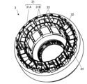
- FIG. It is a perspective view which shows a stator roughly.
- It is a circuit diagram which shows an example of an electric circuit.
- It is a sectional view showing roughly the structure of a rotating body.
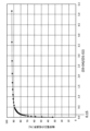
- 7 is a graph showing the reduction rate of the bearing voltage in the motor according to Embodiment 1 with respect to the motor for comparison.
- FIG. 6 is a diagram schematically showing a fan according to Embodiment 2;
- FIG. FIG. 11 is a diagram schematically showing a ventilation fan according to Embodiment 3;
- FIG. 10 is a diagram schematically showing the configuration of an air conditioner according to Embodiment 4;
- Embodiment 1 A motor 1 according to Embodiment 1 will be described below.
- the z-axis direction (z-axis) indicates a direction parallel to the axis A1 of the motor 1
- the x-axis direction (x-axis) indicates a direction orthogonal to the z-axis direction.
- the y-axis direction (y-axis) indicates a direction orthogonal to both the z-axis direction and the x-axis direction.
- the axis A ⁇ b>1 is the center of rotation of the rotor 2 , that is, the rotation axis of the rotor 2 .
- the direction parallel to the axis A1 is also referred to as "the axial direction of the rotor 2" or simply “the axial direction”.
- the radial direction is the radial direction of the rotor 2, the stator 3, or the stator core 31, and is the direction perpendicular to the axis A1.
- the xy plane is a plane perpendicular to the axial direction.
- the circumferential direction of the rotor 2, stator 3, or stator core 31 is also simply referred to as "circumferential direction”.
- FIG. 1 is a sectional view schematically showing a motor 1 according to Embodiment 1.
- the motor 1 has a rotor 2 , a stator 3 , a non-conductive member 4 and a conductive housing 5 .
- Motor 1 is, for example, a permanent magnet synchronous motor.
- the motor 1 may further have an electric circuit 6 and a connector 7.
- the rotor 2 and stator 3 are arranged in a conductive housing 5 .
- the stator 3 has a stator core 31, at least one insulator 32, at least one coil 33, and at least one conducting pin 34. Each coil 33 is wound around the insulator 32 .
- the stator 3 is press-fitted into the frame 5A of the conductive housing 5. As shown in FIG. That is, the outer peripheral surface of the stator 3 (for example, the outer peripheral surface of the stator core 31 ) is in contact with the conductive housing 5 .
- FIG. 2 is a perspective view schematically showing the stator 3.
- FIG. 2 coils 33 are removed from stator 3 to show the structure of stator core 31 and insulator 32 .
- the stator core 31 has a yoke 31A extending in the circumferential direction and a plurality of teeth 31B.
- stator core 31 has twelve teeth 31B.
- Each tooth 31B extends radially from the yoke 31A.
- Stator core 31 is a cylindrical core.
- the stator core 31 is formed of a plurality of magnetic steel sheets laminated in the axial direction. In this case, each of the plurality of electromagnetic steel sheets is formed into a predetermined shape by punching. These electromagnetic steel sheets are fixed to each other by caulking, welding, adhesion, or the like.
- the coil 33 is a three-phase coil having U-phase, V-phase, and W-phase.
- Each insulator 32 is provided on the teeth 31B.
- Each insulator 32 is, for example, a thermoplastic resin such as polybutylene terephthalate (PBT).
- PBT polybutylene terephthalate
- Each insulator 32 electrically insulates the stator core 31 (specifically, each tooth 31B of the stator core 31).
- insulator 32 is molded integrally with stator core 31 .
- the insulator 32 may be molded in advance and the molded insulator 32 may be combined with the stator core 31 .
- Each conduction pin 34 is fixed to the insulator 32, for example.
- Each conducting pin 34 electrically connects the coil 33 and the electric circuit 6 .
- each conduction pin 34 electrically connects the coil 33 and the switching circuit 64 b of the inverter circuit 64 of the electric circuit 6 .
- FIG. 3 is a circuit diagram showing an example of the electric circuit 6. As shown in FIG. In the example shown in FIG. 3 , the electric circuit 6 has a fuse 61 , a filter circuit 62 , a power supply circuit 63 and an inverter circuit 64 . The electric circuit 6 is configured to be electrically connected to an AC power supply 60 .
- an alternating current for example, AC 100 V to AC 240 V
- the alternating current is supplied to the power supply circuit 63 through the fuse 61 and the filter circuit 62 .
- the alternating current is converted to direct current by the power supply circuit 63 .
- the filter circuit 62 has a capacitor 62a, a common mode choke coil 62b, and Y capacitors 62c and 62d. With this configuration, the filter circuit 62 constitutes a noise filter.
- the power supply circuit 63 has a rectifier circuit 63a, a smoothing capacitor 63b, and a switching power supply 63c.
- the alternating current input through the filter circuit 62 is full-wave rectified by the rectifier circuit 63a having a diode bridge, and is thereby converted to direct current.
- the direct current is accumulated in the smoothing capacitor 63b.
- a direct current for example, DC140V or DC280V
- the switching power supply 63c uses the direct current generated in the smoothing capacitor 63b to generate the control power (for example, DC 15V) required by the drive circuit 64a.
- the inverter circuit 64 has a drive circuit 64a and a switching circuit 64b.
- the switching circuit 64b constitutes a three-phase bridge of U-phase, V-phase, and W-phase formed between the positive bus and the negative bus.
- the positive bus line is connected to the positive terminal of the smoothing capacitor 63b, and the negative bus line is connected to the negative terminal of the smoothing capacitor 63b.
- the three transistors on the positive bus line side are upper arm transistors.
- the three transistors on the negative bus line side are lower arm transistors.
- Each switching element is connected in antiparallel to a freewheeling diode.
- a connection terminal of each of the upper arm transistor and the lower arm transistor constitutes an output terminal and is connected to the U-phase, V-phase, or W-phase of the coil 33 .
- the driving circuit 64a generates a PWM signal for turning on and off six switching elements of the switching circuit 64b.
- the motor 1 is driven by magnetic pole position sensorless driving without using a magnetic pole position sensor such as a Hall IC.
- the motor 1 has magnetic pole position estimation means for estimating the magnetic pole position of the rotor 2 .
- the magnetic pole position estimation means estimates the position of the rotor 2 from the current flowing through the coil 33 and the motor constant, and generates PWM signals for controlling the current supplied to each phase of the coil 33 . As a result, the rotor 2 rotates.
- the rotor 2 is rotatably arranged inside the stator 3 .
- An air gap exists between the rotor 2 and the stator 3 .
- the rotor 2 has a conductive shaft 21, a rotating body 22, and first and second bearings 23, 24 that rotatably support the conductive shaft 21. As shown in FIG.
- the rotor 2 is rotatable around a rotation axis (that is, axis A1).
- the rotating body 22 is fixed to the conductive shaft 21 .
- the rotating body 22 is positioned between the first bearing 23 and the second bearing 24 .
- Conductive shaft 21 is rotatably supported by first bearing 23 and second bearing 24 .
- the conductive shaft 21 is made of metal such as iron, for example.
- the first bearing 23 is located on the load side of the motor 1 with respect to the rotor 22 .
- the first bearing 23 rotatably supports the load side of the conductive shaft 21 .
- the second bearing 24 is located on the side opposite to the load of the motor 1 with respect to the rotating body 22 .
- a second bearing 24 rotatably supports the non-load side of the conductive shaft 21 .
- the load side of the conductive shaft 21 protrudes outside the conductive housing 5 , and the anti-load side of the conductive shaft 21 does not protrude outside the conductive housing 5 .
- the anti-load side of the conductive shaft 21 does not protrude outside the conductive housing 5, but the anti-load side of the conductive shaft 21 may protrude outside the conductive housing 5.
- the outer diameter of the end portion of the conductive shaft 21 on the non-load side is smaller than the outer diameter of the other portion of the conductive shaft 21 .
- the non-conductive member 4 covers the end of the conductive shaft 21 on the non-load side.
- the load side of the conductive shaft 21 is provided with vanes for generating airflow.
- the non-conductive member 4 covers the end of the conductive shaft 21 on the non-load side, the bearing voltage in the second bearing 24 can be reduced.
- a non-conductive member may be provided on the load side of the conductive shaft 21 . In this case, the bearing voltage in the first bearing 23 can be reduced.
- FIG. 4 is a cross-sectional view schematically showing the structure of the rotor 22.
- the rotating body 22 has an outer rotor portion 22A and an inner rotor portion 22B provided inside the outer rotor portion 22A.
- the outer rotor portion 22A is ring-shaped.
- the outer rotor portion 22A is arranged outside the inner rotor portion 22B and integrated with the inner rotor portion 22B.
- the conductive shaft 21 is fixed inside the inner rotor portion 22B.
- D1 is the outer diameter of the outer rotor portion 22A
- D2 is the inner diameter of the outer rotor portion 22A
- D3 is the outer diameter of the inner rotor portion 22B
- D4 is the inner diameter of the inner rotor portion 22B.
- D2 D3.
- the outer rotor portion 22A forms the magnetic poles of the rotor 2 (specifically, the rotating body 22).
- the outer rotor portion 22A is oriented along the applied magnetic field.
- the orientation of the magnetic field is polar anisotropic orientation.
- the outer rotor portion 22A has N poles and S poles alternately formed in the circumferential direction.
- the rotating body 22 (specifically, the outer rotor portion 22A) forms eight poles.
- the number of magnetic poles is not limited to 8 poles.
- the number of magnetic poles may be 2 or more, and does not necessarily have to be 8 poles.
- the outer rotor portion 22A is arranged on the outermost periphery of the rotating body 22.
- the outer rotor portion 22A is a bonded magnet.
- the inner rotor portion 22B is an insulator containing resin, elastomer, air, or the like.
- the insulator forming the inner rotor portion 22B is, for example, a resin such as polyamide resin or polybutylene terephthalate.
- the inner rotor portion 22B is made of resin with a dielectric constant of 10 or less.
- the resin forming the inner rotor portion 22B is polyamide resin or polybutylene terephthalate, the inner rotor portion 22B can be manufactured by injection molding, and the rotor 2 can be shaped more freely.
- the bonded magnets forming the outer rotor portion 22A are made of, for example, a composite containing resin and magnetic powder.
- this bonded magnet is obtained by injection molding resin and magnetic powder.
- Magnetic powders used in bond magnets are ferrites such as strontium ferrite (SrO.6Fe 2 O 3 ) and barium ferrite (BaO/6F 2 O 3 ). If the magnetic powder is ferrite, the cost of the rotor 2 can be reduced.
- Resins used for bond magnets are thermoplastic resins such as polyamide resins (6PA, 12PA, PA6T) and polyphenylene sulfide (PPS).
- the rotor 2 (specifically, the rotating body 22) with high mechanical strength and good heat resistance can be obtained.
- 12PA provides a bonded magnet with less water absorption and less variation in dielectric constant than 6PA.
- PPS polyphenylene sulfide
- the dielectric constant of resin is about 3 to 10.
- the dielectric constant of ferrite is about 250, which is much higher than that of resin.
- the dielectric constant ⁇ r of a bonded magnet containing ferrite was measured.
- the dielectric constant is measured by making a cube-shaped square piece, pasting aluminum foil on the opposing surface of the square piece, and measuring the capacitance between both ends with an LCR meter.
- the dielectric constant was calculated from the formula.
- the measurement conditions for the capacitance are a frequency of 16 kHz, a voltage of 1.5 V, and a temperature of 20.degree.
- ⁇ r C ⁇ d/(S ⁇ 0 )
- C capacitance [F]
- d distance between opposing measurement surfaces [m]
- S area of measurement surface [m 2 ]
- ⁇ 0 Permittivity of vacuum (8.854 ⁇ 10 ⁇ 12 [F/m])
- the dielectric constants of the bonded magnets containing ferrite of 32 samples with different conditions such as the elapsed time after molding and the material lot are in the range where the lower limit is greater than 40 and the upper limit is 200 or less. found to be widely distributed. That is, the relative permittivity of the bond magnet has a great influence on the bearing voltage. Therefore, it is desirable that the outer rotor portion 22A be a bond magnet with a dielectric constant of more than 40 and 200 or less.
- FIG. 5 is a graph showing the reduction rate of the bearing voltage in the motor 1 according to Embodiment 1 with respect to the motors to be compared.
- the horizontal axis is (D3-D4)/(D1-D2).
- the vertical axis represents the reduction rate of the bearing voltage in the motor 1 according to the present embodiment when the bearing voltage in the motor for comparison is used as a reference. In other words, the vertical axis indicates that the bearing voltage decreases as the reduction rate increases, and indicates that the bearing voltage becomes 0 V at a reduction rate of 100%.
- the rotor for comparison has a ring shape with an outer diameter of ⁇ 42 mm and an inner diameter of ⁇ 8 mm. That is, in the motor for comparison, the rotating body is composed only of bond magnets.
- the reduction rate of the bearing voltage with respect to the rotor for comparison changes almost linearly up to about 80%, and the rate of change gradually decreases in the region of the reduction rate of 80% or more.
- (D3-D4)/(D1-D2) when the reduction rate is 80% is 0.15. Therefore, when (D3-D4)/(D1-D2) is 0.15 or more, the bearing voltage can be effectively reduced, and the life of the bearing can be extended.
- the outer diameter of the outer rotor portion 22A is D1
- the inner diameter of the outer rotor portion 22A is D2
- the outer diameter of the inner rotor portion 22B is D3
- the inner diameter of the inner rotor portion 22B is D4.
- the first bearing 23 has a first conductive inner ring 23A, a first conductive outer ring 23B, and two or more balls 23C. Two or more balls 23C are arranged between the first conductive inner ring 23A and the first conductive outer ring 23B. Each ball 23C is electrically conductive. Each ball 23C is filled with a lubricant. The lubricant filled in each ball 23C is non-conductive.
- the first conductive inner ring 23A, the first conductive outer ring 23B, and each ball 23C are made of metal such as iron, for example.
- the first conductive inner ring 23A is fixed to the conductive shaft 21. That is, the first conductive inner ring 23A is in contact with the conductive shaft 21. As shown in FIG.
- the first conductive inner ring 23A is fixed to the conductive shaft 21 by, for example, press fitting or adhesive.
- a thin oil film layer is formed between the outer peripheral surface, which is the raceway surface of the first conductive inner ring 23A, and each ball 23C
- the first conductive A thin oil film layer is formed between the inner peripheral surface, which is the raceway surface of the outer ring 23B, and each ball 23C.
- the first conductive inner ring 23A and the first conductive outer ring 23B are electrically isolated from each ball 23C.
- the outer diameter of the first bearing 23 (specifically, the first conductive outer ring 23B) and the inner diameter of the first housing 51 of the frame 5A are substantially equal.
- the first bearing 23 (specifically, the first conductive outer ring 23B) is fixed to the first housing 51 by, for example, press fitting or adhesive.
- the first conductive outer ring 23B is in contact with the conductive housing 5.
- the first bearing 23 (specifically, the first conductive outer ring 23B) may be arranged in the first housing 51 with a clearance fit.
- the second bearing 24 has a second conductive inner ring 24A, a second conductive outer ring 24B, and two or more balls 24C. Two or more balls 24C are positioned between second conductive inner ring 24A and second conductive outer ring 24B. Each ball 24C is electrically conductive. Lubricant is applied to each ball 24C. The lubricant applied to each ball 24C is non-conductive.
- the second conductive inner ring 24A, the second conductive outer ring 24B, and each ball 24C are made of metal such as iron, for example.
- the second conductive inner ring 24A is fixed to the non-conductive member 4 by, for example, press fitting or adhesive.
- a thin oil film layer is formed between the outer peripheral surface, which is the raceway surface of the second conductive inner ring 24A, and each ball 24C.
- a thin oil film layer is formed between the inner peripheral surface, which is the raceway surface of the second conductive outer ring 24B, and each ball 24C.
- the outer diameter of the second bearing 24 (specifically, the second conductive outer ring 24B) and the inner diameter of the second housing 52 of the bracket 5B are substantially equal.
- the second bearing 24 (specifically, the second conductive outer ring 24B) is fixed to the conductive housing 5 (specifically, the second housing 52 of the bracket 5B) by, for example, press fitting or adhesive. It is In this embodiment, the second conductive outer ring 24B is in contact with the conductive housing 5. As shown in FIG. Even if the second bearing 24 (specifically, the second conductive outer ring 24B) is arranged in the conductive housing 5 (specifically, the second housing 52 of the bracket 5B) with a clearance fit, good.
- the thickness of the oil film layer is, for example, 1 ⁇ m or less, but the thickness of the oil film layer changes depending on several factors such as the rotational speed of the rotor 2 and the temperature inside the motor 1 .
- a preload spring is provided between the second bearing 24 and the bracket 5B (specifically, the second housing 52) to apply preload to the second bearing 24 in the axial direction. Since the preload in the axial direction is applied to the first bearing 23 and the second bearing 24 by the preload spring, rattling of the balls 23C and 24C during the rotation of the rotor 2 can be prevented.
- the size of the first bearing 23 is equal to the size of the second bearing 24. Therefore, the outer diameter (ie, diameter) of first conductive outer ring 23B is equal to the outer diameter (ie, diameter) of second conductive outer ring 24B.
- Each of the first bearing 23 and the second bearing 24 is, for example, a 608-type deep groove ball bearing having an outer diameter of 22 mm, an inner diameter of 8 mm, and a width of 7 mm.
- the size of the first bearing 23 is equal to the size of the second bearing 24 in this embodiment, the size of the first bearing 23 may be different from the size of the second bearing 24 .
- the conductive housing 5 has a frame 5A in which the stator 3 and the rotor 2 are arranged, and a bracket 5B that covers the inside of the frame 5A. That is, the stator 3 and rotor 2 are arranged in a conductive housing 5 (specifically, a frame 5A).
- the conductive housing 5 is made of metal such as iron, for example.
- the frame 5A is a conductive frame.
- the frame 5A is made of metal such as iron, for example.
- the inner surface of frame 5A is mechanically and electrically connected to the outer peripheral surface of stator core 31 .
- the stator 3 is grounded through the frame 5A.
- the frame 5A is, for example, a cup-shaped frame.
- the frame 5A has a first housing 51 in which a first bearing 23 is arranged.
- the first housing 51 is part of the frame 5A and is provided at the bottom of the frame 5A.
- the first housing 51 is a portion of the bottom of the frame 5A that protrudes in the axial direction and the direction perpendicular to the axial direction in the xy plane.
- the first conductive outer ring 23B of the first bearing 23 is in contact with the first housing 51 .
- the first housing 51 has a through hole 51A, and the conductive shaft 21 protrudes out of the frame 5A through the through hole 51A.
- the bracket 5B is a conductive bracket.
- the bracket 5B is made of metal such as iron, for example.
- the frame 5A and bracket 5B are electrically connected.
- Bracket 5B has a second housing 52 in which second bearing 24 is arranged. A portion of the bracket 5B other than the second housing 52 is, for example, a flat plate.
- the second housing 52 is a part of the bracket 5B, and is a part of the bracket 5B that protrudes axially from the flat plate. In the example shown in FIG. 1, the second conductive outer ring 24B of the second bearing 24 contacts the second housing 52. In the example shown in FIG.
- the first conductive outer ring 23B of the first bearing 23 and the second conductive outer ring 24B of the second bearing 24 can be easily configured. can be brought to the same potential, and the bearing voltage can be reduced.
- the conductive housing 5 may further have a circuit cover 5C.
- Circuit cover 5C is a conductive cover.
- the circuit cover 5C is made of metal such as iron, for example.
- the circuit cover 5C may be made of resin.
- the circuit cover 5C covers the electric circuit 6.
- the circuit cover 5C covers the electric circuit 6 together with the bracket 5B.
- a circuit case 5D for fixing the electric circuit 6 may be arranged inside the circuit cover 5C.
- the circuit case 5D is arranged inside the circuit cover 5C.
- Circuit case 5D is fixed to bracket 5B, for example.
- Circuit case 5D is a non-conductive case.
- the circuit case 5D is made of non-conductive resin, for example. For example, by press molding, a recess in which the electric circuit 6 is arranged is formed in the circuit case 5D.
- Each of the frame 5A, bracket 5B, and circuit cover 5C has a flange 53 forming an outer peripheral edge.
- the frame 5A, the bracket 5B, and the flanges 53 of the circuit cover 5C are fixed to each other with screws, for example. Therefore, the frame 5A, bracket 5B, and circuit cover 5C are mechanically coupled and electrically connected to each other. That is, in the example shown in FIG. 1, the conductive housing 5 is partitioned by the bracket 5B into a motor housing portion 54 in which the rotor 2 and the stator 3 are arranged, and a circuit housing portion 55 in which the electric circuit 6 is arranged. It is, in the example shown in FIG. 1, the conductive housing 5 is partitioned by the bracket 5B into a motor housing portion 54 in which the rotor 2 and the stator 3 are arranged, and a circuit housing portion 55 in which the electric circuit 6 is arranged. It is
- the frame 5A, bracket 5B, and circuit cover 5C may be electrically connected to each other.
- the frame 5A and the bracket 5B are made of a conductive material in this embodiment, one of the frame 5A and the bracket 5B may be made of a non-conductive material such as a non-conductive resin. and bracket 5B may be made of a non-conductive material such as a non-conductive resin.
- a non-conductive member such as a non-conductive resin may be arranged between the first conductive inner ring 23A and the conductive shaft 21. With this configuration, the bearing voltage in the first bearing 23 can be reduced.
- the above non-conductive resin is, for example, bulk molding compound resin (BMC resin) such as unsaturated polyester.
- BMC resin bulk molding compound resin
- the dimensional accuracy of the parts can be increased, and the mechanical strength of the motor 1 can be increased.
- connector 7 is fixed to circuit cover 5C.
- the connector 7 has, for example, wiring and a non-conductive cover covering the wiring.
- the wiring of the connector 7 is connected to the electric circuit 6 .
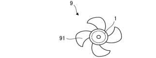
- FIG. 6 is a diagram schematically showing fan 9 according to the second embodiment.
- the fan 9 has blades 91 and a motor 1 .
- the fan 9 is also called a blower.
- the vanes 91 are made of, for example, polypropylene (PP) containing glass fibers.
- the blades 91 are, for example, sirocco fans, propeller fans, cross-flow fans, or turbo fans.
- the motor 1 is the motor 1 according to the first embodiment.
- Blade 91 is fixed to the shaft of motor 1 .
- a motor 1 drives the blades 91 .
- the motor 1 rotates the vane 91 .
- the blades 91 are rotated to generate an airflow. Thereby, the fan 9 can blow air.
- the fan 9 according to Embodiment 2 has the motor 1 according to Embodiment 1, the same advantages as those described in Embodiment 1 can be obtained. Furthermore, the performance of the fan 9 can be maintained for a long period of time.
- the fan 9 according to Embodiment 2 has the motor 1 according to Embodiment 1, vibration and noise in the fan 9 can be reduced.
- FIG. 7 is a diagram schematically showing the ventilation fan 8 according to Embodiment 3.
- the ventilation fan 8 has blades 81 and a motor 1 that rotates the blades 81 .
- the motor 1 is the motor 1 described in the first embodiment.
- a vane 81 is fixed to the load side of the electrically conductive shaft 21 of the motor 1 .
- the ventilation fan 8 can be used for a wide range of purposes such as residential use and business use. For example, it is used in residential living rooms, kitchens, bathrooms and toilets.
- the blades 81 and at least part of the motor 1 are covered with a fan body 82 .
- the conductive housing 5 of the motor 1 is fixed to the ventilation fan body 82 with screws 83 .
- the ventilation fan body 82 is provided with a power connection terminal block 84 and a ground connection terminal 85 .
- the connector 7 of the motor 1 is connected to the power connection terminal block 84.
- One end of the external connection terminals of the power supply connection terminal block 84 is connected to one end of the AC power supply line through a switch 86, and the other end of the external connection terminals of the power supply connection terminal block 84 is connected to the AC power supply. It is directly connected to the other end of our power line. That is, the power supply to the motor 1 is controlled by turning the switch 86 on and off. When the switch 86 is turned on, power is supplied to the motor 1, the vanes 81 fixed to the conductive shaft 21 of the motor 1 rotate, and the room is ventilated.
- the ventilation fan 8 Since the ventilation fan 8 has the motor 1 according to Embodiment 1, the same advantages as those described in Embodiment 1 can be obtained. As a result, the performance of the ventilation fan 8 can be maintained for a long period of time.
- the ventilation fan 8 has the motor 1 according to Embodiment 1, vibration and noise in the ventilation fan 8 can be reduced.
- the flange 53 of the conductive housing 5 is fixed to the ventilation fan body 82 of the ventilation fan 8 with screws 83 .
- the frame 5A of the motor 1 is arranged inside the ventilation fan body 82.
- the electric circuit 6 of the motor 1 is arranged outside the fan body 82 .
- a bracket 5B is arranged between the electric circuit 6 and the rotor 2 . Therefore, since the electric circuit 6 is isolated from the rotor 2 , the electric circuit 6 is less susceptible to the temperature and humidity inside the ventilator body 82 . Therefore, stable performance of the ventilation fan 8 can be maintained for a long period of time. As a result, an increase in noise in the ventilation fan 8 due to electrolytic corrosion of the first bearing 23 or the second bearing 24 can be prevented, and a comfortable space can be provided for a long period of time.
- the conductive housing 5 of the motor 1 is a metal housing
- the strength of the motor 1 for holding the rotor 2 is improved. Therefore, if the conductive housing 5 of the motor 1 is a metal housing, heavy blades such as large blades and metal blades can be applied to the blades 81 .
- FIG. 8 is a diagram schematically showing the configuration of air conditioner 10 according to Embodiment 4. As shown in FIG.
- An air conditioner 10 according to Embodiment 4 includes an indoor unit 11 as a fan (also referred to as a first fan) and an outdoor unit 13 as a fan (also referred to as a second fan) connected to the indoor unit 11.
- a fan also referred to as a first fan
- an outdoor unit 13 as a fan (also referred to as a second fan) connected to the indoor unit 11.
- the air conditioner 10 has an indoor unit 11, a refrigerant pipe 12, and an outdoor unit 13.
- the outdoor unit 13 is connected to the indoor unit 11 through the refrigerant pipe 12 .
- the indoor unit 11 has a motor 11a (for example, the motor 1 according to Embodiment 1), a blower section 11b that blows air by being driven by the motor 11a, and a housing 11c that covers the motor 11a and the blower section 11b.
- the air blower 11b has, for example, blades 11d driven by a motor 11a.
- vanes 11d are fixed to the shaft of motor 11a and generate airflow.
- the outdoor unit 13 includes a motor 13a (for example, the motor 1 according to Embodiment 1), an air blower 13b, a compressor 14, a heat exchanger (not shown), an air blower 13b, a compressor 14, and a heat exchanger. and a housing 13c covering the exchanger.
- the air blower 13b blows air by being driven by the motor 13a.
- the air blower 13b has, for example, blades 13d driven by a motor 13a.
- the vanes 13d are fixed to the shaft of the motor 13a and generate the airflow.
- the compressor 14 includes a motor 14a (for example, the motor 1 according to Embodiment 1), a compression mechanism 14b (for example, a refrigerant circuit) driven by the motor 14a, and a housing 14c that covers the motor 14a and the compression mechanism 14b. have.
- a motor 14a for example, the motor 1 according to Embodiment 1
- a compression mechanism 14b for example, a refrigerant circuit driven by the motor 14a
- a housing 14c that covers the motor 14a and the compression mechanism 14b. have.
- At least one of the indoor unit 11 and the outdoor unit 13 has the motor 1 described in the first embodiment. That is, each of the indoor unit 11, the outdoor unit 13, or the indoor unit 11 and the outdoor unit 13 has the motor 1 described in the first embodiment.
- the motor 1 described in the first embodiment is applied to at least one of the motors 11a and 13a as the driving source of the air blower. That is, the motor 1 described in Embodiment 1 is applied to each of the indoor unit 11 and the outdoor unit 13, or the indoor unit 11 and the outdoor unit 13.
- Motor 1 described in the first embodiment may be applied to motor 14 a of compressor 14 .
- the air conditioner 10 can perform air conditioning, for example, a cooling operation in which cool air is blown from the indoor unit 11 and a heating operation in which warm air is blown.
- the motor 11a is a drive source for driving the air blower 11b.
- the air blower 11b can blow the adjusted air.
- the motor 11a is fixed to the housing 11c of the indoor unit 11 by screws, for example.
- the motor 13a is fixed to the housing 13c of the outdoor unit 13 with screws, for example.
- the motor 1 described in Embodiment 1 is applied to at least one of the motors 11a and 13a, so the same advantages as those described in Embodiment 1 can be obtained. can be done. As a result, the performance of the air conditioner 10 can be maintained for a long period of time.
- the motor 1 according to Embodiment 1 when used as a drive source for the blower (for example, the indoor unit 11), the same advantages as those described in Embodiment 1 can be obtained. As a result, the performance of the blower is maintained over a long period of time.
- the fan having the motor 1 according to Embodiment 1 and the blades (for example, the blades 11d or 13d) driven by the motor 1 can be used alone as a device for blowing air. This blower can also be applied to devices other than the air conditioner 10 .
- Embodiment 1 when the motor 1 according to Embodiment 1 is used as the drive source for the compressor 14, the same advantages as those described in Embodiment 1 can be obtained. As a result, the performance of the compressor 14 can be maintained for a long period of time.
- the motor 1 described in Embodiment 1 can be installed in home electric appliances such as a vacuum cleaner in addition to the air conditioner 10. Furthermore, the motor 1 described in Embodiment 1 can be mounted on any electrical equipment having a drive source, such as machine tools, electric vehicles, drones, and robots.
Landscapes
- Engineering & Computer Science (AREA)
- Power Engineering (AREA)
- Motor Or Generator Frames (AREA)
- Permanent Field Magnets Of Synchronous Machinery (AREA)
- Iron Core Of Rotating Electric Machines (AREA)
Priority Applications (4)
| Application Number | Priority Date | Filing Date | Title |
|---|---|---|---|
| CN202180105135.2A CN118414765A (zh) | 2021-12-28 | 2021-12-28 | 转子、马达、风扇、换气扇和空调机 |
| US18/704,714 US20250219485A1 (en) | 2021-12-28 | 2021-12-28 | Rotor, electric motor, fan, ventilator, and air conditioner |
| JP2023570566A JP7675855B2 (ja) | 2021-12-28 | 2021-12-28 | モータ、ファン、換気扇、及び空気調和機 |
| PCT/JP2021/048762 WO2023127084A1 (ja) | 2021-12-28 | 2021-12-28 | ロータ、モータ、ファン、換気扇、及び空気調和機 |
Applications Claiming Priority (1)
| Application Number | Priority Date | Filing Date | Title |
|---|---|---|---|
| PCT/JP2021/048762 WO2023127084A1 (ja) | 2021-12-28 | 2021-12-28 | ロータ、モータ、ファン、換気扇、及び空気調和機 |
Publications (1)
| Publication Number | Publication Date |
|---|---|
| WO2023127084A1 true WO2023127084A1 (ja) | 2023-07-06 |
Family
ID=86998397
Family Applications (1)
| Application Number | Title | Priority Date | Filing Date |
|---|---|---|---|
| PCT/JP2021/048762 Ceased WO2023127084A1 (ja) | 2021-12-28 | 2021-12-28 | ロータ、モータ、ファン、換気扇、及び空気調和機 |
Country Status (4)
| Country | Link |
|---|---|
| US (1) | US20250219485A1 (https=) |
| JP (1) | JP7675855B2 (https=) |
| CN (1) | CN118414765A (https=) |
| WO (1) | WO2023127084A1 (https=) |
Cited By (1)
| Publication number | Priority date | Publication date | Assignee | Title |
|---|---|---|---|---|
| WO2025104787A1 (ja) * | 2023-11-13 | 2025-05-22 | 三菱電機株式会社 | 電動機、送風機、ポンプおよび空気調和装置 |
Citations (4)
| Publication number | Priority date | Publication date | Assignee | Title |
|---|---|---|---|---|
| JP2001178040A (ja) * | 1999-12-21 | 2001-06-29 | Mitsubishi Electric Corp | 圧縮機用永久磁石形電動機の回転子及び圧縮機用永久磁石形電動機の回転子の製造方法及び圧縮機及び冷凍サイクル |
| JP2018110483A (ja) * | 2017-01-04 | 2018-07-12 | 日立ジョンソンコントロールズ空調株式会社 | 永久磁石式回転電機、及び、それを用いた圧縮機 |
| WO2018158930A1 (ja) * | 2017-03-03 | 2018-09-07 | 三菱電機株式会社 | 回転子、電動機、圧縮機および送風機 |
| JP2018201295A (ja) * | 2017-05-26 | 2018-12-20 | 株式会社デンソー | ロータの製造方法 |
Family Cites Families (8)
| Publication number | Priority date | Publication date | Assignee | Title |
|---|---|---|---|---|
| US4393320A (en) * | 1981-09-02 | 1983-07-12 | Carrier Corporation | Permanent magnet rotor |
| JP2543489Y2 (ja) * | 1991-11-21 | 1997-08-06 | マブチモーター株式会社 | 回転電機用ロータ |
| JPH0645125A (ja) * | 1992-07-24 | 1994-02-18 | Toyobo Co Ltd | ボンド磁石組成物およびその成形物 |
| DE19840914C2 (de) * | 1998-09-08 | 2000-09-07 | Baermann Max Gmbh | Kunststoffgebundener Ringmagnet |
| US6589018B2 (en) * | 2001-08-14 | 2003-07-08 | Lakewood Engineering And Manufacturing Co. | Electric fan motor assembly with motor housing control switch and electrical input socket |
| US6765319B1 (en) * | 2003-04-11 | 2004-07-20 | Visteon Global Technologies, Inc. | Plastic molded magnet for a rotor |
| KR100584457B1 (ko) * | 2005-09-16 | 2006-05-26 | 신한정밀공업(주) | 글라스 파이버를 포함한 절연체를 가진 모터의 회전자 |
| JP5201299B2 (ja) * | 2011-03-30 | 2013-06-05 | パナソニック株式会社 | ボンド磁石ロータとその製造方法およびそれを備えたモータ |
-
2021
- 2021-12-28 WO PCT/JP2021/048762 patent/WO2023127084A1/ja not_active Ceased
- 2021-12-28 JP JP2023570566A patent/JP7675855B2/ja active Active
- 2021-12-28 CN CN202180105135.2A patent/CN118414765A/zh not_active Withdrawn
- 2021-12-28 US US18/704,714 patent/US20250219485A1/en active Pending
Patent Citations (4)
| Publication number | Priority date | Publication date | Assignee | Title |
|---|---|---|---|---|
| JP2001178040A (ja) * | 1999-12-21 | 2001-06-29 | Mitsubishi Electric Corp | 圧縮機用永久磁石形電動機の回転子及び圧縮機用永久磁石形電動機の回転子の製造方法及び圧縮機及び冷凍サイクル |
| JP2018110483A (ja) * | 2017-01-04 | 2018-07-12 | 日立ジョンソンコントロールズ空調株式会社 | 永久磁石式回転電機、及び、それを用いた圧縮機 |
| WO2018158930A1 (ja) * | 2017-03-03 | 2018-09-07 | 三菱電機株式会社 | 回転子、電動機、圧縮機および送風機 |
| JP2018201295A (ja) * | 2017-05-26 | 2018-12-20 | 株式会社デンソー | ロータの製造方法 |
Cited By (1)
| Publication number | Priority date | Publication date | Assignee | Title |
|---|---|---|---|---|
| WO2025104787A1 (ja) * | 2023-11-13 | 2025-05-22 | 三菱電機株式会社 | 電動機、送風機、ポンプおよび空気調和装置 |
Also Published As
| Publication number | Publication date |
|---|---|
| JP7675855B2 (ja) | 2025-05-13 |
| CN118414765A (zh) | 2024-07-30 |
| JPWO2023127084A1 (https=) | 2023-07-06 |
| US20250219485A1 (en) | 2025-07-03 |
Similar Documents
| Publication | Publication Date | Title |
|---|---|---|
| JP5600610B2 (ja) | 電動機の回転子及びモールド電動機及び空気調和機及びモールド電動機の製造方法 | |
| CN103155368B (zh) | 电动机以及具有该电动机的电气设备 | |
| JPWO2020003414A1 (ja) | 電動機、送風機および空気調和装置 | |
| CN202602468U (zh) | 电动机和具有该电动机的电设备 | |
| US10090726B2 (en) | Motor and air-conditioning apparatus | |
| US7764031B2 (en) | AC-input type brushless DC motor and electric appliance mounting the same | |
| WO2011141958A1 (en) | Electric motor and electric device including the electric motor | |
| JP7675855B2 (ja) | モータ、ファン、換気扇、及び空気調和機 | |
| EP3573219B1 (en) | Electric motor, air conditioner, and method for manufacturing electric motor | |
| JP7450817B2 (ja) | モータ、ファン、換気扇、及び空気調和機 | |
| JP7550999B2 (ja) | ロータ、モータ、送風機、換気扇、電気機器及び空気調和装置 | |
| CN115088163A (zh) | 送风机及空气调节装置 | |
| WO2023162060A1 (ja) | モータ、ファン、換気扇、及び空気調和機 | |
| WO2022249307A1 (ja) | 電動機及び空気調和機 | |
| US20240405630A1 (en) | Motor, fan, and ventilation fan | |
| WO2024154238A1 (ja) | モータ、ファン、換気扇、及び空気調和機 | |
| WO2023095316A1 (ja) | 電動機及び空気調和機 | |
| WO2023148949A1 (ja) | 電動機及び空気調和機 | |
| WO2014155631A1 (ja) | モールド電動機および空調室外機 | |
| CN105264751B (zh) | 电动机以及具备该电动机的电气设备 | |
| JP7665013B2 (ja) | 電動機、ファン、及び空気調和機 | |
| WO2021171476A1 (ja) | 電動機、ファン、及び空気調和機 | |
| WO2023139739A1 (ja) | 電動機、送風機および空気調和装置 | |
| WO2023233609A1 (ja) | 電動機及び空気調和機 | |
| WO2025173125A1 (ja) | 電動機、送風機、ポンプおよび空気調和装置 |
Legal Events
| Date | Code | Title | Description |
|---|---|---|---|
| 121 | Ep: the epo has been informed by wipo that ep was designated in this application |
Ref document number: 21969966 Country of ref document: EP Kind code of ref document: A1 |
|
| WWE | Wipo information: entry into national phase |
Ref document number: 2023570566 Country of ref document: JP |
|
| WWE | Wipo information: entry into national phase |
Ref document number: 18704714 Country of ref document: US |
|
| WWE | Wipo information: entry into national phase |
Ref document number: 202180105135.2 Country of ref document: CN |
|
| NENP | Non-entry into the national phase |
Ref country code: DE |
|
| 122 | Ep: pct application non-entry in european phase |
Ref document number: 21969966 Country of ref document: EP Kind code of ref document: A1 |
|
| WWP | Wipo information: published in national office |
Ref document number: 18704714 Country of ref document: US |