WO2023127019A1 - 情報処理装置及び方法 - Google Patents
情報処理装置及び方法 Download PDFInfo
- Publication number
- WO2023127019A1 WO2023127019A1 PCT/JP2021/048570 JP2021048570W WO2023127019A1 WO 2023127019 A1 WO2023127019 A1 WO 2023127019A1 JP 2021048570 W JP2021048570 W JP 2021048570W WO 2023127019 A1 WO2023127019 A1 WO 2023127019A1
- Authority
- WO
- WIPO (PCT)
- Prior art keywords
- image
- annotation
- information processing
- predetermined
- annotations
- Prior art date
- Legal status (The legal status is an assumption and is not a legal conclusion. Google has not performed a legal analysis and makes no representation as to the accuracy of the status listed.)
- Ceased
Links
Images







Classifications
-
- G—PHYSICS
- G06—COMPUTING OR CALCULATING; COUNTING
- G06V—IMAGE OR VIDEO RECOGNITION OR UNDERSTANDING
- G06V10/00—Arrangements for image or video recognition or understanding
- G06V10/20—Image preprocessing
- G06V10/25—Determination of region of interest [ROI] or a volume of interest [VOI]
-
- G—PHYSICS
- G06—COMPUTING OR CALCULATING; COUNTING
- G06T—IMAGE DATA PROCESSING OR GENERATION, IN GENERAL
- G06T7/00—Image analysis
- G06T7/10—Segmentation; Edge detection
- G06T7/13—Edge detection
-
- G—PHYSICS
- G06—COMPUTING OR CALCULATING; COUNTING
- G06T—IMAGE DATA PROCESSING OR GENERATION, IN GENERAL
- G06T7/00—Image analysis
- G06T7/60—Analysis of geometric attributes
-
- G—PHYSICS
- G06—COMPUTING OR CALCULATING; COUNTING
- G06V—IMAGE OR VIDEO RECOGNITION OR UNDERSTANDING
- G06V10/00—Arrangements for image or video recognition or understanding
- G06V10/40—Extraction of image or video features
- G06V10/44—Local feature extraction by analysis of parts of the pattern, e.g. by detecting edges, contours, loops, corners, strokes or intersections; Connectivity analysis, e.g. of connected components
-
- G—PHYSICS
- G06—COMPUTING OR CALCULATING; COUNTING
- G06V—IMAGE OR VIDEO RECOGNITION OR UNDERSTANDING
- G06V10/00—Arrangements for image or video recognition or understanding
- G06V10/70—Arrangements for image or video recognition or understanding using pattern recognition or machine learning
- G06V10/77—Processing image or video features in feature spaces; using data integration or data reduction, e.g. principal component analysis [PCA] or independent component analysis [ICA] or self-organising maps [SOM]; Blind source separation
- G06V10/774—Generating sets of training patterns; Bootstrap methods, e.g. bagging or boosting
-
- G—PHYSICS
- G06—COMPUTING OR CALCULATING; COUNTING
- G06V—IMAGE OR VIDEO RECOGNITION OR UNDERSTANDING
- G06V10/00—Arrangements for image or video recognition or understanding
- G06V10/70—Arrangements for image or video recognition or understanding using pattern recognition or machine learning
- G06V10/82—Arrangements for image or video recognition or understanding using pattern recognition or machine learning using neural networks
-
- G—PHYSICS
- G06—COMPUTING OR CALCULATING; COUNTING
- G06V—IMAGE OR VIDEO RECOGNITION OR UNDERSTANDING
- G06V20/00—Scenes; Scene-specific elements
- G06V20/70—Labelling scene content, e.g. deriving syntactic or semantic representations
-
- G—PHYSICS
- G06—COMPUTING OR CALCULATING; COUNTING
- G06T—IMAGE DATA PROCESSING OR GENERATION, IN GENERAL
- G06T2207/00—Indexing scheme for image analysis or image enhancement
- G06T2207/20—Special algorithmic details
- G06T2207/20081—Training; Learning
-
- G—PHYSICS
- G06—COMPUTING OR CALCULATING; COUNTING
- G06T—IMAGE DATA PROCESSING OR GENERATION, IN GENERAL
- G06T2207/00—Indexing scheme for image analysis or image enhancement
- G06T2207/20—Special algorithmic details
- G06T2207/20084—Artificial neural networks [ANN]
-
- G—PHYSICS
- G06—COMPUTING OR CALCULATING; COUNTING
- G06V—IMAGE OR VIDEO RECOGNITION OR UNDERSTANDING
- G06V2201/00—Indexing scheme relating to image or video recognition or understanding
- G06V2201/07—Target detection
Definitions
- This disclosure relates to image processing technology.
- Patent Document 1 Conventionally, a technique for detecting line features in an image has been proposed (see Patent Document 1). A technique for estimating and correcting a desired position has been proposed (see Non-Patent Document 1). There is also proposed a technique of estimating the pointing direction of an object detected using a machine learning model by applying a box boundary having the pointing direction to the object (see Non-Patent Document 2).
- the present disclosure aims to provide a novel information processing technology for a predetermined target in an image.
- An example of the present disclosure is an image that is used as training data for machine learning, and is an image that is annotated with one or more annotations to indicate the position where a predetermined object is shown in the image.
- acquisition means for identifying an area in the image in which the one or more annotations satisfy a predetermined criterion; and preferential edge detection in the identified area or a range set based on the area.
- annotation correction means for correcting the annotation along the detected edge.
- an example of the present disclosure includes processing target acquisition means for acquiring a processing target image, and teacher data including an image with one or more annotations for indicating the position where a predetermined target in the image is indicated.
- object detection for detecting an antenna device installed outdoors as the predetermined object in the image to be processed using a learning model for detecting the predetermined object in the image generated by machine learning using and angle calculating means for calculating an angle of a detected object with respect to a predetermined reference in the image to be processed.
- the present disclosure can be understood as an information processing device, a system, a method executed by a computer, or a program to be executed by a computer.
- the present disclosure can also be understood as recording such a program in a recording medium readable by a computer, other device, machine, or the like.
- a computer-readable recording medium is a recording medium that stores information such as data and programs by electrical, magnetic, optical, mechanical or chemical action and can be read by a computer. say.
- FIG. 1 is a schematic diagram showing the configuration of a system according to an embodiment;
- FIG. It is a figure which shows the outline of the functional structure of the information processing apparatus which concerns on embodiment.
- FIG. 4 illustrates an example of an annotated image, according to an embodiment; In an embodiment, it is a figure showing the field specified in the picture.
- FIG. 10 is a diagram showing an example of an image in which annotations have been corrected in the embodiment; 6 is a flowchart showing the flow of annotation correction processing according to the embodiment; 6 is a flowchart showing the flow of data extension processing according to the embodiment; 6 is a flowchart showing the flow of machine learning processing according to the embodiment; 6 is a flowchart showing the flow of state determination processing according to the embodiment; FIG.
- FIG. 4 is a diagram showing an outline of calculation of an azimuth angle (azimuth) in a top-view image to be processed in the embodiment;
- FIG. 4 is a diagram showing an overview of tilt calculation in a side-view image to be processed in the embodiment; It is a figure which shows the outline of the functional structure of the information processing apparatus which concerns on a variation. It is a figure which shows the outline of the functional structure of the information processing apparatus which concerns on a variation.
- an embodiment will be described in which the technology according to the present disclosure is implemented for a system that checks the installation state of an antenna device of a mobile base station using an aerial image taken using a drone.
- the technique according to the present disclosure can be widely used for the technique of detecting a predetermined target in an image, and the application target of the present disclosure is not limited to the examples shown in the embodiments.
- the system, information processing device, method, and program according to the present embodiment generate a group of images that are commonly annotated to indicate where the region corresponding to the antenna device is and that have undergone different parameter adjustments. By doing so, the learning data of the learning model that detects the antenna device is extended.
- the image Based on the result of the edge detection, the position of the annotation manually or automatically assigned to the image is corrected.
- FIG. 1 is a schematic diagram showing the configuration of a system according to this embodiment.
- the system according to this embodiment includes an information processing device 1, a drone 8, and a user terminal 9, which are communicable with each other by being connected to a network.
- the information processing device 1 includes a CPU (Central Processing Unit) 11, ROM (Read Only Memory) 12, RAM (Random Access Memory) 13, EEPROM (Electrically Erasable and Programmable Read Only Memory), HD Storage such as D (Hard Disk Drive) It is a computer provided with a device 14, a communication unit 15 such as a NIC (Network Interface Card), and the like.
- a CPU Central Processing Unit
- ROM Read Only Memory
- RAM Random Access Memory
- EEPROM Electrically Erasable and Programmable Read Only Memory
- HD Storage such as D (Hard Disk Drive)
- NIC Network Interface Card
- the specific hardware configuration of the information processing apparatus 1 can be appropriately omitted, replaced, or added according to the mode of implementation.
- the information processing device 1 is not limited to a device consisting of a single housing.
- the information processing device 1 may be realized by a plurality of devices using so-called cloud or distributed computing technology.
- the drone 8 is a small unmanned aerial vehicle whose flight is controlled according to an input signal from the outside and / or a program recorded in the device, and includes a propeller, a motor, a CPU, a ROM, a RAM, a storage device, a communication unit, an input A device, an output device, etc. (not shown) are provided.
- the specific hardware configuration of the drone 8 can be appropriately omitted, replaced, or added according to the mode of implementation.
- the drone 8 according to this embodiment includes an imaging device 81, and when flying around a predetermined target (antenna device in this embodiment), an input signal from the outside and/or recorded in the device The target is imaged according to the program.
- the captured image is acquired mainly for checking the direction of the antenna among the installation states of the antenna device of the mobile base station.
- the drone 8 and the imaging device 81 perform imaging while being controlled to a position and attitude that allow imaging of the antenna device from directly above the antenna device, thereby capturing an image of the antenna device viewed from directly above (so-called top view).
- an image of the antenna device viewed from the side is obtained by performing imaging while controlling the position and attitude of the antenna device so that the antenna device can be imaged from the side.
- the imaging device 81 may be a camera that includes an image sensor, or a depth camera that includes a ToF (Time of Flight) sensor or the like.
- data of an image obtained by imaging may include, as metadata, data output from various devices mounted on the drone 8 or imaging device 81 when the image was captured.
- Various devices mounted on the drone 8 or imaging device 81 include, for example, a triaxial acceleration sensor, a triaxial angular velocity sensor, a GPS (Global Positioning System) device, a direction sensor (compass), and the like.
- the data output from various devices may include, for example, acceleration of each axis, angular velocity of each axis, position information, direction, and the like.
- EXIF exchangeable image file format
- EXIF exchangeable image file format
- the user terminal 9 is a terminal device used by the user.
- the user terminal 9 is a computer including a CPU, ROM, RAM, storage device, communication unit, input device, output device, etc. (not shown).
- the specific hardware configuration of the user terminal 9 can be appropriately omitted, replaced, or added according to the mode of implementation.
- the user terminal 9 is not limited to a device consisting of a single housing.
- the user terminal 9 may be realized by a plurality of devices using so-called cloud or distributed computing technology.
- the user creates teacher data by annotating images, transfers images captured using the drone 8 to the information processing apparatus 1, and the like.
- annotation in this embodiment refers not only to the act of annotating, but also to one or more points (keypoints), labels, etc. attached to an image by annotation.
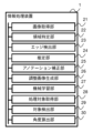
- FIG. 2 is a diagram showing an outline of the functional configuration of the information processing device 1 according to this embodiment.
- a program recorded in the storage device 14 is read out to the RAM 13 and executed by the CPU 11 to control each hardware provided in the information processing apparatus 1, whereby the image acquisition unit 21, information including a region identification unit 22, an edge detection unit 23, an estimation unit 24, an annotation correction unit 25, an adjusted image generation unit 26, a machine learning unit 27, a processing target acquisition unit 28, a target detection unit 29, and an angle calculation unit 30 It functions as a processor.
- each function of the information processing apparatus 1 is executed by the CPU 11, which is a general-purpose processor. It may be executed by a processor.
- the image acquisition unit 21 is an image used as teacher data for machine learning, and one or more annotations for indicating the position where a predetermined target (antenna device in this embodiment) is shown in the image. Get the image with .
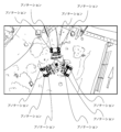
- FIG. 3 is a diagram showing an example of an annotated image used as teacher data according to the present embodiment.
- the training data is used for detecting an antenna device for a mobile phone network installed on a structure such as an outdoor utility pole or steel tower from an image obtained by aerial photography using a flying drone 8. Used to generate and/or update learning models. For this reason, the image is annotated in advance to indicate the position of the antenna device.
- the antenna device is configured in an image obtained by looking down from the sky (in a substantially vertical direction) on the antenna device installed on the pole of the base station.
- a plurality of dots are attached as annotations to the contours of the three box-shaped members (in other words, the boundary between the antenna device and the background) (the positions of the dots are indicated by circles in FIG. the annotated position is the center of the circle).
- the annotation is attached as a point indicating the position in the image.
- the expression form of the annotation is not limited.
- Annotations may be, for example, straight lines, curves, figures, fills, etc. added to an image.
- the area identifying unit 22 identifies areas in the image where one or more annotations satisfy a predetermined criterion. At least one of the density of annotations, the position of annotations, the positional relationship between annotations, and the arrangement of annotations in an image can be used as the predetermined criteria. For example, the region identifying unit 22 may identify regions in the image where the amount of annotations relative to the area satisfies a predetermined criterion. Also, for example, the region identifying unit 22 may identify a region where the positions of a plurality of annotations have a predetermined relationship.
- FIG. 4 is a diagram showing areas that meet predetermined criteria specified in an image in this embodiment. According to the example shown in FIG. 4, by specifying a region where one or more annotations, not the entire image, satisfies a predetermined criterion, the region to be subjected to edge detection, which will be described later, is limited. It can be seen that the processing load for edge detection can be reduced compared to the case where edge detection is performed on the entire image.
- the method for identifying the area is not limited here, specific methods for identifying the area are exemplified below.
- the area specifying unit 22 determines the area formed by connecting these annotations.
- a center of gravity and an area where the density of these annotations does not fall below a predetermined density are calculated, and a region including the center of gravity and having the area is set so as to be the center, for example. By doing so, it is possible to specify a region where the amount of annotations relative to the area satisfies a predetermined standard.
- the region specifying unit 22 sets a circumscribing rectangle containing these annotations for each combination of some or all of the annotations in the image, and defines this rectangular region by the area of the rectangle and the number of annotations.
- the method exemplified above is an example of a method for specifying a region, and the region may be any as long as the amount of annotation with respect to the area satisfies a predetermined standard, and other specific methods are used to specify the region. may be adopted.
- the region specifying unit 22 specifies the positional relationship of the annotations included in the combination.
- each of the three box-shaped members that constitute the antenna device, which is a predetermined target according to the present embodiment has a substantially polygonal shape in which each side has a predetermined length relationship (ratio) in plan view (Fig. In the example shown, it has the shape of a square. For this reason, the region specifying unit 22 determines the number of annotations included in each combination of annotations that is the same as the number of vertices of the polygon (4 in the example shown in FIG. 4).
- a predetermined area can be identified by determining whether or not has a positional relationship as vertices of a substantially polygon having a predetermined length relationship (ratio). Further, for example, for each combination of annotations, a predetermined region may be specified by determining whether straight lines formed by a plurality of annotations are substantially parallel or substantially orthogonal to each other.
- the method exemplified above is an example of a method for specifying a region, and the region may be any one in which the positions of annotations related to the region have a predetermined relationship. method may be adopted.
- an example of specifying a rectangular area has been described, but the shape of the area is not limited, and may be circular, for example.
- the edge detection unit 23 preferentially performs edge detection in the specified area or a range set based on the area. That is, the edge detection unit 23 may use the area identified by the area identification unit 22 as it is, or set a different range based on the area (for example, set a margin), and use this range to good too.
- an appropriate one may be selected from conventionally used edge detection methods and edge detection methods devised in the future, and therefore description thereof is omitted.
- Conventionally known edge detection methods include, for example, the gradient method, the Sobel method, the Laplacian method, the Canny method, and the like, but the edge detection methods that can be used and the filters that can be used are not limited.
- the estimation unit 24 estimates the intended position of the annotation based on the detected edges.
- the estimation unit 24 estimates the intended position of the annotation by referring to edges detected around the position of the annotation. More specifically, for example, the estimating unit 24 may estimate the position closest to the annotation among the edges detected in the region as the intended position of the annotation. Also, for example, the estimating unit 24 may estimate a position having a predetermined characteristic among the edges detected in the region as the intended position of the annotation.
- examples of the position having a predetermined characteristic include a position where edge lines intersect, a position where edge lines form an angle, a position where edge lines have a predetermined shape, and the like.
- the annotation correction unit 25 corrects the annotation along the detected edge by moving the position of the annotation to the position estimated by the estimation unit 24 .
- the position estimated by the estimation unit 24 is, for example, the position closest to the annotation among the edges detected in the region, the position where the lines of the edges intersect, the position where the lines of the edges form an angle, or a position where the edge line has a predetermined shape, and so on.
- the position of the annotation can be corrected to the outline of the predetermined object in the image (in other words, the boundary with the background) that was originally intended by the annotator.
- FIG. 5 is a diagram showing an example of an image whose annotations have been corrected in this embodiment. According to the example shown in FIG. 5, the position of the annotation that was deviated from the edge in FIG. 3 is corrected, and the contour (in other words, the It can be seen that the annotation is correctly attached to the boundary with the background).
- the adjusted image generation unit 26 generates an adjusted image in which image parameters are adjusted.
- the adjusted image generation unit 26 generates an adjusted image in which the parameters of the image are adjusted so that the detection of the predetermined target becomes difficult.
- a predetermined target for example, pixels in which a predetermined target (antenna device in this embodiment) is imaged and the background of the predetermined target (for example, the ground, buildings, such that the parameters of each pixel are similar to or the same as the pixels in which plants, structures on the ground, etc. are imaged (in other words, the color of the predetermined target is a protective color against the background color).
- the adjusted image generation unit 26 sets parameters related to at least one of image brightness, exposure, white balance, hue, saturation, lightness, sharpness, noise, contrast, and the like. An adjusted adjusted image may be generated.
- the adjusted image generation unit 26 may generate a plurality of mutually different adjusted images based on one image. That is, the adjusted image generation unit 26 generates a first adjusted image whose image parameters are adjusted and a second adjusted image whose image parameters are adjusted so as to be different from those of the first adjusted image. good.
- the plurality of adjusted images generated include adjusted images in which the same type of parameters are adjusted to different degrees and/or adjusted images in which different types of parameters are adjusted. good.
- the same plurality of annotations may be attached to each of the plurality of adjusted images.
- the annotation may be the annotation corrected via edge detection of the one image, or the annotation corrected via edge detection of any adjusted image.
- the edge detection section 23 may perform edge detection on the adjusted image generated by the adjusted image generation section 26 .
- the estimation unit 24 may estimate the position closest to the annotation among the edges detected in the adjusted image as the intended position of the annotation.
- the position closest to the annotation is regarded as the annotation. may be assumed as the intended position.
- the machine learning unit 27 performs machine learning using teacher data including the image corrected by the annotation correction unit 25 and/or the adjusted image to create a learning model for detecting a predetermined target in the image. Generate. For example, in the present embodiment, learning model generation for detecting a predetermined target in an image is illustrated using supervised machine learning using the PyTorch library, as illustrated in the angle calculation unit 30 to be described later. (See Non-Patent Document 1). However, for the machine learning, an appropriate one may be selected from conventionally used machine learning algorithms and machine learning algorithms devised in the future, and therefore the description thereof is omitted.
- the image used as teacher data by the machine learning unit 27 may be an image to which one or more annotations are added to indicate the position where a predetermined target is shown in the image.
- the type of image that can be used is not limited.
- the machine learning unit 27 converts the image as it is acquired by the image acquisition unit 21, the image corrected by the annotation correction unit 25, the adjusted image generated by the adjusted image generation unit 26, and the image corrected by the annotation correction unit 25.
- An adjusted image generated by the adjusted image generating unit 26 based on the above can be used as teacher data.
- the adjusted image a plurality of different adjusted images generated based on one image, that is, teacher data including a first adjusted image and a second adjusted image may be used. Note that the same multiple annotations may be attached to each of the image and the adjusted image used as teacher data.
- the processing target acquisition unit 28 acquires the processing target image.
- the image to be processed is an image taken from the air using the imaging device 81 mounted on the drone 8 during flight.
- the image to be processed may be an image in which a predetermined target is desired to be detected, and may be an RGB image or a depth image, and the type of image to be processed is not limited.
- the object detection unit 29 uses the learning model generated by the machine learning unit 27 for detecting the prescribed object in the image to detect the prescribed object in the image to be processed.
- the object detection unit 29 detects an antenna device installed outdoors as a predetermined object in the image to be processed.
- the object detection unit 29 can detect various objects from the image according to the image used as teacher data and the object of the annotation. type is not limited.
- the detected predetermined target is usually specified by the same method as the annotation attached to the teacher data. That is, if the annotation is a point indicating the contour of a predetermined target, the target detection unit 29 identifies the predetermined target in the processing target image by adding points to the contour of the predetermined target.
- the method of specifying the predetermined target is not limited, and it may be specified by a method different from the annotation.
- the angle calculation unit 30 calculates the angle of the detected target with respect to a predetermined reference in the image to be processed. More specifically, in the present embodiment, the angle calculator 30 calculates the angle of the detected object with respect to a predetermined direction, the vertical direction, or the horizontal direction in the image to be processed.
- the method for calculating the angle by the angle calculation unit 30 is not limited, but for example, detection by a machine learning model (see Non-Patent Document 1) or detection by comparison with a predefined target shape is used. A method of detecting the direction of the target using a method of calculating the angle formed by the detected direction of the target and the reference direction in the image to be processed may be adopted.
- the user In executing the annotation correction processing, data augmentation processing, and machine learning processing described below, the user prepares teacher data including images with annotations in advance.
- a plurality of images including an image showing an antenna device are obtained.
- the plurality of images may include an image in which the antenna device is not shown.
- teacher data is created.
- the work of annotating the image may be manually performed by the annotator or may be automatically performed. The details of the process of annotating an image will be omitted because conventional annotation support techniques may be employed.
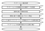
- FIG. 6 is a flowchart showing the flow of annotation correction processing according to this embodiment. The processing shown in this flowchart is executed when training data including images with annotations is prepared and the user inputs an annotation correction instruction.
- step S101 teacher data including images with annotations are acquired.
- the image acquisition unit 21 acquires, as training data, an image to which one or more annotations are added to indicate the position of a predetermined target (antenna device in this embodiment) in the image. After that, the process proceeds to step S102.
- steps S102 and S103 regions where one or more annotations satisfy predetermined criteria are identified, and edges are detected in the identified regions.
- the region identifying unit 22 identifies regions in the image in the teacher data obtained in step S101 where one or more annotations satisfy a predetermined standard (step S102). Then, the edge detection unit 23 performs edge detection in the area specified in step S102 or the range set based on the area (step S103). After that, the process proceeds to step S104.
- the annotation is corrected along the detected edge.
- the estimation unit 24 estimates the intended position of the annotation based on the edges detected in step S103 (step S104). Then, the annotation correction unit 25 corrects the annotation along the detected edge by moving the position of the annotation to the position estimated in step S104 (step S105). After that, the processing shown in this flowchart ends.
- annotation correction processing it is possible to improve the efficiency of correction processing of annotations attached to images used as teacher data for machine learning, and to correct annotations with less processing load than before. becomes.
- FIG. 7 is a flowchart showing the flow of data extension processing according to this embodiment. The processing shown in this flow chart is executed when teacher data including images with annotations is prepared and the user inputs an instruction to expand the data.
- step S201 teacher data including images with annotations are acquired.
- the image acquisition unit 21 acquires, as training data, an image to which one or more annotations are added to indicate the position of a predetermined target (antenna device in this embodiment) in the image.
- the image with annotations acquired here is preferably an image to which annotation correction has been applied by the annotation correction processing described with reference to FIG. may After that, the process proceeds to step S202.
- steps S202 and S203 one or more adjusted images are generated.
- the adjusted image generation unit 26 generates an adjusted image in which the parameters of the image acquired in step S201 are adjusted (step S202).
- step S203 it is determined whether or not the generation of the adjusted image of all preset patterns for the image acquired in step S201 is completed (step S203), and if not completed (step NO in S203), the process returns to step S202. That is, the adjusted image generation unit 26 repeats the process of step S202 while changing the content of the parameter adjustment based on the one image obtained in step S201 to generate a plurality of mutually different adjusted images.
- the processing shown in this flowchart ends.
- FIG. 8 is a flowchart showing the flow of machine learning processing according to this embodiment. The processing shown in this flowchart is executed when teacher data including images with annotations is prepared and a machine learning instruction is input by the user.
- step S301 teacher data including images with annotations are acquired.
- the image acquisition unit 21 acquires, as training data, an image to which one or more annotations are added to indicate the position of a predetermined target (antenna device in this embodiment) in the image.
- the annotated image acquired here is an image to which annotation correction has been applied by the annotation correction processing described with reference to FIG. 6 and/or an image generated by the data augmentation processing described with reference to FIG. It is preferable that the adjusted image is an adjusted image, but an image that has undergone neither annotation correction nor parameter adjustment may be acquired. After that, the process proceeds to step S302.
- step S302 a learning model is generated or updated.
- the machine learning unit 27 performs machine learning using the teacher data including the image acquired in step S301, thereby creating a learning model for detecting a predetermined target (the antenna device in this embodiment) in the image. or update an existing learning model. After that, the processing shown in this flowchart ends.
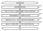
- FIG. 9 is a flowchart showing the flow of state determination processing according to this embodiment. The process shown in this flowchart is executed when the image data of the image to be processed is prepared and the user inputs a state determination instruction.
- the user uses the imaging device 81 of the flying drone 8 to capture an image of the antenna device of the base station, and inputs the image data of the obtained image to be processed to the information processing device 1 .
- the user may shoot such that a plurality of antenna devices are included in one processing target image.
- the state determination process is performed for each region of the antenna devices included in the processing target image.
- the imaging method and the method of inputting the image data to the information processing apparatus 1 are not limited, but in the present embodiment, the antenna device installed in the structure is imaged using the drone 8 equipped with the imaging device 81, and the imaging device 81 is used.
- the image data transferred from 81 to the user terminal 9 via communication or a recording medium is further transferred to the information processing apparatus 1 via the network, thereby inputting the image data of the processing target image to the information processing apparatus 1. .
- a predetermined target in the processing target image is detected using the learning model.
- the processing target acquiring unit 28 acquires a processing target image (in this embodiment, an image captured by an aerial photograph using the imaging device 81 mounted on the flying drone 8) (step S401).
- the target detection unit 29 uses the learning model generated by the machine learning process described with reference to FIG. 8 to detect a predetermined target (in this embodiment, an antenna device) is detected (step S402). After that, the process proceeds to step S403.
- step S403 and S404 the inclination of the detected object is calculated.
- the angle calculator 30 calculates the angle of the object detected in step S402 with respect to a predetermined reference in the image to be processed.
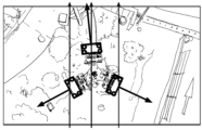
- FIG. 10 is a diagram showing an overview of azimuth calculation in a top-view image to be processed in this embodiment.
- FIG. 10 shows that the angle calculation unit 30 detects that the direction of the antenna device (predetermined target) detected from the processing target image is the north direction (either true north or magnetic north) that is a predetermined reference. good) is shown.
- the angle calculation unit 30 determines a reference direction (here, north direction) in the processing target image (step S403).
- the image to be processed is preliminarily corrected so that the direction directly above the image is the north direction, and the direction directly above the image is determined as the reference direction.
- the reference direction may be determined by other methods.
- the image to be processed is not an image that has been corrected so that the top direction of the image is the north direction
- metadata attached to the image to be processed acceleration of each axis, angular velocity of each axis, position Information, direction, etc.
- a method of comparing the image to be processed and the map image to specify the north direction in the image and determine the north direction as the reference direction.
- a direction other than the north direction may be adopted as the reference direction.
- an installation direction, a vertical direction, a horizontal direction, or the like, which is correct in terms of design of a predetermined target (antenna device in this embodiment) may be adopted.
- the angle calculation unit 30 determines the orientation of the detected antenna device (predetermined target) (step S404).
- the method for determining the orientation of the predetermined target by the angle calculation unit 30 is not limited. By reading a method of estimating the direction (see Non-Patent Document 2) or a combination of a predefined shape of the antenna device and the front direction of the antenna device in that shape, and applying it to the contour of the detected antenna device, A method of determining the front direction of the detected antenna device, etc. may be employed. Then, the angle calculator 30 calculates the angle formed by the determined reference direction and the determined front direction of the antenna device. In the example shown in FIG.
- the angle between the reference direction indicated by the thin arrowed line and the front direction of the antenna device indicated by the thick arrowed line is calculated.
- the reference direction may be the orientation, the installation direction, the vertical direction, the horizontal direction, etc., which are correct in terms of the design of the predetermined target.
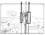
- FIG. 11 is a diagram showing an outline of calculation of the tilt of the side-view image to be processed in this embodiment.
- FIG. 11 shows an outline of a case where the angle calculation unit 30 calculates the angle formed by the inclination of the antenna device (predetermined target) detected from the processing target image with respect to the vertical direction, which is a predetermined reference. .
- the angle calculator 30 determines a reference direction (here, the vertical direction) in the image to be processed (step S403).
- a reference direction here, the vertical direction
- the reference direction may be determined by other methods.
- the vertical direction in the image may be specified by referring to metadata (acceleration of each axis, angular velocity of each axis, etc.) attached to the image to be processed, and the vertical direction may be determined as the reference direction.
- the angle calculation unit 30 can calculate the azimuth (azimuth), tilt (tilt), and the like of a predetermined target. After that, the process proceeds to step S405.
- step S405 the state of the predetermined target is determined.
- the information processing apparatus 1 determines whether or not the angle calculated in step S404 is within a predetermined range set in advance, thereby determining whether or not the installation state of the antenna device is correct. determine whether After that, the processing shown in this flowchart ends, and the determination result is output to the user.
- the angle of the predetermined target with respect to the reference direction can be obtained, and by referring to the obtained angle, the state of the predetermined target (in this embodiment, the installation state) can be determined.
- annotation correction processing data extension processing, machine learning processing, and state determination processing are executed in one information processing apparatus. It may be performed by an apparatus. At this time, the image acquiring unit 21, the area specifying unit 22, the edge detecting unit 23, the estimating unit 24, the annotation correcting unit 25, the adjusted image generating unit 26, the machine learning unit 27, and the processing target acquiring unit included in the information processing apparatus 1 28, the object detection unit 29 and the angle calculation unit 30 may be partially omitted.
- FIG. 12 is a diagram showing an outline of the functional configuration of the information processing device 1b according to the variation.
- the information processing device 1b includes an image acquisition unit 21, a region identification unit 22, an edge detection unit 23, an estimation unit 24, an annotation correction unit 25, a machine learning unit 27, a processing target acquisition unit 28, and a target detection unit 29.
- function as Each function provided in the information processing apparatus 1b is substantially the same as that of the embodiment described above except that the adjusted image generation unit 26 and the angle calculation unit 30 are omitted, so description thereof will be omitted.
- FIG. 13 is a diagram showing an outline of the functional configuration of the information processing device 1c according to the variation.
- the information processing device 1 c functions as an information processing device including an adjusted image generation unit 26 , a machine learning unit 27 , a processing target acquisition unit 28 and a target detection unit 29 .
- Each function provided in the information processing apparatus 1c has been described above except that the image acquisition unit 21, the region identification unit 22, the edge detection unit 23, the estimation unit 24, the annotation correction unit 25, and the angle calculation unit 30 are omitted. Since it is substantially the same as the embodiment, the description is omitted.
Landscapes
- Engineering & Computer Science (AREA)
- Theoretical Computer Science (AREA)
- Physics & Mathematics (AREA)
- General Physics & Mathematics (AREA)
- Multimedia (AREA)
- Computer Vision & Pattern Recognition (AREA)
- Evolutionary Computation (AREA)
- Computational Linguistics (AREA)
- Health & Medical Sciences (AREA)
- Artificial Intelligence (AREA)
- Computing Systems (AREA)
- Databases & Information Systems (AREA)
- General Health & Medical Sciences (AREA)
- Medical Informatics (AREA)
- Software Systems (AREA)
- Geometry (AREA)
- Image Analysis (AREA)
- Image Processing (AREA)
Abstract
Description
図1は、本実施形態に係るシステムの構成を示す概略図である。本実施形態に係るシステムは、ネットワークに接続されることで互いに通信可能な情報処理装置1と、ドローン8と、ユーザ端末9とを備える。
次に、本実施形態に係る情報処理装置1によって実行される処理の流れを説明する。なお、以下に説明する処理の具体的な内容及び処理順序は、本開示を実施するための一例である。具体的な処理内容及び処理順序は、本開示の実施の形態に応じて適宜選択されてよい。
上記説明した実施形態では、アノテーション補正処理、データ拡張処理、機械学習処理及び状態判定処理を1の情報処理装置において実行する例について説明したが、これらの処理は夫々が分離されて別個の情報処理装置によって実行されてもよい。また、この際、情報処理装置1が備える画像取得部21、領域特定部22、エッジ検出部23、推定部24、アノテーション補正部25、調整画像生成部26、機械学習部27、処理対象取得部28、対象検出部29及び角度算出部30は、その一部が省略されてよい。
Claims (19)
- 機械学習のための教師データとして用いられる画像であって、画像中の所定の対象が示された位置を示すための1又は複数のアノテーションが付された画像を取得する画像取得手段と、
前記画像における、前記1又は複数のアノテーションが所定の基準を満たす領域を特定する領域特定手段と、
特定された前記領域又は該領域に基づいて設定された範囲において優先的にエッジ検出を行うエッジ検出手段と、
前記アノテーションを、検出された前記エッジに沿うように補正するアノテーション補正手段と、
を備える情報処理装置。 - 前記領域特定手段は、前記画像における、面積に対するアノテーションの量が所定の基準を満たす領域を特定する、
請求項1に記載の情報処理装置。 - 前記領域特定手段は、複数のアノテーションの位置が所定の関係にある領域を特定する、
請求項1又は2に記載の情報処理装置。 - 検出された前記エッジに基づいて、前記アノテーションが意図されていた位置を推定する推定手段を更に備え、
前記アノテーション補正手段は、前記アノテーションの位置を、前記推定手段によって推定された位置に移動させる、
請求項1から3のいずれか一項に記載の情報処理装置。 - 前記アノテーション補正手段は、前記アノテーションの位置を、該アノテーションに最も近いエッジの位置に移動させる、
請求項1から4のいずれか一項に記載の情報処理装置。 - 前記アノテーション補正手段によって補正された画像を含む教師データを用いた機械学習を実行することで、画像中の前記所定の対象を検出するための学習モデルを生成する機械学習手段を更に備える、
請求項1から5のいずれか一項に記載の情報処理装置。 - 処理対象画像を取得する処理対象取得手段と、
前記機械学習手段によって生成された学習モデルを用いて前記処理対象画像中の前記所定の対象を検出する対象検出手段と、
を更に備える、請求項6に記載の情報処理装置。 - 検出された対象の、前記処理対象画像における所定の基準に対する角度を算出する角度算出手段を更に備える、
請求項7に記載の情報処理装置。 - 前記角度算出手段は、検出された対象の、前記処理対象画像における所定の方角、鉛直方向及び水平方向のいずれかに対する角度を算出する、
請求項8に記載の情報処理装置。 - 処理対象画像を取得する処理対象取得手段と、
画像中の所定の対象が示された位置を示すための1又は複数のアノテーションが付された画像を含む教師データを用いた機械学習によって生成された、画像中の前記所定の対象を検出するための学習モデルを用いて前記処理対象画像中の前記所定の対象として、屋外に設置されたアンテナ装置を検出する対象検出手段と、
検出された対象の、前記処理対象画像における所定の基準に対する角度を算出する角度算出手段と、
を備える情報処理装置。 - 前記所定の対象が示された位置を示すための1又は複数のアノテーションが付された画像を取得する画像取得手段と、
前記画像中のエッジ検出を行うエッジ検出手段と、
前記アノテーションを、検出された前記エッジに沿うように補正するアノテーション補正手段と、
前記アノテーション補正手段によって補正された画像を含む教師データを用いた前記機械学習を実行することで、前記学習モデルを生成する機械学習手段と、
を更に備える、請求項10に記載の情報処理装置。 - 前記画像における、前記1又は複数のアノテーションが所定の基準を満たす領域を特定する領域特定手段を更に備え、
前記エッジ検出手段は、特定された前記領域又は該領域に基づいて設定された範囲において優先的にエッジ検出を行う、
請求項11に記載の情報処理装置。 - 前記領域特定手段は、前記画像における、面積に対するアノテーションの量が所定の基準を満たす領域を特定する、
請求項12に記載の情報処理装置。 - 前記領域特定手段は、複数のアノテーションの位置が所定の関係にある領域を特定する、
請求項12又は13に記載の情報処理装置。 - 検出された前記エッジに基づいて、前記アノテーションが意図されていた位置を推定する推定手段を更に備え、
前記アノテーション補正手段は、前記アノテーションの位置を、前記推定手段によって推定された位置に移動させる、
請求項11から14のいずれか一項に記載の情報処理装置。 - 前記アノテーション補正手段は、前記アノテーションの位置を、該アノテーションに最も近いエッジの位置に移動させる、
請求項11から15のいずれか一項に記載の情報処理装置。 - 前記角度算出手段は、検出された対象の、前記処理対象画像における所定の方角、鉛直方向及び水平方向のいずれかに対する角度を算出する、
請求項10から16のいずれか一項に記載の情報処理装置。 - コンピュータが、
機械学習のための教師データとして用いられる画像であって、画像中の所定の対象が示された位置を示すための1又は複数のアノテーションが付された画像を取得する画像取得ステップと、
前記画像における、前記1又は複数のアノテーションが所定の基準を満たす領域を特定する領域特定ステップと、
特定された前記領域又は該領域に基づいて設定された範囲において優先的にエッジ検出を行うエッジ検出ステップと、
前記アノテーションを、検出された前記エッジに沿うように補正するアノテーション補正ステップと、
を実行する方法。 - コンピュータが、
処理対象画像を取得する処理対象取得ステップと、
画像中の所定の対象が示された位置を示すための1又は複数のアノテーションが付された画像を含む教師データを用いた機械学習によって生成された、画像中の前記所定の対象を検出するための学習モデルを用いて前記処理対象画像中の前記所定の対象として、屋外に設置されたアンテナ装置を検出する対象検出ステップと、
検出された対象の、前記処理対象画像における所定の基準に対する角度を算出する角度算出ステップと、
を実行する方法。
Priority Applications (3)
| Application Number | Priority Date | Filing Date | Title |
|---|---|---|---|
| JP2022580891A JP7457844B2 (ja) | 2021-12-27 | 2021-12-27 | 情報処理装置及び方法 |
| US18/003,385 US20240104880A1 (en) | 2021-12-27 | 2021-12-27 | Information processing apparatus and method |
| PCT/JP2021/048570 WO2023127019A1 (ja) | 2021-12-27 | 2021-12-27 | 情報処理装置及び方法 |
Applications Claiming Priority (1)
| Application Number | Priority Date | Filing Date | Title |
|---|---|---|---|
| PCT/JP2021/048570 WO2023127019A1 (ja) | 2021-12-27 | 2021-12-27 | 情報処理装置及び方法 |
Publications (1)
| Publication Number | Publication Date |
|---|---|
| WO2023127019A1 true WO2023127019A1 (ja) | 2023-07-06 |
Family
ID=86998322
Family Applications (1)
| Application Number | Title | Priority Date | Filing Date |
|---|---|---|---|
| PCT/JP2021/048570 Ceased WO2023127019A1 (ja) | 2021-12-27 | 2021-12-27 | 情報処理装置及び方法 |
Country Status (3)
| Country | Link |
|---|---|
| US (1) | US20240104880A1 (ja) |
| JP (1) | JP7457844B2 (ja) |
| WO (1) | WO2023127019A1 (ja) |
Citations (4)
| Publication number | Priority date | Publication date | Assignee | Title |
|---|---|---|---|---|
| JP2019056966A (ja) * | 2017-09-19 | 2019-04-11 | 株式会社東芝 | 情報処理装置、画像認識方法および画像認識プログラム |
| JP2020119515A (ja) * | 2019-01-25 | 2020-08-06 | 株式会社ベーシック | 設置物認識システム及びそのプログラム |
| WO2020204051A1 (ja) * | 2019-04-02 | 2020-10-08 | 富士フイルム株式会社 | 画像処理装置とその作動方法および作動プログラム、運用装置とその作動方法および作動プログラム、並びに機械学習システム |
| JP2021077921A (ja) * | 2019-10-31 | 2021-05-20 | Necネッツエスアイ株式会社 | アンテナ施工補助方法 |
-
2021
- 2021-12-27 WO PCT/JP2021/048570 patent/WO2023127019A1/ja not_active Ceased
- 2021-12-27 JP JP2022580891A patent/JP7457844B2/ja active Active
- 2021-12-27 US US18/003,385 patent/US20240104880A1/en active Pending
Patent Citations (4)
| Publication number | Priority date | Publication date | Assignee | Title |
|---|---|---|---|---|
| JP2019056966A (ja) * | 2017-09-19 | 2019-04-11 | 株式会社東芝 | 情報処理装置、画像認識方法および画像認識プログラム |
| JP2020119515A (ja) * | 2019-01-25 | 2020-08-06 | 株式会社ベーシック | 設置物認識システム及びそのプログラム |
| WO2020204051A1 (ja) * | 2019-04-02 | 2020-10-08 | 富士フイルム株式会社 | 画像処理装置とその作動方法および作動プログラム、運用装置とその作動方法および作動プログラム、並びに機械学習システム |
| JP2021077921A (ja) * | 2019-10-31 | 2021-05-20 | Necネッツエスアイ株式会社 | アンテナ施工補助方法 |
Also Published As
| Publication number | Publication date |
|---|---|
| JP7457844B2 (ja) | 2024-03-28 |
| US20240104880A1 (en) | 2024-03-28 |
| JPWO2023127019A1 (ja) | 2023-07-06 |
Similar Documents
| Publication | Publication Date | Title |
|---|---|---|
| CN110148185B (zh) | 确定成像设备坐标系转换参数的方法、装置和电子设备 | |
| CN111815707B (zh) | 点云确定方法、点云筛选方法、装置、计算机设备 | |
| US20220270323A1 (en) | Computer Vision Systems and Methods for Supplying Missing Point Data in Point Clouds Derived from Stereoscopic Image Pairs | |
| WO2021035731A1 (zh) | 无人飞行器的控制方法、装置及计算机可读存储介质 | |
| EP4068210B1 (en) | System and method for automated estimation of 3d orientation of a physical asset | |
| CN119478297B (zh) | 一种基于5g飞控的实时三维建模方法、系统及介质 | |
| CN114004977A (zh) | 一种基于深度学习的航拍数据目标定位方法及系统 | |
| JP2022514429A (ja) | 画像収集機器のキャリブレーション方法、装置、システム、機器及び記憶媒体 | |
| KR102935591B1 (ko) | 모바일 환경에서 단일 이미지 객체 인식 기반의 시각적 측위 방법 및 장치 | |
| WO2021056139A1 (zh) | 获取降落位置的方法、设备、无人机、系统及存储介质 | |
| CN109978997A (zh) | 一种基于倾斜影像的输电线路三维建模方法和系统 | |
| KR20240022986A (ko) | 카메라 포즈 정보와 장면 이전 정보의 융합을 이용하여유클리드 공간 내의 객체들의 거리를 추정하는 방법 및 장치 | |
| CN115836322B (zh) | 图像裁剪方法与装置、电子设备及存储介质 | |
| CN111104861B (zh) | 用于确定电线位置的方法和设备以及存储介质 | |
| CN111062875B (zh) | 一种用于空中全景漫游数据的坐标转换方法及装置 | |
| JP7734233B2 (ja) | 情報処理装置及び方法 | |
| JP7457844B2 (ja) | 情報処理装置及び方法 | |
| CN120147421A (zh) | 无人机的空间位姿识别方法、装置、设备和介质 | |
| CN117173238B (zh) | 一种无人机编队相对定位方法 | |
| JP7585358B2 (ja) | 情報処理システム、方法及びプログラム | |
| CN114926332B (zh) | 基于无人机母车的无人机全景图像拼接方法 | |
| CN110852988A (zh) | 一种绝缘子串自爆的检测方法、装置、设备及存储介质 | |
| CN119598676B (zh) | 模板化光伏电站设计方法、设备、介质及产品 | |
| CN115984456B (zh) | 一种纹理贴图的方法、装置、电子设备及存储介质 | |
| KR20260064170A (ko) | 카메라와 라이다 센서 기반 실시간 캘리브레이션 틀어짐 감지 및 자동 교정 방법 및 장치 |
Legal Events
| Date | Code | Title | Description |
|---|---|---|---|
| WWE | Wipo information: entry into national phase |
Ref document number: 18003385 Country of ref document: US Ref document number: 2022580891 Country of ref document: JP |
|
| 121 | Ep: the epo has been informed by wipo that ep was designated in this application |
Ref document number: 21969903 Country of ref document: EP Kind code of ref document: A1 |
|
| NENP | Non-entry into the national phase |
Ref country code: DE |
|
| 122 | Ep: pct application non-entry in european phase |
Ref document number: 21969903 Country of ref document: EP Kind code of ref document: A1 |