WO2023119751A1 - 画像処理装置、画像処理方法、及びプログラム - Google Patents
画像処理装置、画像処理方法、及びプログラム Download PDFInfo
- Publication number
- WO2023119751A1 WO2023119751A1 PCT/JP2022/034500 JP2022034500W WO2023119751A1 WO 2023119751 A1 WO2023119751 A1 WO 2023119751A1 JP 2022034500 W JP2022034500 W JP 2022034500W WO 2023119751 A1 WO2023119751 A1 WO 2023119751A1
- Authority
- WO
- WIPO (PCT)
- Prior art keywords
- image data
- noise component
- unit
- infrared camera
- noise
- Prior art date
- Legal status (The legal status is an assumption and is not a legal conclusion. Google has not performed a legal analysis and makes no representation as to the accuracy of the status listed.)
- Ceased
Links
Images





Classifications
-
- G—PHYSICS
- G01—MEASURING; TESTING
- G01J—MEASUREMENT OF INTENSITY, VELOCITY, SPECTRAL CONTENT, POLARISATION, PHASE OR PULSE CHARACTERISTICS OF INFRARED, VISIBLE OR ULTRAVIOLET LIGHT; COLORIMETRY; RADIATION PYROMETRY
- G01J1/00—Photometry, e.g. photographic exposure meter
- G01J1/42—Photometry, e.g. photographic exposure meter using electric radiation detectors
-
- G—PHYSICS
- G01—MEASURING; TESTING
- G01J—MEASUREMENT OF INTENSITY, VELOCITY, SPECTRAL CONTENT, POLARISATION, PHASE OR PULSE CHARACTERISTICS OF INFRARED, VISIBLE OR ULTRAVIOLET LIGHT; COLORIMETRY; RADIATION PYROMETRY
- G01J1/00—Photometry, e.g. photographic exposure meter
- G01J1/42—Photometry, e.g. photographic exposure meter using electric radiation detectors
- G01J1/44—Electric circuits
-
- G—PHYSICS
- G01—MEASURING; TESTING
- G01J—MEASUREMENT OF INTENSITY, VELOCITY, SPECTRAL CONTENT, POLARISATION, PHASE OR PULSE CHARACTERISTICS OF INFRARED, VISIBLE OR ULTRAVIOLET LIGHT; COLORIMETRY; RADIATION PYROMETRY
- G01J5/00—Radiation pyrometry, e.g. infrared or optical thermometry
- G01J5/48—Thermography; Techniques using wholly visual means
-
- H—ELECTRICITY
- H04—ELECTRIC COMMUNICATION TECHNIQUE
- H04N—PICTORIAL COMMUNICATION, e.g. TELEVISION
- H04N23/00—Cameras or camera modules comprising electronic image sensors; Control thereof
- H04N23/60—Control of cameras or camera modules
-
- H—ELECTRICITY
- H04—ELECTRIC COMMUNICATION TECHNIQUE
- H04N—PICTORIAL COMMUNICATION, e.g. TELEVISION
- H04N25/00—Circuitry of solid-state image sensors [SSIS]; Control thereof
- H04N25/60—Noise processing, e.g. detecting, correcting, reducing or removing noise
-
- H—ELECTRICITY
- H04—ELECTRIC COMMUNICATION TECHNIQUE
- H04N—PICTORIAL COMMUNICATION, e.g. TELEVISION
- H04N5/00—Details of television systems
- H04N5/30—Transforming light or analogous information into electric information
- H04N5/33—Transforming infrared radiation
Definitions
- the present invention relates to an image processing device, an image processing method, and a program.
- Patent Documents 1 and 2 disclose infrared imaging devices.
- the infrared imaging apparatus disclosed in Patent Document 1 corrects variations in pixels using a plurality of preset correction coefficient data based on the environmental temperature measured by the temperature sensor, without updating the correction data.
- the infrared imaging device of Patent Document 2 captures an image with the shutter closed. The infrared imaging device detects response defective pixels from this image.
- Infrared sensors such as microbolometers used in infrared imaging devices are affected by temperature stress, etc., and their characteristics change over time.
- the reproducibility of the output characteristics of the infrared sensor with respect to the ambient temperature deteriorates, and it is difficult to appropriately correct pixel variations.
- the apparatus of Patent Document 2 detects a response defect, it is difficult to easily detect the defect. Therefore, it becomes difficult to perform appropriate processing.
- the present disclosure has been made in view of the above points, and provides an image processing apparatus, an image processing method, and a program capable of appropriately processing thermal image data even when the characteristics of an infrared sensor change over time. I will provide a.
- the image processing apparatus includes a thermal image data acquisition unit that acquires thermal image data captured by an infrared camera, and first thermal image data captured by the infrared camera with the shutter closed, A correcting unit that generates shutterless corrected image data by correcting based on the environmental temperature of the usage environment of the infrared camera and pre-obtained calibration data; A noise component extraction unit for extracting noise components, and a noise removal unit for removing the noise components of the second thermal image data captured by the infrared camera with the shutter open.
- the image processing method includes the steps of acquiring first thermal image data captured by an infrared camera with the shutter closed, and adjusting the ambient temperature of the environment in which the infrared camera is used and pre-acquired calibration data. generating shutterless corrected image data by correcting the first thermal image data based on the above; extracting temporally changing noise components contained in the shutterless corrected image data; and removing noise components from second thermal image data captured by the infrared camera with the shutter open.
- a program according to the present embodiment is a program for causing a computer to execute an image processing method, the image processing method including the step of acquiring first thermal image data captured with the shutter of an infrared camera closed. generating shutterless corrected image data by correcting the first thermal image data based on the environmental temperature of the environment in which the infrared camera is used and previously obtained calibration data; and the shutterless corrected image data. and removing the noise component of the second thermal image data with the shutter open.
- An object of the present disclosure is to provide an image processing device, an image processing method, and a program capable of appropriately processing thermal image data from an infrared camera.
- FIG. 1 is a block diagram showing the configuration of an imaging system
- FIG. 1 is a block diagram showing the configuration of an infrared camera
- FIG. 3 is a block diagram showing the configuration of an image processing unit
- FIG. It is a block diagram which shows the structure of a NUC part.
- 4 is a flow chart showing an image processing method according to the first embodiment
- FIG. 8 is a block diagram showing the configuration of an image processing unit in Embodiment 2
- FIG. 4 is a diagram for explaining defective pixels appearing in noise components
- 9 is a flowchart showing an image processing method according to the second embodiment
- 9 is a flowchart showing an image processing method according to the second embodiment
- FIG. 12 is a block diagram showing the configuration of an image processing unit in Embodiment 3
- 10 is a flow chart showing an image processing method according to the third embodiment
- 11 is a flow chart showing an image processing method according to the third embodiment;
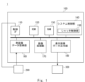
- FIG. 1 is a block diagram showing the configuration of an imaging system 1.
- the imaging system 1 includes an image processing device 100 , an infrared camera 200 and a display device 300 .
- the imaging system 1 is, for example, a vehicle imaging system that is used in a vehicle to obtain a thermal image of the surroundings, an imaging system that is used for monitoring purposes, or the like.
- the infrared camera 200 captures a thermal image (infrared image).
- the infrared camera 200 captures a thermal image by detecting far-infrared rays from a subject.
- the infrared camera 200 is a Far Infrared Rays (FIR) camera capable of visualizing far infrared rays emitted from an object.
- FIR Far Infrared Rays
- Data of a thermal image captured by the infrared camera 200 is also called thermal image data (or infrared image data).
- Thermal image data indicates the temperature distribution in the imaging range of infrared camera 200 .
- the infrared camera 200 outputs thermal image data to the image processing device 100 .
- Thermal image data input from the infrared camera 200 to the image processing apparatus 100 is also referred to as input thermal image data.
- Thermal image data indicates thermal image data captured by an infrared camera. A configuration of the infrared camera 200 will be described later.
- the image processing apparatus 100 generates display image data by performing image processing on input thermal image data. For example, the image processing apparatus 100 performs various processes such as correction of pixel variations of the infrared camera 200 and noise removal caused by changes in characteristics over time. By doing so, the temperature can be measured more accurately.
- the image processing device 100 outputs the image-processed display image data to the display device 300 .
- the display image data subjected to image processing by the image processing device 100 and output to the display device 300 is also referred to as output thermal image data.
- the input thermal image data is data before processing by the image processing apparatus 100
- the output thermal image data is data after processing.
- the display device 300 includes a liquid crystal display or the like for displaying display image data.
- the display device 300 displays display image data that has undergone image processing in the image processing device 100 . Thereby, the display device 300 can display a more accurate temperature distribution.
- the image processing apparatus 100 includes a control IF (interface) 110, a ROM (Read Only Memory) 120, a RAM (Random Access Memory) 130, a system control section 140, a shutter control section 150, a thermal image data acquisition section 160, and an image processing section 170. , and a display image data output unit 180 .
- the thermal image data acquisition unit 160 acquires thermal image data captured by the infrared camera 200 .
- an IF interface for inputting thermal image data from the infrared camera 200 is provided.
- the interface between the thermal image data acquiring unit 160 and the infrared camera 200 may be wired connection or wireless connection.
- the ROM 120 stores control programs and various parameters for controlling the image processing apparatus 100 .
- the ROM 120 stores image processing programs executed by the image processing section 170 .
- the ROM 120 also stores a system control program executed by the system control unit 140 .
- the RAM 130 stores various programs and parameters used for their execution. Further, it stores calculation data and the like of the image processing unit 170 .
- the system control unit 140 controls the imaging system 1 as a whole.
- the system control unit 140 includes a processor such as a CPU (Central Processing Unit).
- the processor of the system control unit 140 can control the entire system by executing the control program.
- the system control unit 140 includes a shutter control unit 150.
- the shutter control unit 150 controls opening and closing of the shutter of the infrared camera 200 .
- the shutter control section 150 outputs a control signal for opening and closing the shutter.
- the control IF 110 is an interface for controlling the infrared camera 200.
- the shutter control unit 150 outputs control signals for opening and closing the infrared camera 200 via the control IF 110 .
- the image processing apparatus 100 can transmit various signals and data to the infrared camera 200 via the control IF 110 .
- the control IF 110 can receive various signals and data from the infrared camera 200 .
- the control IF 110 acquires the environmental temperature measured by the temperature sensor of the infrared camera 200 .
- the image processing unit 170 performs predetermined image processing on the thermal image data acquired by the thermal image data acquisition unit 160 .
- the image processing section 170 may include a processor or the like for executing an image processing program.
- the processor of the image processing unit 170 may be a general-purpose processor or a dedicated processor.
- the processor of the image processing unit 170 and the processor of the system control unit 140 may be common. Processing in the image processing unit 170 will be described later.
- Display image data is generated by the image processing unit 170 performing image processing on the input thermal image data.
- a display image data output unit 180 is an interface that outputs display image data to the display device 300 .
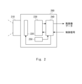
- FIG. 2 is a block diagram schematically showing the detailed configuration of the infrared camera 200.
- FIG. Infrared camera 200 comprises lens 210 , shutter 220 , sensor 230 , transmission device 240 and temperature sensor 250 .
- the lens 210 forms an image of the far-infrared light from the subject on the light receiving surface of the sensor 230 .
- Sensor 230 comprises a plurality of pixels. Each pixel of sensor 230 receives infrared light from a subject. Thereby, a thermal image of the subject can be captured.
- sensor 230 has a microbolometer for detecting far infrared radiation.
- Sensor 230 comprises a plurality of pixels arranged in a two-dimensional array. A detected value (detected signal) of each pixel forms a thermal image of the subject.
- the transmission device 240 serves as an interface for transmitting various signals and data to the image processing apparatus 100 .
- the transmission device 240 transmits thermal image data captured by the sensor 230 to the image processing apparatus 100 . Also, the transmission device 240 receives a control signal from the image processing apparatus 100 .
- the temperature sensor 250 measures the temperature in the usage environment of the infrared camera.
- the transmission device 240 transmits the environmental temperature measured by the temperature sensor 250 to the image processing apparatus 100 .
- the ambient temperature measured by the temperature sensor 250 is used for shutterless correction, which will be described later.
- the shutter 220 is arranged on the front side of the sensor 230 .
- the shutter 220 blocks infrared light entering the sensor 230 from the outside.
- the shutter 220 has an openable/closable mechanism.
- Shutter 220 opens and closes according to a control signal from shutter control section 150 . Outside light from the lens 210 does not enter the sensor 230 when the shutter 220 is closed (hereinafter also simply referred to as a closed state). That is, in the closed state, infrared light from the shutter 220 enters the sensor 230 . Infrared light from the lens 210 enters the sensor 230 when the shutter 220 is open (hereinafter also simply referred to as an open state).
- the shutter 220 can make the imaging range of the sensor 230 a thermal uniform surface.
- shutter 220 may be like a barrier or cover positioned in front of lens 210 .
- FIG. 3 is a block diagram showing the detailed configuration of the image processing section 170.
- the image processing unit 170 includes a defective pixel correction unit 171 , an NUC (Non-Uniformity Correction) unit 172 and a noise component extraction unit 173 .
- the image processing unit 170 cooperates with the system control unit 140 and the RAM 130 to execute predetermined processing.
- the defective pixel correction unit 171 interpolates the pixel values of the defective pixels of the sensor 230 stored in advance in the RAM 130 from the pixel values of the pixels surrounding the defective pixels.
- the defective pixel correction unit 171 performs the above-described interpolation processing on the input thermal image data acquired by the thermal image data acquisition unit 160 and outputs the image data that has undergone the interpolation processing to the NUC unit 172 .
- a NUC (Non-Uniformity Correction) unit 172 performs processing for correcting variations in output between pixels.
- a detailed configuration of the NUC unit 172 is shown in FIG.
- the NUC section 172 includes a correction section 177 and a noise elimination section 178 .
- the correction unit 177 performs shutterless correction on the input thermal image data based on the environmental temperature.
- Shutterless correction is, for example, correcting pixel variations of the sensor 230 without closing the shutter 220 using a plurality of correction values corresponding to the environmental temperature.
- pixel variations in the output of the sensor 230 are corrected using correction values based on pre-obtained calibration data.
- the infrared camera 200 or the image processing device 100 acquires a plurality of pieces of calibration data in advance and stores them in a memory or the like. For example, calibration data corresponding to seven different environmental temperatures are obtained in advance.
- the calibration data corresponding to the environmental temperature that have not been acquired in advance can be predicted by interpolation processing using approximate values obtained by approximating a plurality of calibration data that have been acquired in advance using a polynomial or the like.
- the sensor output of the sensor 230 varies in pixel variation depending on the environmental temperature. Therefore, when the sensor 230 receives infrared light, the pixel variation with respect to the ambient temperature at that time is corrected using calibration data acquired in advance.
- the correction unit 177 corrects pixel variations based on a plurality of pieces of calibration data obtained in advance without performing calibration using a shutter. Such correction is called shutterless correction.
- the thermal image data subjected to shutterless correction by the correction unit 177 is taken as shutterless corrected image data. That is, the shutterless corrected image data is thermal image data on which shutterless correction processing has been performed.
- the noise removal unit 178 removes noise generated in the shutterless corrected image data when the sensor characteristics change with time and the correction accuracy based on the pre-acquired calibration data deteriorates. The processing of the noise removal unit 178 will be described later.
- the noise component extraction unit 173 extracts noise components in the input thermal image data. Specifically, the noise component extraction unit 173 extracts noise components from the shutterless corrected image data with the shutter 220 closed. The noise component changes over time due to temperature stress of the sensor 230 or the like.
- the noise removal section 178 performs processing for removing the noise component extracted by the noise component extraction section 173 .
- the correction by the correction unit 177 can correct pixel variations at any environmental temperature by performing correction processing using calibration data obtained in advance.
- the noise component extraction unit 173 extracts the noise component generated over time for each pixel.
- the noise removal unit 178 removes noise components generated over time for each pixel.
- Isless (w, h) Pixel data after shutterless correction is hereinafter referred to as Isless (w, h).
- w is the horizontal pixel address and h is the vertical pixel address.
- n(w, h) be a noise component generated by a change over time.
- n(w, h) indicates a two-dimensional distribution of noise components.
- the shutterless correction output Iout(w, h) including noise components generated over time is expressed by the sum of Isless(w, h) and n(w, h) as shown in the following equation (1).
- Iout(w,h) Isless(w,h)+n(w,h) (1)
- the noise component n(w, h) generated in the shutterless-corrected image data also gradually increases. Therefore, the shutterless-corrected image quality also deteriorates over time.
- the noise component n(w, h) also includes newly generated defective pixel information.
- T0 is the ambient temperature measured by the temperature sensor 250 in the closed state. That is, T0 is the ambient temperature during the noise component extraction process.
- the noise component extraction unit 173 obtains the average value of Isless_T0(w, h) of all pixels.
- the noise component extraction unit 173 calculates a subtraction value obtained by subtracting the average value from Isless_T0(w, h) as a noise component.
- the noise component n(w, h) is shown in the following equation (2).
- W is the number of pixels in the horizontal direction
- H is the number of pixels in the vertical direction.
- the product of W and H indicates the total number of pixels of thermal image data.
- the second term on the right side is the pixel average value of Isless_T0(w, h). That is, the average value is obtained by dividing the total sum of Isless_T0(w, h) by the total number of pixels (W*sH).
- the noise component extraction unit 173 extracts the noise component n(w, h) by performing the above processing.
- the noise removal section 178 removes noise from the shutterless corrected image data in the open state.
- T is the environmental temperature.
- ⁇ is a coefficient and has a constant value.
- ⁇ may be a variable that changes according to environmental temperature or the like.
- ⁇ is common between pixels, it may be different for each pixel.
- the noise removal unit 178 generates noise-removed image data by performing noise removal processing on the shutterless corrected image data.
- the noise removal unit 178 outputs the noise-removed image data to the display image data output unit 180 (see FIG. 1).
- the display image data output unit 180 outputs the noise-removed image data to the display device 300 as output thermal image data.
- the image processing apparatus 100 can remove noise components that occur over time in the input thermal image data. Since the image processing apparatus 100 extracts the noise component from the thermal image data in the closed state, the noise component can be extracted with higher accuracy. Thereby, the measurement accuracy of the temperature distribution of the infrared camera 200 can be improved. Furthermore, the noise component extraction unit 173 may extract the noise component each time the thermal image data is captured in the closed state. This allows the noise component extraction unit 173 to repeatedly calculate the noise component. Therefore, even when the degree of change in characteristics over time differs for each pixel, appropriate processing can be performed.
- the correction unit 177 performs shutterless correction on the thermal image data captured in the closed state. Then, the noise component extraction unit 173 extracts the noise component based on the shutterless corrected image data in the closed state. This makes it possible to extract the noise component generated when the accuracy of correction based on calibration data obtained in advance deteriorates due to changes in the sensor 230 over time.
- the image processing device 100 stores the extracted noise components in a memory or the like and removes the noise components. Since noise components due to deterioration over time can be removed by simple processing, the processing load can be reduced.
- the noise component n(w, h) also includes information on defective pixels. By performing the noise component removal described above, it is possible to appropriately correct the pixel data of the defective pixels.
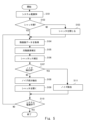
- FIG. 5 is a flow chart showing an image processing method.
- the user turns on the imaging system 1 (S101). For example, the user turns on the image processing device 100 and the infrared camera 200 .
- the shutter control unit 150 determines whether or not the shutter is closed (S102). If the shutter 220 is not closed (NO in S102), the shutter control unit 150 outputs a control signal for the shutter 220 to close the shutter 220 (S103).
- the thermal image data acquisition unit 160 acquires thermal image data in the closed state (S104).
- infrared camera 200 captures a uniform thermal image.
- the temperature sensor 250 detects the environmental temperature.
- a transmission device 240 transmits the thermal image data and the environmental temperature to the image processing apparatus 100 .
- the defective pixel correction unit 171 corrects the defective pixel (S105). For example, the pixel data (pixel value) of the defective pixel registered in advance is interpolated with the pixel data (pixel value) of the peripheral pixels. Thereby, the defective pixel correction unit 171 can correct the pixel data of the defective pixel.
- the correction unit 177 performs shutterless correction (S106). Thereby, shutterless corrected image data is generated.
- the noise component extraction unit 173 determines whether noise has been extracted (S107). For example, the noise component extractor 173 can extract the noise component when the system power is ON. In other words, the noise component extractor 173 extracts the noise component immediately after the system power is turned on.
- the noise component extraction unit 173 extracts the noise component from the shutterless corrected image data (S108). That is, the noise component extraction unit 173 calculates the noise component by subtracting the average value from the pixel data. As described above, the noise component extraction unit 173 extracts the noise component for each pixel, but may extract the noise component for each region including a plurality of pixels.
- the shutter control unit 150 opens the shutter 220 (S109). That is, the shutter control section 150 outputs a control signal to open the shutter 220 . It is determined whether or not the system power is off (S110). If the system power is not turned off (NO in S110), the process returns to step S104. That is, the thermal image data acquisition unit 160 acquires thermal image data in the shutter open state (S104). Also, the image processing apparatus 100 acquires the environmental temperature measured by the temperature sensor 250 .
- the defective pixel correction unit 171 corrects defective pixels (S105), and the correction unit 177 performs shutterless correction (S106). Thereby, a shutterless corrected image is generated.
- the noise component extraction unit 173 determines whether noise has been extracted (S107). Since the noise component extraction unit 173 has already extracted the noise component (YES in S107), the noise removal unit 178 removes noise from the shutterless corrected image (S111).
- the noise removal unit 178 removes noise components from the shutterless corrected image data.
- the noise removal unit 178 removes the noise component extracted in step S109 from the shutterless corrected image data to generate noise-removed image data.
- the system control unit 140 determines whether the system power is turned off (S110). If the system power is not turned off (NO in S110), the process returns to step S104 to repeat the process. That is, the image processing unit 170 performs shutterless correction and noise component removal for each acquired input thermal image data. The noise component n(w, h) in this repetition becomes common. If the system power is turned off (YES in S110), the process ends.
- the noise component changes over time.
- the image processing apparatus 100 extracts noise components when the imaging system 1 is powered on. This allows the image processing unit 170 to perform appropriate processing, thereby suppressing deterioration in image quality.
- a noise component that changes with time can be accurately extracted, and the measurement accuracy of the temperature distribution can be improved.
- the imaging system 1 can be an infrared camera imaging system mounted on an automobile or the like.
- the infrared camera 200 captures an image in front of the vehicle or around the vehicle.
- a display device 300 displays the output thermal image data. It can be an in-vehicle monitor.
- the system power supply of the imaging system 1 is turned on at the timing when the engine of the automobile is started. Therefore, the noise component extractor 173 can extract the noise component at each timing of starting the engine.
- the timing for extracting noise components is not limited to when the system power is on.
- the noise component extraction unit 173 may extract the noise component when a certain period of time or more has elapsed since the previous noise component extraction.
- the user may instruct extraction of noise components.
- the image processing device 100 and the infrared camera 200 are shown separately in FIG. 1, the image processing device 100 may be mounted on the infrared camera 200. Also, at least part of the processing of the image processing device 100 may be executed by the infrared camera 200 .
- the image processing apparatus 100 described above is not limited to a physically single apparatus. Therefore, a plurality of devices may distribute and execute the processing of the image processing device 100 .
- Embodiment 2 processing for detecting defective pixels and processing for correcting defective pixels are added to the processing of the first embodiment. It should be noted that other than these processes are the same as those of the first embodiment, and thus description thereof will be omitted as appropriate.
- FIG. 6 is a block diagram showing the image processing section 170 of the image processing apparatus 100 according to this embodiment.
- the configuration and processing other than the image processing unit 170 are the same as those of the first embodiment.
- the image processing unit 170 includes a defect data detection unit 174 and a defect data correction unit 175 in addition to the configuration of the first embodiment.
- the defective data detection unit 174 detects newly generated defective pixels.
- the defect data detection unit 174 obtains the pixel address of the defective pixel and updates the defective pixel information stored in the RAM 130 (see FIG. 1) or the like.
- the defect data detection unit 174 may calculate correction parameters according to the detected defects and record them in the RAM 130 or the like.
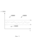
- FIG. 7 is a diagram showing shutterless corrected image data when the shutter is closed.
- FIG. 7 shows a profile showing the noise component n(w,h) as a function of pixel address.
- the horizontal axis indicates the pixel address w in the horizontal direction
- the vertical axis indicates the noise component.
- the defect data detection unit 174 detects defective pixels according to the result of comparison between a certain threshold value and the noise component n(w, h). For example, the defect data detector 174 stores a threshold Th+ and a threshold Th-.
- the threshold Th+ is a positive value and the threshold Th- is a negative value.
- the defective data detection unit 174 detects pixels whose noise component n(w, h) is equal to or greater than the threshold Th+ as defective pixels.
- the defect data detection unit 174 detects pixels whose noise component n(w, h) is equal to or less than the threshold value Th ⁇ as defective pixels.
- the defective data detection unit 174 updates the defective pixel address, which is the defective pixel information stored in the RAM 130 in advance, based on the pixel address of the detected defective pixel. By doing so, the pixel address of the newly detected defect and its information are stored in the RAM 130 .
- the defective pixel information is information indicating a defective pixel address and peripheral pixels used for interpolation processing.
- the defect data correction unit 175 removes data of defective pixels included in the extracted noise components, updates the noise components, and obtains noise components n′( w, h). That is, the noise component n'(w, h) indicates the noise component after defective pixel correction is performed on the noise component n(w, h).
- the NUC unit 172 performs shutterless correction and noise removal on the thermal image data in the open state (see FIG. 4). Shutterless correction by the correcting unit 177 is the same as in the first embodiment, so description thereof is omitted.
- the noise removal unit 178 removes noise using the noise component n'(w,h).
- the defect data correction unit 175 calculates the noise component n'(w, h) excluding the defective pixels detected by the defect data detection unit 174. Then, the noise removal unit 178 removes the noise component of the shutterless corrected image data based on n'(w, h) subjected to defective pixel correction. By doing so, more appropriate processing can be performed.
- FIG. 8 and 9 are flow charts showing the image processing method. Note that the processing from step S301 to step S308 is the same as that of the first embodiment, so description thereof will be omitted. The processing from steps S301 to S308 is the same as the processing from steps S101 to S108 in FIG.
- the user turns on the imaging system 1 (S301).
- the shutter control unit 150 determines whether the shutter is closed (S302). If the shutter 220 is not closed (NO in S302), the shutter control unit 150 closes the shutter 220 (S303). If the shutter 220 is closed (YES in S302), or if the shutter is closed in step S303, the thermal image data acquisition unit 160 acquires thermal image data in the closed state (S304).
- the defective pixel correction unit 171 corrects the defective pixel (S305).
- the correction unit 177 performs shutterless correction (S306). Thereby, shutterless corrected image data is generated.
- the noise component extraction unit 173 determines whether noise has been extracted (S307). If the noise has not been extracted (NO in S307), the noise component extraction unit 173 extracts the noise component from the shutterless corrected image data (S308). Thereby, the noise component n(w, h) is obtained.
- the defect data detection unit 174 determines whether the noise component is equal to or greater than the threshold (S309). If the noise component is greater than or equal to the threshold (YES in S309), the defect data detector 174 detects defect data (S310). For example, the defect data detection unit 174 compares the noise component with the thresholds Th+ and Th-, and detects defects based on the comparison result. Then, the defective data correction unit 175 removes defective pixels from the noise component n(w, h) (S311). Thereby, the noise component n'(w, h) to which the defective pixel correction has been applied is calculated. The defective data detection unit 174 updates the defective pixel information of the defective pixel correction unit 171 (S312). Thereby, the defective pixel information of the newly detected defective pixel is added to the defective pixel correction unit 171 . Then, the defective pixel correction unit 171 accumulates defect information.
- step S313 it is determined whether or not all pixels have been processed. If the processing of all pixels has not ended (NO in S313), the process returns to step S309. That is, the defect data detection unit 174 compares the noise component n(w, h) of the next pixel with the threshold to detect a new defect. If all pixels have been processed (YES in S313), the shutter control unit 150 opens the shutter 220 (S314).
- step S316 It is determined whether or not the system power is off (S316). If the system power is not off (NO in S316), the process returns to step S304. That is, the thermal image data acquisition unit 160 acquires thermal image data in the shutter open state (S304). Also, the image processing apparatus 100 acquires the environmental temperature measured by the temperature sensor 250 . Similarly to the above, the defective pixel correction unit 171 corrects defective pixels (S305), and the correction unit 177 performs shutterless correction (S306). Thereby, a shutterless corrected image is generated.
- the noise component extraction unit 173 determines whether noise has been extracted (S307). Since the noise component extraction unit 173 has already extracted the noise component (YES in S307), the noise removal unit 178 removes noise from the shutterless corrected image (S315). Here, the noise removal unit 178 removes the noise component n'(w, h) from the shutterless corrected image data. In addition to previously detected defective pixels, the defective pixels detected in step S310 are corrected.
- the system control unit 140 determines whether the system power is turned off (S316). If the system power is not turned off (NO in S316), the process returns to step S304. Here, since the noise has already been extracted, the processing is repeated in the order of steps S304, S305, S306, and S315. That is, the image processing unit 170 performs shutterless correction and noise component removal for each acquired input thermal image data. The noise component n'(w, h) in this repetition becomes common. If the system power is turned off (YES in S316), the process ends.
- the thermal image data can be processed more appropriately.
- the defective data detection unit 174 detects, as defective pixels, pixels in which the noise component n(w, h) is extremely large or extremely small compared to the noise component of normal pixels.
- the defect data detector 174 updates the information of the newly generated defective pixel.
- the defect data correction unit 175 updates the noise component by excluding data of defective pixels from the noise component n(w, h).
- the defective pixel correction unit 171 performs noise removal using the noise component '(w, h) from which the defective pixel data included in the newly generated noise component is removed. By doing so, a shutterless corrected image can be generated.
- the defect data detection unit 174 detects defects each time a noise component is extracted.
- the defective pixel correction unit 171 accumulates defect information indicating pixel addresses of defective pixels. By doing so, even if defects increase over time, the defective pixel correction unit 171 can appropriately reflect the defect information. Therefore, more appropriate processing can be performed, and measurement accuracy can be improved.
- Embodiment 3 This embodiment differs from the first and second embodiments in defect detection and defective pixel correction processing in the image processing unit 170 .
- An image processing apparatus according to this embodiment will be described with reference to FIG.
- FIG. 10 is a block diagram showing the configuration of the image processing section 170 of the image processing apparatus 100. As shown in FIG.
- the image processing unit 170 includes a defective pixel correction unit 171, an NUC unit 172, a filter processing unit 176, a difference calculation unit 179, and a defect data detection unit 174.
- the defective pixel correction unit 171 and the NUC unit 172 are the same as those in the first and second embodiments, so descriptions thereof are omitted.
- the filtering unit 176 performs filtering on the extracted noise component (w, h). Specifically, the filtering unit 176 applies a median filter to the noise component (w, h). Here, the filtering unit 176 uses a median filter with a pixel size of 3 ⁇ 3. Of course, the pixel size of the filter is not limited to 3 ⁇ 3. For example, the filter pixel size may be 5 ⁇ 5.
- the noise component (w, h) to which the median filter is applied is used as filtered image data.
- the difference calculation unit 179 calculates the difference between the noise component (w, h) and the filtered image data.
- the image data indicated by the difference value between the noise component (w, h) and the filtered image data is referred to as difference image data.
- Spike noise present in the noise component (w, h) is removed by applying a median filter.
- Spike noise is extracted from the differential image data.
- differential image data differential pixel data (luminance data) is close to 0 in areas other than spike noise.
- the defect data detection unit 174 detects defects by comparing the pixel data of the difference image data with the thresholds Th+ and Th ⁇ . By doing so, the defect detection accuracy can be improved.
- the noise components (w, h) are not necessarily uniform noise components in the vicinity of the quadrangle of the thermal image data and in the center.
- the imaging performance of the lens 210 may cause variations in pixel data, making it difficult to appropriately set the thresholds Th+ and Th- for defect detection.
- the difference calculator 179 calculates the difference between image data before and after filtering.
- the defect data detection unit 174 compares difference image data composed of difference values with a threshold value, and detects defects based on the comparison result. By doing so, the defect data detection unit 174 can set an appropriate threshold value, so that a defective pixel can be detected accurately.
- the threshold Th+ can be set to 1000, for example. If there is a pixel difference of 1000 or more between the center pixel and its eight neighboring pixels, it is detected as a defect.
- step S509 noise component filtering processing
- step S510 difference value calculation processing
- step S518 the processing of steps S310 to S316.
- the shutter control unit 150 determines whether the shutter is closed (S502). If the shutter 220 is not closed (NO in S502), the shutter control unit 150 closes the shutter 220 (S503). If the shutter 220 is closed (YES in S502), or if the shutter is closed in step S503, the thermal image data acquisition unit 160 acquires thermal image data in the closed state (S504).
- the defective pixel correction unit 171 corrects the defective pixel (S505).
- the correction unit 177 performs shutterless correction (S506). As a result, shutterless corrected image data is generated.
- the noise component extraction unit 173 determines whether noise has been extracted (S507). If the noise has not been extracted (NO in S507), the noise component extraction unit 173 extracts the noise component from the shutterless corrected image data (S508). As a result, the noise component n(w, h) before defective pixel correction is obtained.
- the filtering unit 176 filters the noise component (S509) That is, the filtering unit 176 applies the median filter to the noise component n(w, h). Filtered image data is thus obtained. Then, the difference calculator 179 calculates the difference value between the noise component and the filtered image data (S510).
- the defect data detection unit 174 determines whether the difference value is equal to or greater than the threshold (S511). If the difference value is greater than or equal to the threshold (YES in S511), the defect data detector 174 detects defect data (S512). For example, the defect data detection unit 174 compares the difference value with the thresholds Th+ and Th-, and detects defects based on the comparison result. Then, the defect data correction unit 175 removes defective pixels from the noise component n(w, h) (S513). Thereby, the noise component n'(w, h) to which the defective pixel correction has been applied is calculated. The defective data detection unit 174 updates the defective pixel information of the defective pixel correction unit 171 (S514). Thereby, the defective pixel information of the newly detected defective pixel is added to the defective pixel correction unit 171 . Then, the defective pixel correction unit 171 accumulates defect information.
- step S515 it is determined whether or not all pixels have been processed. If the processing of all pixels has not ended (NO in S515), the process returns to step S511. That is, the defect data detection unit 174 compares the difference value of the next pixel with the threshold to detect a new defect. If all pixels have been processed (YES in S515), the shutter control unit 150 opens the shutter 220 (S516).
- the process returns to step S504. That is, the thermal image data acquisition unit 160 acquires thermal image data in the shutter open state (S504). Also, the image processing apparatus 100 acquires the environmental temperature measured by the temperature sensor 250 . Similarly to the above, the defective pixel correction unit 171 corrects defective pixels (S505), and the correction unit 177 performs shutterless correction (S506). Thereby, a shutterless corrected image is generated.
- the noise component extraction unit 173 determines whether noise has been extracted (S507). Since the noise component extraction unit 173 has already extracted the noise component (YES in S507), the noise removal unit 178 removes noise from the shutterless corrected image (S517). Here, the noise removal unit 178 removes the noise component n'(w, h) from the shutterless corrected image data. In addition to previously detected defective pixels, the defective pixels detected in step S512 are corrected.
- the system control unit 140 determines whether the system power is turned off (S518). If the system power is not turned off (NO in S518), the process returns to step S504. Here, since the noise has already been extracted, the processing is repeated in the order of steps S504, S505, S506, and S517. That is, the image processing unit 170 performs shutterless correction and noise component removal for each acquired input thermal image data. The noise component n'(w, h) in this repetition becomes common. If the system power is turned off (YES in S518), the process ends.
- the processing in Embodiment 3 can be used in addition to the processing in Embodiment 1 or Embodiment 2.
- the defect information may be merged.
- the processing in the third embodiment can be performed independently of the processing in the first or second embodiment.
- the processing of Embodiment 3 may be performed on corrected image data after shutter correction.
- the image data to which the median filter is applied is not particularly limited.
- the data to which the median filter is applied is not limited to image data, and the median filter may be applied to a gain table or the like. That is, the median filter can be applied not only to the image data captured by the infrared camera 200 but also to the gain table, which is the correction value used when correcting the pixel variation. In this case, a pixel address with an extremely large gain or an extremely small pixel address is detected as a defect.
- Non-transitory computer-readable media include various types of tangible storage media. Examples of non-transitory computer-readable media include magnetic recording media (eg, flexible discs, magnetic tapes, hard disk drives), magneto-optical recording media (eg, magneto-optical discs), CD-ROMs (Read Only Memory), CD-Rs, Includes CD-R/W, semiconductor memory (eg, mask ROM, PROM (Programmable ROM), EPROM (Erasable PROM), flash ROM, RAM (Random Access Memory)).
- magnetic recording media eg, flexible discs, magnetic tapes, hard disk drives
- magneto-optical recording media eg, magneto-optical discs
- CD-ROMs Read Only Memory
- CD-Rs Includes CD-R/W
- semiconductor memory eg, mask ROM, PROM (Programmable ROM), EPROM (Erasable PROM), flash ROM, RAM (Random Access Memory)
- the program may also be delivered to the computer by various types of transitory computer readable media.
- Examples of transitory computer-readable media include electrical signals, optical signals, and electromagnetic waves.
- Transitory computer-readable media can deliver the program to the computer via wired channels, such as wires and optical fibers, or wireless channels.
- Imaging system 100 image processing device 110 control IF 120 ROMs 130 RAM 140 system control unit 150 shutter control unit 160 thermal image data acquisition unit 170 image processing unit 171 defect pixel correction unit 172 NUC unit 173 noise component extraction unit 174 defect data detection unit 175 defect data correction unit 176 filter processing unit 177 correction unit 178 noise Removal unit 179 Difference calculation unit 180 Display image data output unit 200 Infrared camera 210 Lens 220 Shutter 230 Sensor 240 Transmission device 250 Temperature sensor 300 Display device
Landscapes
- Physics & Mathematics (AREA)
- General Physics & Mathematics (AREA)
- Spectroscopy & Molecular Physics (AREA)
- Engineering & Computer Science (AREA)
- Multimedia (AREA)
- Signal Processing (AREA)
- Transforming Light Signals Into Electric Signals (AREA)
- Photometry And Measurement Of Optical Pulse Characteristics (AREA)
- Radiation Pyrometers (AREA)
- Studio Devices (AREA)
Abstract
本実施の形態にかかる画像処理装置は、赤外線カメラ(200)で撮像された熱画像データを取得する熱画像データ取得部(160)と、シャッタを閉じた状態の赤外線カメラ(200)で撮像された第1の熱画像データを、赤外線カメラ(200)の使用環境の環境温度及び予め取得された較正データに基づいて補正することで、シャッタレス補正画像データを生成する補正部(177)と、シャッタレス補正画像データに基づいて、経時的に変化するノイズ成分を抽出するノイズ成分抽出部(173)と、シャッタを開いた状態の赤外線カメラ(200)で撮像された第2の熱画像データのノイズ成分を除去するノイズ除去部(178)と、を備えている。
Description
本発明は、画像処理装置、画像処理方法、及びプログラムに関する。
特許文献1、2には赤外線画像撮像装置が開示されている。特許文献1の赤外線画像撮像装置は、温度センサで測定された環境温度に基づいて、予め複数設定された補正係数データにより補正データの更新作業を行わずに画素のばらつきを補正している。特許文献2の赤外線画像撮像装置は、シャッタを閉じた状態で画像を撮像している。赤外線画像撮像装置は、この画像から応答欠陥の画素を検出している。
赤外線撮像装置で用いられるマイクロボロメータ等の赤外線センサは、温度ストレス等による影響を受けて特性が経時的に変化していく。特許文献1の装置では、赤外線センサの温度ストレスなどによる経時的な特性の変化が生じた場合、赤外線センサの環境温度に対する出力特性の再現性が悪化し、適切に画素のばらつきを補正することが困難である。また、特許文献2の装置では、応答欠陥を検出しているため、欠陥を簡便に検出することが困難である。従って、適切な処理を行うことが困難となる。
本開示は上記の点に鑑みなされたものであり、赤外線センサでの経時的な特性の変化が起こった場合でも熱画像データを適切に処理することができる画像処理装置、画像処理方法,及びプログラムを提供する。
本実施形態にかかる画像処理装置は、赤外線カメラで撮像された熱画像データを取得する熱画像データ取得部と、シャッタを閉じた状態の前記赤外線カメラで撮像された第1の熱画像データを、前記赤外線カメラの使用環境の環境温度及び予め取得した較正データに基づいて補正することで、シャッタレス補正画像データを生成する補正部と、前記シャッタレス補正画像データに含まれる、経時的に変化するノイズ成分を抽出するノイズ成分抽出部と、前記シャッタを開いた状態の前記赤外線カメラで撮像された第2の熱画像データの前記ノイズ成分を除去するノイズ除去部と、を備えている。
本実施形態にかかる画像処理方法は、シャッタを閉じた状態の赤外線カメラで撮像された第1の熱画像データを取得するステップと、前記赤外線カメラの使用環境の環境温度及び予め取得した較正データに基づいて、前記第1の熱画像データを補正することで、シャッタレス補正画像データを生成するステップと、前記シャッタレス補正画像データに含まれる、経時的に変化するノイズ成分を抽出するステップ、前記シャッタを開いた状態の前記赤外線カメラで撮像された第2の熱画像データのノイズ成分を除去するステップと、を備えている。
本実施形態にかかるプログラムは、画像処理方法をコンピュータに実行させるプログラムであって、前記画像処理方法は、赤外線カメラのシャッタを閉じた状態で撮像された第1の熱画像データを取得するステップと、前記赤外線カメラの使用環境の環境温度及び予め取得した較正データに基づいて、前記第1の熱画像データを補正することで、シャッタレス補正画像データを生成するステップと、前記シャッタレス補正画像データに含まれる、経時的に変化するノイズ成分を抽出するステップと、前記シャッタを開いた状態の第2の熱画像データのノイズ成分を除去するステップと、を備えている。
本開示によれば、赤外線カメラでの熱画像データを適切に処理することができる画像処理装置、画像処理方法、及びプログラムを提供することを目的とする。
以下、本発明を適用した具体的な実施形態について、図面を参照しながら詳細に説明する。ただし、本開示が以下の実施形態に限定される訳ではない。また、説明を明確にするため、以下の記載及び図面は、適宜、簡略化されている。
実施の形態1.
本実施の形態にかかる画像処理装置、及び撮像システムについて、図1を用いて説明する。図1は、撮像システム1の構成を示すブロック図である。撮像システム1は、画像処理装置100と赤外線カメラ200と表示装置300とを備えている。撮像システム1は、例えば、車両において用いられ周囲の熱画像を取得する車両用の撮像システムや、監視用途に用いられる撮像システムなどである。
本実施の形態にかかる画像処理装置、及び撮像システムについて、図1を用いて説明する。図1は、撮像システム1の構成を示すブロック図である。撮像システム1は、画像処理装置100と赤外線カメラ200と表示装置300とを備えている。撮像システム1は、例えば、車両において用いられ周囲の熱画像を取得する車両用の撮像システムや、監視用途に用いられる撮像システムなどである。
赤外線カメラ200は、熱画像(赤外線画像)を撮像する。例えば、赤外線カメラ200は、被写体からの遠赤外線を検出することで、熱画像を撮像する。赤外線カメラ200は、物体から放射される遠赤外線を可視化することが可能な遠赤外線(FIR:Far Infrared Rays)カメラである。赤外線カメラ200で撮像した熱画像のデータを熱画像データ(又は赤外線画像データ)ともいう。熱画像データは、赤外線カメラ200の撮像範囲の温度分布を示す。
赤外線カメラ200は熱画像データを、画像処理装置100に出力する。なお、赤外線カメラ200から画像処理装置100に入力される熱画像データを入力熱画像データともいう。熱画像データは、赤外線カメラで撮像された熱画像データを示す。赤外線カメラ200の構成については後述する。
画像処理装置100は、入力熱画像データに対して画像処理を行うことで、表示画像データを生成する。例えば、画像処理装置100は、赤外線カメラ200の画素ばらつきの補正や、経時的な特性の変化によって生じるノイズ除去等の各種処理を行う。このようにすることで、温度をより正確に測定することができる。
画像処理装置100は、画像処理が施された表示画像データを表示装置300に出力する。なお、画像処理装置100で画像処理が施されて、表示装置300に出力される表示画像データを出力熱画像データともいう。つまり、入力熱画像データは画像処理装置100による処理前のデータであり、出力熱画像データは処理後のデータである。
表示装置300は、表示画像データを表示するための液晶ディスプレイ等を備えている。表示装置300は、画像処理装置100において、画像処理が施された表示画像データを表示する。これにより、表示装置300が、より正確な温度分布を表示することができる。
画像処理装置100は、制御IF(インタフェース)110,ROM(Read Only Memory)120、RAM(Random Access Memory)130、システム制御部140,シャッタ制御部150、熱画像データ取得部160,画像処理部170、表示画像データ出力部180を備えている。
熱画像データ取得部160は、赤外線カメラ200で撮像された熱画像データを取得する。例えば、赤外線カメラ200からの熱画像データを入力するためのIF(インターフェース)を備えている。なお、熱画像データ取得部160と、赤外線カメラ200とのインタフェースは、有線接続であってもよく、無線接続であってもよい。
ROM120は、画像処理装置100を制御するための制御プログラムや各種パラメータを格納する。例えば、ROM120は、画像処理部170で実行される画像処理プログラムを格納している。また、ROM120は、システム制御部140で実行されるシステム制御プログラムを格納している。
RAM130は、各種プログラムやその実行に用いるパラメータなどを格納している。さらに、画像処理部170の演算データ等を記憶する。
システム制御部140は、撮像システム1の全体を制御する.システム制御部140は、CPU(Central Processing Unit)等のプロセッサを備えている。システム制御部140のプロセッサが制御プログラムを実行することで、システム全体を制御することができる。
システム制御部140は、シャッタ制御部150を備えている。シャッタ制御部150は、赤外線カメラ200のシャッタの開閉を制御する。シャッタ制御部150は、シャッタを開閉するための制御信号を出力する。
制御IF110は、赤外線カメラ200を制御するためのインタフェースである。例えば、シャッタ制御部150は、制御IF110を介して、赤外線カメラ200を開閉するための制御信号を出力する。また、画像処理装置100は、制御IF110を介して、赤外線カメラ200に各種の信号やデータを送信することができる。さらに、制御IF110は、赤外線カメラ200からの各種の信号やデータを受信することができる。例えば、制御IF110は、赤外線カメラ200の温度センサで測定された環境温度を取得する。
画像処理部170は、熱画像データ取得部160で取得された熱画像データに対して、所定の画像処理を行う。画像処理部170は、画像処理プログラムを実行するためのプロセッサなどを備えていてもよい。画像処理部170のプロセッサは汎用プロセッサであってもよく、専用プロセッサであってもよい。画像処理部170のプロセッサとシステム制御部140のプロセッサは共通であってもよい。画像処理部170における処理については後述する。
画像処理部170が入力熱画像データに対して画像処理を行うことで、表示画像データが生成される。表示画像データ出力部180は表示画像データを表示装置300に出力するインタフェースである。
図2は赤外線カメラ200の詳細構成を模式的に示すブロック図である。赤外線カメラ200は、レンズ210、シャッタ220、センサ230,伝送デバイス240,及び温度センサ250を備えている。
レンズ210は、被写体からの遠赤外光をセンサ230の受光面に結像する。センサ230は、複数の画素を備えている。センサ230の各画素が被写体からの赤外光を受光する。これにより、被写体の熱画像を撮像することができる。例えば、センサ230は、遠赤外線を検出するためのマイクロボロメータを有している。センサ230は、2次元アレイ状配列された複数の画素を備えている。各画素の検出値(検出信号)が被写体の熱画像を形成する。
伝送デバイス240は、画像処理装置100に各種の信号やデータを伝送するためのインタフェースとなる。伝送デバイス240は、センサ230で撮像された熱画像データを画像処理装置100に伝送する。また、伝送デバイス240は、画像処理装置100からの制御信号を受信する。
温度センサ250は、赤外線カメラの使用環境における温度を測定する。伝送デバイス240は、温度センサ250で測定された環境温度を画像処理装置100に送信する。温度センサ250で測定された環境温度は後述するシャッタレス補正に用いられる。
シャッタ220は、センサ230の前面側に配置されている。シャッタ220は、外部からセンサ230に入射する赤外光を遮る。シャッタ220は、開閉可能な機構を有している。シャッタ220は、シャッタ制御部150からの制御信号によって開閉する。シャッタ220が閉じた状態(以下、単に閉状態ともいう)では、レンズ210からの外光がセンサ230に入射しなくなる。つまり、閉状態では、シャッタ220からの赤外光がセンサ230に入射する。シャッタ220が開いた状態(以下、単に開状態ともいう)では、レンズ210からの赤外光がセンサ230に入射する。なお、シャッタ220は、センサ230の撮像範囲を熱的な均一面とするとすることができる。例えば,シャッタ220は、レンズ210の前面側に配置されたバリヤ又はカバーのようなものであってもよい。
画像処理部170の構成について、図3を用いて説明する。図3は、画像処理部170の詳細構成を示すブロック図である。画像処理部170は、欠陥画素補正部171と、NUC(Non-Uniformity Correction)部172と、ノイズ成分抽出部173とを備えている。画像処理部170は、システム制御部140とRAM130と連携し、所定の処理を実行する。
欠陥画素補正部171は、RAM130に予め記憶されているセンサ230の欠陥画素の画素値を、欠陥画素の周辺の画素における画素値から補間処理を行う。欠陥画素補正部171は、熱画像データ取得部160が取得した入力熱画像データに対して、上述の補間処理を行い、補間処理を行った画像データを、NUC部172に出力する。
NUC(Non-Uniformity Correction)部172は、画素間の出力ばらつきを補正するための処理を行う。NUC部172の詳細構成を図4に示す。NUC部172は、補正部177とノイズ除去部178とを備えている。補正部177は、環境温度に基づいて入力熱画像データをシャッタレス補正する。
シャッタレス補正とは、例えば、シャッタ220を閉じずに、センサ230の画素ばらつきを、環境温度に対応した複数の補正値を用いて補正するものである。シャッタレス補正では、予め取得した較正データによる補正値を用いて、センサ230の出力の画素ばらつきが補正される。
センサ230は、環境温度に応じて温度ドリフト特性を持つため、環境温度によって画素ばらつきが変化する。したがって、赤外線カメラ200、又は画像処理装置100が予め複数の較正データを取得し、メモリなどに格納しておく。例えば、異なる7つの環境温度に対応した較正データが予め取得されている。予め取得されていない環境温度に対応した較正データは、予め取得されている複数の較正データを多項式などで近似した近似値を用いた補間処理で予測することができる。
センサ230のセンサ出力は、環境温度に応じて画素ばらつきが変化する。よって、センサ230が赤外光を受光した場合、そのときの環境温度に対する画素ばらつきを、予め取得した較正データを用いて補正する。補正部177は、予め取得した複数の較正データに基づいて、シャッタを用いた較正を行わずに、画素ばらつきの補正を行う。このような補正を、シャッタレス補正という。
補正部177によって、シャッタレス補正が施された熱画像データをシャッタレス補正画像データとする。つまり、シャッタレス補正画像データはシャッタレス補正処理が行われた熱画像データとなる。ノイズ除去部178は、経時変化によりセンサ特性が変化し、予め取得した較正データによる補正精度が悪化した場合にシャッタレス補正画像データに発生するノイズを除去する。ノイズ除去部178の処理については、後述する。
図3の説明に戻る。ノイズ成分抽出部173は、入力熱画像データにおけるノイズ成分を抽出する。具体的には、ノイズ成分抽出部173は、シャッタ220が閉じた状態のシャッタレス補正画像データからノイズ成分を抽出する。ノイズ成分は、センサ230の温度ストレスなどにより、経時的に変化する。ノイズ除去部178は、ノイズ成分抽出部173で抽出されたノイズ成分を除去するための処理を行っている。
補正部177による補正は、予め取得された較正データを用いて補正処理を行うことで、理想的には、どの環境温度においても画素ばらつきを補正することができる。しかしながら、センサ230は、経時的に特性が変化するため、予め取得した較正データによる補正精度が悪化した場合、シャッタレス補正画像にノイズが生じる。そこで、本実施の形態では、ノイズ成分抽出部173が、経時的に発生したノイズ成分を画素毎に抽出している。そして、ノイズ除去部178が、経時的に発生したノイズ成分を画素毎に除去している。
以下、シャッタレス補正後の画素データをIsless(w,h)とする。wは、水平方向の画素アドレスであり、hは垂直方向の画素アドレスである。経時的な変化により発生したノイズ成分をn(w,h)とする。n(w,h)はノイズ成分の2次元分布を示す。経時的に発生したノイズ成分を含むシャッタレス補正出力Iout(w,h)は以下の式(1)の通り、Isless(w,h)とn(w,h)の和で示される。
Iout(w,h)=Isless(w,h)+n(w,h) ・・・(1)
Iout(w,h)=Isless(w,h)+n(w,h) ・・・(1)
センサ230の特性は、経時変化するため、シャッタレス補正した画像データに発生するノイズ成分n(w,h)も徐々に増加していく。したがって、シャッタレス補正した画質も経時的に劣化してしまう。また、このノイズ成分n(w,h)には、新たに発生した欠陥画素情報も含まれる。
閉状態におけるシャッタレス補正後の画素データをIsless_T0(w,h)とする。T0は、閉状態において、温度センサ250で測定された環境温度である。つまり、T0はノイズ成分抽出処理時の環境温度である。
ノイズ成分抽出部173は、全画素のIsless_T0(w,h)の平均値を求めている。ノイズ成分抽出部173は、Isless_T0(w,h)から平均値を減算した減算値をノイズ成分として算出する。具体的には、ノイズ成分n(w,h)は以下の式(2)に示される。

なお、Wは水平方向の画素数であり、Hは垂直方向の画素数である。WとHの積が熱画像データの全画素数を示す。右辺第2項がIsless_T0(w,h)の画素平均値となる。つまり、Isless_T0(w,h)の総和を全画素数(W*sH)で除算した値が平均値となる。ノイズ成分抽出部173は、上記のような処理を行うことで、ノイズ成分n(w,h)を抽出する。
そして、ノイズ除去部178が開状態でのシャッタレス補正画像データに対して、ノイズ除去を行う。ノイズ除去部178はノイズ成分n(w,h)に基づいて、シャッタレス補正画像データのノイズを除去する。例えば、ノイズ除去部178は、以下の式(3)により、シャッタレス補正画像データの画素データのノイズを除去する。
Iout(w,h)=Isless_T(w,h)-α*n(w,h) ・・・(3)
Iout(w,h)=Isless_T(w,h)-α*n(w,h) ・・・(3)
ここで、Tは環境温度である。αは係数であり一定値となっている。もちろん、αは環境温度などに応じて変化する変数であってもよい。αは画素間で共通としているが、画素毎に異なっていてもよい。ここで、ノイズ除去部178でのノイズ除去処理が施されたシャッタレス補正画像データをノイズ除去画像データとする。つまり、ノイズ除去部178は、シャッタレス補正画像データに対してノイズ除去処理を行うことで、ノイズ除去画像データを生成する。
ノイズ除去部178は、ノイズ除去画像データを表示画像データ出力部180(図1参照)に出力する。表示画像データ出力部180はノイズ除去画像データを出力熱画像データとして、表示装置300に出力する。
このようにすることで、画像処理装置100は、入力熱画像データに生じた経時的に発生するノイズ成分を除去することができる。画像処理装置100は、閉状態での熱画像データによりノイズ成分を抽出しているため、より精度よくノイズ成分を抽出することができる。これにより、赤外線カメラ200の温度分布の測定精度を向上することができる。さらに、閉状態での熱画像データを撮像する毎に、ノイズ成分抽出部173がノイズ成分を抽出してもよい。これにより、ノイズ成分抽出部173が、ノイズ成分を繰り返し算出することができる。よって、画素毎に経時的な特性の変化度合いが異なる場合であっても適切に処理を行うことができる。
さらに、補正部177が、閉状態で撮像された熱画像データに対してシャッタレス補正を行っている。そして、ノイズ成分抽出部173が、閉状態のシャッタレス補正画像データに基づいて、ノイズ成分を抽出している。これにより、センサ230の経時変化によって、予め取得した較正データによる補正精度が悪化した場合に発生するノイズ成分を抽出することができる。
画像処理装置100は、抽出されたノイズ成分をメモリなどに記憶して、ノイズ成分を除去している。簡便な処理で経時劣化によるノイズ成分を除去することができるため、処理負荷を軽減することができる。また、ノイズ成分n(w,h)には、欠陥画素の情報も含まれる。上記のノイズ成分除去を行うことで、欠陥画素の画素データを適切に補正することができる。
以下、本実施の形態に係る画像処理方法について図5を用いて説明する。図5は、画像処理方法を示すフローチャートである。
まず、ユーザが撮像システム1の電源をONする(S101)。例えば、ユーザが画像処理装置100及び赤外線カメラ200の電源をオンにする。シャッタ制御部150は、シャッタが閉じているか否かを判定する(S102)。シャッタ220が閉じていない場合(S102のNO)、シャッタ制御部150がシャッタ220の制御信号を出して、シャッタ220を閉じる(S103)。
シャッタ220が閉じている場合(S102のYES)、又はステップS103でシャッタを閉じた場合、熱画像データ取得部160が閉状態での熱画像データを取得する(S104)。ここでは、赤外線カメラ200が均一な熱画像を撮像する。また、ここでは、温度センサ250が環境温度を検出する。伝送デバイス240が、熱画像データと環境温度とを画像処理装置100に送信する。
欠陥画素補正部171が欠陥画素を補正する(S105)。例えば、予め登録されている欠陥画素の画素データ(画素値)を周辺画素の画素データ(画素値)で補間する。これにより、欠陥画素補正部171が、欠陥画素の画素データを補正することができる。補正部177がシャッタレス補正を行う(S106)。これにより、シャッタレス補正画像データが生成される。ノイズ成分抽出部173は、ノイズが抽出済みか否かを判定する(S107)。例えば、システム電源ON時に、ノイズ成分抽出部173がノイズ成分を抽出することができる。つまり、システム電源がONとなった直後に、ノイズ成分抽出部173がノイズ成分を抽出する。
ノイズが抽出済みでない場合(S107のNO)、ノイズ成分抽出部173がシャッタレス補正画像データからノイズ成分を抽出する(S108)。つまり、ノイズ成分抽出部173は画素データから平均値を減算することで、ノイズ成分を算出する。上記の通り、ノイズ成分抽出部173は、画素毎にノイズ成分を抽出するが、複数の画素を含む領域毎にノイズ成分を抽出してもよい。
ノイズ成分の抽出が完了すると、シャッタ制御部150がシャッタ220を開く(S109)。つまり、シャッタ制御部150が制御信号を出力して、シャッタ220を開く。システム電源がOFFか否かを判定する(S110)。システム電源がOFF出ない場合(S110のNO)、ステップS104に戻る。つまり、熱画像データ取得部160がシャッタ開状態の熱画像データを取得する(S104)。また、画像処理装置100が、温度センサ250で測定された環境温度を取得する。
上記と同様に、欠陥画素補正部171が欠陥画素を補正し(S105)、補正部177がシャッタレス補正を行う(S106)。これにより、シャッタレス補正画像が生成される。ノイズ成分抽出部173が、ノイズを抽出済みか否かを判定する(S107)。ノイズ成分抽出部173が既にノイズ成分を抽出しているので(S107のYES)、ノイズ除去部178がシャッタレス補正画像のノイズを除去する(S111)。
ノイズ除去部178がシャッタレス補正画像データからノイズ成分を除去する。ノイズ除去部178が、ステップS109で抽出されたノイズ成分をシャッタレス補正画像データから除去して、ノイズ除去画像データを生成する。
システム制御部140が、システム電源がOFFされた否かを判定する(S110)。システム電源がOFFされていない場合(S110のNO)、ステップS104に戻り、処理を繰り返す。つまり、画像処理部170は、取得された入力熱画像データ毎にシャッタレス補正とノイズ成分除去を行う。この繰り返しでのノイズ成分n(w,h)は共通となる。システム電源がOFFされた場合(S110のYES)、処理を終了する。
ノイズ成分は経時的に変化する。例えば、撮像システム1の電源がオンしたときに画像処理装置100がノイズ成分を抽出するようにする。これにより、画像処理部170が適切に処理することができるため、画質の劣化を抑制することができる。経時的に変化するノイズ成分を正確に抽出することでき、温度分布の測定精度を向上することができる。
例えば、撮像システム1は自動車などに搭載された赤外線カメラ撮像システムとすることができる。赤外線カメラ200は、車両前方又は車両周辺を撮像する。表示装置300、出力熱画像データを表示する。車載モニタとすることができる。この場合、自動車のエンジンが起動するタイミングで,撮像システム1のシステム電源がオンする。よって、エンジン起動のタイミング毎にノイズ成分抽出部173がノイズ成分を抽出することができる。
システム電源をON直後に1度ノイズを抽出した後は、S107ではYESのフローでループする。よって、ノイズが抽出された後は、開状態での熱画像データが繰り返し取得される。もちろん、ノイズ成分を抽出するタイミングはシステム電源ON時に限られるものではない。例えば、前回のノイズ成分抽出から一定期間以上経過した場合に、ノイズ成分抽出部173がノイズ成分を抽出してもよい。あるいは、ユーザがノイズ成分の抽出を指示してもよい。
図1では、画像処理装置100と赤外線カメラ200が別体として示されているが、画像処理装置100は赤外線カメラ200に搭載されていてもよい。また、画像処理装置100の少なくとも一部の処理は、赤外線カメラ200で実行されていてもよい。上記の画像処理装置100は物理的に単一な装置に限られるものではない。よって、複数の装置が、画像処理装置100の処理を分散して実行していてもよい。
実施の形態2.
実施の形態2では、実施の形態1の処理に加えて欠陥画素を検出する処理と、欠陥画素を補正する処理が追加されている。なお、これらの処理以外は実施の形態1と同様であるため適宜説明を省略する。
実施の形態2では、実施の形態1の処理に加えて欠陥画素を検出する処理と、欠陥画素を補正する処理が追加されている。なお、これらの処理以外は実施の形態1と同様であるため適宜説明を省略する。
図6を用いて、本実施の形態にかかる画像処理について説明する。図6は、本実施の形態にかかる画像処理装置100の画像処理部170を示すブロック図である。なお、画像処理部170以外の構成及び処理は実施の形態1と同様である。画像処理部170は、実施の形態1の構成に加えて、欠陥データ検出部174と,欠陥データ補正部175を備えている。
欠陥データ検出部174は新たに発生した欠陥画素を検出する。欠陥データ検出部174は、欠陥となる画素の画素アドレスを求め、RAM130(図1参照)などに記憶されている欠陥画素の情報を更新する。または、欠陥データ検出部174は、検出した欠陥に応じた補正パラメータを算出して、RAM130などに記録してもよい。
欠陥データ検出部174による欠陥画素の検出について図7を用いて説明する。図7は、シャッタが閉状態におけるシャッタレス補正画像データを示す図である。図7は、画素アドレスに応じたノイズ成分n(w,h)を示すプロファイルを示している。図7では、横軸が水平方向の画素アドレスwを示し、縦軸がノイズ成分を示している。
ノイズ成分n(w,h)において、ノイズ成分が極端に大きくなる画素又は画素データが極端に小さくなるが画素が欠陥画素となりうる。したがって、欠陥データ検出部174は、ある閾値とノイズ成分n(w,h)との比較結果に応じて、欠陥画素を検出している。例えば、欠陥データ検出部174は閾値Th+と閾値Th-を格納している。閾値Th+は正の値で有り、閾値Th-は負の値となる。
欠陥データ検出部174は、ノイズ成分n(w,h)が閾値Th+以上となる画素を欠陥画素として検出する。欠陥データ検出部174は、ノイズ成分n(w,h)が閾値Th-以下となる画素を欠陥画素として検出する。欠陥データ検出部174は、検出した欠陥画素の画素アドレスに基づいて、RAM130に予め記憶された欠陥画素の情報である欠陥画素のアドレスを更新する。このようにすることで、新規に検出された欠陥の画素アドレスとその情報がRAM130に蓄積されている。欠陥画素の情報とは、欠陥の画素アドレスと、補間処理に用いる周辺画素を示す情報である。
欠陥データ補正部175は、抽出したノイズ成分に含まれる欠陥画素のデータを除去して、ノイズ成分を更新し、ノイズ成分n(w,h)から欠陥画素のデータを除去したノイズ成分n’(w,h)を生成する。つまり、ノイズ成分n’(w,h)は、ノイズ成分n(w,h)に対して欠陥画素補正が行われた後のノイズ成分を示す。
NUC部172は、開状態の熱画像データに対して、シャッタレス補正及びノイズ除去を行う(図4参照)。補正部177のシャッタレス補正は実施の形態1と同様であるため、説明を省略する。ノイズ除去部178は、ノイズ成分n’(w,h)を用いて、ノイズを除去する。ノイズ除去部178は、以下の式(4)に従ってノイズ除去する。
Iout(w,h)=Isless_T’(w,h)-α*n’(w,h)・・・(4)
Iout(w,h)=Isless_T’(w,h)-α*n’(w,h)・・・(4)
本実施の形態では、欠陥データ補正部175は、欠陥データ検出部174が検出した欠陥画素を除いたノイズ成分n’(w,h)を算出している。そして、ノイズ除去部178が、欠陥画素補正が行われたn’(w,h)に基づいて、シャッタレス補正画像データのノイズ成分を除去している。このようにすることで、より適切な処理を行うことができる。
次に、本実施の形態にかかる画像処理方法について、図8、図9を用いて説明する。図8,図9は画像処理方法を示すフローチャートである。なお、ステップS301~ステップS308までの処理は実施の形態1と同様であるため説明を省略する。ステップS301~ステップS308までの処理は図5のステップS101~S108までの処理と同様である。
まず、ユーザが撮像システム1の電源をONする(S301)。シャッタ制御部150は、シャッタが閉じているか否かを判定する(S302)。シャッタ220が閉じていない場合(S302のNO)、シャッタ制御部150が、シャッタ220を閉じる(S303)。シャッタ220が閉じている場合(S302のYES)、又はステップS303でシャッタを閉じた場合、熱画像データ取得部160が閉状態での熱画像データを取得する(S304)。
欠陥画素補正部171が欠陥画素を補正する(S305)。補正部177がシャッタレス補正を行う(S306)。これにより、シャッタレス補正画像データが生成される。ノイズ成分抽出部173は、ノイズが抽出済みか否かを判定する(S307)。ノイズが抽出済みでない場合(S307のNO)、ノイズ成分抽出部173がシャッタレス補正画像データからノイズ成分を抽出する(S308)。これにより、ノイズ成分n(w,h)が求められる。
欠陥データ検出部174が、ノイズ成分が閾値以上であるか否かを判定する(S309)。ノイズ成分が閾値以上の場合(S309のYES)、欠陥データ検出部174が欠陥データを検出する(S310)。例えば、欠陥データ検出部174は、ノイズ成分と閾値Th+、Th-を比較して、比較結果に基づいて、欠陥を検出する。そして、欠陥データ補正部175がノイズ成分n(w,h)から欠陥画素を除去する(S311)。これにより、欠陥画素補正が施されたノイズ成分n’(w,h)が算出される。欠陥データ検出部174は、欠陥画素補正部171の欠陥画素情報を更新する(S312)。これにより、新たに検出された欠陥画素の欠陥画素情報が、欠陥画素補正部171に追加される。そして、欠陥画素補正部171は欠陥情報を蓄積していく。
次に、全画素処理したか否かを判定する(S313)。全画素の処理が終了していない場合(S313のNO)、ステップS309に戻る。つまり、欠陥データ検出部174が
次の画素のノイズ成分n(w,h)と閾値を比較して、新たな欠陥を検出する。全画素処理した場合(S313のYES)、シャッタ制御部150が、シャッタ220を開く(S314)。
次の画素のノイズ成分n(w,h)と閾値を比較して、新たな欠陥を検出する。全画素処理した場合(S313のYES)、シャッタ制御部150が、シャッタ220を開く(S314)。
システム電源がOFFか否かを判定する(S316)。システム電源がOFFでない場合(S316のNO)、ステップS304に戻る。つまり、熱画像データ取得部160がシャッタ開状態の熱画像データを取得する(S304)。また、画像処理装置100が、温度センサ250で測定された環境温度を取得する。上記と同様に、欠陥画素補正部171が欠陥画素を補正し(S305)、補正部177がシャッタレス補正を行う(S306)。これにより、シャッタレス補正画像が生成される。
ノイズ成分抽出部173が、ノイズを抽出済みか否かを判定する(S307)。ノイズ成分抽出部173が既にノイズ成分を抽出しているので(S307のYES)、ノイズ除去部178がシャッタレス補正画像のノイズを除去する(S315)。ここでは、ノイズ除去部178がシャッタレス補正画像データからノイズ成分n’(w,h)を除去する。過去に検出された欠陥画素に加えて、ステップS310で検出された欠陥画素が補正される。
システム制御部140が、システム電源がOFFされた否かを判定する(S316)。システム電源がOFFされていない場合(S316のNO)、ステップS304に戻る。ここでは、ノイズ抽出済みであるため、ステップS304、S305,S306,S315の順で処理を繰り返す。つまり、画像処理部170は、取得された入力熱画像データ毎にシャッタレス補正とノイズ成分除去を行う。この繰り返しでのノイズ成分n’(w,h)は共通となる。システム電源がOFFされた場合(S316のYES)、処理を終了する。
このようにすることで、より適切に熱画像データを処理することができる。例えば、欠陥データ検出部174は、ノイズ成分n(w,h)が正常な画素のノイズ成分に比べて極端に大きくなる画素又は極端に小さくなる画素を欠陥画素として検出する。欠陥データ検出部174は、新たに発生した欠陥画素の情報を更新する。
欠陥データ補正部175は、ノイズ成分n(w,h)から欠陥画素のデータを除外して、ノイズ成分を更新する。欠陥画素補正部171は、新たに発生したノイズ成分に含まれる欠陥画素のデータが除外されたノイズ成分’(w,h)を用いてノイズ除去を行っている。このようにすることで、シャッタレス補正画像を生成することができる。
さらに、ノイズ成分の抽出毎に、欠陥データ検出部174が欠陥を検出する。そして、欠陥画素補正部171は欠陥画素の画素アドレスを示す欠陥情報を蓄積している。このようにすることで経時的に欠陥が増加していく場合であっても、欠陥画素補正部171が、欠陥情報を適切に反映させることができる。よって、より適切な処理を行うことができ、測定精度を向上することができる。
実施の形態3.
本実施の形態では、画像処理部170における欠陥の検出、及び欠陥画素補正の処理が実施の形態1,2と異なっている。本実施の形態の画像処理装置について、図10を用いて説明する。図10は、画像処理装置100の画像処理部170の構成を示すブロック図である。
本実施の形態では、画像処理部170における欠陥の検出、及び欠陥画素補正の処理が実施の形態1,2と異なっている。本実施の形態の画像処理装置について、図10を用いて説明する。図10は、画像処理装置100の画像処理部170の構成を示すブロック図である。
画像処理部170は、欠陥画素補正部171,NUC部172,フィルタ処理部176,差分算出部179,及び欠陥データ検出部174を備えている。欠陥画素補正部171とNUC部172は、実施の形態1、2と同様であるため説明を省略する。
フィルタ処理部176は、抽出されたノイズ成分(w,h)に対して、フィルタ処理を行う。具体的には、フィルタ処理部176は、ノイズ成分(w,h)に対して、メディアンフィルタを適用する。ここでは、フィルタ処理部176は、ピクセルサイズが3×3のメディアンフィルタを用いている。もちろん、フィルタのピクセルサイズは3×3に限定されるものではない。例えば、フィルタのピクセルサイズは、5×5であってもよい。
メディアンフィルタは、3×3=9画素の中央値を出力する。つまり、3×3の中心画素の画素データが中央値に置き換えられる。このようにすることでスパイクノイズを除去することができる。メディアンフィルタが適用されたノイズ成分(w,h)をフィルタ処理画像データとする。
差分算出部179は、ノイズ成分(w,h)とフィルタ処理画像データの差分を算出する。ノイズ成分(w,h)とフィルタ処理画像データの差分値が示す画像データを差分画像データとする。ノイズ成分(w,h)に存在するスパイクノイズが、メディアンフィルタを適用することで、除去されている。
差分画像データでは、スパイクノイズが抽出される。例えば、差分画像データでは、スパイクノイズ以外の部分では、差分画素データ(輝度データ)が0に近くなる。欠陥データ検出部174は、差分画像データの画素データを閾値Th+、Th-と比較することで、欠陥を検出する。このようにすることで、欠陥の検出精度を向上することができる。
例えば、ノイズ成分(w,h)は、熱画像データの四角近傍と、中央部で、均一なノイズ成分になるとは限らない。あるいは、レンズ210の結像性能の影響により、画素データにばらつきが生じるこのため、欠陥検出のための閾値Th+、Th-を適切に設定することが困難になる。
例えば、欠陥の検出感度を高くするため、閾値Th+を厳しく設定すると、熱画像データの四角近傍で欠陥を誤検出してしまう可能性が高くなる。よって、本実施の形態では、差分算出部179がフィルタ処理の前後の画像データの差分を算出している。欠陥データ検出部174は差分値から構成される差分画像データを閾値と比較して、比較結果に基づいて欠陥を検出している。このようにすることで、欠陥データ検出部174が、適切な閾値を設定することができるため、欠陥画素を正確に検出することができる。
画素データを14ビット(0~16383)とする。閾値Th+は例えば1000とすることができる。中心画素とその8近傍画素の中央値の画素差分が1000以上有れば、欠陥として検出される。
図11、図12は、本実施の形態にかかる画像処理方法を示すフローチャートである。本実施の形態では、実施の形態2のフローにおいて、ノイズ成分を抽出する処理(S508)の後に、ノイズ成分のフィルタ処理(ステップS509)と、差分値算出処理(S510)とが追加されている。そして、ステップS511において、差分値と閾値が比較されている。これらの以外のステップについては、実施の形態2と同様であるため、適宜説明を省略する。つまり、ステップS501~S508の処理は、ステップS301~S308の処理と同様の処理になっている。また、ステップS512~S518の処理は、ステップS310~S316の処理と同様になっている。
まず、ユーザが撮像システム1の電源をONする(S501)。シャッタ制御部150は、シャッタが閉じているか否かを判定する(S502)。シャッタ220が閉じていない場合(S502のNO)、シャッタ制御部150が、シャッタ220を閉じる(S503)。シャッタ220が閉じている場合(S502のYES)、又はステップS503でシャッタを閉じた場合、熱画像データ取得部160が閉状態での熱画像データを取得する(S504)。
欠陥画素補正部171が欠陥画素を補正する(S505)。補正部177がシャッタレス補正を行う(S506)。これにより、シャッタレス補正画像データが生成される。ノイズ成分抽出部173は、ノイズが抽出済みか否かを判定する(S507)。ノイズが抽出済みでない場合(S507のNO)、ノイズ成分抽出部173がシャッタレス補正画像データからノイズ成分を抽出する(S508)。これにより、欠陥画素補正が行われる前のノイズ成分n(w,h)が求められる。
欠陥画素補正部171が欠陥画素を補正する(S505)。補正部177がシャッタレス補正を行う(S506)。これにより、シャッタレス補正画像データが生成される。ノイズ成分抽出部173は、ノイズが抽出済みか否かを判定する(S507)。ノイズが抽出済みでない場合(S507のNO)、ノイズ成分抽出部173がシャッタレス補正画像データからノイズ成分を抽出する(S508)。これにより、欠陥画素補正が行われる前のノイズ成分n(w,h)が求められる。
フィルタ処理部176がノイズ成分をフィルタ処理する(S509)つまり、フィルタ処理部176がノイズ成分n(w,h)にメディアンフィルタを適用する。これにより、フィルタ処理画像データが求められる。そして、差分算出部179がノイズ成分とフィルタ処理画像データの差分値を算出する(S510)。
欠陥データ検出部174が、差分値が閾値以上であるか否かを判定する(S511)。差分値が閾値以上の場合(S511のYES)、欠陥データ検出部174が欠陥データを検出する(S512)。例えば、欠陥データ検出部174は、差分値と閾値Th+、Th-を比較して、比較結果に基づいて、欠陥を検出する。そして、欠陥データ補正部175がノイズ成分n(w,h)から欠陥画素を除去する(S513)。これにより、欠陥画素補正が施されたノイズ成分n’(w,h)が算出される。欠陥データ検出部174は、欠陥画素補正部171の欠陥画素情報を更新する(S514)。これにより、新たに検出された欠陥画素の欠陥画素情報が、欠陥画素補正部171に追加される。そして、欠陥画素補正部171は欠陥情報を蓄積していく。
次に、全画素処理したか否かを判定する(S515)。全画素の処理が終了していない場合(S515のNO)、ステップS511に戻る。つまり、欠陥データ検出部174が次の画素の差分値と閾値を比較して、新たな欠陥を検出する。全画素処理した場合(S515のYES)、シャッタ制御部150が、シャッタ220を開く(S516)。
システム電源がOFFか否かを判定する(S518)。システム電源がOFFでない場合(S518のNO)、ステップS504に戻る。つまり、熱画像データ取得部160がシャッタ開状態の熱画像データを取得する(S504)。また、画像処理装置100が、温度センサ250で測定された環境温度を取得する。上記と同様に、欠陥画素補正部171が欠陥画素を補正し(S505)、補正部177がシャッタレス補正を行う(S506)。これにより、シャッタレス補正画像が生成される。
ノイズ成分抽出部173が、ノイズを抽出済みか否かを判定する(S507)。ノイズ成分抽出部173が既にノイズ成分を抽出しているので(S507のYES)、ノイズ除去部178がシャッタレス補正画像のノイズを除去する(S517)。ここでは、ノイズ除去部178がシャッタレス補正画像データからノイズ成分n’(w,h)を除去する。過去に検出された欠陥画素に加えて、ステップS512で検出された欠陥画素が補正される。
システム制御部140が、システム電源がOFFされた否かを判定する(S518)。システム電源がOFFされていない場合(S518のNO)、ステップS504に戻る。ここでは、ノイズ抽出済みであるため、ステップS504、S505,S506,S517の順で処理を繰り返す。つまり、画像処理部170は、取得された入力熱画像データ毎にシャッタレス補正とノイズ成分除去を行う。この繰り返しでのノイズ成分n’(w,h)は共通となる。システム電源がOFFされた場合(S518のYES)、処理を終了する。
なお、実施の形態3における処理は、実施の形態1,又は実施の形態2の処理に追加して用いることができる。例えば、実施の形態2の欠陥検出と実施の形態3の欠陥検出を両方行った上で、欠陥の情報をマージしてもよい。また、実施の形態3における処理は、実施の形態1,又は2の処理と独立して実施することも可能である。例えば、シャッタ補正後の補正画像データに対して実施の形態3の処理を行ってもよい。さらに、メディアンフィルタが適用される画像データは特に限定されるものではない。
また、メディアンフィルタが適用されるデータは画像データに限定されるものではなく、ゲインテーブルなどにメディアンフィルタを適用してもよい。つまり、赤外線カメラ200で撮像された画像データに限らず、画素ばらつきを補正する際に使用する補正値であるゲインテーブルにメディアンフィルタを適用することができる。この場合、ゲインが極端に大きくなっている画素アドレスや、極端に小さくなっている画素アドレスは欠陥として検出される。
また、上述した画像処理装置100における処理の一部又は全部は、コンピュータプログラムとして実現可能である。このようなプログラムは、様々なタイプの非一時的なコンピュータ可読媒体を用いて格納され、コンピュータに供給することができる。非一時的なコンピュータ可読媒体は、様々なタイプの実体のある記録媒体を含む。非一時的なコンピュータ可読媒体の例は、磁気記録媒体(例えばフレキシブルディスク、磁気テープ、ハードディスクドライブ)、光磁気記録媒体(例えば光磁気ディスク)、CD-ROM(Read Only Memory)、CD-R、CD-R/W、半導体メモリ(例えば、マスクROM、PROM(Programmable ROM)、EPROM(Erasable PROM)、フラッシュROM、RAM(Random Access Memory))を含む。また、プログラムは、様々なタイプの一時的なコンピュータ可読媒体によってコンピュータに供給されてもよい。一時的なコンピュータ可読媒体の例は、電気信号、光信号、及び電磁波を含む。一時的なコンピュータ可読媒体は、電線及び光ファイバ等の有線通信路、又は無線通信路を介して、プログラムをコンピュータに供給できる。
以上、本発明者によってなされた発明を実施の形態に基づき具体的に説明したが、本発明は上記実施の形態に限られたものではなく、その要旨を逸脱しない範囲で種々変更可能であることは言うまでもない。上記の実施の形態の2つ以上を適宜組み合わせることも可能である。
この出願は、2021年12月20日に出願された日本出願特願2021-206168を基礎とする優先権を主張し、その開示の全てをここに取り込む。
1 撮像システム
100 画像処理装置
110 制御IF
120 ROM
130 RAM
140 システム制御部
150 シャッタ制御部
160 熱画像データ取得部
170 画像処理部
171 欠陥画素補正部
172 NUC部
173 ノイズ成分抽出部
174 欠陥データ検出部
175 欠陥データ補正部
176 フィルタ処理部
177 補正部
178 ノイズ除去部
179 差分算出部
180 表示画像データ出力部
200 赤外線カメラ
210 レンズ
220 シャッタ
230 センサ
240 伝送デバイス
250 温度センサ
300 表示装置
100 画像処理装置
110 制御IF
120 ROM
130 RAM
140 システム制御部
150 シャッタ制御部
160 熱画像データ取得部
170 画像処理部
171 欠陥画素補正部
172 NUC部
173 ノイズ成分抽出部
174 欠陥データ検出部
175 欠陥データ補正部
176 フィルタ処理部
177 補正部
178 ノイズ除去部
179 差分算出部
180 表示画像データ出力部
200 赤外線カメラ
210 レンズ
220 シャッタ
230 センサ
240 伝送デバイス
250 温度センサ
300 表示装置
Claims (5)
- 赤外線カメラで撮像された熱画像データを取得する熱画像データ取得部と、
シャッタを閉じた状態の前記赤外線カメラで撮像された第1の熱画像データを、前記赤外線カメラの使用環境の環境温度及び予め取得した較正データに基づいて補正することで、シャッタレス補正画像データを生成する補正部と、
前記シャッタレス補正画像データに含まれる、経時的に変化するノイズ成分を抽出するノイズ成分抽出部と、
前記シャッタを開いた状態の前記赤外線カメラで撮像された第2の熱画像データの前記ノイズ成分を除去するノイズ除去部と、を備えた画像処理装置。 - 前記ノイズ成分を閾値と比較することで、前記ノイズ成分に含まれる赤外線カメラの欠陥データを検出する欠陥データ検出部と、
前記欠陥データを除外して、前記ノイズ成分を更新する欠陥データ補正部と、をさらに備えた請求項1に記載の画像処理装置。 - 前記ノイズ成分に対してメディアンフィルタを適用するフィルタ処理部と、
前記メディアンフィルタを適用する前後の画像データの差分を算出する差分算出部と、をさらに備え、
前記差分に基づいて,欠陥画素を検出する請求項1、又は2に記載の画像処理装置。 - シャッタを閉じた状態の赤外線カメラで撮像された第1の熱画像データを取得するステップと、
前記赤外線カメラの使用環境の環境温度及び予め取得した較正データに基づいて、前記第1の熱画像データを補正することで、シャッタレス補正画像データを生成するステップと、
前記シャッタレス補正画像データに含まれる、経時的に変化するノイズ成分を抽出するステップと、
前記シャッタを開いた状態の前記赤外線カメラで撮像された第2の熱画像データのノイズ成分を除去するステップと、を備えた画像処理方法。 - 画像処理方法をコンピュータに実行させるプログラムであって、
前記画像処理方法は、
赤外線カメラのシャッタを閉じた状態で撮像された第1の熱画像データを取得するステップと、
前記赤外線カメラの使用環境の環境温度及び予め取得した較正データに基づいて、前記第1の熱画像データを補正することで、シャッタレス補正画像データを生成するステップと、
前記シャッタレス補正画像データに含まれる、経時的に変化するノイズ成分を抽出するステップと、
前記シャッタを開いた状態の第2の熱画像データのノイズ成分を除去するステップと、を備えた、プログラム。
Applications Claiming Priority (2)
| Application Number | Priority Date | Filing Date | Title |
|---|---|---|---|
| JP2021-206168 | 2021-12-20 | ||
| JP2021206168A JP2023091428A (ja) | 2021-12-20 | 2021-12-20 | 画像処理装置、画像処理方法、及びプログラム |
Publications (1)
| Publication Number | Publication Date |
|---|---|
| WO2023119751A1 true WO2023119751A1 (ja) | 2023-06-29 |
Family
ID=86901874
Family Applications (1)
| Application Number | Title | Priority Date | Filing Date |
|---|---|---|---|
| PCT/JP2022/034500 Ceased WO2023119751A1 (ja) | 2021-12-20 | 2022-09-15 | 画像処理装置、画像処理方法、及びプログラム |
Country Status (2)
| Country | Link |
|---|---|
| JP (1) | JP2023091428A (ja) |
| WO (1) | WO2023119751A1 (ja) |
Cited By (1)
| Publication number | Priority date | Publication date | Assignee | Title |
|---|---|---|---|---|
| WO2025074066A1 (fr) * | 2023-10-06 | 2025-04-10 | Safran Electronics & Defense | Méthode de correction de défauts optiques résiduels |
Citations (4)
| Publication number | Priority date | Publication date | Assignee | Title |
|---|---|---|---|---|
| JP2001124629A (ja) * | 1999-10-26 | 2001-05-11 | Nippon Avionics Co Ltd | 赤外線サーモグラフィーにおける1点補正手段の自己診断装置 |
| JP2002310804A (ja) * | 2001-04-11 | 2002-10-23 | Nec Corp | 赤外線撮像装置及びドリフト補正方法 |
| JP2004241818A (ja) * | 2003-02-03 | 2004-08-26 | Nec Corp | 赤外線撮像装置の固定パターンノイズ補正方法および固定パターンノイズ補正装置 |
| US20160065848A1 (en) * | 2014-08-28 | 2016-03-03 | Seek Thermal, Inc. | Thermography for a thermal imaging camera |
-
2021
- 2021-12-20 JP JP2021206168A patent/JP2023091428A/ja active Pending
-
2022
- 2022-09-15 WO PCT/JP2022/034500 patent/WO2023119751A1/ja not_active Ceased
Patent Citations (4)
| Publication number | Priority date | Publication date | Assignee | Title |
|---|---|---|---|---|
| JP2001124629A (ja) * | 1999-10-26 | 2001-05-11 | Nippon Avionics Co Ltd | 赤外線サーモグラフィーにおける1点補正手段の自己診断装置 |
| JP2002310804A (ja) * | 2001-04-11 | 2002-10-23 | Nec Corp | 赤外線撮像装置及びドリフト補正方法 |
| JP2004241818A (ja) * | 2003-02-03 | 2004-08-26 | Nec Corp | 赤外線撮像装置の固定パターンノイズ補正方法および固定パターンノイズ補正装置 |
| US20160065848A1 (en) * | 2014-08-28 | 2016-03-03 | Seek Thermal, Inc. | Thermography for a thermal imaging camera |
Cited By (2)
| Publication number | Priority date | Publication date | Assignee | Title |
|---|---|---|---|---|
| WO2025074066A1 (fr) * | 2023-10-06 | 2025-04-10 | Safran Electronics & Defense | Méthode de correction de défauts optiques résiduels |
| FR3153957A1 (fr) * | 2023-10-06 | 2025-04-11 | Safran Electronics & Defense | Méthode de correction de défauts optiques résiduels |
Also Published As
| Publication number | Publication date |
|---|---|
| JP2023091428A (ja) | 2023-06-30 |
Similar Documents
| Publication | Publication Date | Title |
|---|---|---|
| EP3621850B1 (en) | Shutterless far infrared (fir) camera for automotive safety and driving systems | |
| CN108353135B (zh) | 红外线摄像装置及基于红外线摄像装置的信号校正方法 | |
| US8208026B2 (en) | Systems and methods for processing infrared images | |
| US10742913B2 (en) | Shutterless calibration | |
| US12101569B2 (en) | Techniques for correcting oversaturated pixels in shutterless FIR cameras | |
| US20160065848A1 (en) | Thermography for a thermal imaging camera | |
| RU2717346C2 (ru) | Коррекция плохих пикселей в устройстве захвата инфракрасных изображений | |
| JP7306408B2 (ja) | 温度推定装置、温度推定方法及び温度推定プログラム | |
| US8481918B2 (en) | System and method for improving the quality of thermal images | |
| WO2020241471A1 (ja) | キャリブレーション方法 | |
| US10511793B2 (en) | Techniques for correcting fixed pattern noise in shutterless FIR cameras | |
| US20170163884A1 (en) | Infrared imaging device, fixed pattern noise calculation method, and fixed pattern noise calculation program | |
| US10699386B2 (en) | Techniques for scene-based nonuniformity correction in shutterless FIR cameras | |
| JP2023091428A (ja) | 画像処理装置、画像処理方法、及びプログラム | |
| KR102602846B1 (ko) | 적외선 화상 포착 장치의 기생 화소들의 검출 | |
| JP2016076851A (ja) | 撮像装置、画像処理方法、及びプログラム | |
| JP6251817B2 (ja) | 赤外線撮像装置、画像処理方法、及び画像処理プログラム | |
| JP2014017724A (ja) | 撮像装置 | |
| JP2013115702A5 (ja) | 撮像装置、及び撮像装置の制御方法 | |
| JP2010011161A (ja) | 撮像装置および撮像素子測温方法 | |
| JP2007174113A (ja) | 障害物検出システム及び障害物検出方法 | |
| KR101918761B1 (ko) | 적외선 열상 검출기의 불량 화소 처리 방법 및 장치 | |
| JP2024079035A (ja) | 撮像システム、ぶれ検出方法、及びプログラム | |
| JP2025065909A (ja) | 画像処理装置、及び画像処理方法 | |
| US9641765B2 (en) | Image capture device, image correction method, and image correction program |
Legal Events
| Date | Code | Title | Description |
|---|---|---|---|
| 121 | Ep: the epo has been informed by wipo that ep was designated in this application |
Ref document number: 22910477 Country of ref document: EP Kind code of ref document: A1 |
|
| NENP | Non-entry into the national phase |
Ref country code: DE |
|
| 122 | Ep: pct application non-entry in european phase |
Ref document number: 22910477 Country of ref document: EP Kind code of ref document: A1 |