WO2023119618A1 - O-ru及び管理方法 - Google Patents
O-ru及び管理方法 Download PDFInfo
- Publication number
- WO2023119618A1 WO2023119618A1 PCT/JP2021/048173 JP2021048173W WO2023119618A1 WO 2023119618 A1 WO2023119618 A1 WO 2023119618A1 JP 2021048173 W JP2021048173 W JP 2021048173W WO 2023119618 A1 WO2023119618 A1 WO 2023119618A1
- Authority
- WO
- WIPO (PCT)
- Prior art keywords
- signal processing
- digital signal
- vru
- unit
- state
- Prior art date
- Legal status (The legal status is an assumption and is not a legal conclusion. Google has not performed a legal analysis and makes no representation as to the accuracy of the status listed.)
- Ceased
Links
Images






Classifications
-
- H—ELECTRICITY
- H04—ELECTRIC COMMUNICATION TECHNIQUE
- H04L—TRANSMISSION OF DIGITAL INFORMATION, e.g. TELEGRAPHIC COMMUNICATION
- H04L25/00—Baseband systems
- H04L25/02—Details ; arrangements for supplying electrical power along data transmission lines
- H04L25/03—Shaping networks in transmitter or receiver, e.g. adaptive shaping networks
- H04L25/03828—Arrangements for spectral shaping; Arrangements for providing signals with specified spectral properties
- H04L25/03834—Arrangements for spectral shaping; Arrangements for providing signals with specified spectral properties using pulse shaping
- H04L25/03847—Shaping by selective switching of amplifying elements
-
- H—ELECTRICITY
- H04—ELECTRIC COMMUNICATION TECHNIQUE
- H04W—WIRELESS COMMUNICATION NETWORKS
- H04W24/00—Supervisory, monitoring or testing arrangements
- H04W24/04—Arrangements for maintaining operational condition
-
- H—ELECTRICITY
- H04—ELECTRIC COMMUNICATION TECHNIQUE
- H04W—WIRELESS COMMUNICATION NETWORKS
- H04W88/00—Devices specially adapted for wireless communication networks, e.g. terminals, base stations or access point devices
- H04W88/08—Access point devices
- H04W88/085—Access point devices with remote components
-
- H—ELECTRICITY
- H04—ELECTRIC COMMUNICATION TECHNIQUE
- H04W—WIRELESS COMMUNICATION NETWORKS
- H04W92/00—Interfaces specially adapted for wireless communication networks
- H04W92/04—Interfaces between hierarchically different network devices
- H04W92/12—Interfaces between hierarchically different network devices between access points and access point controllers
-
- H—ELECTRICITY
- H04—ELECTRIC COMMUNICATION TECHNIQUE
- H04W—WIRELESS COMMUNICATION NETWORKS
- H04W84/00—Network topologies
- H04W84/02—Hierarchically pre-organised networks, e.g. paging networks, cellular networks, WLAN [Wireless Local Area Network] or WLL [Wireless Local Loop]
- H04W84/04—Large scale networks; Deep hierarchical networks
- H04W84/042—Public Land Mobile systems, e.g. cellular systems
Definitions
- the present disclosure relates to an O-RU (Open Radio Access Network Radio Unit), an O-RU management method, and an O-RU management program.
- O-RU Open Radio Access Network Radio Unit
- O-RU management method Open Radio Access Network Radio Unit
- O-RU management program O-RU management program
- the fronthaul specifications of the O-RAN Alliance relate to links between RUs (Radio Units) and DUs (Distributed Units).
- Split Option 7-2x is adopted for baseband processing, and part of the physical layer processing (Low-PHY) is performed in the O-RU. Therefore, the O-RU includes a configuration for performing Low-PHY processing in addition to an RF (Radio Frequency) processing unit including an antenna.
- RF Radio Frequency
- Non-Patent Document 1 defines a management plane protocol used in fronthaul interfaces that link O-RUs and O-DUs. Although Non-Patent Document 1 describes O-RU software management, particularly activation, it does not specifically consider how to deal with an operation stop due to a restart or the like related to them.
- An object of the present disclosure is to provide an O-RU, an O-RU management method, and an O-RU management program for reducing the impact of stopping the operation of an O-RU or O-DU.
- an O-RU Open Radio Access Network Radio Unit
- the baseband section includes two or more digital signal processing sections.
- the two or more digital signal processing units are configured to execute digital signal processing with respective upper units
- the baseband unit is a part of the two or more digital signal processing units
- the O-RU is configured to perform the digital signal processing on the O-RU and to switch the digital signal processing unit that performs the digital signal processing.
- Each digital signal processing unit may maintain a state of being communicably connected to the upper unit determined for each.
- Each digital signal processing unit may be connected to the common RF unit.
- the digital signal processing unit that executes the digital signal processing may be switched, or the signals processed by the digital signal processing unit may be transmitted and received through the same antenna.
- a generating unit that generates the two or more digital signal processing units of the baseband unit may be further included.
- the upper unit may be an ODU (Open Radio Access Network Distributed Unit).
- ODU Open Radio Access Network Distributed Unit
- the digital signal processing section that executes the digital signal processing with the upper unit may be configured to be selected based on at least setting information.
- the digital signal processing unit that executes the digital signal processing with the upper unit may be switched by exclusive control between the digital signal processing units.
- the digital signal processing unit that executes the digital signal processing with the upper unit may be configured to switch when a switching command is received.
- Each digital signal processing unit operates according to a corresponding digital signal processing program, and the digital signal processing unit that executes the digital signal processing with the upper unit is switched based on at least the state of the digital signal processing program. It may be configured further.
- One aspect of the O-RU (Open Radio Access Network Radio Unit) management method is a plurality of digital signal processing units configured to execute digital signal processing with respective upper units. on the virtualization base of the O-RU, and each digital signal processing unit is placed in an operating state in which the digital signal processing can be performed, or in a dormant state in which the digital signal processing cannot be performed. a process of transitioning the state of each digital signal processing unit, and the start of wireless communication processing of the O-RU by a first digital signal processing unit in an operating state among the plurality of digital signal processing units.
- the management method includes starting wireless communication processing of the O-RU by the second digital signal processing unit in an operating state.
- FIG. 1 is a diagram illustrating an example of an O-RU and a radio access network to which the O-RU management method is applied according to an embodiment of the present disclosure.
- FIG. 2 is a diagram showing the O-RAN fronthaul.
- FIG. 3 is a schematic diagram showing the configuration of a general O-RU.
- FIG. 4 is a schematic diagram showing connections between O-DUs and O-RUs.
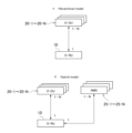
- FIG. 4A is a diagram showing a hierarchy model.
- FIG. 4B is a diagram showing a hybrid model.
- FIG. 5 is a schematic diagram showing an example of connection between an O-RU and a higher-level unit according to an embodiment of the present disclosure.
- FIG. 6 is a schematic diagram showing the configuration of an O-RU according to one embodiment of the present disclosure.
- FIG. 1 is a diagram illustrating an example of an O-RU and a radio access network to which the O-RU management method is applied according to an embodiment of the present disclosure.
- FIG. 2 is a diagram showing the O-
- FIG. 7 is a schematic diagram for explaining the operation of an O-RU according to an embodiment of the present disclosure.
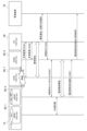
- FIG. 8 is a schematic diagram for explaining a first example of an O-RU operation and an O-RU management method according to an embodiment of the present disclosure.
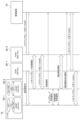
- FIG. 9 is a schematic diagram for explaining a second example of an O-RU operation and an O-RU management method according to an embodiment of the present disclosure.
- FIG. 10 is a schematic diagram for explaining a third example of an O-RU operation and an O-RU management method according to an embodiment of the present disclosure.
- FIG. 11 is a schematic diagram for explaining an example of O-RU operation according to an embodiment of the present disclosure.
- FIG. 12 is a flowchart illustrating an example of an O-RU management method according to an embodiment of the present disclosure.
- FIG. 1 is a diagram illustrating an example of an O-RU and a radio access network (RAN) to which the O-RU management method is applied according to an embodiment of the present disclosure.
- the radio access network 1 includes RUs (Radio Units) 10 , DUs (Distributed Units) 20 and CUs (Centralized Units) 30 .
- the radio access network 1 is a network that performs radio communication with radio terminals (UE), and as described later, the RU 10, DU 20, and CU 30 are functions for performing the radio communication, that is, so-called base stations. Allocate functions as a station.
- RU10 and DU20 may be O-RU10 and O-DU20, respectively.
- the radio access network 1 can also include, for example, an MEC (Mobile Edge Computing) server or a UPF (User Plane Function) as shown in FIG. .
- MEC Mobile Edge Computing
- UPF User Plane Function
- the radio access network 1 at least the RU 10, DU 20, and CU 30 are communicably connected wirelessly or by wire via a switch such as a router to form a virtual LAN (VLAN).
- VLAN virtual LAN
- a virtual LAN may in particular be a tagged VLAN (Tag VLAN).
- the connection between the RU 10 and the DU 20 in the radio access network 1 is called a fronthaul, and eCPRI (enhanced Common Public Radio Interface) is introduced as a fronthaul protocol.
- eCPRI enhanced Common Public Radio Interface
- FIG. 2 is a diagram showing the O-RAN fronthaul.
- RU (O-RU) 10 and DU (O-DU) 20 according to the O-RAN fronthaul specification will be described with reference to FIG.
- the O-RAN fronthaul specification adopts Split Option 7-2x in the 3.7 GHz and 4.5 GHz frequency bands (Sub 6 band).
- RF analog signal processing
- part of digital signal processing of the physical layer (Low-PHY) is done.
- the rest of the physical layer digital signal processing (High-PHY), the MAC layer, and the radio link layer are processed.
- FIG. 3 is a schematic diagram showing the configuration of a general O-RU.
- a typical O-RU 10 will be described in more detail with reference to FIG.
- the O-RU 10 includes a baseband section 110 for Low-PHY processing and an RF section 120 for analog signal processing.
- the RF unit 120 is communicatively connected to the antenna 130 and transmits/receives radio signals to/from a wireless terminal (UE).
- the O-RU 10 is communicably connected to the O-DU 20 .
- the baseband unit 110 performs processing generally referred to as Low-PHY processing, which is part of physical layer digital signal processing.
- Low-PHY processing includes, for example, precoding, beamforming, Fourier transform (FFT), and inverse Fourier transform (IFFT).
- FFT Fourier transform
- IFFT inverse Fourier transform
- the O-DU 20 can be configured with a VM (Virtual Machine) using virtualization technology. That is, the O-DU 20 can be configured as a VNF (Virtual Network Function) on NFVI (Network Functions Virtualization Infrastructure).
- the O-CU 30 can also be configured with a VM using virtualization technology.
- the O-RU 10 is communicably connected to one O-DU 20, but the number of O-DUs communicably connected to the O-RU 10 is not limited to one, as will be described later.
- one or more NMS Network Management System
- the O-DU and the NMS are collectively referred to as the "upper unit”.
- FIG. 4 is a schematic diagram showing connections between O-DUs and O-RUs.
- a connection form supported by the M-Plane (Management Plane) will be described with reference to FIG.
- FIG. 4A is a diagram showing a hierarchy model, in which N units (N is 1 or more) of O-DUs (O-DU 20-1 to O-DU 20-N) are communicably connected to the O-RU 10. indicates that That is, in the hierarchy model of FIG. 4A, N units of O-DUs (O-DU20-1 to O-DU20-N) correspond to upper units.
- N units of O-DUs O-DU20-1 to O-DU20-N
- 4B is a diagram showing a hybrid model, in which N (N is 1 or more) O-DUs (O-DU20-1 to O-DU20-N) and N NMSs (NMS25-1 to NMS25 -N) is communicatively connected to the O-RU 10. That is, in the hybrid model, O-DUs (O-DU20-1 to O-DU20-N) and NMSs (NMS25-1 to NMS25-N) correspond to upper units.
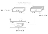
- FIG. 5 is a schematic diagram showing an example of connection between an O-RU and a higher-level unit according to an embodiment of the present disclosure.
- this connection format will be referred to as a new virtualization model.
- the baseband unit 110 in the O-RU 10 can be configured with a VM (Virtual Machine) using virtualization technology.
- This virtualized baseband unit is referred to herein as the "digital signal processing unit" or vRU.
- one O-RU 10 is configured with N (N is 1 or more) vRUs (vRU50-1 to vRU50-N) by virtualization.
- N is a number of 1 or more, and in particular, when N is 2 or more, one O-RU 10 can be configured with a plurality of vRUs (vRU50-1 to vRU50-N).
- These N vRUs (vRU50-1 to vRU50-N) are communicatively connected to corresponding N O-DUs (O-DU20-1 to O-DU20-N).
- N units (N is 1 or more) of vRUs may be communicably connected to corresponding N units of NMS (NMS25-1 to NMS25-N).
- the upper units are O-DUs (O-DU20-1 to O-DU20-N) or NMSs (NMS25-1 to NMS25-N).
- the N vRUs (vRU50-1 to vRU50-N) may be referred to as vRU#1 to vRU#N as aliases.
- N O-DUs (O-DU20-1 to O-DU20-N) may also be called O-DU#1 to O-DU#N.
- N units of O-DU 20, N units of NMS 25, and N units of vRU 50 are described, but the description does not mean that the number of O-DU 20, NMS 25, and vRU 50 is always the same.
- N is an arbitrary integer, and the value of N when representing the number of O-DU 20, the value of N when representing the number of NMS 25, and the value of N when representing the number of vRU 50 are different. good too. That is, the respective numbers of O-DUs 20, NMSs 25, and vRUs 50 may be different.
- FIG. 6 is a schematic diagram showing the configuration of the O-RU 10 according to one embodiment of the present disclosure.
- the O-RU 10 includes a baseband section 110 for digital signal processing and an RF section 120 for analog signal processing.
- RF section 120 is connected to antenna 130 .
- the number of RF units 120 and the number of antennas 130 are not limited to one, and any number of one or more may exist.
- the O-RU 10 complies with Split Option 7-2x, and that the digital signal processing in the baseband unit 110 performs Low-PHY processing.
- the O-RU 10 is not limited to Split Option 7-2x and may comply with the O-RAN fronthaul specifications, and the digital signal processing in the baseband unit 110 is not limited to Low-PHY processing.
- the baseband unit 110 can be configured by VM using virtualization technology.
- These N (N is 1 or more) virtualized baseband units are digital signal processing units (vRU50-1 to vRU50-N).
- the N digital signal processing units (vRU50-1 to vRU50-N) correspond to M units (M is 1 or more and N or less) upper units (O-DU20-1 to O-DU20-M, or , NMS 25-1 to NMS 25-M). That is, N (N is 1 or more) digital signal processing units (vRU50-1 to vRU50-N) may be connected to N different O-DUs 20-1 to 20-N, respectively.
- the number M of O-DUs connected to N may be smaller than N.
- NMS and N (N is 1 or more) digital signal processing units (vRU50-1 to vRU50-N) may be connected to N different NMS25-1 to NMS25-N, respectively.
- the NMSs communicably connected to each of the N may overlap and be the same. good. Therefore, the number M of NMSs connected to N (N is 2 or more) digital signal processing units (vRU50-1 to vRU50-N) may be smaller than N.
- each of N (N is 1 or more) digital signal processing units may be connected to the common RF unit 120.
- the baseband unit 110 is configured as a virtualization platform by an information processing device, and N units (N is 1 or more) of digital signal processing units (vRU50-1 to vRU50-N) are implemented by software on the information processing device. may be implemented.
- the baseband unit 110 includes a PLD (Programmable Logic Device) or an FPGA (Field Programmable Gate Array), and N (N is 1 or more) digital signal processing units (vRU50-1 to vRU50 -N) may be implemented in firmware on a PLD or FPGA.
- N N is 1 or more digital signal processing units (vRU50-1 to vRU50-N) can be generated by the virtualization control unit 140.
- the O-RU 10 may include components and the like not shown in FIG.
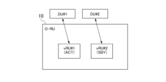
- FIG. 7 is a schematic diagram for explaining the operation of an O-RU according to an embodiment of the present disclosure.
- the O-RU 10 contains two virtualized digital signal processing units (vRU#1 and vRU#2). These two vRU#1 and vRU#2 are communicatively connected to corresponding upper units, DU#1 and DU#2, respectively.
- vRU#1 is in the active state (ACT) and vRU#2 is in the dormant state (SBY). That is, vRU#1 is communicably connected to DU#1 and performs digital signal processing such as Low-PHY processing. On the other hand, vRU#2 does not perform digital signal processing such as Low-PHY processing.
- the downstream signal from DU#1 is transmitted to vRU#1 in operation, and vRU#1 further performs digital signal processing such as Low-PHY processing on the signal, and RF unit 120 that performs analog signal processing. (FIG. 6), and further supplied from antenna 130 (FIG. 6) to a wireless terminal (UE) or the like. Further, the uplink signal supplied from the wireless terminal to the antenna 130 via radio waves is subjected to analog signal processing in the RF unit 120, and then subjected to digital signal processing such as Low-PHY processing in vRU#1 in the operating state. be. Then, the signal that has undergone digital signal processing in vRU#1 is sent to DU#1 for further processing.
- vRU#2 in the dormant state is communicably connected to DU#2, but may not perform digital signal processing such as Low-PHY processing.
- the result of digital signal processing performed by vRU#2 can be supplied to DU#2 without taking a procedure to establish a connection between vRU#2 and DU#2.
- digital signal processing can be performed on the signal supplied from DU#2. Therefore, switching from a dormant state to an active state for digital signal processing can be made more quickly. Therefore, a hibernation state in which digital signal processing such as Low-PHY processing is not performed while being communicably connected to a higher DU can be defined as a hot standby (Hot-SBY).
- Hot-SBY hot standby
- vRU#2 in the dormant state may not be communicably connected to DU#2 and may not perform digital signal processing such as Low-PHY processing.
- SBY dormant state
- a rest state in which the DU is not communicably connected to the upper DU and digital signal processing such as Low-PHY processing is not performed can be defined as cold standby (Cold-SBY).
- the signal is supplied to the RF unit 120 that performs analog signal processing, and is not supplied from the antenna 130 to the wireless terminal (UE) or the like.
- UE wireless terminal
- the dormant state of vRU#2 is hot standby, and DU#2 is in a state of receiving an uplink signal from vRU#2, in fact vRU#2 in the dormant state does not receive DU#2. No upstream signal is transmitted to the When the dormant state of vRU#2 is cold standby, it is further necessary to activate the digital signal processing of vRU#2 and establish a connection between vRU#2 and DU#2.
- FIG. 7 shows that vRU#1 is in the active state (ACT) and vRU#2 is in the dormant state (SBY), but the active state and dormant state of each vRU can be switched. It is possible. For example, when vRU#1 is switched from the operating state to the dormant state and vRU#2 is switched from the dormant state to the operating state, the RF unit used by vRU#1 among the plurality of RF units 120 The same RF unit 120 as 120 can be used by vRU#2.
- vRU#2 can be connected to the same antenna as the antenna 130 connected to vRU#1. That is, even if the digital signal processing unit that executes digital signal processing is switched between vRU#1 and vRU#2, the signals processed by the digital signal processing unit of vRU#1 or vRU#2 are transmitted and received through the same antenna. can
- the active state and the dormant state can be switched by exclusive control between vRU#1 and vRU#2. That is, in the O-RU 10, when one of the two digital signal processing units (vRU#1 and vRU#2) switches from the sleep state to the operating state, the other digital signal processing unit The two digital signal processors are controlled to switch from the active state to the dormant state. That is, when the state of one digital signal processing unit is changed, the other digital signal processing unit is also controlled so that only one digital signal processing unit is in the operating state. For example, in FIG.
- vRU#1 and vRU#2 have one digital signal processing unit that is in the operating state. Therefore, vRU#1 switches from the active state to the dormant state.
- the operating state and the dormant state can be switched by a switching command supplied from the outside of the O-RU 10 to vRU#1 or vRU#2.
- a switching command can be supplied to vRU#1 or vRU#2 by a management device that manages the system.
- the management device supplies a switching command from the outside of the O-RU 10 to switch vRU#1 to the operating state, even if vRU#1 is in the dormant state, it switches to the operating state.
- the management device supplies a switching command to put the vRU#1 into the dormant state from the outside of the O-RU 10
- the vRU#1 is switched to the dormant state even if it is in the operating state.
- vRU#2 it is possible to switch vRU#2 between the active state and the dormant state by supplying a switching command for switching to the active state or a switching command for the dormant state from the outside of the O-RU 10. is.
- exclusive control and control by a switching instruction can be combined. For example, assume that exclusive control is set between vRU#1 and vRU#2 in FIG.
- vRU#1 receives the switching command from the management device. Switches from active to dormant without
- the active state and dormant state can be switched by mutual control between vRU#1 and vRU#2.
- whether vRU#1 or vRU#2 should be in the active state or the dormant state is determined by the mutual relationship without receiving a switching command from the outside and without exclusive control. can control switching between active and dormant states.
- vRU#1 and vRU#2 are provided with corresponding first and second digital signal processing programs, respectively, and are operated by the first and second digital signal processing programs, respectively. . In this situation, it is possible to switch between an active state and a dormant state based on the mutual relationship between the first digital signal processing program and the second digital signal processing program.
- the first digital signal processing program of vRU#1 is an old version (also referred to as Old Version) of a certain digital signal processing program
- the second digital signal processing program of vRU#2 is the same digital signal processing program. It is assumed that there is a new version (also described as New Version). In that case, due to mutual control between vRU#1 and vRU#2, vRU#2 operating with the new version becomes active without receiving a switching command from the outside, and vRU#1 operating with the old version is activated. can go dormant.
- the baseband unit 110 of the O-RU 10 includes two vRUs that are communicatively connected to their corresponding DUs.
- the baseband unit of the O-RU 10 includes N (N is 2 or more) digital signal processing units (vRU), each of which is communicably connected to the corresponding upper unit.
- N is 2 or more digital signal processing units
- vRU digital signal processing units
- the baseband unit digital signal processing can be performed on some of the N vRUs, and the vRU that performs digital signal processing can be switched, that is, which vRU to perform digital signal processing.
- three methods of (1) exclusive control, (2) control by a switching instruction, and (3) mutual control can be used.
- FIG. 8 is a schematic diagram for explaining a first example of an O-RU operation and an O-RU management method according to an embodiment of the present disclosure.
- a first example of an O-RU operation and an O-RU management method according to the embodiment will be described with reference to FIG.
- the O-RU 10 is activated and incorporates exclusive control and redundancy of the digital signal processing unit (vRU).
- vRU digital signal processing unit
- FIG. 8 shows a system including O-RU 10, DU#1 (DU20-1), DU#2 (DU20-2), and CU30.
- O-RU 10 also includes a baseband section with two virtualized digital signal processing sections, vRU#1 (vRU50-1) and vRU#2 (vRU50-2). It should be noted that the number of vRUs and DUs is set to 2 in FIG. 8 for convenience of explanation, and the numbers may be any number of 2 or more.
- FIG. 8 shows a management device 70 that manages the system.
- the management device 70 may be an OSS (Operation Support System), an EMS (Element Management System), an NMS (Network Management System), or the like.
- the position of the management device 70 is not particularly limited, and it may be configured with other elements.
- the management device 70 may have the configuration of the CU 30, or may be provided in an MEC (Multi-access Edge Computing) server provided in an edge data center or a regional data center.
- MEC Multi-access Edge Computing
- vRU#1 and vRU#2 of the baseband units are also activated.
- vRU#1 and vRU#2 confirm each other's normal startup ("normal startup confirmation" in FIG. 8).
- the activation confirmation of the O-RU 10 and the normal activation of vRU#1 and vRU#2 are transmitted to the management device 70 as a power activation notification (“power activation notification” in FIG. 8).
- Which of vRU#1 and vRU#2 should transmit the power activation notification can be determined based on the setting information.
- the configuration information may be written in a configuration file. In FIG. 8, it is assumed that the data is transmitted from vRU #1 to the management device 70 .
- vRU#1 transmits an IP notification describing the IP address of vRU#1 and a setting request notification for connecting to DU#1 set as a connection destination to the management device 70 ("vRU# 1 IP notification, setting request notification (DU#1)").
- Which DU (DU #1 in the example of FIG. 8) is the upper unit that is communicatively connected to vRU #1 may be determined in advance as configuration information, or may be described in a configuration file. good.
- vRU#2 sends an IP notification describing the IP address of vRU#2 and a setting request notification for connecting to DU#2 set as a connection destination to the management device 70 ("vRU #2 IP notification, setting request notification (DU#2)"). Communicative connection of vRU#2 to DU#2 may be based on configuration information.
- Exclusive control is set for vRU#1 and vRU#2 (“Exclusive control setting” in FIG. 8). That is, as described above, the two digital signal processing units of vRU#1 and vRU#2 in the O-RU 10 are controlled such that only one digital signal processing unit is in the operating state. At this point, which of vRU#1 and vRU#2 should be put into the operating state may be determined according to the order of activation or setting information described in a setting file. In FIG. 8, vRU#1 is set to active state (ACT), and vRU#2 is set to dormant state (SBY).
- ACT active state
- SBY dormant state
- a completion notice is sent to the management device 70 (“completion notice” in FIG. 8). Which of vRU#1 and vRU#2 should send the completion notification, like the power activation notification, can be determined based on the setting information. In FIG. 8, the completion notification is transmitted to the management device 70 from vRU#1.
- the management device 70 Upon receiving the completion notification, the management device 70 deploys DU#1 on NFVI based on the setting request notification from vRU#1. In particular, DU#1 and vRU#1 are communicably connected, and DU#1 is made to set connection with vRU#1 (“Deploy, Config setting (DU#1)” in FIG. 8). Also, the management device 70 deploys DU#2 on the NFVI based on the setting request notification from vRU#2. In particular, DU#2 and vRU#2 are communicably connected, and DU#2 is made to set connection with vRU#2 (“Deploy, Config setting (DU#2)” in FIG. 8).
- the management device 70 instructs the CU 30 to connect DU #1 and vRU #1 (this connection is also the connection between DU #1 and O-RU 10), and connect DU #2 and vRU #2 (this The connection is also the connection between DU#2 and O-RU 10), and causes the CU 30 to set the connection with DU#1 and DU#2 (“Config setting” in FIG. 8).
- the first communication processing configuration by CU30, DU#1, and O-RU10 in other words, the second communication processing configuration by the first base station, CU30, DU#2, and O-RU10, in other words, the second A radio access network including base stations is configured.
- vRU#2 is in a dormant state (SBY) in which digital signal processing is not performed, but is in a hot standby state in which the connection state with DU#2 is maintained.
- SBY dormant state
- ACT active state
- digital signal processing with DU#2 can be executed quickly. That is, in response to vRU#2 being in a hot standby state, the second base station by CU 30, DU#2 and O-RU 10 is considered to be in a dormant state (hot standby) while the power is on. can be done.
- an M-Plane including DU#1 and vRU#1 and an M-Plane including DU#2 and vRU#2 are established.
- vRU#1 and vRU#2 are under exclusive control, and vRU#1 is in an active state (ACT) for performing digital signal processing, while vRU#2 is connected to DU#2, but is not performing digital signal processing. It is in a hot standby state (Hot-SBY) that does not operate. Therefore, DU#1 and vRU#1 start radio signal transmission/reception (“M-Plane is established, radio wave emission starts” in FIG. 8), but radio wave transmission/reception is started for DU#2 and vRU#2. (“M-Plane Established, Radio Wave Emission Hold” in FIG. 8).
- vRU#1 and vRU#2 can mutually confirm establishment of M-Plane and radio wave emission start or radio wave emission hold (“normal confirmation” in FIG. 8).
- FIG. 9 is a schematic diagram for explaining a second example of an O-RU operation and an O-RU management method according to an embodiment of the present disclosure.
- a second example of the O-RU operation and O-RU management method according to the embodiment will be described with reference to FIG.
- redundancy of the digital signal processing units (vRU#1 and vRU#2) is incorporated as in the first example shown in FIG. 8, for example.
- the O-RU 10 may or may not incorporate exclusive control between vRU#1 and vRU#2.
- FIG. 9 for O-RU 10 consider as an example a situation where DU#1 connected to vRU#1 in active state (ACT) has failed. In this case, the M-Plane including vRU#1 is no longer established, and radio wave emission and radio wave incidence at the O-RU 10 are interrupted.
- ACT active state
- FIG. 9 shows a system including O-RU 10, DU#1 (DU20-1), DU#2 (DU20-2), and CU30.
- O-RU 10 also includes a baseband section with two virtualized digital signal processing sections, vRU#1 (vRU50-1) and vRU#2 (vRU50-2).
- the O-RU 10 incorporates redundancy in the digital signal processing unit by allowing only one vRU to perform digital signal processing and start radio wave emission.
- vRU#1 is in an active state (ACT)
- vRU#2 is in a dormant state (Hot-SBY) in which digital signal processing is not performed while being communicably connected to DU#2.
- ACT active state
- Hot-SBY dormant state
- the number of vRUs and DUs is set to 2 in FIG. 9 as well for convenience of explanation, and the numbers may be any number of 2 or more.
- DU#1 If DU#1 is normal, M-Plane is established between vRU#1 and DU#1 in operation, and radio waves are emitted or incident on O-RU 10 by the operation of vRU#1. However, if a failure occurs in DU#1, the M-Plane between vRU#1 and DU#1 will not be established, and radio wave emission and incidence by O-RU 10 via vRU#1 will stop.
- the CU 30 constantly monitors DU#1 and DU#2 ("regular monitoring (DU#1)" and "regular monitoring (DU#2)" in FIG. 9). Therefore, the CU 30 detects that a failure has occurred in DU#1 ("abnormality detection" in FIG. 9).
- DU#2 It also detects that DU#2 is normal.
- the detection by the CU 30 and the switching schedule of DU#1 and DU#2 are notified to the management device 70 (“abnormality notification, switching schedule notification” in FIG. 9).
- Monitoring by the CU 30 may use a general network monitoring method.
- the management device 70 issues an instruction to switch between DU#1 and DU#2 to DU#2 ("switching instruction (DU#2)" in FIG. 9).
- switching instruction (DU#2) in FIG. 9
- DU#2 receives a switching command from the management device 70, it issues a switching command to the O-RU 10 to switch the states of vRU#1 and vRU#2 (“Switching command (O-RU or vRU#2)”).
- the digital signal processing unit that executes digital signal processing with the connected DU is switched (“inter-RU switching” in FIG. 9).
- vRU#1 that was in the active state (ACT) becomes the dormant state (SBY). If the communicable connection between vRU#1 and DU#1 is maintained, hot standby occurs, but if the communicable connection between vRU#1 and DU#1 is lost due to a failure, cold standby occurs. Then, vRU#2, which has been in a dormant state (Hot-SBY) while being communicably connected to DU#2, enters an active state (ACT) and enters a state of performing digital signal processing.
- Hot-SBY dormant state
- vRU#2 when vRU#1 and vRU#2 are under exclusive control, the switching command from DU#2, instead of being sent to the O-RU 10, vRU#2 is communicatively connected to DU#2. (“Switching command (O-RU or vRU#2)” in FIG. 9). Since the state of vRU#2 changes when it receives a switching command, it changes from the dormant state (Hot-SBY) to the active state (ACT). Since vRU#1 and vRU#2 are exclusively controlled, vRU#1 changes from the operating state (ACT) to the dormant state (SBY) as vRU#2 changes to the operating state (see FIG. 9). “Inter-RU switching”).
- vRU#2 becomes an operating state, since the M-Plane has been established between DU#2 and vRU#2, the held radio wave emission is started (“Radio wave emission start” in FIG. 9).
- vRU # 2 confirms the start of radio wave emission, it transmits a radio wave emission success notification to DU # 2 (“Radio wave emission success notification (DU # 2 )” in FIG. 9), and DU # 2 also sends a message to CU 30 or management device 70 can transmit a radio wave emission success notification (“radio wave emission success notification (management device)” in FIG. 9).
- vRU#1 and DU#1 that have been emitting radio waves are controlled by a switching command to O-RU10 or a switching command to vRU#2 and exclusive control between vRU#1 and vRU#2. Even if a failure occurs in the O-RU side, the switching between vRU#1 and vRU#2 is quickly performed. Then, the second base station by O-RU 10, DU#2, and CU 30 becomes available, enabling quick restoration of the radio access network.
- the failed DU#1 Since the failed DU#1 is disconnected from the radio access network, it can be restored without stopping the operation of the radio access network. Also, if DU #1 is restored, by connecting with vRU #1 in the dormant state as necessary, the use of the first base station by O-RU 10, DU #1 and CU 30 becomes possible again. Become.
- FIG. 10 is a schematic diagram for explaining a third example of an O-RU operation and an O-RU management method according to an embodiment of the present disclosure.
- a third example of the O-RU operation and O-RU management method according to the embodiment will be described with reference to FIG.
- redundancy of the digital signal processing units vRU#1 and vRU#2
- the O-RU 10 may or may not incorporate exclusive control between vRU#1 and vRU#2.
- FIG. 10 shows a system including O-RU 10, DU#1 (DU20-1), and DU#2 (DU20-2). Although the description of the CU is omitted in FIG. 10, the CU is connected to DU#1 and DU#2.
- O-RU 10 also includes a baseband section with two virtualized digital signal processing sections, vRU#1 (vRU50-1) and vRU#2 (vRU50-2).
- vRU#1 is in an active state (ACT)
- vRU#2 is in a resting state (Hot-SBY) in which digital signal processing is not performed while being communicably connected to DU#2.
- ACT active state
- Hot-SBY resting state
- the software version of DU#1 is "Old Version”
- the software version of DU#2 is "Old Version”.
- the "Old Version” has been updated to the "New Version”.
- the first base station is transmitting and receiving radio waves ("Emitting radio waves" in FIG. 10).
- the software of DU#2 that is communicatively connected to vRU#2 in a dormant state is changed to "Old Version" without stopping the operation as a radio access network. " to "New Version” ("Complete software upgrade (DU#2)" in FIG. 10).
- the software upgrade in DU#2 may be controlled between the management device 70 and DU#2.
- Completion of the software upgrade process in vRU#2 is notified to DU#2 (“soft upgrade complete (vRU#2)” in FIG. 10).
- Completion of the software upgrade process means that vRU#2 has been rebooted due to the software upgrade process, and that a connection that allows communication between vRU#2 and DU#2 is maintained.
- the software-upgraded vRU#2 is communicably connected to the software-upgraded DU#2 and is in the hibernation state (Hot-SBY).
- vRU#2 which has completed the software upgrade process, notifies the management device 70 that it should switch between the active state and the dormant state with vRU#1 (“switching notification” in FIG. 10). Then, vRU#1 and vRU#2 exchange their software statuses, especially software update statuses (“upgrade status notification” in FIG. 10). As a result, vRU#1 and vRU#2 mutually recognize which software version is newer.
- vRU#1 and vRU#2 are mutually controlled according to the status of their respective digital signal processing programs, that is, based on which software version is newer, and vRU#1 and vRU#2 are mutually controlled for digital signal processing with DU.
- a dormant vRU can be switched.
- the interaction between vRU#1 and vRU#2 Under the control vRU#2 that operates with the new version is switched to the active state, and vRU#1 that operates with the old version is switched to the dormant state (“switching control/state notification” in FIG. 10).
- vRU#1 and vRU#2 notify each other of their states (operating state or dormant state) (“switching control/state notification” in FIG. 10).
- FIG. 11 is a schematic diagram for explaining an example of O-RU operation according to an embodiment of the present disclosure.
- the O-RUs before the upgrade are vRU#1 whose software is the old version and is in the active state (ACT), and vRU# whose software is the new version and is in the hibernation state (Hot SBY).
- the O-RU 10 before the upgrade includes vRU#1 whose software is the old version and is in the hibernation state (Hot SBY), and vRU#2 whose software is the new version and is in the active state (ACT).
- pre-upgrade O-RU 10 and post-upgrade O-RU 10 switch vRU#2 operating on the new version to operating state and switch vRU#1 operating on the old version to dormant state (" This is the state before and after "switching control/state notification").
- the O-RU 10 is upgraded by switching the vRU#2 operating in the new version from the hibernation state (Hot SBY) to the operation state (ACT).
- the process returns to the state where vRU#2 operating with the new version is set to the active state (ACT) and vRU#1 operating with the old version is set to the hibernation state (Hot SBY).
- M-Plane is established between vRU#1 and DU#1, but since vRU#1 is in a dormant state where digital signal processing is not performed, radio wave emission from DU#1 to vRU#1 is held. It is On the other hand, since the M-Plane is established between vRU#2 and DU#2, and vRU#2 is in an operating state where digital signal processing is performed, radio waves relating to vRU#2 are emitted from DU#2. And the injection starts (“Radio wave emission start” in FIG. 10). Then, when the success of radio wave emission is confirmed, vRU#2 supplies a radio wave emission success notification to the management device 70 (“radio wave emission success notification” in FIG. 10).
- the radio wave emission success notification When the radio wave emission success notification is sent, it means that the radio wave emission by DU#2 and vRU#2 whose software has been upgraded has been confirmed. Completion is recognized.
- the mutual control of vRU#1 and vRU#2 makes it possible to quickly update the software of DU and vRU without substantially stopping the operation of the radio access network.
- the suspension of operation of the radio access network due to the update is short (on the order of milliseconds) due to switching control between vRU#1 and vRU#2.
- the restart at the time of upgrade typically causes a power outage time of several tens of minutes, and in the case of software update, the power outage time is long. significantly shortened.
- FIG. 10 explained the vRU software update triggered by the software update in DU#2, but the software update on the DU side is not essential.
- the software update on the DU side is not essential.
- the software of vRU#2 is updated, and mutual control can activate vRU#2 running on the new version and deactivate vRU#1 running on the old version.
- FIG. 12 is a flowchart illustrating an example method 1000 for managing an O-RU (Open Radio Access Network Radio Unit) according to an embodiment of the present disclosure.
- O-RU Open Radio Access Network Radio Unit
- the O-RU follows the O-RAN fronthaul specification, eg, as shown in FIGS.
- the O-RU includes, for example, an RF (Radio Frequency) section for analog signal processing and a baseband section for digital signal processing, as shown in FIG.
- RF Radio Frequency
- baseband section for digital signal processing
- FIG. 4 is analog signal processing (RF) such as D / A conversion or A / D conversion and analog beam forming
- RF analog signal processing
- Low-PHY digital signal processing
- the managed O-RU includes multiple digital signal processing units (in FIG. 12, they are also described as the first vRU, the second vRU, etc.) in the baseband unit.
- a plurality of digital signal processing units (vRUs) are configured to perform digital signal processing with respective upper units.
- the upper unit may be a DU, in particular a virtualized DU.
- the baseband section is configured to allow part of the plurality of digital signal processing sections to perform digital signal processing.
- a digital signal processing unit that can perform digital signal processing is said to be in an operating state (described as “active” in FIG. 12), and a digital signal processing unit that cannot perform digital signal processing is said to be in a resting state (in FIG. 12, “ It is said that it is in "Standby”).
- the management method 1000 includes a process (1100 in FIG. 12) of creating a plurality of digital signal processing units on the virtualization infrastructure in the O-RU.
- the process of generating a plurality of digital signal processing units may be performed when the O-RU is activated by powering on the O-RU, receiving an activation signal, or the like.
- the management method 1000 includes state transition processing (1200 in FIG. 12) of each digital signal processing unit.
- each digital signal processing unit is either in an operating state in which digital signal processing is performed, or in a dormant state in which digital signal processing is not performed.
- state transition processing (1200 in FIG. 12) of each digital signal processing unit is performed, only one digital signal processing unit among the plurality of digital signal processing units becomes active, and the other digital signal processing units become inactive. Become.
- the digital signal processing unit that has entered an operating state is referred to as a first digital signal processing unit (referred to as “first vRU” in FIG. 12).
- the digital signal processing unit in the dormant state is referred to as a second digital signal processing unit (referred to as “second vRU” in FIG. 12).
- second vRU the digital signal processing unit in the dormant state
- this is not intended to limit the number of digital signal processing units to two, and the following description includes cases where the number of digital signal processing units is any number equal to or greater than two.
- the management method 1000 may optionally further include setting exclusive control between a plurality of digital signal processing units (1250 in FIG. 12).
- exclusive control is set so that the number of digital signal processing units in the operating state is limited to one among the plurality of digital signal processing units. According to the exclusive control, when a certain digital signal processing unit that has been in a dormant state becomes an operating state, another digital signal processing unit that has been in an operating state until then becomes a dormant state.
- the management method 1000 includes initiation of wireless communication processing (1300 in FIG. 12) by a first digital signal processing unit (denoted as “active first vRU” in FIG. 12) in an operational state.
- Each digital signal processing unit is communicatively connected to a corresponding DU when in an operational state to perform digital signal processing.
- each digital signal processing unit may be communicatively connected to the corresponding DU even in a dormant state in which digital signal processing cannot be executed.
- each DU corresponding to each digital signal processing unit is communicably connected to the CU.
- a DU connected to the first digital signal processing unit in operation is referred to as a first DU.
- an antenna eg see 130 in FIG. 3
- an RF section eg see 120 in FIG.
- the O-RU performs analog signal processing and Low-PHY. Therefore, the O-RU is ready to function as the first base station together with the CU and the first DU.
- the first digital signal processing unit in operation starts wireless communication processing (1300 in FIG. 12).
- the management method 1000 includes receiving a state switch signal (1400 in FIG. 12).
- a state switching signal is a signal for switching between an operating state and a resting state for at least some of the plurality of digital signal processing units. For example, when both the first digital signal processing unit in the operating state and the second digital signal processing unit in the resting state receive the state switching signal, the first digital signal processing unit is in the resting state and the second digital signal processing unit is in the resting state. , the digital signal processing unit of is activated. Alternatively, when the second digital signal processing section receives the state switching signal, the second digital signal processing section enters an operating state. If exclusive control is set between the first and second digital signal processing units (1250 in FIG. 12), the first digital signal processing unit does not receive the state switching signal. The control puts the first digital signal processing unit in a resting state.
- the management method 1000 allows at least some of the plurality of digital signal processing units to switch between an operating state and a dormant state (in FIG. ”).
- the plurality of digital signal processing units are switched between an operating state and a resting state, and a digital signal processing unit different from that before receiving the state switching signal has entered an operating state.
- the first digital signal processing unit is in an operating state before receiving the state switching signal, but after receiving the state switching signal, the second digital signal processing unit is different from the first digital signal processing unit. part is activated.
- the management method 1000 includes initiation of wireless communication processing (1600 in FIG. 12) by a second digital signal processing unit (denoted as “second vRU” in FIG. 12) in an operational state.
- the activated digital signal is communicatively connected to the corresponding DU.
- a DU connected to the second digital signal processing unit in operation is referred to as a second DU.
- an antenna eg see 130 in FIG. 3
- an RF section eg see 120 in FIG.
- the O-RU performs analog signal processing and Low-PHY. Therefore, the O-RU is ready to function as a second base station together with the CU and the second DU. Then, in the second base station, in addition to radio wave transmission/reception, the second digital signal processing unit in operation starts wireless communication processing (1600 in FIG. 12).
- redundancy is built in by allowing only one switchable digital signal processing unit to perform digital signal processing and start radio wave emission.
- the present disclosure also includes a management program for causing the management apparatus to execute the management method described above.
- the management program may be recorded on a computer-readable, non-transitory storage medium and provided.
- connection means a logical connection for communication.
- the RU connected to the vDU means that the vDU and the RU are logically connected so that they can communicate with each other.
- the vDU and RU do not necessarily have to be physically directly connected by a physical cable or the like, and multiple devices or wireless communication may intervene between the vDU and RU.
Landscapes
- Engineering & Computer Science (AREA)
- Computer Networks & Wireless Communication (AREA)
- Signal Processing (AREA)
- Physics & Mathematics (AREA)
- Spectroscopy & Molecular Physics (AREA)
- Power Engineering (AREA)
- Mobile Radio Communication Systems (AREA)
Abstract
Description
ベースバンド処理についてSplit Option 7-2xが採用され、O-RUにおいて、物理層処理の一部(Low-PHY)が行われる。そのためO-RUにはアンテナを含むRF(Radio Frequency)処理部に加えて、Low-PHY処理を行う構成が含まれる。
非特許文献1ではO-RUのソフトウェアマネジメント、特にアクティベーションについて記載されているが、それらに関連する再起動などによる動作停止への対処については特に考察されていない。
また、O-RUのベースバンド処理等のアップグレードのための一連の動作には、O-RUの再起動が含まれることがある。アップグレード時の再起動により、停波時間に伴うサービスへの影響及び夜間作業に伴う費用増加等の課題がある。
本開示の目的は、O-RU又はO-DUの動作停止による影響を少なくするためのO-RU、O-RUの管理方法、及び、O-RUの管理プログラムを提供することである。
図1において、無線アクセスネットワーク1は、RU(Radio Unit)10と、DU(Distributed Unit)20と、CU(Centralized Unit)30と、を備える。無線アクセスネットワーク1は、無線端末(UE)との無線通信を行うネットワークであり、後述するように、RU10と、DU20と、CU30とは、当該無線通信を行うための機能、つまりは、いわゆる基地局としての機能を分担する。
後述するように、RU10及びDU20はそれぞれO-RU10及びO-DU20とすることができる。
そして、無線アクセスネットワーク1において、少なくとも、RU10、DU20、及びCU30が,ルータ等のスイッチを介して無線又は有線で通信可能に接続されて、仮想LAN(VLAN)を形成している。仮想LANはとくにタグVLAN(Tag VLAN)とすることができる。
図2を参照して、O-RANフロントホール仕様に従うRU(O-RU)10及びDU(O-DU)20について説明する。O-RANフロントホール仕様では、3.7GHz及び4.5GHzの周波数帯(Sub6帯)における、Split Option 7-2xが採用されている。
Split Option 7-2xに従うO-RU10においては、D/A変換又はA/D変換及びアナログビームフォーミング等のアナログ信号処理(RF)に加え、物理層のデジタル信号処理の一部(Low-PHY)がなされる。O-DU20においては、物理層のデジタル信号処理の残部(High-PHY)、MAC層、及び、無線リンク層の処理がなされる。
図3を参照して、一般的なO-RU10について、より詳細に説明する。
O-RU10はLow-PHY処理をするベースバンド部110とアナログ信号処理をするRF部120を含んでいる。そして、RF部120はアンテナ130に通信可能に接続して、無線端末(UE)に対して電波信号を送受信する。そして、O-RU10はO-DU20と通信可能に接続している。
Split Option 7-2xに従うO-RU10においては、ベースバンド部110においては、物理層のデジタル信号処理の一部であって一般にLow-PHY処理と称される処理が行われる。Low-PHYの処理としては、例えば、プリコーディング、ビームフォーミング、フーリエ変換(FFT)、逆フーリエ変換(IFFT)がある。
下りリンクでは、O-DU20で処理されたデジタル信号は、O-RU10に送られてLow-PHY処理が実行される。また、上りリンクでは、O-RU10で実行されたLow-PHY処理の結果が、O-DU20に送られる。
さらに、1以上のNMS(Network Management System)がO-RU10に通信可能に接続して、O-RU10を制御することができる。以下、O-DUとNMSを合わせて、「上位ユニット」と称する。
図4を引用して、M-Plane(Management Plane)がサポートする接続形態を説明する。
図4Aは、ヒエラルキーモデルを示す図であって、N台(Nは1以上)のO-DU(O-DU20-1からO-DU20-N)がO-RU10に通信可能に接続していることを示す。すなわち、図4Aのヒエラルキーモデルでは、N台のO-DU(O-DU20-1からO-DU20-N)が上位ユニットに該当する。
図4Bは、ハイブリッドモデルを示す図であって、N台(Nは1以上)のO-DU(O-DU20-1からO-DU20-N)と、N台のNMS(NMS25-1からNMS25-N)がO-RU10に通信可能に接続していることを示す。すなわち、ハイブリッドモデルでは、O-DU(O-DU20-1からO-DU20-N)及びNMS(NMS25-1からNMS25-N)が上位ユニットに該当する。
O-RU10におけるベースバンド部110は仮想化技術を用いてVM(仮想マシン:Virtual Machine)により構成することができる。この仮想化されたベースバンド部を「デジタル信号処理部」またはvRUと本説明では称する。
さらに、N台(Nは1以上)のvRU(vRU50-1からvRU50-N)がそれぞれ対応するN台のNMS(NMS25-1からNMS25-N)に通信可能に接続してもよい。
新仮想化モデルでは上位ユニットはO-DU(O-DU20-1からO-DU20-N)又はNMS(NMS25-1からNMS25-N)である。
なお、以下ではNを1以上の整数として、N台のvRU(vRU50-1からvRU50-N)についてvRU#1からvRU#Nと別名を使用することがある。また、N台のO-DU(O-DU20-1からO-DU20-N)についてもO-DU#1からO-DU#Nと別名を使用することがある。
なお、上記では、N台のO-DU20、N台のNMS25、N台のvRU50と記載したが、当該記載は、O-DU20、NMS25、及びvRU50が常に同数であることを意味するものではない。Nは任意の整数であり、O-DU20の台数を表すときのNの値と、NMS25の台数を表すときのNの値と、vRU50の台数を表すときのNの値と、は異なっていてもよい。すなわち、O-DU20、NMS25、及びvRU50の各個数は、異なっていてもよい。
なお、RF部120の数やアンテナ130の数は1に限られず、それぞれ1以上の任意の数だけ存在していてもよい。
さらに、O-RU10がSplit Option 7-2xに従うとして、ベースバンド部110におけるデジタル信号処理はLow-PHY処理を行うとしている。しかし、O-RU10はSplit Option 7-2xに限らず、O-RANフロントホール仕様に従えばよく、ベースバンド部110におけるデジタル信号処理はLow-PHY処理に限らないことに注意すべきである。
そして、N台のデジタル信号処理部(vRU50-1からvRU50-N)がそれぞれ対応するM台(Mは1以上かつN以下)の上位ユニット(O-DU20-1からO-DU20-M、又は、NMS25-1からNMS25-M)に通信可能に接続している。
つまり、N台(Nは1以上)のデジタル信号処理部(vRU50-1からvRU50-N)はN台のそれぞれ相異なるO-DU20-1からO-DU20-Nに接続するとしてよい。
あるいは、N台(Nは2以上)のデジタル信号処理部(vRU50-1からvRU50-N)のそれぞれが通信可能に接続するO-DUのうちの少なくとも何台かは、重複していて同じものであってよい。よって、N台(Nは2以上)のデジタル信号処理部(vRU50-1からvRU50-N)が接続するO-DUの数MはNより小さくてもよい。
NMSについても同様であって、N台(Nは1以上)のデジタル信号処理部(vRU50-1からvRU50-N)はN台のそれぞれ相異なるNMS25-1からNMS25-Nに接続するとしてもよい。あるいは、N台(Nは2以上)のデジタル信号処理部(vRU50-1からvRU50-N)のそれぞれが通信可能に接続するNMSの少なくとも何台かは、重複していて同じものであってもよい。よって、N台(Nは2以上)のデジタル信号処理部(vRU50-1からvRU50-N)が接続するNMSの数MはNより小さくてもよい。
さらに、N台(Nは1以上)の各デジタル信号処理部(vRU50-1からvRU50-N)に対して共通のアンテナ130が使用されるとしてもよい。
特に、ベースバンド部110がPLD(Programmable Logic Device)、又は、FPGA(Field Programmable Gate Array)を含むものであって、N台(Nは1以上)の各デジタル信号処理部(vRU50-1からvRU50-N)はPLD又はFPGA上にファームウェアで実装されたものであってもよい。
当業者は、O-RU10には、図6では記載が省略されている部品等が含まれうることを理解しうるであろう。
図7を引用して、実施形態に係るO-RUの動作の例を説明する。O-RU10は、2つの仮想化されたデジタル信号処理部(vRU#1とvRU#2)を含んでいる。これら2つのvRU#1とvRU#2はそれぞれ対応する上位ユニット、DU#1とDU#2に通信可能に接続している。
また、無線端末から電波を介してアンテナ130に供給された上り信号は、RF部120でアナログ信号処理がなされてから、動作状態のvRU#1においてLow-PHY処理などのデジタル信号処理が施される。そして、vRU#1においてデジタル信号処理がなされた信号はDU#1に送られて、さらなる処理がされる。
また、vRU#2の休止状態がホットスタンバイであって、DU#2はvRU#2からの上り信号を受信する状態にはあったとしても、実際には休止状態のvRU#2からDU#2へ上り信号が送信されることはない。
vRU#2の休止状態がコールドスタンバイであるときには、vRU#2のデジタル信号処理を動作状態にするとともに、vRU#2とDU#2との接続を確立することがさらに必要である。
なお、例えばvRU#1を動作状態から休止状態にし、vRU#2を休止状態から動作状態にするように切替えた際に、複数のRF部120のうちからvRU#1が使用していたRF部120と同一のRF部120をvRU#2が使用することができる。
つまり、デジタル信号処理を実行させるデジタル信号処理部をvRU#1とvRU#2の間で切替えても、vRU#1又はvRU#2のデジタル信号処理部によって処理される信号が同じアンテナで送受信されることができる。
以下では、とくに(1)排他制御(2)切替命令による制御(3)相互制御の3つの手法によって、各vRUの動作状態と休止状態を切替えることについて、それらの概要を説明する。
動作状態と休止状態はvRU#1とvRU#2との間の排他制御により切替えることができる。つまり、O-RU10内において、2つのデジタル信号処理部(vRU#1とvRU#2)のうち、一方のデジタル信号処理部が休止状態から動作状態に切り替わるときに、他方のデジタル信号処理部が動作状態から休止状態に切り替わるように、2つのデジタル信号処理部は制御されている。つまり、一方のデジタル信号処理部の状態が変えられると、動作状態を取るデジタル信号処理部は1つに限られるように他方も制御される。
例えば、図7において、システムを管理する管理装置からの命令によってvRU#2が休止状態から動作状態に変わったとすると、vRU#1とvRU#2は、動作状態を取るデジタル信号処理部は1つに限られるように排他制御されているので、vRU#1は動作状態から休止状態に切り替わる。
動作状態と休止状態はvRU#1又はvRU#2にO-RU10の外部から供給される切替命令により切替えることができる。とくにvRU#1又はvRU#2には、システムを管理する管理装置が切替命令を供給することができる。つまり、管理装置がvRU#1に動作状態にするための切替命令をO-RU10の外部から供給すると、vRU#1が休止状態にあっても動作状態に切り替わる。また、管理装置がvRU#1に休止状態にするための切替命令をO-RU10の外部から供給すると、vRU#1が動作状態にあっても休止状態に切り替わる。
vRU#2についても、動作状態にするための切替命令、又は、休止状態にするための切替命令をO-RU10の外部から供給して、vRU#2の動作状態と休止状態を切替えることが可能である。
さらに、排他制御と切替命令による制御は組み合わせることができる。例えば、図7においてvRU#1とvRU#2との間に排他制御が設定されているとする。ここで、管理装置からの切替命令によってvRU#2が休止状態から動作状態に変わったとすると、vRU#1とvRU#2は排他制御されているので、vRU#1は管理装置から切替命令を受けなくても動作状態から休止状態に切り替わる。
動作状態と休止状態はvRU#1とvRU#2との間の相互制御によって切替えることができる。つまり、vRU#1とvRU#2とはそれぞれ動作状態と休止状態のどちらを取るかということを、特に外部からの切替命令を受けなくても、そして排他制御によらなくても、相互の関係により動作状態と休止状態との切替えを制御することができる。
とくに、vRU#1とvRU#2はそれぞれ対応する第1のデジタル信号処理プログラムと第2のデジタル信号処理プログラムを備えて、それぞれ第1及び第2のデジタル信号処理プログラムにより動作しているとする。この状況で、第1のデジタル信号処理プログラムと第2のデジタル信号処理プログラムの相互の関係に基づいて、動作状態と休止状態とを切替えることができる。
例えば、vRU#1の第1のデジタル信号処理プログラムが、あるデジタル信号処理プログラムの旧バージョン(Old Versionとも記載)であり、vRU#2の第2のデジタル信号処理プログラムが同じデジタル信号処理プログラムの新バージョンで(New Versionとも記載)あるとする。その場合、vRU#1とvRU#2との間の相互制御により、外部から切替命令を受けなくても、新バージョンで動作するvRU#2が動作状態になり、旧バージョンで動作するvRU#1が休止状態になることができる。
その場合には、ベースバンド部において、N個のvRUの一部に対してデジタル信号処理を実行させられるようになっており、かつ、デジタル信号処理を実行させるvRUを切替えられる、つまり、どのvRUにデジタル信号処理を実行させるかを切替えられるようになっていてよい。
そして、それらの切替えは(1)排他制御(2)切替命令による制御(3)相互制御の3つの手法が使用し得る。
図8を参照して、実施形態に係るO-RUの動作とO-RUの管理方法の第1の例を説明する。この例においては、O-RU10が起動し、デジタル信号処理部(vRU)の排他制御と冗長性が組み込まれる。
なお、図8でvRUとDUの数をそれぞれ2にしたのは、説明の便宜のためであって、それらの数は2以上の任意の数であってよい。
また、管理装置70の位置は特に限定されず、また、他の要素の構成であってもよい。例えば管理装置70はCU30の構成であってもよいし、エッジデータセンタ又はリージョナルデータセンタに設けられたMEC(Multi-access Edge Computing)サーバに設けられていてもよい。
同様に、2つの仮想化されたデジタル信号処理部(vRU#1、vRU#2)を実現するためのソフトウェアのバージョンも同じであり、「Old Version」であるとしている。
なお、これら「Old Version」というのは、バージョンの同一性を表現するために便宜上用いられているだけであって、ソフトウェアのバージョンそのものの絶対的な古さを指すものではない。
O-RU10の起動確認とvRU#1とvRU#2の正常起動は電源起動通知として管理装置70に送信される(図8の「電源起動通知」)。電源起動通知をvRU#1とvRU#2のどちらから送信するかは、設定情報に基づいて決めることができる。例えば設定情報は設定(Configure)ファイルに記載されていてもよい。図8ではvRU#1から管理装置70に送信されるとしている。
同様にvRU#2はvRU#2のIPアドレスを記載したIP通知とともに、接続先と設定されているDU#2と接続するための設定依頼通知を管理装置70に送信する(図8の「vRU#2のIP通知、設定依頼通知(DU#2)」)。vRU#2がDU#2と通信可能に接続することは設定情報に基づいていてもよい。
なお、この時点ではvRU#1とvRU#2のどちらを動作状態にするかは、起動の順序によってもよいし、設定ファイルに記載されるなどした設定情報によってもよい。図8ではvRU#1を動作状態(ACT)にし、vRU#2を休止状態(SBY)にするとしている。
排他制御が設定されると、完了通知が管理装置70に送信される(図8の「完了通知」)。電源起動通知と同様に完了通知をvRU#1とvRU#2のどちらから送信するかは、設定情報に基づいて決めることができる。図8ではvRU#1から完了通知が管理装置70に送信されるとしている。
また、管理装置70は、vRU#2からの設定依頼通知に基づき、DU#2をNFVI上にデプロイする。とくに、DU#2とvRU#2とを通信可能に接続させて、DU#2に対しvRU#2との接続設定をさせる(図8の「デプロイ、Config設定(DU#2)」)。
さらに、管理装置70はCU30に対し、DU#1とvRU#1の接続(この接続は、DU#1とO-RU10との接続でもある)と、DU#2とvRU#2の接続(この接続は、DU#2とO-RU10との接続でもある)を通知し、CU30にDU#1及びDU#2との接続設定をさせる(図8の「Config設定」)。
これにより、CU30とDU#1とO-RU10による第1の通信処理構成、言い換えれば第1の基地局と、CU30とDU#2とO-RU10による第2の通信処理構成、言い換えれば第2の基地局を含む無線アクセスネットワークが構成される。
すなわち、vRU#2がホットスタンバイ状態にあることに対応して、CU30とDU#2とO-RU10による第2の基地局は電源投入されたままの休止状態(ホットスタンバイ)であると考えることができる。
しかし、vRU#1とvRU#2は排他制御がなされ、vRU#1はデジタル信号処理を行う動作状態(ACT)にあるが、vRU#2はDU#2とは接続しているがデジタル信号処理をしないホットスタンバイ状態(Hot-SBY)にある。そのため、DU#1とvRU#1により無線信号送受信が開始(図8の「M-Plane成立、電波発射開始」)されるようになっているが、DU#2とvRU#2については電波送受信がされない(図8の「M-Plane成立、電波発射ホールド」)。
vRU#1とvRU#2は互いにM-Planeの成立と電波発射開始又は電波発射ホールドの確認(図8の「正常確認」)をすることができる。
図9を参照して、実施形態に係るO-RUの動作とO-RUの管理方法の第2の例を説明する。図9においては、例えば図8に示した第1の例と同様に、デジタル信号処理部(vRU#1とvRU#2)の冗長性が組み込まれている。なお、O-RU10においては、vRU#1とvRU#2との間の排他制御が組み込まれていてもよいし、排他制御が組み込まれていなくてもよいとする。
図9においては、O-RU10に対して、動作状態(ACT)のvRU#1に接続するDU#1に障害が発生している状況を例にとって考察する。この場合、vRU#1を含むM-Planeが成立しなくなり、O-RU10における電波発射及び電波入射が切れるが、次に説明するようにO-RU側でvRUの自動切替えにより復旧がなされる。
なお、図9においてもvRUとDUの数をそれぞれ2にしたのは、説明の便宜のためであって、それらの数は2以上の任意の数であってよい。
一方、CU30はDU#1及びDU#2を定常監視している(図9の「定常監視(DU#1)」と「定常監視(DU#2)」)。そのため、CU30はDU#1に障害が発生したことを検知(図9の「異常検知」)する。また、DU#2は正常であることも検知する。CU30による検知とDU#1とDU#2の切替え予定は管理装置70に通知される(図9の「異常通知、切替予定通知」)。CU30による監視は、一般的なネットワーク監視の手法を用いてよい。
つまり、動作状態(ACT)であったvRU#1は休止状態(SBY)になる。vRU#1とDU#1との通信可能な接続が保持されればホットスタンバイとなるが、障害によりvRU#1とDU#1との通信可能な接続が喪失していればコールドスタンバイになる。
そして、DU#2と通信可能に接続したまま休止状態(Hot-SBY)であったvRU#2は動作状態(ACT)になって、デジタル信号処理を行う状態になる。
vRU#2は電波発射開始を確認すると電波発射成功通知をDU#2に送信し(図9の「電波発射成功通知(DU#2)」)、さらにDU#2もCU30又は管理装置70に対して電波発射成功通知を送信する(図9の「電波発射成功通知(管理装置)」)ことができる。
図10を参照して、実施形態に係るO-RUの動作とO-RUの管理方法の第3の例を説明する。図10においては、例えば第1の例のようにして、デジタル信号処理部(vRU#1とvRU#2)の冗長性が組み込まれている。なお、O-RU10においては、vRU#1とvRU#2との間の排他制御が組み込まれていてもよいし、排他制御が組み込まれていなくてもよいとする。
なお、図10においてもvRUとDUの数をそれぞれ2にしたのは、説明の便宜のためであって、それらの数は2以上の任意の数であってよい。
CU(図10では図示せず)とDU#1とO-RU10による第1の基地局と、CUとDU#2とO-RU10による第2の基地局を含む無線アクセスネットワークにおいて、vRU#1が動作状態であるから第1の基地局が電波の送受信をしている(図10の「電波発射中」)。
DU#2におけるソフトウェアのアップグレードに伴い、通信可能に接続するvRU#2のソフトウェアも更新が必要なことがある。そこで、DU#2はvRU#2に対してソフトウェアアップグレード処理開始をさせる(図10の「ソフトアップグレード処理開始」)。
このとき、vRU#2はDU#2と通信可能に接続しているが、デジタル信号処理については休止状態(Hot-SBY)である。
つまり、ソフトウェアアップグレードされたvRU#2はソフトウェアアップグレードされたDU#2と通信可能に接続し、かつ、休止状態(Hot-SBY)にあるとする。
そして、vRU#1とvRU#2は互いのソフトウェアの状態、とくにソフトウェアの更新状況を交換する(図10の「アップグレード状態通知」)。
これにより、vRU#1とvRU#2は互いにどちらのソフトウェアのバージョンが新しいかを認識する。
図10の例では、動作状態にあるvRU#1のソフトウェアのバージョンが古く、休止状態にあるvRU#2のソフトウェアのバージョンが更新されて新しいため、vRU#1とvRU#2との間の相互制御により、新バージョンで動作するvRU#2を動作状態にし、旧バージョンで動作するvRU#1を休止状態に切替える(図10の「切替制御・状態通知」)。
そして、vRU#1とvRU#2は互いの状態(動作状態か休止状態か)を通知し合う(図10の「切替制御・状態通知」)。
図11を参照すると、アップグレード前のO-RUは、ソフトウェアが旧バージョンであって動作状態(ACT)にあるvRU#1と、ソフトウェアが新バージョンであって休止状態(Hot SBY)にあるvRU#2を有する。また、アップグレード前のO-RU10は、ソフトウェアが旧バージョンであって休止状態(Hot SBY)にあるvRU#1と、ソフトウェアが新バージョンであって動作状態(ACT)にあるvRU#2を有する。
これらアップグレード前のO-RU10と、アップグレード後のO-RU10はそれぞれ、新バージョンで動作するvRU#2を動作状態にし、旧バージョンで動作するvRU#1を休止状態にする切替え(図10の「切替え制御・状態通知」)の前後の状態である。
つまり、図11のように、新バージョンで動作するvRU#2を休止状態(Hot SBY)から動作状態(ACT)に切替えることで、O-RU10がアップグレードされる。
vRU#1とDU#1の間にM-Planeが成立しているが、vRU#1はデジタル信号処理を行わない休止状態になったので、DU#1からvRU#1に関しての電波発射はホールドされている。
他方、vRU#2とDU#2の間にM-Planeが成立し、かつ、vRU#2はデジタル信号処理が行われる動作状態になったので、DU#2からvRU#2に関しての電波の発射及び入射が開始する(図10の「電波発射開始」)。
そして、電波発射の成功が確認されると電波発射成功通知がvRU#2から管理装置70に供給される(図10の「電波発射成功通知」)。
電波発射成功通知がvRU#2から管理装置70に供給されるとき、vRU#1はホットスタンバイ状態になっている。したがって、DU#2と同様にDU#1のソフトウェアもアップグレードし(図10の「ソフトアップグレード完了(DU#1)」)、接続するvRU#1のソフトウェアのアップグレードを行う(図10の「ソフトアップグレード完了(vRU#1)」)。
それに対して、従来のO-RUの再起動を含めた更新では、アップグレード時の再起動により、典型的には数十分の停波時間が生じており、ソフトウェアの更新においては停波時間の大幅な短縮がなされる。
まず管理されるO-RUの説明をする。O-RUは、例えば図1及び図2に示されるようなO-RANフロントホール仕様に従う。O-RUは例えば図3に示されるようにアナログ信号処理をするRF(Radio Frequency)部と、デジタル信号処理をするベースバンド部とを含む。
O-RUは、Split Option 7-2xに従い、D/A変換又はA/D変換及びアナログBeam Forming等のアナログ信号処理(RF)に加え、物理層の一部のデジタル信号処理(Low-PHY)がなされるものであってもよい(図4)。
管理方法1000は、O-RUにある仮想化基盤上に複数のデジタル信号処理部を生成する処理(図12の1100)を含む。複数のデジタル信号処理部を生成する処理はO-RUが、O-RUの電源投入、起動信号の受信等によって起動すると行われるようになっていてもよい。
前述のように、各デジタル信号処理部は、デジタル信号処理を実行させられる動作状態にあるか、あるいはデジタル信号処理を実行させられない休止状態にある。
各デジタル信号処理部の状態の移行処理(図12の1200)をすると、複数のデジタル信号処理部のうち1のデジタル信号処理部だけが動作状態になり、他のデジタル信号処理部は休止状態になる。
なお、動作状態となったデジタル信号処理部を説明の便宜上、第1のデジタル信号処理部(図12では「第1vRU」と記載する)とする。また、説明の便宜上、休止状態にあるデジタル信号処理部を第2のデジタル信号処理部(図12では「第2vRU」と記載する)とする。しかし、これはデジタル信号処理部の数を2に限ることを意図せず、以下の説明ではデジタル信号処理部の数は2以上の任意の数である場合を含む。
各デジタル信号処理部は、デジタル信号処理を実行させられる動作状態にあるときは対応するDUに通信可能に接続される。
さらに、各デジタル信号処理部は、デジタル信号処理を実行させられない休止状態にあっても、対応するDUに通信可能に接続されるようにしてもよい。また、各デジタル信号処理部に対応する各DUはCUに通信可能に接続する。
動作状態にある第1のデジタル信号処理部に接続するDUを第1のDUとする。アンテナ(例えば図3の130参照)、RF部(例えば図3の120参照)及び動作状態にある第1のデジタル信号処理部によって、O-RUはアナログ信号処理及びLow-PHYを行う。よって、O-RUはCU及び第1のDUとともに第1の基地局として機能することができる状態である。
このように、第1の基地局において、電波送受信に加え、動作状態にある第1のデジタル信号処理部による無線通信処理の開始(図12の1300)がされる。
状態切り替え信号とは複数のデジタル信号処理部の少なくとも一部について、動作状態と休止状態を切替える信号である。例えば、動作状態にある第1のデジタル信号処理部及び休止状態にある第2のデジタル信号処理部の両方が状態切り替え信号を受信すると、第1のデジタル信号処理部は休止状態になり、第2のデジタル信号処理部は動作状態になる。
あるいは、第2のデジタル信号処理部が状態切り替え信号を受信すると、第2のデジタル信号処理部は動作状態になる。ここで第1及び第2のデジタル信号処理部の間に排他制御が設定(図12の1250)されているとすると、第1のデジタル信号処理部は状態切り替え信号を受信しなくても、排他制御により、第1のデジタル信号処理部は休止状態になる。
動作状態になったデジタル信号は対応するDUに通信可能に接続される。とくに、この動作状態と休止状態の切替えの前後において、各デジタル信号処理部の全ては、動作状態にあるか休止状態にあるかに関わらず、対応するDUに通信可能に接続されたままであると第2のデジタル信号処理部による無線通信処理の開始がより迅速になる。
動作状態にある第2のデジタル信号処理部に接続するDUを第2のDUとする。アンテナ(例えば図3の130参照)、RF部(例えば図3の120参照)及び動作状態にある第2のデジタル信号処理部によって、O-RUはアナログ信号処理及びLow-PHYを行う。よって、O-RUはCU及び第2のDUとともに第2の基地局として機能することができる状態である。
そして、第2の基地局において、電波送受信に加え、動作状態にある第2のデジタル信号処理部による無線通信処理の開始(図12の1600)がされる。
10 RU、O-RU
20 DU、O-DU
25 NMS
30 CU、O-CU
40 UPF又はMEC
50 デジタル信号処理部(vRU)
70 管理装置
110 ベースバンド部
120 RF部
130 アンテナ
140 生成部
Claims (11)
- RF(Radio Frequency)部と、
ベースバンド部とを含み、
前記ベースバンド部は、2以上のデジタル信号処理部を含み、
前記2以上のデジタル信号処理部は、それぞれに定められた上位ユニットとのデジタル信号処理を実行するように構成されており、
前記ベースバンド部は、前記2以上のデジタル信号処理部の一部に対して前記デジタル信号処理を実行させられるように、かつ、前記デジタル信号処理を実行させる前記デジタル信号処理部を切替えられるように構成された、O-RU(Open Radio Access Network Radio Unit)。 - 各デジタル信号処理部がそれぞれに定められた前記上位ユニットに通信可能に接続した状態を保っている、請求項1に記載のO-RU。
- 各デジタル信号処理部が共通の前記RF部に接続する、請求項1又は2に記載のO-RU。
- 前記デジタル信号処理を実行させる前記デジタル信号処理部を切替えても、前記デジタル信号処理部によって処理される信号が同じアンテナで送受信される、請求項1から3のいずれか一項に記載のO-RU。
- 前記ベースバンド部の前記2以上のデジタル信号処理部を生成する生成部をさらに含む、請求項1から4のいずれか一項に記載のO-RU。
- 前記上位ユニットはO-DU(Open Radio Access Network Distributed Unit)である、請求項1から5のいずれか一項に記載のO-RU。
- 前記上位ユニットとの前記デジタル信号処理を実行する前記デジタル信号処理部は、設定情報に少なくとも基づいて選択されるように構成された、請求項1から6のいずれか一項に記載のO-RU。
- 前記デジタル信号処理部間の排他制御により、前記上位ユニットとの前記デジタル信号処理を実行する前記デジタル信号処理部が切り替わるように構成された、請求項1から7のいずれか一項に記載のO-RU。
- 切替命令を受けると、前記上位ユニットとの前記デジタル信号処理を実行する前記デジタル信号処理部が切り替わるように構成された、請求項1から8のいずれか一項に記載のO-RU。
- 各デジタル信号処理部はそれぞれ対応するデジタル信号処理プログラムにより動作し、前記デジタル信号処理プログラムの状態に少なくとも基づいて、前記上位ユニットとの前記デジタル信号処理を実行する前記デジタル信号処理部が切り替わるようにさらに構成された、請求項1から9のいずれか一項に記載のO-RU。
- O-RU(Open Radio Access Network Radio Unit)の管理方法であって、
それぞれに定められた上位ユニットとのデジタル信号処理を実行させるように構成された複数のデジタル信号処理部を前記O-RUの仮想化基盤上に生成する処理と、
各デジタル信号処理部を、前記デジタル信号処理を実行させられる動作状態にするか、あるいはデジタル信号処理を実行させられない休止状態にするように、各デジタル信号処理部の状態を移行する処理と、
前記複数のデジタル信号処理部のうち、動作状態にある第1のデジタル信号処理部による、前記O-RUの無線通信処理の開始と、
前記O-RUにおける状態切り替え信号の受信と、
前記状態切り替え信号の受信に応答した、前記第1のデジタル信号処理部における動作状態と休止状態の切替えと、
前記状態切り替え信号の受信に応答した、複数のデジタル信号処理部のうち、休止状態にあり前記第1のデジタル信号処理部とは異なる第2のデジタル信号処理部における休止状態と動作状態の切替えと、
前記複数のデジタル信号処理部のうち、動作状態にある前記第2のデジタル信号処理部による、前記O-RUの無線通信処理の開始と、
を含む管理方法。
Priority Applications (2)
| Application Number | Priority Date | Filing Date | Title |
|---|---|---|---|
| US17/920,923 US12284062B2 (en) | 2021-12-24 | 2021-12-24 | O-RU and management method |
| PCT/JP2021/048173 WO2023119618A1 (ja) | 2021-12-24 | 2021-12-24 | O-ru及び管理方法 |
Applications Claiming Priority (1)
| Application Number | Priority Date | Filing Date | Title |
|---|---|---|---|
| PCT/JP2021/048173 WO2023119618A1 (ja) | 2021-12-24 | 2021-12-24 | O-ru及び管理方法 |
Publications (1)
| Publication Number | Publication Date |
|---|---|
| WO2023119618A1 true WO2023119618A1 (ja) | 2023-06-29 |
Family
ID=86901908
Family Applications (1)
| Application Number | Title | Priority Date | Filing Date |
|---|---|---|---|
| PCT/JP2021/048173 Ceased WO2023119618A1 (ja) | 2021-12-24 | 2021-12-24 | O-ru及び管理方法 |
Country Status (2)
| Country | Link |
|---|---|
| US (1) | US12284062B2 (ja) |
| WO (1) | WO2023119618A1 (ja) |
Families Citing this family (1)
| Publication number | Priority date | Publication date | Assignee | Title |
|---|---|---|---|---|
| US20250254535A1 (en) * | 2024-02-07 | 2025-08-07 | Microsoft Technology Licensing, Llc | Updating a distributed unit in a 5g virtual radio access network |
Citations (2)
| Publication number | Priority date | Publication date | Assignee | Title |
|---|---|---|---|---|
| KR20210061107A (ko) * | 2019-11-19 | 2021-05-27 | 주식회사 케이티 | 라디오 유닛, 이를 이용한 디지털 유닛 연동 방법 및 슬레이브 장비의 프레임 구조 결정 방법 |
| JP2021168445A (ja) * | 2020-04-10 | 2021-10-21 | パナソニック株式会社 | 制御装置及び制御方法 |
Family Cites Families (2)
| Publication number | Priority date | Publication date | Assignee | Title |
|---|---|---|---|---|
| WO2021003285A1 (en) * | 2019-07-02 | 2021-01-07 | Commscope Technologies Llc | Deep packet inspection in a fronthaul network of a cloud radio access network |
| EP4360219A4 (en) * | 2021-06-25 | 2025-03-26 | Outdoor Wireless Networks LLC | DISTRIBUTED ANTENNA SYSTEM IMPLEMENTED OVER AN OPEN RADIO ACCESS NETWORK |
-
2021
- 2021-12-24 WO PCT/JP2021/048173 patent/WO2023119618A1/ja not_active Ceased
- 2021-12-24 US US17/920,923 patent/US12284062B2/en active Active
Patent Citations (2)
| Publication number | Priority date | Publication date | Assignee | Title |
|---|---|---|---|---|
| KR20210061107A (ko) * | 2019-11-19 | 2021-05-27 | 주식회사 케이티 | 라디오 유닛, 이를 이용한 디지털 유닛 연동 방법 및 슬레이브 장비의 프레임 구조 결정 방법 |
| JP2021168445A (ja) * | 2020-04-10 | 2021-10-21 | パナソニック株式会社 | 制御装置及び制御方法 |
Also Published As
| Publication number | Publication date |
|---|---|
| US20240223410A1 (en) | 2024-07-04 |
| US12284062B2 (en) | 2025-04-22 |
Similar Documents
| Publication | Publication Date | Title |
|---|---|---|
| US8831679B2 (en) | Common radio element application manager architecture for wireless picocells | |
| JP5838812B2 (ja) | 移動通信システム、無線基地局装置、セルエリアの協調制御方法およびプログラム | |
| US20130286851A1 (en) | Common radio element application manager for wireless small cells | |
| RU2495548C2 (ru) | Способ, устройство и система мобильной связи для обеспечения бесперебойности обслуживания | |
| JP7501741B2 (ja) | 通信装置、方法、プログラム、及び記録媒体 | |
| CN101888304A (zh) | 一种路由设备的升级方法、装置和系统 | |
| CN104080132B (zh) | 一种数据处理方法和设备 | |
| US11665058B2 (en) | Remote factory reset of an electronic device | |
| US12153917B2 (en) | Systems and methods for reducing service downtime during software upgrades | |
| US20240107339A1 (en) | Systems and methods for operating radio access networks with high service availability | |
| CN111049682B (zh) | 实现不中断业务升级的方法、系统及中心网络设备 | |
| CN103685530A (zh) | Wlan现网ap自动升级控制方法及系统 | |
| CN112399455B (zh) | Lora网关控制方法及Lora通信系统 | |
| KR20210123583A (ko) | 유무선 통합 메쉬 네트워크를 이용한 배전지능화 통신장치의 통신방법 | |
| WO2023119618A1 (ja) | O-ru及び管理方法 | |
| US20080126498A1 (en) | Coordinated reboot mechanism reducing service disruption in network environments | |
| EP3002906B1 (en) | Method and device for updating radio network controller | |
| CN102646065B (zh) | 具有保护功能的设备上电检测方法及装置 | |
| US20250373486A1 (en) | Cluster failure management system and techniques for telecommunications systems | |
| CN102437961B (zh) | 集群系统及其管理和控制方法 | |
| CN113498621B (zh) | 多ue设备的故障恢复 | |
| WO2008101430A1 (en) | A method for active/standby switching and a system thereof | |
| WO2021254466A1 (zh) | 一种配置边缘侧设备的方法、装置及系统 | |
| US20240267294A1 (en) | Method and apparatus for in-service upgrading of network slices, and storage medium | |
| JP2025504195A (ja) | ネットワークノード、ネットワークユニット、さらなるコントロールプレーンユニット、及び方法 |
Legal Events
| Date | Code | Title | Description |
|---|---|---|---|
| WWE | Wipo information: entry into national phase |
Ref document number: 17920923 Country of ref document: US |
|
| 121 | Ep: the epo has been informed by wipo that ep was designated in this application |
Ref document number: 21969050 Country of ref document: EP Kind code of ref document: A1 |
|
| NENP | Non-entry into the national phase |
Ref country code: DE |
|
| 122 | Ep: pct application non-entry in european phase |
Ref document number: 21969050 Country of ref document: EP Kind code of ref document: A1 |
|
| NENP | Non-entry into the national phase |
Ref country code: JP |
|
| WWG | Wipo information: grant in national office |
Ref document number: 17920923 Country of ref document: US |