WO2023119472A1 - 空気清浄機 - Google Patents
空気清浄機 Download PDFInfo
- Publication number
- WO2023119472A1 WO2023119472A1 PCT/JP2021/047517 JP2021047517W WO2023119472A1 WO 2023119472 A1 WO2023119472 A1 WO 2023119472A1 JP 2021047517 W JP2021047517 W JP 2021047517W WO 2023119472 A1 WO2023119472 A1 WO 2023119472A1
- Authority
- WO
- WIPO (PCT)
- Prior art keywords
- air
- terminal block
- housing
- filter
- power
- Prior art date
- Legal status (The legal status is an assumption and is not a legal conclusion. Google has not performed a legal analysis and makes no representation as to the accuracy of the status listed.)
- Ceased
Links
Images


Classifications
-
- F—MECHANICAL ENGINEERING; LIGHTING; HEATING; WEAPONS; BLASTING
- F24—HEATING; RANGES; VENTILATING
- F24F—AIR-CONDITIONING; AIR-HUMIDIFICATION; VENTILATION; USE OF AIR CURRENTS FOR SCREENING
- F24F8/00—Treatment, e.g. purification, of air supplied to human living or working spaces otherwise than by heating, cooling, humidifying or drying
- F24F8/10—Treatment, e.g. purification, of air supplied to human living or working spaces otherwise than by heating, cooling, humidifying or drying by separation, e.g. by filtering
- F24F8/192—Treatment, e.g. purification, of air supplied to human living or working spaces otherwise than by heating, cooling, humidifying or drying by separation, e.g. by filtering by electrical means, e.g. by applying electrostatic fields or high voltages
-
- F—MECHANICAL ENGINEERING; LIGHTING; HEATING; WEAPONS; BLASTING
- F24—HEATING; RANGES; VENTILATING
- F24F—AIR-CONDITIONING; AIR-HUMIDIFICATION; VENTILATION; USE OF AIR CURRENTS FOR SCREENING
- F24F8/00—Treatment, e.g. purification, of air supplied to human living or working spaces otherwise than by heating, cooling, humidifying or drying
- F24F8/80—Self-contained air purifiers
Definitions
- the present disclosure relates to an air purifier that purifies indoor air.
- Patent Literature 1 discloses a wall-mounted water heater having a structure in which a power cable is pulled out from a bottom wall facing the floor surface of a casing of the water heater.
- the power cable that supplies power from an external power supply runs through the ceiling and is pulled out from an opening in the wall where the air purifier is installed. It is routed and connected to the side or front. Moreover, even if the technique described in Patent Document 1 is applied, the power cable is routed and connected to the lower surface of the main body of the air purifier from the opening in the wall surface. In this way, connecting from the side, front, or bottom of the main body of the air purifier exposes the power cable, which not only looks unattractive, but may also damage the power cable.
- the present disclosure has been made in view of the above, and the exposure between the wall surface and the air purifier of the power cable that is routed and connected from the opening in the wall surface when installed on the wall surface is conventionally
- An object of the present invention is to obtain an air cleaner that can be reduced in comparison.
- an air purifier installed on an indoor wall surface to purify indoor air, comprising a rectangular parallelepiped housing and a a blower that draws in air from the suction port and generates an air flow that blows out the air from the blowout port; a control circuit unit that controls electrical components including the blower; and a power wire connection portion to which a turned power cable is connected.
- the housing has a first surface provided with an air inlet for sucking air, and a second surface provided with an outlet for blowing air different from the first surface.
- the power wire connection portion includes a power wire connection terminal block, a power wire insertion portion, and a terminal block cover.
- the power line connection terminal block electrically connects the power line drawn out from the control circuit unit and the power cable.
- the power wire insertion part is connected to a first opening passing through the third surface, protrudes toward a fourth surface opposite to the third surface of the housing, and draws out the power cable to the power wire connection terminal block. have an opening.
- the terminal block cover covers the power line connection terminal block and the second opening.
- the air purifier according to the present disclosure When the air purifier according to the present disclosure is installed on the wall surface, the exposure between the wall surface and the air purifier of the power cable routed and connected from the opening in the wall surface is reduced compared with the conventional one. It has the effect of being able to
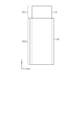
- FIG. 1 is a perspective view showing an example of the appearance of the air purifier according to Embodiment 1.
- FIG. 1 is a perspective view showing an example of the internal configuration of the air purifier according to Embodiment 1.
- FIG. FIG. 2 is a cross-sectional view schematically showing an example of the internal configuration of the air cleaner according to Embodiment 1; The perspective view which shows an example of the external appearance structure of an air cleaner typically.
- FIG. 2 is a perspective view schematically showing an example of the configuration of the air duct configuration area of the air cleaner according to Embodiment 1.
- FIG. FIG. 4 is a diagram schematically showing the positional relationship between the suction port and the discharge type dust collection device in the air cleaner according to Embodiment 1;
- FIG. 2 is a top view showing an example of the fan casing of the air purifier according to Embodiment 1; 1 is a perspective view schematically showing an example of an internal configuration of an air purifier according to Embodiment 1;
- FIG. FIG. 2 is a diagram showing an example of the configuration of a power wire connecting portion in the air cleaner according to Embodiment 1;
- FIG. 4 is a diagram schematically showing a state in which a terminal block cover is put on the power wire connecting portion of the air cleaner according to Embodiment 1;
- FIG. 4 is a top view schematically showing the state of the vicinity of the power wire insertion portion covered with the terminal block cover of the power wire connection portion of the air cleaner according to Embodiment 1;
- FIG. 4 is a side view schematically showing the state of the vicinity of the power wire insertion portion covered with the terminal block cover of the power wire connection portion of the air cleaner according to Embodiment 1;
- FIG. 2 is a perspective view schematically showing an example of the configuration of the air filter of the air purifier according to Embodiment 1;
- FIG. 2 is a perspective view showing an example of the structure of the filter fixing portion of the air purifier according to Embodiment 1;
- FIG. 2 is a perspective view showing an example of the structure of the filter fixing portion of the air purifier according to Embodiment 1;
- FIG. 4 shows an example of how the air filter is removed from the housing body in the air purifier according to Embodiment 1;
- FIG. 4 shows an example of how the air filter is removed from the housing body in the air purifier according to Embodiment 1;
- FIG. 1 is a perspective view showing an example of the appearance of an air purifier according to Embodiment 1.
- FIG. 1 the perspective view which looked at the air cleaner 1 from upper direction is shown.
- the air purifier 1 can be installed on the wall surfaces 501 and 502 or the ceiling surface, and is a device that cleans the indoor air by removing contamination from the indoor air.
- the air cleaner 1 has a housing 10 that constitutes the outer shell of the air cleaner 1 .
- the housing 10 has a rectangular parallelepiped shape.
- the surface on which the housing 10 is installed on the wall surface 501 is referred to as a rear surface 11a, and the surface opposite to the rear surface 11a is referred to as a front surface 11b.
- the surface facing the ceiling surface provided vertically upward in the room is defined as an upper surface 11c, and the surface facing the floor surface provided vertically downward in the room is defined as a lower surface 11d.
- Sides 11e and 11f are surfaces perpendicular to the rear surface 11a, the front surface 11b, the upper surface 11c, and the lower surface 11d.
- the side surface 11e corresponds to the first surface
- the upper surface 11c corresponds to the second surface.
- the rear surface 11a corresponds to the third surface
- the front surface 11b corresponds to the fourth surface.
- the direction parallel to the floor surface of the room is the X direction
- the direction perpendicular to the floor surface of the room is the Z direction
- the direction perpendicular to the wall surface 501. is the Y direction.
- the X, Y and Z directions are orthogonal to each other.
- the Y direction corresponds to the first direction
- the Z direction corresponds to the second direction
- the X direction corresponds to the third direction.
- the housing 10 has a rectangular parallelepiped shape whose Y-direction dimension is smaller than its X- and Z-direction dimensions.
- the housing 10 is made of resin, for example.
- the X direction is also referred to as the width direction of the air cleaner 1 and the housing 10
- the Y direction is also referred to as the depth direction of the air cleaner 1 and the housing 10
- the Z direction is the direction of the air. It is also referred to as the height direction of the purifier 1 and housing 10 .
- two relative positional relationships in the Y direction are expressed using “front” or “back”, and two relative positional relationships in the Z direction are expressed as “upper” or “lower”. ” is used.
- the housing 10 has a housing body 11 and a front panel 12 .
- the housing main body 11 has a hollow rectangular parallelepiped shape, and has a configuration in which a front surface 11b is opened.
- each component constituting the air purifier 1, which will be described later, is arranged in the inside of the housing body 11.
- the housing body 11 has a suction port 13, which is an opening for sucking indoor air into the interior of the housing 10, on a side surface 11e.
- the housing body 11 has a blowout port 14 on the upper surface 11c, which is an opening for blowing out the air cleaned inside the housing 10 to the outside of the housing 10.
- FIG. 1 shows the case where the upper surface 11c is adjacent to the side surface 11e.
- the rear surface 11a, upper surface 11c, lower surface 11d, and side surfaces 11e and 11f of the housing 10 are the same as the rear surface 11a, upper surface 11c, lower surface 11d, and side surfaces 11e and 11f of the housing body 11. conduct.
- the front panel 12 is a member that covers the opening provided on the front surface 11 b of the housing body 11 . By removing the front panel 12 from the housing body 11, access to each component housed inside the housing body 11 becomes possible.
- the air purifier 1 is installed on the wall surface 501 via mounting brackets (not shown) with the rear surface 11a of the housing 10 facing the wall surface 501 and the air outlet 14 facing the ceiling surface.
- the reason why the installation bracket is necessary for installing the air purifier 1 on the wall surface 501 is as follows. The first reason is that by widening the fixing range between the air cleaner 1 and the wall surface 501, the screw fixation between the air cleaner 1 and the wall surface 501 is strengthened. The second reason is that in order to install the air cleaner 1 on the wall surface 501 in an appropriate posture without tilting, it is necessary to fix the air cleaner 1 with screws with high accuracy.
- the fixing position of the air cleaner 1 should be determined with high accuracy using the mounting bracket, which is a lightweight component.
- the reason why the installation bracket is necessary for installing the air purifier 1 on the wall surface 501 is that the air purifier 1 can be installed with high precision without any fear of rattling or coming off, and without deviation of the installation position and installation angle. This is for facilitating installation.
- FIG. 2 is a perspective view showing an example of the internal configuration of the air cleaner according to Embodiment 1
- FIG. 3 is a cross-sectional view schematically showing an example of the internal configuration of the air cleaner according to Embodiment 1. is.
- FIG. 2 shows a state in which the front panel 12 of the air cleaner 1 shown in FIG. 1 is removed.
- FIG. 3 shows a cross-sectional view taken along the line III-III of FIG. 1 and parallel to the XY plane.
- some hatching is omitted for easy understanding.
- the inside of the housing 10 is mainly divided into two areas in the X direction.
- the two regions are an air passage configuration region R1 and a circuit arrangement region R2.
- the housing 10 has an air passage wall 111 that separates the air passage configuration region R1 and the circuit arrangement region R2.
- the air cleaner 1 includes a blower 21, a dust removal filter 22, a discharge type dust collection device 23, and an air filter 24 in an air passage configuration area R1 inside the housing 10.
- the blower 21 is housed in the housing 10, sucks air from the suction port 13, and generates an air flow 45 that blows air from the blowout port 14.
- the blower 21 is arranged in the center of the inside of the housing body 11 in the X direction.
- Blower 21 has fan 211 , electric motor 212 that rotates fan 211 , and fan casing 213 that houses fan 211 and electric motor 212 .
- the blower 21 is a centrifugal blower in which the air sucking direction and the air blowing direction are perpendicular to each other.
- the blower 21 is arranged such that the rotating shaft of the electric motor 212 is perpendicular to the rear surface 11 a of the housing body 11 .
- the fan casing 213 has a suction port 213a on the front face 11b side of the housing body 11 and an air outlet (not shown) on the top face 11c side of the housing body 11 .
- the fan casing 213 is arranged inside the housing body 11 so that the position of the air outlet (not shown) matches the position of the air outlet 14 of the housing body 11 .
- the fan casing 213 is arranged centrally on the rear surface 11a inside the housing body 11 in the X direction.
- the Z-direction size of the fan casing 213 is substantially the same as the Z-direction size of the inside of the housing body 11 .
- the size of the fan casing 213 in the Y direction is smaller than the size of the inside of the housing 10 in the Y direction. That is, a space 41 is formed between the front panel 12 of the housing 10 and the suction port 213 a of the fan casing 213 .
- the space 41 and a space 42 between the suction port 13 of the housing body 11 and the side surface of the fan casing 213 on the side of the suction port 13 form an air passage 40 .
- the air passage 40 is an air passage for air intake, and constitutes a part of the air passage from the suction port 13 to the air outlet 14 .
- the air outside the housing 10 is sucked through the suction port 13 .
- the sucked air passes through the air passage 40 and is sucked into the inside of the blower 21 from the suction port 213 a of the fan casing 213 , and then through the outlet of the fan casing 213 and the outlet 14 of the housing 10 . to the outside of the housing 10.
- the blower 21 generates an air flow 45 that sucks air from the inlet 13 and blows air from the outlet 14 .
- the housing body 11 has an air passage wall 112 that guides the air sucked from the suction port 13 to the space 41 between the blower 21 and the front panel 12 on the side of the suction port 13 of the housing 10 in the fan casing 213 . have.
- the air passage wall 112 forms a slope that is not perpendicular to the rear surface 11 a so that the air from the suction port 13 is guided to the space 41 .
- the air flow 45 flowing through the air passage 40 is blocked by the air passage wall 111 so as not to flow into the circuit arrangement region R2.
- the dust removal filter 22 removes impurities such as dust in the airflow 45 sucked from the suction port 13 .
- the dust removal filter 22 filters and cleans the air flow 45 sucked into the housing 10 .
- the dust filter 22 is provided on the upstream side of the air passage 40 and on the downstream side of the suction port 13 of the housing body 11 .
- the discharge type dust collection device 23 removes impurities such as dust in the airflow 45 sucked into the housing 10 .
- the discharge-type dust collection device 23 charges various kinds of particles contained in the air sucked into the air cleaner 1, attracts them to the dust collection electrode, collects the particles, and collects them inside the housing 10. Cleans the inhaled air stream 45 .
- the discharge type dust collection device 23 has a discharge section positive electrode 231 that is a discharge electrode, a discharge section negative electrode 232 that is a dust collection electrode, and a discharge type dust collection device power supply (not shown).
- the discharge type dust collection device power supply is arranged in the circuit arrangement region R2 of the housing body 11 and connected to the discharge section positive electrode 231 and the discharge section negative electrode 232 via wiring.
- positively charged ions are generated by corona discharge.
- the fine particles floating in the surroundings, which become positively charged by combining with the positively charged ions, are attracted to the negatively charged discharge section negative electrode 232 and adhere and accumulate, thereby purifying the air. be done.
- the air filter 24 removes impurities such as dust in the airflow 45 sucked from the suction port 13 .
- the air filter 24 filters and cleans the airflow 45 sucked into the interior of the housing 10 .
- the air filter 24 is arranged downstream of the discharge dust collection device 23 .
- the air filter 24 is arranged adjacent to the suction port 13 of the blower 21 so as to overlap with the blower 21 in the Y direction.
- the air filter 24 is provided so that the filter surface, which is the surface through which the air of the air filter 24 passes, perpendicularly intersects the Y direction, which is the rotational axis of the blower 21 .
- vertical includes not only the case of strictly 90 degrees but also the case of 90 degrees within a margin of error.
- the air filter 24 is supported by the housing body 11 .
- a structure in which the air filter 24 is supported by the housing body 11 will be described later.
- air filter 24 is a non-woven filter using a non-woven material.
- An example of a non-woven fabric filter is a HEPA filter (High Efficiency Particulate Air Filter).
- the air purifier 1 includes a power wire connection portion 31 and a control circuit portion 32 in a circuit layout area R2 inside the housing 10.
- the power wire connection portion 31 is a connection portion to which a power cable 51 that takes in power of the air cleaner 1 from an external power source (not shown) of the air cleaner 1 is connected.
- An example of the power cable 51 is a vinyl insulated vinyl sheathed (Flat-type: VVF) cable.
- the control circuit unit 32 includes a control circuit that controls the operation of the air cleaner 1, that is, a control circuit that controls the operation of electrical components mounted on the air cleaner 1.
- the electrical components mounted on the air cleaner 1 include the electric motor 212 of the blower 21 and other electrical components.
- Examples of electrical components are a display light emitting diode (LED), an operation switch, a remote control light receiving part, a sensor, and a discharge type dust collection device power supply.
- LED display light emitting diode
- operation switch a remote control light receiving part
- sensor a sensor
- discharge type dust collection device power supply a discharge type dust collection device power supply.
- the display LED functions as a display unit that displays various information related to the operation of the air cleaner 1, such as the air volume during operation of the air cleaner 1 and the degree of contamination of indoor air.
- the operation switch is an operation unit for performing operations such as turning on or off the power of the air cleaner 1, operating air volume of the air cleaner 1, and switching the air cleaner 1 between an automatic operation mode and a manual operation mode.
- the sensor is a detection unit that detects the air quality of indoor air, such as dust, odor, and the degree of contamination such as carbon dioxide (CO 2 ) in the indoor air.
- the discharge type dust collection device power supply is a power supply unit that supplies high voltage power for discharging to the discharge type dust collection device 23 .
- Air Path Configuration Region R1 As shown in FIGS. 2 and 3, the blower 21 is arranged substantially in the center of the inside of the housing 10 in the X direction. A suction port 13 is provided on a side surface 11e of the housing body 11 on one side in the X direction when viewed from the blower 21 .
- the dust filter 22 and the discharge type dust collection device 23 are arranged between the suction port 13 and the blower 21 in the X direction. Specifically, the dust removal filter 22 and the discharge type dust collection device 23 are arranged in the space 42 between the suction port 13 inside the housing body 11 and the side surface of the blower 21 on the suction port 13 side. be.
- the discharge type dust collection device 23 is arranged downstream of the dust removal filter 22 .
- the air filter 24 is arranged between the dust removal filter 22 and discharge type dust collecting device 23 and the blower 21 .
- the air filter 24 is arranged in the space 41 between the blower 21 and the front panel 12 and adjacent to the front side of the suction port 213a of the blower 21 .
- the air purifier has a discharge type dust collection device and an air filter stacked in the depth direction of the main body of the air purifier, which is the Y direction, between the suction port of the blower and the front panel. be.
- the thickness dimensions of the main body of the air purifier of the comparative example are the blower, the discharge type dust collection device, the air filter, the rear surface and the front panel of the housing main body, respectively. Add thickness.
- the thickness dimension of the main body of the air cleaner 1 is , the thicknesses of the air filter 24, the space 41 forming the air passage 40, the rear surface 11a of the housing body 11, and the front panel 12 are added. Since the size in the depth direction of the space 41 serving as the air passage 40 can be made smaller than that of the discharge type dust collection device 23, the size in the depth direction of the main body of the air cleaner 1 according to Embodiment 1 can be compared. It can be smaller than the example air purifier. As an example, the thickness dimension of the main body of the air cleaner 1 can be changed from 180 mm in the comparative example to 170 mm in the first embodiment.
- the air purifier 1 can reduce the dimension of the housing 10 in the depth direction. As a result, the space occupied by the air purifier 1 in the room can be reduced, and the indoor air can be cleaned while reducing the feeling of oppression given to people in the room, thereby providing a comfortable air environment space. becomes possible.
- an air cleaner having an indoor air suction port 13 on the lower surface 11d of the housing 10 facing the floor surface is assumed.
- a floor covering made of fiber material such as a carpet is placed on the floor below the air purifier 1 installed on the wall surface 501 . Since a large amount of fibrous material is generated from the rug during use, the air purifier 1 having the indoor air suction port 13 on the lower surface 11d of the housing 10 facing the floor surface contains a large amount of fibrous material together with the indoor air. will be inhaled. For this reason, clogging of the dust filter 22 and the discharge type dust collection device 23 is caused by a fibrous material much larger than the amount of dust in the air, which is the original target of dust collection. As a result, extra periodic maintenance of the dust filter 22 and the discharge type dust collecting device 23 is required.
- the suction port 13 is arranged on the side surface 11e of the housing 10 facing the floor surface, not the bottom surface 11d.
- the air purifier 1 having such a configuration, it is difficult to suck in the fibers of the carpet through the suction port 13 compared to an air purifier having an indoor air suction port on the lower surface 11 d of the housing 10 . Therefore, unnecessary periodic maintenance of the dust removal filter 22 and the discharge type dust collection device 23 due to absorption of fibers of the rug is unnecessary.
- the air purifier 1 since the air purifier 1 is installed on the wall surface 501, no floor space is required for installing the air purifier 1. In addition, since the air cleaner 1 does not stack the discharge type dust collection devices 23 in the depth direction of the housing 10, compared to the case where the discharge type dust collection devices 23 are stacked in the depth direction of the housing 10, Therefore, the thickness of the air purifier 1 can be reduced, and the projection dimension from the wall surface 501 is also reduced. As a result, it is possible to enhance the effect of reducing the oppressive feeling given to people in the room. Also, the air cleaner 1 installed on the wall surface 501 is separated from the carpet on the floor surface.
- the air purifier 1 in which the suction port 13 is provided on the side surface 11e of the housing 10 facing the floor surface instead of the bottom surface 11d has the dust removal filter 22 and the discharge type dust collection device 23 that are caused by the fiber material of the carpet. Clogging can be suppressed as compared with an air purifier in which a suction port is provided on the lower surface 11d of the housing 10 facing the floor surface.
- the air passage wall 111 separates the air passage configuration region R1 and the circuit arrangement region R2. Further, the circuit arrangement region R2 is arranged inside the housing 10 on the opposite side of the air blower 21 from the suction port 13 in the X direction, that is, on the side surface 11f side. Therefore, it is possible to separate the power wire connecting portion 31 and the control circuit portion 32 through which a large current value flows from the air passage 40 .
- the electric parts through which a large current flows are the power wire connection portion 31, the control circuit portion 32, and the electric motor 212 of the blower 21.
- the power wire connection portion 31 and the control circuit portion 32 among these are located in a circuit arrangement region which is a region inside the housing 10 on the opposite side of the air inlet 13 across the blower 21 in the X direction. Located on R2. Also, the circuit arrangement region R2 is partitioned from the air passage configuration region R1 by the air passage wall 111. As shown in FIG. For this reason, inside the housing 10 , electrical components through which a large current flows are separated from the air passage 40 starting from the suction port 13 .
- the electric motor 212 of the blower 21 is housed inside the fan casing 213 and is separated from the air passage 40 from the suction port 13 to the suction port 213 a of the blower 21 .
- the electric parts through which a large current flows are separated from the air passage 40, so that it is possible to greatly suppress deterioration in insulation in the electric parts.
- a HEPA filter or the like using a non-woven fabric material is often used for the air filter 24 generally used in the air purifier 1.
- a non-woven fabric filter collects dust based on the principle of inertial collision with dust, and therefore has a large pressure loss.
- dust or the like adheres to the air filter 24 during use, it blocks the passage of air, resulting in a further increase in pressure loss and requiring replacement of the air filter 24 at regular intervals.
- the discharge type dust collection device 23 collects dust using the coulomb force of electricity, so the air path is large and the pressure loss is small. Also, the adhesion of dust and the like due to use is limited to the surface of the electrode plate constituting the negative electrode 232 of the discharge section. Therefore, the increase in pressure loss due to adhesion of dust or the like is extremely small compared to the air filter 24, and does not affect the air blowing performance.
- the discharge type dust collection device 23 removes dust and the like in the air flow 45, and the dust and the like reaching the air filter 24 is removed. amount can be reduced. As a result, clogging of the air filter 24 is suppressed, and an increase in pressure loss of the air filter 24 due to clogging can be suppressed.
- ionized substances are also emitted from the discharge type dust collection device 23, and it is known that these ionized substances have the effect of decomposing odorous components and suppressing the propagation of viruses, microorganisms, and the like. Therefore, by arranging the discharge type dust collection device 23 on the windward side of the air filter 24, the ionized substances emitted from the discharge type dust collection device 23 reach the leeward air filter 24 and adhere to the air filter 24. It is possible to decompose odorous components and suppress propagation of viruses, microorganisms, and the like.
- the discharge type dust collection device 23 can remove most of the dust in the air flow 45.
- the ionized substances emitted from the discharge type dust collection device 23 reach the air filter 24, thereby suppressing decomposition of odorous components adhering to the air filter 24 and propagation of viruses, microorganisms, and the like.
- the replacement maintenance period of the air filter 24 is made longer than when the discharge type dust collection device 23 is not provided or when the discharge type dust collection device 23 is not arranged on the windward side of the air filter 24. be able to.
- maintenance, specifically cleaning, of the discharge type dust collection device 23 is performed by washing the electrode plate that constitutes the discharge section negative electrode 232 with water. By washing the electrode plate with water, dust and the like adhering to the surface of the electrode plate are removed. Since the electrode plate that has been washed with water can be used repeatedly, it is not necessary to replace the electrode plate that constitutes the discharge negative electrode 232 in the discharge type dust collecting device 23 .
- the blower 21 used in the air cleaner 1 according to Embodiment 1 is a centrifugal blower in which the blowing direction is at 90 degrees with respect to the suction direction.
- the centrifugal blower draws in air from a suction port 13 on the side surface 11e perpendicular to the X direction and blows air from a blowout port 14 on the top surface 11c perpendicular to the Z direction.
- the suction port 13 is provided on the side surface 11e perpendicular to the width direction, which is the X direction, and the outlet port 14 is provided on the upper surface 11c, which is perpendicular to the height direction which is the Z direction. It is shown.
- the direction of the air outlet of the fan casing 213 is directed upward, so that the air flow of the blower 21 can be made to flow toward the upper surface 11c in the Z direction.
- the wall-mounted air purifier 1 with improved blowing performance such as noise and power consumption without excessive pressure loss compared to the case of using an axial flow fan.
- the air cleaner 1 is attached to the wall surface 501 by providing the air outlet 14 in the center of the upper surface 11c of the housing 10 in the X direction. It is possible to prevent wall contamination on another wall surface 502 perpendicular to the X direction orthogonal to the .
- FIG. 4 is a perspective view schematically showing an example of the external configuration of the air purifier.
- Air purifier 100 shown in FIG. 4 is provided with outlet 14 on upper surface 11c of housing 10, and the X-direction end of outlet 14 is located near the X-direction end of upper surface 11c. positioned. The air blown out from the blow-out port 14 flows by taking in surrounding air after being blown out. As shown in FIG.
- the blower outlet 14 extends to the end in the X direction, that is, near the end in the width direction of the housing 10 , the blown air continues to hit the wall surface 502 for a long period of time.
- the side walls 502 of the purifier 1 may become dirty.
- the dirt on the side wall surface 502 becomes conspicuous.
- the blower outlet 14 in the X direction, is provided in the center of the upper surface 11c of the housing 10, and the end of the blower outlet 14 in the X direction is located in the X direction of the upper surface 11c. If it is further away than the end, the distance between the X-direction end of the outlet 14 and the side wall surface 502 is longer than in FIG. In other words, by arranging the outlet 14 in the center of the upper surface 11 c in the X direction, the end of the outlet 14 in the X direction is separated from the side wall surface 502 . Even if the distance between them is short, it is difficult for the blown air to reach the wall surface 502 on the side of the air cleaner 1 . Therefore, it is possible to suppress contamination of the side wall surface 502 of the air cleaner 1 caused by the continuous blowing air against the side wall surface 502 of the air cleaner 1 .
- the length from the end of the housing 10 to the end of the air outlet 14 in the X direction varies depending on the size of the housing 10 in the X direction, the wind speed of the air blown from the air outlet 14, etc. It is desirable that the length be such that the air blown from the air outlet 14 does not reach the position corresponding to the end of the housing 10 .
- the air outlet 14 in the center of the upper surface 11c of the housing 10 in the X direction, it is possible to suppress wall stains on the wall surfaces on either side of the air cleaner 1 in the X direction. It is possible. Furthermore, when the air purifier 1 is installed on the wall surface 501, by tilting the blowing direction of the blowing air forward from the Z direction, the blowing air can be prevented from hitting the wall surface 501 on which the air purifier 1 is installed. As a result, dirt on the wall surface 501 on which the air cleaner 1 is installed can be suppressed.
- the outlet 14 is provided on the upper surface 11c of the housing 10 is shown, but it may be provided on the lower surface 11d.
- the air blown out from the housing 10 does not stain the ceiling surface.
- the outlet 14 on the lower surface 11d of the housing 10 compared to the case of providing it on the upper surface 11c, foreign matter such as dust settling down from above the air cleaner 1 when the operation of the air cleaner 1 is stopped is prevented. can be suppressed from flowing into the housing 10 .
- FIG. 5 is a perspective view schematically showing an example of the configuration of the air duct configuration area of the air purifier according to Embodiment 1.
- FIG. FIG. 6 is a diagram schematically showing the positional relationship between the suction port and the discharge type dust collection device in the air cleaner according to Embodiment 1.
- FIG. The same reference numerals are given to the same components as those in the above drawings, and the description thereof will be omitted. For the sake of explanation, illustration of the dust removal filter 22 is omitted in FIG.
- the discharge type dust collection device 23 is not provided so as to overlap the entire surface of the suction port 13 provided in the side surface 11 e of the housing 10 , but is provided so as to partially overlap the suction port 13 . Specifically, as shown in FIG. 6, the discharge type dust collection device 23 does not overlap the first region R11 above the suction port 13 in the Z direction, and the remaining first region R11 except the first region R11 does not overlap. It is arranged so that it may overlap with suction port 13 in 2 fields R12. Therefore, the size of the discharge type dust collection device 23 is equal to or larger than the size of the suction port 13 in the Y direction, which is the depth direction, and the size of the discharge type dust collection device 23 is equal to or larger than the size of the suction port 13 in the Z direction.
- the first region R ⁇ b>11 above the suction port 13 in the Z direction does not overlap the discharge type dust collection device 23 .
- the area of the discharge type dust collection device 23 perpendicular to the X direction overlaps with the area of a part of the suction port 13.
- the first region R11 above the suction port 13 in the Z direction is By arranging the discharge type dust collection device 23 so that it does not overlap and overlaps in the remaining second region R12, the pressure loss is low, the air filter 24 is less likely to clog, noise is low, and the maintenance period is long.
- the air purifier 1 can be used for a long period of time.
- FIG. 7 is a top view showing an example of the fan casing of the air cleaner according to Embodiment 1.
- fan casing 213 has scroll portion 2131 and diffuse portion 2132 .
- the scroll part 2131 is a part that is arranged around the fan 211 and forms a spiral flow path whose width in the radial direction increases toward the downstream side of the air flow.
- the diffuse portion 2132 is a portion on the downstream side of the scroll portion 2131 and constitutes a flow path between the scroll portion 2131 and the outlet 14 of the housing body 11 .
- the suction port 213 a is provided on the front surface of the scroll portion 2131 .
- the outlet is provided at the downstream end of the diffuser 2132 (not shown).
- the fan casing 213 has an outer peripheral wall 2133 forming a scroll portion 2131 and a diffuse portion 2132 . 5 and 7, the position of the outer peripheral wall 2133 is indicated by broken lines.
- the opening is narrower than the outlet. That is, the outer peripheral wall 2133 of the fan casing 213 has a tongue portion 2134 near the boundary between the scroll portion 2131 and the diffuser portion 2132, in which one outer peripheral wall 2133a protrudes toward the other outer peripheral wall 2133b.
- the tongue 2134 guides the airflow swirling inside the fan casing 213 to the outlet. As shown in FIG. 7, when the airflow is blown upward in the Z direction, the tongue 2134 is arranged on the upper side of the fan casing 213 in the Z direction. Therefore, the center C1 of the suction port 213a of the blower 21 is located below the center C2 of the housing 10 in the Z direction, which is the height direction.
- the center C2 of the air filter 24 and the center C2 of the housing 10 are at substantially the same position in the Z direction. Therefore, the center C1 of the suction port 213a of the blower 21 is located below the center C2 of the air filter 24 in the Z direction.
- the center C1 of the suction port 213a of the blower 21 in the Z direction is biased below the center C2 of the air filter 24 . Therefore, in the Z direction, the wind speed below the air filter 24 is higher than that above it. As a result, since it is difficult to achieve a uniform wind speed over the entire surface of the air filter 24, the pressure loss increases. In addition, the clogging of the air filter 24 is also biased toward the lower portion of the air filter 24 where the wind speed increases, shortening the maintenance period.
- the discharge type dust collection device 23 has a pressure loss although it has a small area.
- the discharge type dust collection device 23 when the discharge type dust collection device 23 is arranged so as to overlap the second region R12 of the suction port 13 of the housing 10, the air sucked from the suction port 13 varies depending on the position in the Z direction.
- There is an imbalance in the intake air volume which is the amount of In FIG. 5, the intake air volume in the airflow 45-11 passing through the first region R11 of the suction port 13 is larger than the intake air volume in the airflow 45-12 passing through the second region R12.
- the wind velocity passing through the air filter 24 can be made uniform. That is, the wind speed can be uniform over the entire surface of the air filter 24 .
- the wind speed increases at the position corresponding to the formation position of the scroll portion 2131, and the wind speed decreases at the position corresponding to the diffuse portion 2132.
- the discharge type dust collection device 23 it is desirable to provide the discharge type dust collection device 23 at a position corresponding to the formation position of the scroll portion 2131 in the suction port 13 of No. 10 . That is, in the Z direction, it is desirable that the formation position of the diffuse portion 2132 or the tongue portion 2134 corresponds to the first region R11, and the formation position of the scroll portion 2131 corresponds to the second region R12. Corresponding the second region R12 to the formation position of the scroll portion 2131 is equivalent to making the center of the discharge type dust collection device 23 substantially the same as the center C1 of the suction port 213a of the blower 21 in the Z direction. .
- the amount of air drawn into the suction port 13 of the housing 10 is reduced due to the pressure loss in the discharge type dust collection device 23 when passing through the discharge type dust collection device 23 in the second region R12.
- Stream 45 - 12 flows into the air filter 24 at a position corresponding to the formation position of the scroll portion 2131 .
- the air flow 45-11 is the diffuse air of the air filter 24. It flows into a position corresponding to the formation position of part 2132 .
- the wind speed is lower than at the position corresponding to the forming position of the scroll portion 2131 .
- the wind speed of the air flow 45-11 flowing into the position corresponding to the formation position of the diffuse portion 2132 of the air filter 24 the wind speed of the air flow 45-12 flowing into the position corresponding to the formation position of the scroll portion 2131, will be approximately equal and will be homogenized.
- the discharge type dust collecting device 23 it is desirable not to place the discharge type dust collecting device 23 at the position corresponding to the formation position of the tongue 2134 of the fan casing 213 .
- the discharge The height of the dust collecting device 23 can be 238 mm. With such dimensions, the air velocity is uniform over the entire surface of the air filter 24, so the pressure loss of the air filter 24 is low, and clogging of the air filter 24 is less likely to occur. In addition, noise can be suppressed, and compared to the case where the discharge type dust collection device 23 is arranged on the entire surface of the suction port 13 of the housing 10, the air cleaner 1 can be provided with a longer maintenance period. .
- FIG. 8 is a perspective view schematically showing an example of the internal configuration of the air cleaner according to Embodiment 1.
- FIG. 8 the same code
- illustration of the air filter 24 is omitted.
- the air purifier 1 has a power wire connection portion 31 and a control circuit portion 32 in the circuit arrangement region R2 of the housing body 11 .
- the power wire connecting portion 31 is arranged in the lower region of the circuit layout region R2, and the control circuit portion 32 is arranged in the upper region.
- FIG. 9 is a diagram showing an example of the configuration of the power wire connecting portion in the air purifier according to Embodiment 1.
- FIG. 9 the arrangement position of the power cable 51 is indicated by a two-dot chain line, and the power cable 51 is actually arranged at the position indicated by the two-dot chain line.
- the power cable connection portion 31 is connected with a power cable 51 routed from the rear surface 11 a facing the wall surface 501 inside the housing 10 .
- the power wire connection portion 31 has a power wire insertion portion 311 , a power wire connection terminal block 312 , and a terminal block accommodation portion 313 .
- the power wire insertion portion 311 is arranged adjacent to the terminal block housing portion 313 inside the housing body 11 .
- the power wire insertion portion 311 is a member that protrudes from the rear surface 11a of the housing body 11 toward the front surface 11b inside the housing body 11 and allows the power cable 51 to be inserted therein.
- the power wire insertion portion 311 has an opening 115 at one end, which is a connection portion with the rear surface 11 a of the housing 10 , and an opening 335 for pulling out the power cable 51 at the other end.
- the opening 115 penetrates the rear surface 11 a of the housing body 11 .
- the power wire insertion portion 311 is connected to an opening 115 that penetrates the rear surface 11a of the housing 10, protrudes toward the front surface 11b of the housing 10, and has an opening 335 for drawing out the power cable 51 to the power wire connection terminal block 312. have.
- Aperture 115 corresponds to the first aperture and aperture 335 corresponds to the second aperture.
- the length of the power wire insertion portion 311 is greater than or equal to the length of the terminal block housing portion 313 .
- the power wire insertion portion 311 is a concave member with an open surface facing the terminal block accommodating portion 313 .
- the power wire insertion portion 311 has a function of guiding the power cable 51 inserted through the opening 115 of the rear surface 11 a of the housing 10 to the terminal block housing portion 313 .
- the example of FIG. 9 has a structure in which a pair of wall portions 331 are formed so as to protrude from the wall portion 333 in the X direction at both ends in the Z direction of the wall portion 333 provided on the side surface 11f. As shown in FIG.
- the power wire insertion portion 311 has a support portion 332 inside the wall portions 331 and 333 for supporting a terminal block cover 342 of the power wire connection terminal block 312, which will be described later.
- the front end portion of the support portion 332 is positioned so that the terminal block cover 342 is positioned below the front end portion of the power wire insertion portion 311 when the terminal block cover 342 is put thereon.
- the power wire insertion portion 311 is made of resin, for example.
- the power line connection terminal block 312 is a member that electrically connects the power cable 51 drawn from the external power source and the power line 321 drawn from the control circuit section 32 .
- the power line connection terminal block 312 is fixed inside the terminal block accommodating portion 313 .
- the terminal block accommodating portion 313 covers the periphery of the power line connection terminal block 312 , accommodates the power line connection terminal block 312 , and is fixed to the housing 10 .
- the terminal block housing portion 313 has a housing body 341 having an opening at least on the front surface in the Y direction, and a terminal block cover 342 that closes the front opening of the housing body 341 .
- the terminal block accommodating portion 313 is made of sheet metal, for example.
- the housing section main body 341 has a rectangular rear surface 341a, two side surfaces 341b and 341c perpendicular to the X direction, and perpendicular to the Z direction, and is on the opposite side of the control circuit section 32 in the Z direction.
- the housing portion main body 341 On the rear surface 341a of the housing portion main body 341, there are provided a circuit-side power wire arrangement region R21 in which the power wire 321 from the control circuit portion 32 is routed, and a power cable arrangement region R21 in which the power cable 51 from the power wire insertion portion 311 is routed.
- the power line connection terminal block 312 is arranged so as to secure the arrangement region R22.
- an L-shaped power cable arrangement region R22 is provided from the power wire insertion portion 311 to the power wire connection terminal block 312 .
- the terminal block housing portion 313 has a power wire fixing portion 345 for fixing the power cable 51 in the power cable arrangement region R22.
- the power cable 51 is arranged horizontally from the power wire insertion portion 311 to the power wire fixing portion 345 . is placed at a position where it is arranged in the vertical direction.
- the power cable 51 is inserted from the outside into the opening 115 of the rear surface 11 a of the housing 10 and pulled out from the opening 335 of the power wire insertion portion 311 to the housing portion main body 341 .
- the accommodation portion main body 341 it is drawn out to the power cable arrangement region R ⁇ b>22 and connected to the power line connection terminal block 312 .
- the power cable 51 is arranged by the power cable fixing portion 345 in an L shape having a portion arranged in the X direction and a portion arranged in the Z direction.
- the terminal block cover 342 is a member that covers the opening 335 of the power wire insertion portion 311 and the power wire connection terminal block 312 .
- the terminal block cover 342 covers the power wire insertion portion 311 and the accommodation portion main body 341 .
- FIG. 10 is a diagram schematically showing a state in which a terminal block cover is put on the power wire connecting portion of the air cleaner according to Embodiment 1.
- FIG. The terminal block cover 342 has a plate-like terminal block cover portion 342 a covering an area including the power wire connection terminal block 312 and an insertion portion cover portion 342 b covering the opening 335 of the power wire insertion portion 311 .
- the insertion portion cover portion 342b has a convex shape that protrudes outward from the outline of the terminal block cover portion 342a in the in-plane direction of the terminal block cover portion 342a.
- the terminal block cover portion 342 a is provided so as to cover the front opening of the housing portion main body 341 that houses the power line connection terminal block 312 .
- the terminal block cover portion 342a covers the front opening of the housing portion main body 341, and the insertion portion cover portion 342b is fitted into the opening 335 of the power wire insertion portion 311, so that the housing portion main body 341 and the power wire insertion portion 311 are covered.
- the terminal block cover 342 is made of sheet metal, for example.
- FIG. 11 is a top view schematically showing the state of the vicinity of the power wire insertion portion covered by the terminal block cover of the power wire connection portion of the air purifier according to Embodiment 1.
- FIG. 12 is a side view schematically showing the state of the vicinity of the power wire insertion portion covered with the terminal block cover of the power wire connection portion of the air cleaner according to Embodiment 1.
- FIG. 12 the state inside the power wire insertion portion 311 is indicated by dotted lines.
- the insertion portion cover portion 342b is no longer pushed toward the rear surface 11a of the housing 10 .
- the terminal block cover portion 342 a contacts the upper end portions of the side surfaces 341 b , 341 c , and 341 d of the housing portion main body 341 .
- the terminal block cover 342 has a structure supported by the accommodation portion main body 341 and the power wire insertion portion 311 .
- the terminal block cover 342 may cover the opening 335 of the power wire insertion portion 311 and the power wire connection terminal block 312 , and the terminal block housing portion 313 may not have the housing body 341 .
- the power line fixing portion 345 is provided on the rear surface 11 a of the housing 10 to fix the power cable 51 inside the housing 10 .
- the shape of the opening 335 of the power wire insertion portion 311 includes a wall portion 333 perpendicular to the X direction when viewed from the Y direction, which is the extending direction of the power wire insertion portion 311 , It has a concave shape surrounded by a wall portion 331 perpendicular to the Z direction.
- the insertion portion cover portion 342b is held by adopting a structure in which the insertion portion cover portion 342b having a convex shape is sandwiched between the openings 335 of the power wire insertion portion 311 having such a concave shape.
- the terminal block cover 342 is positioned perpendicular to the floor surface, but does not easily come off the terminal block accommodating portion 313 . Further, by surrounding the convex insertion portion cover portion 342b in the opening 335 of the concave power wire insertion portion 311, the side surface of the insertion portion cover portion 342b can be prevented from being exposed.
- the power supply cable 51 is inserted from the wall surface 501 facing the rear surface 11a of the housing 10 through the opening 115 provided in the rear surface 11a, and pulled out from the opening 335 via the power supply wire insertion portion 311. It is connected to the line connection terminal block 312 . As a result, the power cable 51 can be guided to the power line connection terminal block 312 without protruding from the rear surface 11 a of the housing 10 . That is, it is possible to improve the appearance when the air cleaner 1 is installed on the wall surface 501 .
- the power wire insertion portion 311 is provided so that the opening 335 of the power wire insertion portion 311 penetrates the opening 115 provided in the rear surface 11a of the housing 10, workability of laying the power cable 51 is improved. be able to. Furthermore, after the connection of the power cable 51 to the power wire connection terminal block 312 is completed, the terminal block cover 342 covers the power wire connection terminal block 312 and the power wire insertion portion 311, which is a simple structure. , the operator or the like can be prevented from accidentally touching the power cable 51 .
- the power cable 51 is passed through the ceiling space and pulled out from an opening in the wall surface 501 facing the rear surface 11a of the housing 10 of the air cleaner 1 .
- the power cable 51 pulled out in this way is routed from the opening of the wall surface 501 to the side face 11f or the front face 11b of the housing 10 of the air cleaner 1 and connected inside the main body of the air cleaner 1, the power cable 51 is connected. Not only does it look bad because it is exposed, but there is also the possibility that the power cable 51 will be damaged.
- Embodiment 1 as shown in FIG.
- the power cable 51 is inserted through the opening 115 and pulled out to the power wire connection terminal block 312 through the opening 335 of the power wire insertion portion 311 .
- the power wire insertion portion 311 is a recessed member that protrudes in the depth direction, and is equivalent to a state in which the power wire insertion portion 311 penetrates from the rear surface 11a of the housing 10 to a position adjacent to the power wire connection terminal block 312 and is opened. Become. Therefore, the visibility of the power cable 51 is improved, and resistance between the power cable 51 and the housing 10 does not occur when the power cable 51 is routed, resulting in excellent workability.
- the terminal block cover 342 is provided with a terminal block cover portion 342a covering an area where the power wire connection terminal block 312 is installed, and a projecting insertion portion cover portion 342b covering the power wire insertion portion 311. was used to cover the terminal block housing portion 313 and the power wire insertion portion 311 .
- an insertion portion cover portion 342b corresponding to the power wire insertion portion 311 is provided in a form projecting in the in-plane direction from the terminal block cover portion 342a.
- the terminal block cover 342 is generally made of sheet metal.
- the wall portions 331 and 333 of the concave power wire insertion portion 311 surround the insertion portion cover portion 342b. covered. In this state, it is possible to prevent the operator or the user from touching the end surface of the insertion portion cover portion 342b, which is a protrusion.
- the terminal block cover 342 made of sheet metal it is possible to have a function of preventing the spread of fire even when the power wire connecting portion 31 catches fire.
- the effect compared with the case where the power cable 51 is not arranged in an L shape in the power cable arrangement region R22 will be described. It is assumed that the power cable 51 is linearly arranged from the power wire insertion portion 311 to the power wire connection terminal block 312 . In such a case, even if the power cable 51 is fixed by a fixing member such as a clip, the power cable cannot be connected when tension that pulls or pushes the power cable 51 is applied. A load is transmitted to the portion 31, which causes loosening of the power wire connection portion 31 fixed to the housing 10. - ⁇ If the power wire connecting portion 31 becomes loose, there is a possibility of poor contact.
- the terminal block housing portion 313 has the power cable 51 between the power wire insertion portion 311 and the power wire connection terminal block 312 in the power cable arrangement region R22. is arranged in the X direction, that is, in the horizontal direction, and the power cable 51 is arranged in the Z direction, that is, in the vertical direction. In other words, the power cable 51 is arranged at a substantially right angle at the power cable connection portion 31 . With such an arrangement of the power cable 51 , no load is transmitted to the power cable connection portion 31 even if a tension that pulls the power cable 51 or a tension that pushes the power cable 51 is applied. In other words, even if tension is applied to the power cable 51 , it does not cause loosening of the power cable connection portion 31 .
- the power line connection terminal block 312 is arranged above the power line insertion portion 311 in the Z direction. If the air purifier 1 is splashed with water, the water may reach the interior of the housing 10 along the power cable 51 . However, the portion from the power wire insertion portion 311 to the power wire fixing portion 345 is horizontal, and the portion from the power wire fixing portion 345 to the power wire connection terminal block 312 is vertical, so water does not travel upward through the vertical portion. . That is, even if the air purifier 1 is splashed with water, it is possible to prevent the water from reaching the power line connection terminal block 312 .
- FIG. 13 is a perspective view schematically showing an example of the configuration of the air filter of the air cleaner according to Embodiment 1.
- FIG. 13 the same code
- the air filter 24 is arranged on the front side of the blower 21 . Therefore, the housing 10 has an inner wall shaped to match the outer shape of the air filter 24 .
- the air filter 24 has a rectangular shape and has approximately the same size as the fan casing 213 of the blower 21 in a plane parallel to the ZX plane.
- a side surface of the air filter 24 perpendicular to the Z direction is inscribed with the upper surface 11c and the lower surface 11d of the housing 10 . Further, of the side surfaces of the air filter 24 perpendicular to the X direction, the side surface on the circuit layout region R2 side contacts the air passage wall 111 . Of the side surfaces of the air filter 24 perpendicular to the X direction, the side surface facing the suction port 13 of the housing 10 forms the air passage 40 and does not come into contact with the housing 10 . However, the housing 10 has an inner wall 117 that protrudes inward in the Z direction in a region where the blower 21 is not arranged in the air passage configuration region R1 compared to the region where the blower 21 is arranged.
- a part of the side surface of the air filter 24 on the suction port 13 side comes into contact with a wall surface 117x of the inner wall 117 perpendicular to the X direction. That is, the air filter 24 contacts the wall surface 117x at both ends in the Z direction of the side surface on the suction port 13 side.
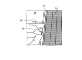
- the housing body 11 With the air filter 24 supported on the blower 21, the housing body 11 has a filter fixing portion 120 on the side of the air passage wall 111 and a wall surface 117x on the side of the suction port 13 so that the air filter 24 does not come off. and a hanging portion 131 . 7 and 8, the air filter 24 is also supported by a filter support portion 2137 provided on the fan casing 213. As shown in FIGS.
- the filter hooking portion 131 is provided on the inner wall of the housing 10 in contact with one side surface of the air filter 24 in the X direction, and fixes the position of the air filter 24 .
- the filter fixing portion 120 is provided in contact with the inner wall of the housing 10 that contacts the other side surface of the air filter 24 in the X direction, and fixes the air filter 24 .
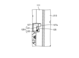
- FIG. 14 and 15 are perspective views showing an example of the structure of the filter fixing portion of the air purifier according to Embodiment 1.
- FIG. 14 shows the state with the air filter 24 attached
- FIG. 15 shows the state with the air filter 24 removed.
- the filter fixing portion 120 is supported by a support base portion 125 provided on the circuit layout region R2 side.
- the support base portion 125 is provided in contact with the air passage wall 111, which is the inner wall of the housing 10, and has a surface perpendicular to the Y direction.
- the filter fixing portion 120 is arranged on the front surface of the air filter 24 to suppress movement of the air filter 24 in the thickness direction, that is, the Y direction, and the pressing member 121 can be rotated to the support base portion 125. and a securing member 122 that secures to.
- the pressing member 121 is, for example, a rod-shaped member extending in one direction.
- the shape of the cross section perpendicular to the extending direction of the pressing member 121 is not particularly limited, and may be rectangular, circular, or polygonal.
- the fixing member 122 is a member that fixes one end of the pressing member 121 to the support base 125 so that the pressing member 121 is rotatable in a plane perpendicular to the Y direction.
- One end of the pressing member 121 is fixed to the support base portion 125 by the fixing member 122, so that the pressing member 121 is rotatable about the fixing member 122 within the ZX plane.
- a screw hole is formed at the fixing position of the pressing member 121 of the support base portion 125, and the fixing member 122 is a male screw that is screwed into this screw hole.
- the filter fixing portion 120 is configured by a lever-shaped member.
- the support base portion 125 is formed so that the front surface of the support base portion 125 is flush with the front surface of the air filter 24 when the air filter 24 is arranged on the front surface of the blower 21. .
- the housing body 11 has a filter finger hooking portion 127 which is a concave portion arranged adjacent to the filter fixing portion 120 in the Z direction.
- the concave portion of the filter finger hooking portion 127 has an open surface facing the side surface of the air filter 24 on the side of the air passage wall 111 . That is, the filter finger hooking portion 127 is formed of a concave portion adjacent to the support base portion 125 in the Z direction and directed toward the rear surface 11a. It is desirable that the concave portion forming the filter finger hooking portion 127 has a size that allows insertion of a normal adult finger. In one example, the size of the filter finger hook 127 in the Z direction is 20 mm, and the size in the X direction is 25 mm.
- the depth of the concave portion forming the filter finger hooking portion 127 is set so that the finger inserted into the concave portion can touch the side surface of the air filter 24 and does not exceed the thickness dimension of the air filter 24 .
- the depth of the recess may be 20 mm. That is, the depth of the concave portion forming the filter finger hook portion 127 is such that the side surface of the air filter 24 can be touched, and the position of the bottom surface 127a of the concave portion is closer to the front side than the position of the rear surface of the air filter 24. Become.
- the reason why the depth of the concave portion does not exceed the thickness dimension of the air filter 24 is to prevent the airflow 45 from passing through the filter finger hooking portion 127 and flowing into the blower 21 without passing through the air filter 24. It's for. By inserting a finger into the filter finger hooking portion 127 configured in this manner, the side surface of the air filter 24 can be hooked on the finger.
- the support base portion 125 and the filter finger hooking portion 127 are provided so as to protrude toward the circuit layout region R2 side. Therefore, the air passage wall 111 provided at the boundary with the circuit layout region R2 protrudes toward the circuit layout region R2 by the amount where the support base portion 125 and the filter finger hook portion 127 are disposed.
- the air passage wall 111 includes a wall portion 111a below the support base portion 125 and the filter finger hook portion 127, wall portions 111b, 111c, and 111d surrounding the support base portion 125 and the filter finger hook portion 127, and a support base. and a wall portion 111 e above the portion 125 and the filter finger hook portion 127 .
- the wall portion 111 a and the wall portion 111 b are perpendicular to each other below the filter fixing portion 120 .
- the air filter 24 is mounted parallel to the wall surface 501, that is, perpendicular to the floor surface. Therefore, the pressing member 121 is rotatable in a plane perpendicular to the floor surface. If the holding member 121 is weakly fixed by the fixing member 122, the end of the holding member 121 that is not fixed to the fixing member 122 may receive gravity and rotate downward. However, since the lower wall portion 111b surrounding the support base portion 125 and the filter finger hook portion 127 receives the pressing member 121, the pressing member 121 is prevented from moving to a position where it does not overlap the front side of the air filter 24.
- the filter hooking portion 131 is a protrusion provided on the wall surface 117x of the inner wall 117 of the housing 10 on the suction port 13 side.
- a filter hooking portion 131 is provided at a position where the side surface of the air filter 24 is sandwiched between the filter hooking portion 131 and the front surface of the fan 21 when the air filter 24 is arranged on the front surface of the fan 21 . Since the filter hooking portion 131 protrudes from the wall surface 117x toward the air passage wall 111, it has a function of suppressing movement of the air filter 24 in the Y direction.
- the attachment of the air filter 24 to the housing body 11 will be explained. While hooking one side surface of the air filter 24 on the filter hooking portion 131 of the wall surface 117x, the air filter 24 is pushed in so as to cover the front surface of the fan casing 213. - ⁇ As a result, the side surface of the air filter 24 on the suction port 13 side is fixed by the filter hooking portion 131 . After that, the pressing member 121 of the filter fixing portion 120 is rotated so as to be positioned on the front side of the air filter 24 . As a result, the side surface of the air filter 24 on the air passage wall 111 side is fixed by the fixing member 122 . The attachment of the air filter 24 to the housing main body 11 can be easily performed only by finger movements of one hand.
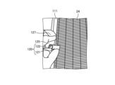
- FIGS. 16 and 17 are diagrams showing an example of how the air filter is removed from the housing body in the air purifier according to Embodiment 1.
- FIG. 16 and 17 are diagrams showing an example of how the air filter is removed from the housing body in the air purifier according to Embodiment 1.
- FIG. 16 and 17 are diagrams showing an example of how the air filter is removed from the housing body in the air purifier according to Embodiment 1.
- FIG. 16 and 17 are diagrams showing an example of how the air filter is removed from the housing body in the air purifier according to Embodiment 1.
- FIG. 16 and 17 the pressing member 121 of the filter fixing portion 120 is rotated from the position on the front side of the air filter 24 onto the support base portion 125 .
- a finger is inserted into the filter finger hooking portion 127 adjacent to the support base portion 125, the finger is put on the side surface of the air filter 24, and pulled forward.
- the air filter 24 is removed from the filter hooking portion 131 on the suction port 13 side of the housing
- a method of using a filter frame when attaching and detaching an air filter in an air purifier is known.
- a filter group including an air filter and a pre-filter arranged on the front side of the air filter is fixed to a filter frame, and projections provided on the filter frame and grooves provided on the housing body , are fitted and slidably guided, the filter is attached together with the filter frame.
- this method requires a separate filter frame, which incurs component costs and mold costs.
- the housing main body 11 facing one side in the width direction of the air filter 24 is provided with the filter fixing portion 120 and the filter finger hooking portion 127, and the other side is facing.
- a wall surface 117x of an inner wall 117 of the housing body 11 is provided with a filter hooking portion 131 formed of a projection. This allows attachment and detachment of the air filter 24 without the need for a filter frame. Since no filter frame is required, the air purifier 1 can be manufactured at a lower cost than the method using a filter frame.
- the air filter 24 can be removed from the housing body 11 .
- the protrusion and the groove are fitted or slid between the air filter 24 and the housing 10. never do. Therefore, when removing the air filter 24, the operation of removing the projection and the groove that are fitted together and the operation of pulling out the air filter 24 while sliding the air filter 24 do not occur. That is, the air filter 24 is not subject to shock or vibration. As a result, the air filter 24 can be attached and detached without dropping or scattering dust or the like. As a result, it is possible to realize the air purifier 1 with easy attachment and detachment of the air filter 24 and good maintainability at low cost.
- the removal work of the air filter 24 can be performed with one hand, the other hand can be used to keep the operator stable, and the operator can work in a stable state. be able to. In this way, since the operator holds the air filter 24 with one hand when performing the attachment/detachment work, even if the operator loses balance, the air filter 24 is held with one hand. is not transmitted to the air filter 24. That is, no stress is generated in the air filter 24 .
- the filter fixing portion 120 and the filter finger hooking portion 127 are provided on the side surface of the air filter 24 opposite to the suction port 13 of the side surface 11c in the X direction.
- the filter fixing portion 120 and the filter fixing portion 120 and the It has a filter finger hook portion 127 . That is, the filter fixing portion 120 and the filter finger hooking portion 127 are provided on the side opposite to the suction port 13 of the housing 10 with the suction port 213a of the blower 21 interposed therebetween.
- the amount of air reaching filter fixing portion 120 and filter finger hooking portion 127 becomes smaller than the amount of air sucked from suction port 213 a of blower 21 , and filter fixing portion 120 and filter finger hooking portion 127 become smaller. is less likely to become dirty with dust. Therefore, the air filter 24 can be attached and detached without getting hands dirty with dust or the like adhering to the filter fixing portion 120 and the filter finger hook portion 127 when attaching and detaching the air filter 24 .
- the air cleaner 1 since the air cleaner 1 is installed on the wall surface 501, the working space on the floor of the person in the room is not occupied as the installation space for the air cleaner 1.
- the space between the suction port 13 of the housing 10 and the side surface of the blower 21 on the side of the suction port 13 is eliminated without arranging the discharge type dust collection device 23 in the depth direction of the blower 21 inside the housing 10. Placed at 42.
- the main body of the air purifier 1 can be made thinner than the conventional one. It does not give a sense of oppression to people in the room. In this way, it is possible to clean the air in the room and to suppress the influence of the existence of the air purifier 1 on the people in the room compared with the past, so that it is possible to provide a comfortable air environment space. become.
- the power cable 51 exposed between the wall surface 501 and the air cleaner 1 can be made inconspicuous, the appearance when the air cleaner 1 is installed on the wall surface 501 of the air cleaner 1 looks good. can do well.
- the power cable 51 is connected to the opening 115 of the rear surface 11a of the housing 10 and the power cable 51 can be guided to the power cable connection terminal block 312, the power cable can be inserted through the opening 115 from the wall surface 501.
- the visibility of the power cable 51 is improved, and the workability of laying the power cable 51 can be improved.
- the terminal block cover 342 covers the power wire connection terminal block 312 and the opening 335 of the power wire insertion portion 311, the air cleaner that prevents the worker or user from touching the power cable 51 at low cost. Machine 1 can be provided.
- the air cleaner 1 since a filter frame is not required for fixing the air filter 24 to the housing body 11, the air cleaner 1 can be provided at a lower cost than when a filter frame is used. can be done. Moreover, by providing the filter fixing portion 120, the filter finger hook portion 127, and the filter hook portion 131, the air filter 24 can be easily attached and detached with one hand without giving shock or vibration to the air filter 24. FIG. Accordingly, it is possible to provide the air cleaner 1 in which the air filter 24 can be attached and detached without dropping or scattering dust or the like.
- 1,100 air purifier 10 housing, 11 housing body, 11a, 341a rear surface, 11b front surface, 11c upper surface, 11d lower surface, 11e, 11f, 341b, 341c, 341d side surface, 12 front panel, 13, 213a suction port , 14 blower outlet, 21 air blower, 22 dust removal filter, 23 discharge type dust collection device, 24 air filter, 31 power wire connection, 32 control circuit, 40 air passage, 41, 42 space, 45 air flow, 51 power supply Cable, 111, 112 Air passage wall, 111a, 111b, 111c, 111d, 111e, 331, 333 Wall portion, 115, 335 Opening, 117 Inner wall, 117x, 501, 502 Wall surface, 120 Filter fixing portion, 121 Pressing member, 122 Fixed member, 125 support base portion, 127 filter finger hook portion, 127a bottom surface, 131 filter hook portion, 211 fan, 212 electric motor, 213 fan casing, 231 positive electrode of discharge portion, 232 negative electrode of discharge portion
Landscapes
- Engineering & Computer Science (AREA)
- Chemical & Material Sciences (AREA)
- Combustion & Propulsion (AREA)
- Mechanical Engineering (AREA)
- General Engineering & Computer Science (AREA)
- Filtering Of Dispersed Particles In Gases (AREA)
Priority Applications (2)
| Application Number | Priority Date | Filing Date | Title |
|---|---|---|---|
| PCT/JP2021/047517 WO2023119472A1 (ja) | 2021-12-22 | 2021-12-22 | 空気清浄機 |
| JP2023568869A JP7630653B2 (ja) | 2021-12-22 | 2021-12-22 | 空気清浄機 |
Applications Claiming Priority (1)
| Application Number | Priority Date | Filing Date | Title |
|---|---|---|---|
| PCT/JP2021/047517 WO2023119472A1 (ja) | 2021-12-22 | 2021-12-22 | 空気清浄機 |
Publications (1)
| Publication Number | Publication Date |
|---|---|
| WO2023119472A1 true WO2023119472A1 (ja) | 2023-06-29 |
Family
ID=86901649
Family Applications (1)
| Application Number | Title | Priority Date | Filing Date |
|---|---|---|---|
| PCT/JP2021/047517 Ceased WO2023119472A1 (ja) | 2021-12-22 | 2021-12-22 | 空気清浄機 |
Country Status (2)
| Country | Link |
|---|---|
| JP (1) | JP7630653B2 (https=) |
| WO (1) | WO2023119472A1 (https=) |
Citations (10)
| Publication number | Priority date | Publication date | Assignee | Title |
|---|---|---|---|---|
| JPS52140482U (https=) * | 1976-04-21 | 1977-10-25 | ||
| JPS6357424U (https=) * | 1986-10-02 | 1988-04-16 | ||
| JPH07190406A (ja) * | 1993-12-24 | 1995-07-28 | Matsushita Electric Ind Co Ltd | 空気調和機の電装品収納ボックス保護カバー |
| JP2005079469A (ja) * | 2003-09-02 | 2005-03-24 | Sharp Corp | 壁掛け構造および壁掛け具 |
| JP2005076906A (ja) * | 2003-08-28 | 2005-03-24 | Sharp Corp | 空気調節装置 |
| JP2007248011A (ja) * | 2006-03-17 | 2007-09-27 | Sharp Corp | 空気調和機 |
| JP2008232554A (ja) * | 2007-03-22 | 2008-10-02 | Matsushita Electric Ind Co Ltd | 空気調和機 |
| JP2010261605A (ja) * | 2009-04-30 | 2010-11-18 | Panasonic Corp | 空気調和機 |
| CN106766035A (zh) * | 2016-12-13 | 2017-05-31 | 广东志高空调有限公司 | 一种挂壁式空调室内机及其全密封电器盒组件 |
| CN212006048U (zh) * | 2020-05-12 | 2020-11-24 | 珠海汉朗环境科技有限公司 | 一种壁挂式臭氧净化机 |
Family Cites Families (1)
| Publication number | Priority date | Publication date | Assignee | Title |
|---|---|---|---|---|
| JP2005076905A (ja) | 2003-08-28 | 2005-03-24 | Sharp Corp | 電気機器および空気調節装置 |
-
2021
- 2021-12-22 WO PCT/JP2021/047517 patent/WO2023119472A1/ja not_active Ceased
- 2021-12-22 JP JP2023568869A patent/JP7630653B2/ja active Active
Patent Citations (10)
| Publication number | Priority date | Publication date | Assignee | Title |
|---|---|---|---|---|
| JPS52140482U (https=) * | 1976-04-21 | 1977-10-25 | ||
| JPS6357424U (https=) * | 1986-10-02 | 1988-04-16 | ||
| JPH07190406A (ja) * | 1993-12-24 | 1995-07-28 | Matsushita Electric Ind Co Ltd | 空気調和機の電装品収納ボックス保護カバー |
| JP2005076906A (ja) * | 2003-08-28 | 2005-03-24 | Sharp Corp | 空気調節装置 |
| JP2005079469A (ja) * | 2003-09-02 | 2005-03-24 | Sharp Corp | 壁掛け構造および壁掛け具 |
| JP2007248011A (ja) * | 2006-03-17 | 2007-09-27 | Sharp Corp | 空気調和機 |
| JP2008232554A (ja) * | 2007-03-22 | 2008-10-02 | Matsushita Electric Ind Co Ltd | 空気調和機 |
| JP2010261605A (ja) * | 2009-04-30 | 2010-11-18 | Panasonic Corp | 空気調和機 |
| CN106766035A (zh) * | 2016-12-13 | 2017-05-31 | 广东志高空调有限公司 | 一种挂壁式空调室内机及其全密封电器盒组件 |
| CN212006048U (zh) * | 2020-05-12 | 2020-11-24 | 珠海汉朗环境科技有限公司 | 一种壁挂式臭氧净化机 |
Also Published As
| Publication number | Publication date |
|---|---|
| JP7630653B2 (ja) | 2025-02-17 |
| JPWO2023119472A1 (https=) | 2023-06-29 |
Similar Documents
| Publication | Publication Date | Title |
|---|---|---|
| CN105371377A (zh) | 空气净化器 | |
| WO2023119471A1 (ja) | 空気清浄機 | |
| JP4728416B2 (ja) | 送風装置 | |
| JP2011102654A (ja) | ダクト型空気調和機 | |
| WO2023119472A1 (ja) | 空気清浄機 | |
| WO2023119473A1 (ja) | 空気清浄機 | |
| WO2009028766A2 (en) | Air conditioner | |
| JP2004218990A (ja) | 空気調和機 | |
| JP5293567B2 (ja) | ダクト型空気調和機 | |
| JP7584674B2 (ja) | 空気清浄機 | |
| JP4221386B2 (ja) | クリーニング機能付き集塵装置および電子機器筐体 | |
| JP7555498B2 (ja) | 空気清浄機および空気清浄機の据付方法 | |
| JP7570531B2 (ja) | 空気清浄機 | |
| JP7573758B2 (ja) | 空気清浄機 | |
| JP7716333B2 (ja) | 空気調和機 | |
| JPS63258615A (ja) | 空気清浄器 | |
| JP7439806B2 (ja) | 送風機 | |
| CN215350951U (zh) | 除臭装置 | |
| WO2023062699A1 (ja) | 空気清浄機 | |
| KR102358647B1 (ko) | 컴퓨터용 데스크탑 케이스 | |
| JP2002136819A (ja) | 空気清浄機 | |
| KR100617627B1 (ko) | 진공 청소기의 피씨비 설치 구조 | |
| KR20040015874A (ko) | 액자형 공기조화기의 디스플레이 패널 개폐구조 | |
| JP5742825B2 (ja) | 空気調和機の表示装置、及び空気調和機 | |
| JP2000249362A (ja) | ビルトイン型空気調和機 |
Legal Events
| Date | Code | Title | Description |
|---|---|---|---|
| 121 | Ep: the epo has been informed by wipo that ep was designated in this application |
Ref document number: 21968909 Country of ref document: EP Kind code of ref document: A1 |
|
| WWE | Wipo information: entry into national phase |
Ref document number: 2023568869 Country of ref document: JP |
|
| NENP | Non-entry into the national phase |
Ref country code: DE |
|
| 122 | Ep: pct application non-entry in european phase |
Ref document number: 21968909 Country of ref document: EP Kind code of ref document: A1 |