WO2023112784A1 - 動画像復号装置、ポスト画像処理装置、動画像符号化装置、動画像復号方法及び動画像符号化方法 - Google Patents
動画像復号装置、ポスト画像処理装置、動画像符号化装置、動画像復号方法及び動画像符号化方法 Download PDFInfo
- Publication number
- WO2023112784A1 WO2023112784A1 PCT/JP2022/045001 JP2022045001W WO2023112784A1 WO 2023112784 A1 WO2023112784 A1 WO 2023112784A1 JP 2022045001 W JP2022045001 W JP 2022045001W WO 2023112784 A1 WO2023112784 A1 WO 2023112784A1
- Authority
- WO
- WIPO (PCT)
- Prior art keywords
- image
- auxiliary information
- decoding
- recognition
- encoding
- Prior art date
- Legal status (The legal status is an assumption and is not a legal conclusion. Google has not performed a legal analysis and makes no representation as to the accuracy of the status listed.)
- Ceased
Links
Images





Classifications
-
- H—ELECTRICITY
- H04—ELECTRIC COMMUNICATION TECHNIQUE
- H04N—PICTORIAL COMMUNICATION, e.g. TELEVISION
- H04N19/00—Methods or arrangements for coding, decoding, compressing or decompressing digital video signals
- H04N19/70—Methods or arrangements for coding, decoding, compressing or decompressing digital video signals characterised by syntax aspects related to video coding, e.g. related to compression standards
-
- H—ELECTRICITY
- H04—ELECTRIC COMMUNICATION TECHNIQUE
- H04N—PICTORIAL COMMUNICATION, e.g. TELEVISION
- H04N19/00—Methods or arrangements for coding, decoding, compressing or decompressing digital video signals
- H04N19/10—Methods or arrangements for coding, decoding, compressing or decompressing digital video signals using adaptive coding
- H04N19/169—Methods or arrangements for coding, decoding, compressing or decompressing digital video signals using adaptive coding characterised by the coding unit, i.e. the structural portion or semantic portion of the video signal being the object or the subject of the adaptive coding
- H04N19/17—Methods or arrangements for coding, decoding, compressing or decompressing digital video signals using adaptive coding characterised by the coding unit, i.e. the structural portion or semantic portion of the video signal being the object or the subject of the adaptive coding the unit being an image region, e.g. an object
-
- H—ELECTRICITY
- H04—ELECTRIC COMMUNICATION TECHNIQUE
- H04N—PICTORIAL COMMUNICATION, e.g. TELEVISION
- H04N19/00—Methods or arrangements for coding, decoding, compressing or decompressing digital video signals
- H04N19/20—Methods or arrangements for coding, decoding, compressing or decompressing digital video signals using video object coding
-
- H—ELECTRICITY
- H04—ELECTRIC COMMUNICATION TECHNIQUE
- H04N—PICTORIAL COMMUNICATION, e.g. TELEVISION
- H04N19/00—Methods or arrangements for coding, decoding, compressing or decompressing digital video signals
- H04N19/44—Decoders specially adapted therefor, e.g. video decoders which are asymmetric with respect to the encoder
-
- H—ELECTRICITY
- H04—ELECTRIC COMMUNICATION TECHNIQUE
- H04N—PICTORIAL COMMUNICATION, e.g. TELEVISION
- H04N19/00—Methods or arrangements for coding, decoding, compressing or decompressing digital video signals
- H04N19/46—Embedding additional information in the video signal during the compression process
-
- H—ELECTRICITY
- H04—ELECTRIC COMMUNICATION TECHNIQUE
- H04N—PICTORIAL COMMUNICATION, e.g. TELEVISION
- H04N19/00—Methods or arrangements for coding, decoding, compressing or decompressing digital video signals
- H04N19/60—Methods or arrangements for coding, decoding, compressing or decompressing digital video signals using transform coding
- H04N19/61—Methods or arrangements for coding, decoding, compressing or decompressing digital video signals using transform coding in combination with predictive coding
-
- H—ELECTRICITY
- H04—ELECTRIC COMMUNICATION TECHNIQUE
- H04N—PICTORIAL COMMUNICATION, e.g. TELEVISION
- H04N19/00—Methods or arrangements for coding, decoding, compressing or decompressing digital video signals
- H04N19/85—Methods or arrangements for coding, decoding, compressing or decompressing digital video signals using pre-processing or post-processing specially adapted for video compression
Definitions
- Embodiments of the present invention relate to a video decoding device, a post-image processing device, a video encoding device, a video decoding method, a video encoding method, and the like.
- This application claims priority based on Japanese Patent Application No. 2021-202161 filed in Japan on December 14, 2021, the content of which is incorporated herein.
- a moving image encoding device that generates encoded data by encoding a moving image and a moving image that generates a decoded image by decoding the encoded data in order to efficiently transmit or record the moving image An image decoding device is used.
- Specific video encoding methods include H.264/AVC and H.265/HEVC (High-Efficiency Video Coding).
- the images (pictures) that make up the video are divided into slices obtained by dividing an image, and coding tree units (CTU: Coding Tree Units) obtained by dividing a slice. ), a coding unit obtained by dividing the coding tree unit (Coding Unit: CU)), and a transform unit obtained by dividing the coding unit (TU: Transform Unit), and encoded/decoded for each CU.
- CTU Coding Tree Units
- a predicted image is normally generated based on a locally decoded image obtained by encoding/decoding an input image, and the predicted image is generated from the input image (original image).
- the prediction error obtained by subtraction (sometimes called the "difference image” or “residual image”) is encoded.
- Inter-prediction and intra-prediction are methods for generating predicted images.
- Non-Patent Document 1 can be cited as a technique for video encoding and decoding in recent years.
- Non-Patent Document 1 is a moving image encoding/decoding method with very high encoding efficiency.
- Non-Patent Document 2 discusses a method of integrating the description of the analysis result of a moving image and the coding of the moving image.
- Non-Patent Document 1 is a moving image encoding and decoding method with high encoding efficiency, when image recognition is performed on the decoded moving image, if the transmission rate is low, the image recognition accuracy will be reduced due to encoding distortion. is reduced.
- Non-Patent Document 2 discloses a method of integrating the description of video analysis results and video encoding, but the problem is that the encoding efficiency is not sufficient and a low transmission bit rate cannot be achieved.
- a moving image decoding device is an image decoding device that decodes an image from encoded data, and includes auxiliary information indicating at least one of the position, size, and type of a recognition target of the decoded image. It is characterized by comprising at least an auxiliary information decoding unit for decoding.
- a post-image processing apparatus uses network parameters decoded from an auxiliary information decoding unit that decodes auxiliary information indicating at least one of the position, size, and type of an image to be recognized, to perform post processing. It is characterized by performing image processing.
- a video encoding device is an image encoding device that encodes an input image, and includes auxiliary information indicating at least one of the position, size, and type of a recognition target of the input image. It is characterized by comprising at least an auxiliary information encoding unit for encoding.
- a moving image decoding method is an image decoding method for decoding an image from encoded data, wherein auxiliary information indicating at least one of the position, size, and type of a recognition target of the decoded image is provided. It is characterized by including at least a step of decoding.
- a video encoding method is an image encoding method for encoding an input image, wherein auxiliary information indicating at least one of the position, size, and type of a recognition target of the input image is provided. It is characterized by including at least the step of encoding.
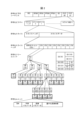
- FIG. 4 is a diagram showing a hierarchical structure of encoded data
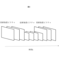
- 4 is a conceptual diagram of an image to be processed in the moving image transmission system according to the embodiment
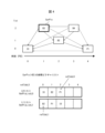
- FIG. FIG. 2 is a conceptual diagram showing an example of reference pictures and reference picture lists
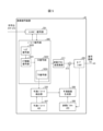
- 1 is a schematic diagram showing the configuration of an image decoding device
- FIG. 4 is a flowchart for explaining schematic operations of the image decoding device
- It is a block diagram which shows the structure of an image coding apparatus.
- FIG. 4 is a diagram showing a configuration example of an SEI syntax table of image recognition auxiliary information that defines auxiliary information according to an embodiment
- FIG. 3 is a schematic diagram showing the configuration of another moving image transmission system according to this embodiment
- FIG. 4 is a diagram showing a configuration example of an SEI syntax table of network parameters that define auxiliary information according to an embodiment
- FIG. 4 is a diagram showing a configuration example of an APS syntax table that defines image recognition auxiliary information according to an embodiment
- FIG. 4 is a diagram showing a configuration example of an APS syntax table that defines image recognition auxiliary information according to an embodiment
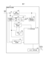
- FIG. 1 is a schematic diagram showing the configuration of a moving image transmission system according to this embodiment.
- the moving image transmission system 1 is a system that transmits encoded data obtained by encoding an image, decodes and displays the transmitted encoded data, and performs image recognition.
- a moving image transmission system 1 includes a moving image encoding device 10, a network 21, a moving image decoding device 30, an image display device 41, and an image recognition device 51.
- FIG. 1 is a system that transmits encoded data obtained by encoding an image, decodes and displays the transmitted encoded data, and performs image recognition.
- a moving image transmission system 1 includes a moving image encoding device 10, a network 21, a moving image decoding device 30, an image display device 41, and an image recognition device 51.
- the video encoding device 10 includes an image encoding device (image encoding unit) 11, an image analysis device (image analysis unit) 61, an auxiliary information creation device (auxiliary information creation unit) 71, an auxiliary information encoding device (auxiliary information encoder) 81.
- the video decoding device 30 is composed of an image decoding device (image decoding section) 31 and an auxiliary information decoding device (auxiliary information decoding section) 91 .
- the image encoding device 11 compresses and encodes the input moving image T.
- the image analysis device 61 analyzes the input moving image T, analyzes information about which region in the picture should be used in the image recognition device 51, and sends the analysis result to the auxiliary information creation device 71.
- the auxiliary information creation device 71 Based on the analysis result of the image analysis device 61, the auxiliary information creation device 71 provides information as to whether or not the image recognition device should be operated for the picture, and which region in the picture the image recognition device should be operated. This auxiliary information is generated and sent to the auxiliary information encoding device 81 .
- the auxiliary information encoding device 81 encodes the auxiliary information created by the auxiliary information creating device 71 according to a predetermined syntax.
- the output of the image encoding device 11 and the output of the auxiliary information encoding device 81 are sent to the network 21 as encoded data Te.
- the moving image encoding device 10 receives an input image T as an input, compresses and encodes the image, analyzes the image, generates auxiliary information to be input to the image recognition device 51, encodes it, and encodes it. Transformation data Te is generated and sent to the network 21 .
- auxiliary information coding device 81 is not connected to the image coding device 11 in FIG. 1, the auxiliary information coding device 81 and the image coding device 11 may communicate necessary information as appropriate.
- the network 21 transmits the encoded auxiliary information and encoded data Te to the image decoding device 31. Part or all of the coded auxiliary information may be included in the coded data Te as auxiliary extension information SEI.
- the network 21 is the Internet, a Wide Area Network (WAN), a Local Area Network (LAN), or a combination thereof.
- the network 21 is not necessarily a two-way communication network, and may be a one-way communication network that transmits broadcast waves such as terrestrial digital broadcasting and satellite broadcasting. Also, the network 21 may be replaced by a storage medium recording encoded data Te such as a DVD (Digital Versatile Disc: registered trademark) or a BD (Blu-ray Disc: registered trademark).
- the video decoding device 30 receives the encoded data Te sent from the network 21, decodes the video Td, and sends it to the image display device 41 and the image recognition device 51. Also, the auxiliary information is decoded and output to the image recognition device 51 .
- the image decoding device 31 decodes each piece of encoded data Te transmitted by the network 21, generates a decoded moving image Td, and supplies it to the image display device 41 and the image recognition device 51.
- the auxiliary information decoding device 91 decodes the coded auxiliary information transmitted by the network 21 to generate auxiliary information and sends it to the image recognition device 51 .
- the auxiliary information decoding device 91 may be included in the image decoding device 31.
- the auxiliary information decoding device 91 may be included in the image decoding device 31 separately from each functional unit of the image decoding device 31.
- FIG. although not connected to the image decoding device 31 in FIG. 1, the auxiliary information decoding device 91 and the image decoding device 31 may appropriately communicate necessary information.
- the image display device 41 displays all or part of the decoded moving image Td input from the image decoding device 31.
- the image display device 41 includes a display device such as a liquid crystal display or an organic EL (Electro-luminescence) display.
- the form of the display includes stationary, mobile, HMD, and the like.
- the image decoding device 31 has high processing power, it displays an image with high image quality, and when it has only lower processing power, it displays an image that does not require high processing power and display power.
- the image recognition device 51 uses the decoded moving image Td decoded by the image decoding device 31 and the auxiliary information decoded by the auxiliary information decoding device 91 to perform object detection of the image, object region division, object tracking, and motion detection. Recognition, human motion evaluation, etc.
- x ? y : z is a ternary operator that takes y if x is true (other than 0) and z if x is false (0).
- abs(a) is a function that returns the absolute value of a.
- Int(a) is a function that returns the integer value of a.
- floor(a) is a function that returns the largest integer less than or equal to a.
- ceil(a) is a function that returns the smallest integer greater than or equal to a.
- a/d represents the division of a by d (truncated after the decimal point).
- FIG. 2 is a diagram showing the hierarchical structure of data in the encoded data Te.
- the encoded data Te illustratively includes a sequence and a plurality of pictures that constitute the sequence.
- FIG. 2 shows a coded video sequence defining a sequence SEQ, a coded picture defining a picture PICT, a coded slice defining a slice S, a coded slice data defining a slice data, and a coded slice data included in the coded slice data.
- a diagram showing a coding tree unit and coding units included in the coding tree unit is shown.
- the encoded video sequence defines a set of data that the image decoding device 31 refers to in order to decode the sequence SEQ to be processed.
- Sequence SEQ as shown in Figure 2, consists of video parameter set VPS (Video Parameter Set), sequence parameter set SPS (Sequence Parameter Set), picture parameter set PPS (Picture Parameter Set), adaptation parameter set (APS), picture PICT , and Supplemental Enhancement Information (SEI).
- VPS Video Parameter Set
- sequence parameter set SPS Sequence Parameter Set
- picture parameter set PPS Picture Parameter Set
- APS adaptation parameter set
- SEI Supplemental Enhancement Information
- a video parameter set VPS is a set of coding parameters common to multiple video images, a set of coding parameters common to multiple video images, and a set of coding parameters related to multiple layers and individual layers included in a video image. Sets are defined.
- the sequence parameter set SPS defines a set of encoding parameters that the image decoding device 31 refers to in order to decode the target sequence. For example, the width and height of the picture are defined. A plurality of SPSs may exist. In that case, one of a plurality of SPSs is selected from the PPS.
- sequence parameter set SPS contains the following syntax elements.
- pic_width_max_in_luma_samples is a syntax element that specifies the width of the largest image among the images in a single sequence, in luminance block units. Also, the value of the syntax element is required not to be 0 and to be an integer multiple of Max(8, MinCbSizeY). Here, MinCbSizeY is a value determined by the minimum size of the luminance block.
- pic_height_max_in_luma_samples is a syntax element that specifies the height of the image with the maximum height among the images in a single sequence, in luminance block units. Also, the value of the syntax element is required not to be 0 and to be an integer multiple of Max(8, MinCbSizeY).
- the picture parameter set PPS defines a set of coding parameters that the image decoding device 31 refers to in order to decode each picture in the target sequence.
- a plurality of PPSs may exist. In that case, one of a plurality of PPSs is selected from each picture in the target sequence.
- the picture parameter set PPS contains the following syntax elements.
- pic_width_in_luma_samples is a syntax element that specifies the width of the target picture.
- the value of this syntax element is required to be not 0, but an integral multiple of Max(8, MinCbSizeY) and less than or equal to pic_width_max_in_luma_samples.
- pic_height_in_luma_samples is a syntax element that specifies the height of the target picture.
- the value of the syntax element is required to be not 0, but an integer multiple of Max(8, MinCbSizeY) and less than or equal to pic_height_max_in_luma_samples.
- FIG. 3 is a conceptual diagram of an image to be processed in the moving image transmission system 1, showing changes in resolution of the image over time. However, in FIG. 3, it is not distinguished whether the image is encoded or not.
- FIG. 3 shows an example of transmitting an image to the image decoding device 31 while adaptively changing the resolution using the picture parameter set PPS in the process of the moving image transmission system 1.
- the encoded picture defines a set of data that the image decoding device 31 refers to in order to decode the picture PICT to be processed.
- a picture PICT includes a picture header PH, slice 0 to slice NS-1 (NS is the total number of slices included in the picture PICT), as shown in FIG.
- the coded slice defines a set of data that the image decoding device 31 refers to in order to decode the slice S to be processed.
- a slice includes a slice header and slice data, as shown in FIG.
- the slice header contains a group of coding parameters that the image decoding device 31 refers to in order to determine the decoding method for the target slice.
- Slice type designation information (slice_type) that designates a slice type is an example of a coding parameter included in a slice header.
- Slice types that can be specified by the slice type specifying information include (1) an I slice that uses only intra prediction during encoding, (2) simple prediction (L0 prediction) or intra prediction that uses during encoding. (3) B slices using uni-prediction (L0 prediction or L1 prediction), bi-prediction, or intra-prediction in encoding.
- inter prediction is not limited to uni-prediction and bi-prediction, and a predicted image may be generated using more reference pictures.
- P and B slices they refer to slices containing blocks for which inter prediction can be used.
- the slice header may contain a reference (pic_parameter_set_id) to the picture parameter set PPS.
- the encoded slice data defines a set of data that the image decoding device 31 refers to in order to decode slice data to be processed.
- the slice data contains CTU, as shown in the encoded slice header in FIG.
- a CTU is a block of a fixed size (for example, 64x64) that forms a slice, and is also called a maximum coding unit (LCU).
- FIG. 2 defines a set of data that the image decoding device 31 refers to in order to decode the CTU to be processed.
- CTU uses recursive quad tree partitioning (QT (Quad Tree) partitioning), binary tree partitioning (BT (Binary Tree) partitioning), or ternary tree partitioning (TT (Ternary Tree) partitioning) to perform coding processing. It is divided into coding units CU, which are basic units. BT partitioning and TT partitioning are collectively called multi-tree partitioning (MT (Multi Tree) partitioning).
- MT Multi Tree partitioning
- a node of a tree structure obtained by recursive quadtree partitioning is called a coding node.
- Intermediate nodes of quadtrees, binary trees, and ternary trees are coding nodes, and the CTU itself is defined as a top-level coding node.
- FIG. 2 defines a set of data that the image decoding device 31 refers to in order to decode the encoding unit to be processed.
- a CU is composed of a CU header CUH, prediction parameters, transform parameters, quantized transform coefficients, and the like.
- a prediction mode and the like are defined in the CU header.
- Prediction processing may be performed in units of CUs or in units of sub-CUs, which are subdivided into CUs. If the CU and sub-CU sizes are equal, there is one sub-CU in the CU. If the CU is larger than the sub-CU size, the CU is split into sub-CUs. For example, if the CU is 8x8 and the sub-CU is 4x4, the CU is divided into 4 sub-CUs consisting of 2 horizontal divisions and 2 vertical divisions.
- Intra prediction is prediction within the same picture
- inter prediction is prediction processing performed between different pictures (for example, between display times, between layer images).
- the transform/quantization process is performed in CU units, but the quantized transform coefficients may be entropy coded in subblock units such as 4x4.
- prediction parameter A predicted image is derived from the prediction parameters associated with the block.
- the prediction parameters include prediction parameters for intra prediction and inter prediction.
- the prediction parameters for inter prediction are described below.
- the inter prediction parameters are composed of prediction list usage flags predFlagL0 and predFlagL1, reference picture indices refIdxL0 and refIdxL1, and motion vectors mvL0 and mvL1.
- predFlagL0 and predFlagL1 are flags indicating whether or not reference picture lists (L0 list, L1 list) are used, and when the value is 1, the corresponding reference picture list is used.
- flag when the term "flag indicating whether or not it is XX" is used, when the flag is other than 0 (for example, 1), it is XX, and 0 is not XX. Treat 1 as true and 0 as false (same below).
- other values can be used as true and false values.
- FIG. 4 is a conceptual diagram showing an example of reference pictures and reference picture lists.
- rectangles are pictures, arrows are picture reference relationships, the horizontal axis is time, I, P, and B in the rectangle are intra pictures, uni-predictive pictures, bi-predictive pictures, respectively.
- the numbers in the rectangles indicate the decoding order.
- the decoding order of the pictures is I0, P1, B2, B3, B4, and the display order is I0, B3, B2, B4, P1.
- FIG. 4 shows an example of a reference picture list for picture B3 (current picture).
- a reference picture list is a list representing reference picture candidates, and one picture (slice) may have one or more reference picture lists.
- the target picture B3 has two reference picture lists, an L0 list RefPicList0 and an L1 list RefPicList1.
- LX is a description method used when L0 prediction and L1 prediction are not distinguished, and hereinafter, parameters for the L0 list and parameters for the L1 list are distinguished by replacing LX with L0 and L1.
- the image decoding device 31 includes an entropy decoding unit 301, a parameter decoding unit (prediction image decoding device) 302, a loop filter 305, a reference picture memory 306, a prediction parameter memory 307, a prediction image generation unit (prediction image generation device) 308, an inverse quantum It includes a normalization/inverse transformation unit 311 , an addition unit 312 , and a prediction parameter derivation unit 320 .
- the image decoding device 31 may have a configuration in which the loop filter 305 is not included in accordance with the image encoding device 11 described later.
- the parameter decoding unit 302 further includes a header decoding unit 3020, a CT information decoding unit 3021, and a CU decoding unit 3022 (prediction mode decoding unit), and the CU decoding unit 3022 further includes a TU decoding unit 3024. These may be collectively called a decoding module.
- Header decoding section 3020 decodes parameter set information such as VPS, SPS, PPS, and APS, and slice headers (slice information) from encoded data.
- CT information decoding section 3021 decodes CT from encoded data.
- a CU decoding unit 3022 decodes a CU from encoded data.
- TU decoding section 3024 decodes QP update information (quantization correction value) and quantization prediction error (residual_coding) from encoded data when prediction error is included in TU.
- CTU and CU as processing units
- processing may be performed in sub-CU units.
- CTU and CU may be read as blocks
- sub-CU may be read as sub-blocks
- processing may be performed in units of blocks or sub-blocks.
- the entropy decoding unit 301 performs entropy decoding on the encoded data Te input from the outside to decode individual codes (syntax elements).
- syntax elements For entropy coding, a method of variable-length coding syntax elements using a context (probability model) adaptively selected according to the type of syntax elements and surrounding circumstances, a predetermined table, or There is a method of variable-length coding syntax elements using a formula.
- the former CABAC Context Adaptive Binary Arithmetic Coding
- stores the context CABAC state predominant symbol type (0 or 1) and probability state index pStateIdx specifying probability
- the entropy decoding unit 301 initializes all CABAC states at the beginning of a segment (tile, CTU row, slice).
- the entropy decoding unit 301 converts the syntax element into a binary string (Bin String) and decodes each bit of the Bin String. If the context is used, derive the context index ctxInc for each bit of the syntax element, decode the bit using the context, and update the CABAC state of the used context. Bits without context are decoded with equal probability (EP, bypass) and the ctxInc derivation and CABAC state are omitted.
- the decoded syntax elements include prediction information for generating a predicted image and prediction error for generating a difference image.
- the entropy decoding unit 301 outputs the decoded code to the parameter decoding unit 302. Control of which code is to be decoded is performed based on an instruction from parameter decoding section 302 .
- FIG. 6 is a flowchart for explaining a schematic operation of the image decoding device 31. As shown in FIG.
- the header decoding unit 3020 decodes parameter set information such as VPS, SPS, and PPS from the encoded data.
- the header decoding unit 3020 decodes the slice header (slice information) from the encoded data.
- the image decoding device 31 derives a decoded image of each CTU by repeating the processing from S1300 to S5000 for each CTU included in the target picture.
- the CT information decoding unit 3021 decodes the CTU from the encoded data.
- the CT information decoding unit 3021 decodes the CT from the encoded data.
- the CU decoding unit 3022 performs S1510 and S1520 to decode the CU from the encoded data.
- the CU decoding unit 3022 decodes CU information, prediction information, TU split flag split_transform_flag, CU residual flags cbf_cb, cbf_cr, cbf_luma, etc. from the encoded data.
- TU decoding section 3024 decodes QP update information and quantization prediction error from encoded data when prediction error is included in TU.
- the QP update information is a difference value from the quantization parameter prediction value qPpred, which is the prediction value of the quantization parameter QP.
- the predicted image generation unit 308 generates a predicted image based on the prediction information for each block included in the target CU.
- the inverse quantization/inverse transform unit 311 executes inverse quantization/inverse transform processing for each TU included in the target CU.
- the addition unit 312 adds the predicted image supplied from the predicted image generation unit 308 and the prediction error supplied from the inverse quantization/inverse transform unit 311, thereby decoding the target CU. Generate an image.
- the loop filter 305 generates a decoded image by applying loop filters such as deblocking filter, SAO, and ALF to the decoded image.
- loop filters such as deblocking filter, SAO, and ALF
- the prediction parameter deriving unit 320 derives inter prediction parameters by referring to the prediction parameters stored in the prediction parameter memory 307 based on the syntax elements input from the parameter decoding unit 302. Also, the prediction parameters are output to the prediction image generation unit 308 and the prediction parameter memory 307 .
- a loop filter 305 is a filter provided in the encoding loop, and is a filter that removes block distortion and ringing distortion and improves image quality.
- a loop filter 305 applies filters such as a deblocking filter, a sample adaptive offset (SAO), and an adaptive loop filter (ALF) to the decoded image of the CU generated by the addition unit 312 .
- filters such as a deblocking filter, a sample adaptive offset (SAO), and an adaptive loop filter (ALF) to the decoded image of the CU generated by the addition unit 312 .
- the reference picture memory 306 stores the decoded image of the CU in a predetermined position for each target picture and target CU.
- the prediction parameter memory 307 stores prediction parameters in predetermined positions for each CTU or CU. Specifically, the prediction parameter memory 307 stores the parameters decoded by the parameter decoding unit 302, the parameters derived by the prediction parameter deriving unit 320, and the like.
- the parameters derived by the prediction parameter derivation unit 320 are input to the prediction image generation unit 308 .
- the predicted image generation unit 308 reads a reference picture from the reference picture memory 306 .
- a predicted image generation unit 308 generates a predicted image of a block or sub-block using parameters and a reference picture (reference picture block) in a prediction mode indicated by predMode.
- a reference picture block is a set of pixels on a reference picture (usually rectangular and therefore called a block), and is an area referred to for generating a prediction image.
- the inverse quantization/inverse transform unit 311 inversely quantizes the quantized transform coefficients input from the parameter decoding unit 302 to obtain transform coefficients.
- the addition unit 312 adds the predicted image of the block input from the predicted image generation unit 308 and the prediction error input from the inverse quantization/inverse transform unit 311 for each pixel to generate a decoded image of the block.
- the adder 312 stores the decoded image of the block in the reference picture memory 306 and also outputs it to the loop filter 305 .
- the inverse quantization/inverse transform unit 311 inversely quantizes the quantized transform coefficients input from the parameter decoding unit 302 to obtain transform coefficients.
- the addition unit 312 adds the predicted image of the block input from the predicted image generation unit 308 and the prediction error input from the inverse quantization/inverse transform unit 311 for each pixel to generate a decoded image of the block.
- the adder 312 stores the decoded image of the block in the reference picture memory 306 and also outputs it to the loop filter 305 .
- FIG. 7 is a block diagram showing the configuration of the image encoding device 11 according to this embodiment.
- the image coding device 11 includes a predicted image generation unit 101, a subtraction unit 102, a transform/quantization unit 103, an inverse quantization/inverse transform unit 105, an addition unit 106, a loop filter 107, a prediction parameter memory (prediction parameter storage unit, frame memory) 108, reference picture memory (reference image storage unit, frame memory) 109, coding parameter determination unit 110, parameter coding unit 111, prediction parameter derivation unit 120, and entropy coding unit 104.
- the predicted image generation unit 101 generates a predicted image for each CU.
- the subtraction unit 102 subtracts the pixel values of the predicted image of the block input from the predicted image generation unit 101 from the pixel values of the image T to generate prediction errors.
- Subtraction section 102 outputs the prediction error to transform/quantization section 103 .
- the transform/quantization unit 103 calculates transform coefficients by frequency transforming the prediction error input from the subtraction unit 102, and derives quantized transform coefficients by quantization.
- the transform/quantization unit 103 outputs the quantized transform coefficients to the parameter coding unit 111 and the inverse quantization/inverse transform unit 105 .
- the inverse quantization/inverse transform unit 105 is the same as the inverse quantization/inverse transform unit 311 (FIG. 5) in the image decoding device 31, and description thereof is omitted.
- the calculated prediction error is output to addition section 106 .
- a parameter encoding unit 111 performs encoding processing of parameters such as header information, division information, prediction information, and quantized transform coefficients.
- the entropy coding unit 104 receives input from the parameter coding unit 111 of the quantized transform coefficients and coding parameters (division information, prediction parameters). The entropy encoding unit 104 entropy-encodes these to generate and output encoded data Te.
- the prediction parameter derivation unit 120 derives prediction parameters from the parameters input from the coding parameter determination unit 110.
- the derived prediction parameters are output to parameter coding section 111 .
- the addition unit 106 adds pixel values of the prediction block input from the prediction image generation unit 101 and prediction errors input from the inverse quantization/inverse transformation unit 105 for each pixel to generate a decoded image.
- the addition unit 106 stores the generated decoded image in the reference picture memory 109 .
- a loop filter 107 applies a deblocking filter, SAO, and ALF to the decoded image generated by the addition unit 106.
- the loop filter 107 does not necessarily include the three types of filters described above, and may be configured with only a deblocking filter, for example.
- the prediction parameter memory 108 stores the prediction parameters generated by the coding parameter determination unit 110 in predetermined positions for each current picture and CU.
- the reference picture memory 109 stores the decoded image generated by the loop filter 107 in a predetermined position for each target picture and CU.
- the coding parameter determination unit 110 selects one set from a plurality of sets of coding parameters.
- the coding parameter is the above-described QT, BT or TT division information, prediction parameters, or parameters to be coded generated in relation to these.
- the predicted image generator 101 uses these coding parameters to generate predicted images.
- the coding parameter determination unit 110 calculates an RD cost value indicating the magnitude of the information amount and the coding error for each of the multiple sets.
- the RD cost value is, for example, the sum of the code amount and the value obtained by multiplying the squared error by the coefficient ⁇ .
- the code amount is the information amount of the encoded data Te obtained by entropy-encoding the quantization error and the encoding parameter.
- the squared error is the sum of squares of the prediction errors calculated in subtraction section 102 .
- the coefficient ⁇ is a preset real number greater than zero. Coding parameter determination section 110 selects a set of coding parameters that minimizes the calculated cost value. Coding parameter determination section 110 outputs the determined coding parameters to parameter coding section 111 and prediction parameter derivation section 120 .
- Non-Patent Document 1 is a video encoding/decoding method with very high encoding efficiency. There is a problem that the image recognition accuracy is reduced.
- Non-Patent Document 2 discusses a method of integrating the description of video analysis results and video encoding, but the problem is that the encoding efficiency is not sufficient and a low transmission bit rate cannot be achieved. was there.
- the image recognition accuracy can be maintained even at a low rate by encoding and decoding additional auxiliary information without significantly changing the framework of video encoding and decoding methods. provide a framework.
- FIG. 8 is a diagram showing one form of syntax of side information encoded and decoded by the side information encoding device 81 and the side information decoding device 91 of this embodiment.
- This example shows an SEI called image_recognition_hint_sei_message.
- This SEI aims at improving the recognition accuracy and reducing the amount of processing when the image recognition apparatus processes the picture. Therefore, it is an SEI message that encodes and decodes at least one of the recognition target type, position, and size for the picture as auxiliary information, and has the number of bytes of the value of payloadSize.
- image_recognition_idc is an index value that indicates the type of image recognition processing. If the value of image_recognition_idc is 0, it is assumed that there is no recognition target in the picture, and no recognition area information is described. In this example, if the value of image_recognition_idc is 1, describe the recognition target information. Note that image_recognition_idc may add a syntax element of auxiliary information according to the type of image recognition processing.
- number_of_region_minus1 is a syntax element that represents the number of recognition regions minus one. Describe the type, position, and size information of the recognition target for the number of values of number_of_region_minus1 plus 1.
- region_id is an index value that represents the type of recognition target. Allocation of index values is determined according to recognition targets in the image recognition device 51 . For example, when the image recognition device 51 detects a person, if the value of region_id is 0, the recognition target is a person, and if the value of region_id is 1, it indicates other than that. For example, when the image recognition device 51 recognizes a person, a bicycle, and a car, if the region_id value is 0, the recognition target is a person, if the region_id value is 1, the recognition target is a bicycle, and if the region_id value is 3. If so, the recognition target is a car, and if the value of region_id is 4, the recognition target is something else.
- region_x and region_y are syntax elements that indicate the position of the recognition target.
- region_x is the x coordinate value (horizontal direction) of the upper left luminance of the rectangular region.
- region_y is the y coordinate value (vertical direction) of the upper left luminance of the rectangular region.
- region_x and region_y may be relative positions within the screen. For example, it may be a position within the screen when the screen size is normalized to a predetermined fixed size (eg, 512 ⁇ 512).
- region_width and region_hight are syntax elements that indicate the size of recognition correspondence.
- region_width is the number of pixels of luminance in the horizontal direction of the rectangular region. Note that the value of region_x+region_width shall not exceed the number of pixels in the horizontal direction of the picture.
- region_hight is the number of pixels of luminance in the vertical direction of the rectangular region. Note that the value of region_y+region_height shall not exceed the number of pixels in the vertical direction of the picture.
- the recognition target area is a rectangle, and a method of representing the upper left coordinate value of the rectangle and the number of pixels in the horizontal and vertical directions is shown, but another method may be used for the recognition target area.
- the position information (region_x, region_y) of the recognition target may be the upper right, lower left, lower right, or center of gravity instead of the upper left of the rectangular area.
- the size of the region (region_width, region_height) may be limited to a square other than a rectangle, and only the number of pixels on one side (region_size) may be specified.
- the position and size may be specified in 4x4 units, 16x16 units, or CTU addresses and the number of CTUs, which are encoding units, instead of pixel units.
- rbsp_trailing_bits() adds 1 to 8 bits of data so that the number of SEI bits is in bytes, and the number of SEI bytes matches the value of payloadSize.
- the image analysis device 61 analyzes the input moving image T and detects recognition target candidates.
- accuracy in order to suppress the amount of processing, it is assumed that accuracy as a recognition target candidate is sufficient.
- the recognition candidate area may be set in advance by the image analysis device 61 if the position in the picture to be recognized can be assumed, for example, like a fixed camera image.
- the auxiliary information creating device 71 converts the rectangular area information of the candidate for recognition detected by the image analyzing device 61 into information on the position in the picture and the size of the rectangle, and sends it to the auxiliary information encoding device 81 .
- the output of the auxiliary information creating device 71 may be input to the image encoding device 11.
- the image encoding device 11 may control the image quality of the area portion of the recognition target candidate created by the auxiliary information creating section 71.
- high image quality may be achieved by using a quantization parameter with a smaller value than other areas in the picture. By doing this, it is possible to improve recognition accuracy.
- the image recognition device 51 receives, as auxiliary information, information on the type, position, and size of the object to be recognized in the picture.
- the amount of processing can be greatly reduced because only the pixels in the recognition target candidate area need to be processed without using all the information in the picture.
- the types of recognition target candidates can be limited in advance, it is possible to improve the recognition accuracy. Further, if the image quality of the decoded image of the recognition target area is improved, the recognition accuracy is improved.
- the present embodiment even if a decoded image encoded at a low rate is used, it is possible to improve the image recognition accuracy of the image recognition device 51 and reduce the amount of image recognition processing.
- FIG. 9 is a schematic diagram showing the configuration of another moving image transmission system according to this embodiment.
- the moving image transmission system 1 is a system that transmits encoded data obtained by encoding an image, decodes and displays the transmitted encoded data, and performs image recognition.
- a moving image transmission system 1 includes a moving image encoding device 10, a network 21, a moving image decoding device 30, an image display device 41, and an image recognition device 51.
- FIG. 1 is a system that transmits encoded data obtained by encoding an image, decodes and displays the transmitted encoded data, and performs image recognition.
- a moving image transmission system 1 includes a moving image encoding device 10, a network 21, a moving image decoding device 30, an image display device 41, and an image recognition device 51.
- the video encoding device 10 includes an image encoding device (image encoding unit) 11, an image analysis device (image analysis unit) 61, an auxiliary information creation device (auxiliary information creation unit) 71, an auxiliary information encoding device (auxiliary information 81 and a pre-image processing device (pre-image processing unit) 1001 .
- the video decoding device 30 is composed of an image decoding device (image decoding section) 31 , an auxiliary information decoding device (auxiliary information decoding section) 91 , and a post image processing device (host image processing section) 1002 .
- the pre-image processing device 1001 performs pre-image processing on the input moving image T, and sends the pre-processed image Tp to the image encoding device 11 and the auxiliary information creation device 71.
- the information of the candidate for recognition output from the auxiliary information generation device 71 is input to the pre-image processing device 1001, and low-pass filter processing is performed on regions other than the candidate for recognition, and the code The difficulty level of the conversion may be lowered to relatively improve the image quality of the recognition target candidate area.
- the image encoding device 11 compresses and encodes the output Tp of the pre-image processing device 1001.
- the image analysis device 61 analyzes the input moving image T, analyzes information about which area in the picture should be used in the image recognition device 51, and sends the analysis result to the auxiliary information creation device 71.
- the auxiliary information creation device 71 Based on the analysis result of the image analysis device 61 and the pre-image processing Tp of the pre-image processing device 1001, the auxiliary information creation device 71 generates information on whether or not to operate the image recognition device 51 for the picture, Auxiliary information indicating in which region in the picture the image recognition device 51 should operate is generated and sent to the auxiliary information encoding device 81 .
- the auxiliary information encoding device 81 encodes the auxiliary information created by the auxiliary information creating device 71 according to a predetermined syntax.
- the output of the image encoding device 11 and the output of the auxiliary information encoding device 81 are sent to the network 21 as encoded data Te.
- the moving image encoding device 10 receives an input image T as an input, compresses and encodes the image, analyzes the image, generates auxiliary information to be input to the image recognition device 51, encodes it, and encodes it. Transformation data Te is generated and sent to the network 21 .
- auxiliary information coding device 81 is not connected to the image coding device 11 in FIG. 9, the auxiliary information coding device 81 and the image coding device 11 may communicate necessary information as appropriate.
- the network 21 transmits the encoded auxiliary information and encoded data Te to the image decoding device 31.
- Part or all of the coded auxiliary information may be included in the coded data Te as auxiliary extension information SEI.
- the network 21 is the Internet, a Wide Area Network (WAN), a Local Area Network (LAN), or a combination thereof.
- the network 21 is not necessarily a two-way communication network, and may be a one-way communication network that transmits broadcast waves such as terrestrial digital broadcasting and satellite broadcasting. Also, the network 21 may be replaced by a storage medium such as a DVD (Digital Versatile Disc: registered trademark) or a BD (Blue-ray Disc: registered trademark) that records the encoded data Te.
- the video decoding device 30 receives the encoded data Te sent from the network 21, decodes the image, decodes the auxiliary information, and sends it to the image display device 41 and the image recognition device 51. Also, the auxiliary information is decoded and output to the image recognition device 51 .
- the image decoding device 31 decodes each piece of encoded data Te transmitted by the network 21, generates a decoded moving image Td, and supplies it to the post-image processing device 1002.
- the auxiliary information decoding device 91 decodes the encoded auxiliary information transmitted by the network 21 to generate auxiliary information and sends it to the image recognition device 61 .
- the auxiliary information decoding device 91 is shown separately from the image decoding device 31 in FIG. 9, the auxiliary information decoding device 91 may be included in the image decoding device 31.
- the auxiliary information decoding device 91 may be included in the image decoding device 31 separately from each functional unit of the image decoding device 31.
- FIG. 9 although not connected to the image decoding device 31, the auxiliary information decoding device 91 and the image decoding device 31 may appropriately communicate necessary information.
- the post-image processing device 1002 performs post-image processing on the decoded image Td, which is the output of the image decoding device 31, and outputs post-image processing To.
- post-image processing using a neural network may be performed to improve the image quality of the decoded moving image Td.
- auxiliary information from the auxiliary information decoding device 91 network parameters for improving image quality are input and used for post image processing.
- the image display device 41 displays all or part of the post-processed image To output from the post-image processing device 1002 .
- the image display device 41 includes a display device such as a liquid crystal display or an organic EL (Electro-luminescence) display.
- the form of the display includes stationary, mobile, HMD, and the like.
- the image decoding device 31 has high processing power, it displays an image with high image quality, and when it has only lower processing power, it displays an image that does not require high processing power and display power.
- the image recognition device 51 uses the post-processed image To output from the post-image processing device 1002 and the auxiliary information decoded by the auxiliary information decoding device 91 to perform image object detection, object area division, object tracking, Action recognition, human action evaluation, etc.
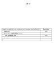
- FIG. 10 is a diagram showing one form of syntax for encoding and decoding side information in the side information encoding device 81 and the side information decoding device 91 of this embodiment.
- This example shows an SEI called image_recognition_post_processing_sei_message.
- the purpose of this SEI is to perform post-image processing on the picture by the post-image processing device 1002 and to improve recognition accuracy when the image recognition device 51 performs image recognition processing. Therefore, it is an SEI message to be encoded and decoded using network parameters for post-image processing as auxiliary information, and has the number of bytes of the value of payloadSize.
- region_id is an index value that represents the type of recognition target, which is the same as in Fig. 8. Allocation of index values is determined according to recognition targets in the image recognition device 51 . Alternatively, it may be defined as an index value that identifies an area for each recognition target within the screen.
- nnr_payload_byte is network parameter information, and is a value that expresses in bytes the data that encodes the network parameters used for post-image processing.
- the encoded data length is (payloadSize-1) bytes.
- payloadSize is a number that represents the number of bytes of SEI data.
- Neural network parameters are expressed in standard formats such as ONNX (Open Neural Network eXchange), NNEF (Neural Network Exchange Format), MPEG NNC (Moving Picture Experts Group Neural Network Coding), as well as formats such as tensorflow and pytorch. It is encoded and decoded in a library-dependent format.
- the auxiliary information creating device 71, the auxiliary information encoding device 81, and the auxiliary information decoding device 91 may hold general-purpose network parameters in common.
- the auxiliary information generating device 71 generates network parameters for partially updating the commonly held general-purpose network as auxiliary information, encodes them in the auxiliary information encoding device 81, and decodes them in the auxiliary information decoding device 91. good. With such a configuration, the code amount of the auxiliary information can be reduced, and the auxiliary information corresponding to the input image T can be created, encoded, and decoded.
- a parameter (identifier) indicating the format may be sent in order to support multiple formats.
- the actual auxiliary information following the identifier may be transmitted as a byte string.
- the network parameter auxiliary information decoded by the auxiliary information decoding device 91 is input to the post-image processing device 1002 .
- the post-image processing device 1002 uses the decoded auxiliary information to perform post-image processing using a neural network to restore the decoded moving image Td.
- post-image processing may be performed only on the recognition target candidate region by using the information of the region_id of the image recognition assistance SEI simultaneously with the auxiliary information of the image recognition assistance SEI shown in FIG.
- Encoding and decoding of network parameters are not limited to SEI, and syntax such as SPS, PPS, APS, and slice header may be used.
- the auxiliary encoding device 81 encodes the auxiliary information based on the syntax tables shown in FIG. 8, FIG. 10, or FIGS. 11 and 12. 8 or 10, the auxiliary information is coded as auxiliary extension information SEI, multiplexed with the coded data Te output from the image coding device 11, and output to the network .
- the auxiliary information is coded as APS and output as part of the coded data Te output by the image coding device 11.
- FIG. 8 or 10 the auxiliary information is coded as auxiliary extension information SEI, multiplexed with the coded data Te output from the image coding device 11, and output to the network .
- the auxiliary information is coded as APS and output as part of the coded data Te output by the image coding device 11.
- Auxiliary information decoding device 91 decodes auxiliary information from encoded data Te based on the syntax tables of FIGS. Send to device 51.
- the side information decoding device 91 decodes the side information encoded as the side extension information SEI.
- the side information decoding device 91 decodes the side information encoded as APS.
- the post-image processing device 1002 performs post-image processing on the decoded moving image Td using the decoded moving image Td and auxiliary information to generate post-image processing To.
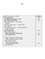
- FIG. 11 is a diagram showing an example of a syntax table obtained by extending APS (Adaptation Parameter Set) for image recognition extension in the present embodiment. The following syntax elements may be included as shown in FIG.
- aps_extension_flag is a flag indicating that there is APS extension data. If aps_extension_flag is 1, image_recognition_extension_flag is encoded. If aps_extension_flag is 0, there is no APS extension data, so image_recognition_extension_flag is not coded and is assumed to be 0.
- image_recognition_extension_flag is a flag indicating that image recognition extension data exists. It is also a flag indicating whether to encode/decode the syntax of image_recognition_extension_data(). If image_recognition_extension_flag is 1, encode/decode the syntax of image_recognition_extension_data(). image_recognition_extension_data() is a syntax containing image recognition auxiliary information.
- Fig. 12 is an example of the syntax of image_recognition_extension_data(), one of the extension information of APS.
- image_recognition_extension_data() contains network parameter information used for image recognition extension.
- This APS extension data is to improve the recognition accuracy and reduce the amount of processing when the image recognition device processes the picture. Therefore, the type, position, and size of the recognition target for the picture are described as auxiliary information.
- image_recognition_idc is an index value that indicates the type of image recognition processing.
- image_recognition_idc When the value of image_recognition_idc is 0, it is assumed that there is no recognition target in the relevant picture, and information on recognition regions and information on network parameters for post-image processing are not described. In this example, if the value of image_recognition_idc is 1, describe the information of the recognition area. Note that image_recognition_idc may add a syntax element of auxiliary information according to the type of image recognition processing.
- image_recognition_idc If the value of image_recognition_idc is 1, describe the information of the recognition area, so describe the same syntax as the image recognition assistance SEI in Fig. 8.
- number_of_region_minus1 is a syntax element that represents the number of recognition regions minus one. Describe the type, position, and size information of the recognition target for the number of values of number_of_region_minus1 plus 1.
- region_id is an index value that represents the type of recognition target. Allocation of index values is determined according to recognition targets in the image recognition device. For example, when an image recognition device detects a person, if the value of region_id is 0, the recognition target is a person, and if the value of region_id is 1, the recognition target is something else. For example, when an image recognition device recognizes a person, a bicycle, and a car, if the region_id value is 0, the recognition target is a person, if the region_id value is 1, the recognition target is a bicycle, and if the region_id value is 2, the recognition target is a person. If the value of region_id is 3, the recognition target is anything else.
- region_x and region_y are syntax elements that indicate the position of the recognition target.
- region_x is the x coordinate value (horizontal direction) of the upper left luminance of the rectangular region.
- region_y is the y coordinate value (vertical direction) of the upper left luminance of the rectangular region.
- region_width and region_hight are syntax elements that indicate the size of recognition correspondence.
- region_width is the number of pixels of luminance in the horizontal direction of the rectangular region. Note that the value of region_x+region_width shall not exceed the number of pixels in the horizontal direction of the picture.
- region_hight is the number of pixels of luminance in the vertical direction of the rectangular region. Note that the value of region_y+region_height shall not exceed the number of pixels in the vertical direction of the picture.
- the recognition target area is a rectangle, and a method of representing the upper left coordinate value of the rectangle and the number of pixels in the horizontal and vertical directions is shown, but another method may be used for the recognition target area.
- the position information of the rectangle may be the upper right, lower left, lower right, or center of gravity instead of the upper left of the rectangular area.
- the rectangle it is also possible to specify only the number of pixels on one side by limiting to a square.
- a CTU address or the number of CTUs, which are encoding units, may be used instead of rectangles and squares.
- the post_processing_data_flag is a flag indicating whether or not the post-image processing device 1002 performs post-image processing on the decoded moving image Td. If TRUE, describe the network parameter information used for post-image processing.
- payloadSize is a number that represents the number of bytes of network parameters.
- nnr_payload_byte is network parameter information, and is a value that expresses in bytes the data that encodes the network parameters used for post-image processing.
- the encoded data length is payloadSize bytes.
- Neural network parameters are expressed in standard formats such as ONNX (Open Neural Network eXchange), NNEF (Neural Network Exchange Format), MPEG NNC (Moving Picture Experts Group Neural Network Coding), as well as formats such as tensorflow and pytorch. It is encoded and decoded in a library-dependent format.
- rbsp_trailing_bits() adds 1 to 8 bits of data so that the number of APS bits is in bytes.
- the auxiliary information creating device 71, the auxiliary information encoding device 81, and the auxiliary information decoding device 91 may hold general-purpose network parameters in common.
- the auxiliary information generating device 71 generates network parameters for partially updating the commonly held general-purpose network as auxiliary information, encodes them in the auxiliary information encoding device 81, and decodes them in the auxiliary information decoding device 91. good. With such a configuration, the code amount of the auxiliary information can be reduced, and the auxiliary information corresponding to the input image T can be created, encoded, and decoded.
- a parameter (identifier) indicating the format may be sent in order to support multiple formats.
- the actual auxiliary information following the identifier may be transmitted as a byte string.
- the network parameter auxiliary information decoded by the auxiliary information decoding device 91 is input to the post-image processing device 1002 .
- the post-image processing device 1002 uses a neural network to perform post-image processing of the recognition target candidate area. As a result, the image quality of the decoded moving image Td of the recognition target candidate area is improved, and the recognition accuracy of the image recognition device is improved.
- the syntax in APS was shown, but it is not limited to APS, and syntax such as SPS, PPS, slice header, etc. may be used.
- part of the image encoding device 11 and the image decoding device 31 in the above-described embodiment for example, the entropy decoding unit 301, the parameter decoding unit 302, the loop filter 305, the prediction image generation unit 308, the inverse quantization/inverse transform unit 311, addition unit 312, prediction parameter derivation unit 320, prediction image generation unit 101, subtraction unit 102, transformation/quantization unit 103, entropy coding unit 104, inverse quantization/inverse transformation unit 105, loop filter 107, coding
- the parameter determining unit 110, the parameter encoding unit 111, and the prediction parameter deriving unit 120 may be implemented by a computer.
- a program for realizing this control function may be recorded in a computer-readable recording medium, and the program recorded in this recording medium may be read into a computer system and executed.
- the “computer system” here is a computer system built into either the image encoding device 11 or the image decoding device 31, and includes hardware such as an OS and peripheral devices.
- the term "computer-readable recording medium” refers to portable media such as flexible discs, magneto-optical discs, ROMs, and CD-ROMs, and storage devices such as hard disks built into computer systems.
- “computer-readable recording medium” means a medium that dynamically stores a program for a short period of time, such as a communication line for transmitting a program via a network such as the Internet or a communication line such as a telephone line. In that case, it may also include a memory that holds the program for a certain period of time, such as a volatile memory inside a computer system that serves as a server or client. Further, the program may be for realizing part of the functions described above, or may be capable of realizing the functions described above in combination with a program already recorded in the computer system.
- part or all of the image encoding device 11 and the image decoding device 31 in the above-described embodiments may be implemented as an integrated circuit such as LSI (Large Scale Integration).
- LSI Large Scale Integration
- Each functional block of the image encoding device 11 and the image decoding device 31 may be individually processorized, or part or all of them may be integrated and processorized.
- the method of circuit integration is not limited to LSI, but may be realized by a dedicated circuit or a general-purpose processor.
- an integrated circuit based on this technology may be used.
- the moving image encoding device 10 and the moving image decoding device 30 described above can be used by being installed in various devices for transmitting, receiving, recording, and reproducing moving images.
- the moving image may be a natural moving image captured by a camera or the like, or may be an artificial moving image (including CG and GUI) generated by a computer or the like.
- Embodiments of the present invention are preferably applied to a moving image decoding device that decodes encoded image data and a moving image encoding device that generates encoded image data. be able to. Also, the present invention can be suitably applied to the data structure of encoded data generated by a video encoding device and referenced by a video decoding device.
Landscapes
- Engineering & Computer Science (AREA)
- Multimedia (AREA)
- Signal Processing (AREA)
- Compression Or Coding Systems Of Tv Signals (AREA)
Abstract
Description
以下、図面を参照しながら本発明の実施形態について説明する。
本明細書で用いる演算子を以下に記載する。
本実施形態に係る画像符号化装置11および画像復号装置31の詳細な説明に先立って、画像符号化装置11によって生成され、画像復号装置31によって復号される符号化データTeのデータ構造について説明する。
符号化ビデオシーケンスでは、処理対象のシーケンスSEQを復号するために画像復号装置31が参照するデータの集合が規定されている。シーケンスSEQは、図2に示すように、ビデオパラメータセットVPS(Video Parameter Set)、シーケンスパラメータセットSPS(Sequence Parameter Set)、ピクチャパラメータセットPPS(Picture Parameter Set)、Adaptation Parameter Set(APS)、ピクチャPICT、及び、補助拡張情報SEI(Supplemental Enhancement Information)を含んでいる。
符号化ピクチャでは、処理対象のピクチャPICTを復号するために画像復号装置31が参照するデータの集合が規定されている。ピクチャPICTは、図2に示すように、ピクチャヘッダPH、スライス0~スライスNS-1を含む(NSはピクチャPICTに含まれるスライスの総数)。
符号化スライスでは、処理対象のスライスSを復号するために画像復号装置31が参照するデータの集合が規定されている。スライスは、図2に示すように、スライスヘッダ、および、スライスデータを含んでいる。
符号化スライスデータでは、処理対象のスライスデータを復号するために画像復号装置31が参照するデータの集合が規定されている。スライスデータは、図2の符号化スライスヘッダに示すように、CTUを含んでいる。CTUは、スライスを構成する固定サイズ(例えば64x64)のブロックであり、最大符号化単位(LCU:Largest Coding Unit)と呼ぶこともある。
図2には、処理対象のCTUを復号するために画像復号装置31が参照するデータの集合が規定されている。CTUは、再帰的な4分木分割(QT(Quad Tree)分割)、2分木分割(BT(Binary Tree)分割)あるいは3分木分割(TT(Ternary Tree)分割)により、符号化処理の基本的な単位である符号化ユニットCUに分割される。BT分割とTT分割を合わせてマルチツリー分割(MT(Multi Tree)分割)と呼ぶ。再帰的な4分木分割により得られる木構造のノードのことを符号化ノード(Coding Node)と称する。4分木、2分木、及び3分木の中間ノードは、符号化ノードであり、CTU自身も最上位の符号化ノードとして規定される。
図2は、処理対象の符号化ユニットを復号するために画像復号装置31が参照するデータの集合が規定されている。具体的には、CUは、CUヘッダCUH、予測パラメータ、変換パラメータ、量子化変換係数等から構成される。CUヘッダでは予測モード等が規定される。
予測画像は、ブロックに付随する予測パラメータによって導出される。予測パラメータには、イントラ予測とインター予測の予測パラメータがある。
参照ピクチャリストは、参照ピクチャメモリ306に記憶された参照ピクチャからなるリストである。図4は、参照ピクチャおよび参照ピクチャリストの一例を示す概念図である。図4の参照ピクチャの一例を示す概念図において、矩形はピクチャ、矢印はピクチャの参照関係、横軸は時間、矩形中のI、P、Bは各々イントラピクチャ、単予測ピクチャ、双予測ピクチャ、矩形中の数字は復号順を示す。図に示すように、ピクチャの復号順は、I0、P1、B2、B3、B4であり、表示順は、I0、B3、B2、B4、P1である。図4には、ピクチャB3(対象ピクチャ)の参照ピクチャリストの例を示されている。参照ピクチャリストは、参照ピクチャの候補を表すリストであり、1つのピクチャ(スライス)が1つ以上の参照ピクチャリストを有してもよい。図の例では、対象ピクチャB3は、L0リストRefPicList0およびL1リストRefPicList1の2つの参照ピクチャリストを持つ。個々のCUでは、参照ピクチャリストRefPicListX(X=0または1)中のどのピクチャを実際に参照するかをrefIdxLXで指定する。図は、refIdxL0=2、refIdxL1=0の例である。なお、LXは、L0予測とL1予測を区別しない場合に用いられる記述方法であり、以降では、LXをL0、L1に置き換えることでL0リストに対するパラメータとL1リストに対するパラメータを区別する。
本実施形態に係る画像復号装置31(図5)の構成について説明する。
図6は、画像復号装置31の概略的動作を説明するフローチャートである。
次に、本実施形態に係る画像符号化装置11の構成について説明する。図7は、本実施形態に係る画像符号化装置11の構成を示すブロック図である。画像符号化装置11は、予測画像生成部101、減算部102、変換・量子化部103、逆量子化・逆変換部105、加算部106、ループフィルタ107、予測パラメータメモリ(予測パラメータ記憶部、フレームメモリ)108、参照ピクチャメモリ(参照画像記憶部、フレームメモリ)109、符号化パラメータ決定部110、パラメータ符号化部111、予測パラメータ導出部120、エントロピー符号化部104を含んで構成される。
図8は、本実施形態の補助情報符号化装置81及び補助情報復号装置91で符号化、復号する補助情報のシンタックスの一形態を示す図である。この例では、image_recognition_hint_sei_messageというSEIを示す。このSEIは、当該ピクチャに対して、画像認識装置が処理を行うにあたって認識精度の向上や、処理量の削減を目的としている。そのために、当該ピクチャに対する認識対象の種類、位置、大きさの少なくとも1つを、補助情報として符号化、復号するSEIメッセージであり、payloadSizeの値のバイト数を有する。
図9は、本実施に係る別の動画像伝送システムの構成を示す概略図である。
図10は、本実施形態の補助情報符号化装置及81及び補助情報復号装置91で補助情報符号化、復号するシンタックスの一形態を示す図である。この例では、image_recognition_post_processing_sei_messageというSEIを示す。このSEIは、当該ピクチャに対して、ポスト画像処理装置1002でポスト画像処理を行い、画像認識装置51が画像認識処理を行うにあたって認識精度の向上させることを目的としている。そのために、ポスト画像処理のためのネットワークパラメータを補助情報として、符号化、復号するSEIメッセージであり、payloadSizeの値のバイト数を持つ。
なお、ネットワークパラメータの符号化、復号は、SEI限定されず、SPS、PPS、APS、スライスヘッダなどのシンタックスを用いてもよい。
図11は、本実施の形態における画像認識拡張のためのAPS(Adaptation Parameter Set)を拡張したシンタックス表の一例を示す図である。図12に示すように以下のシンタックス要素が含まれ得る。
上述した動画像符号化装置10及び動画像復号装置30は、動画像の送信、受信、記録、再生を行う各種装置に搭載して利用することができる。なお、動画像は、カメラ等により撮像された自然動画像であってもよいし、コンピュータ等により生成された人工動画像(CGおよびGUIを含む)であってもよい。
Claims (8)
- 符号化データから画像を復号する画像復号装置であって、
復号した画像の認識対象の位置、大きさ及び種類の少なくとも1つを示す補助情報を復号する補助情報復号部を少なくとも備えることを特徴とする動画像復号装置。 - 前記補助情報復号部は、前記補助情報として、認識対象領域の画像復元に用いるネットワークパラメータを復号することを特徴とする請求項1に記載の動画像復号装置。
- 画像の認識対象の位置、大きさ及び種類の少なくとも1つを示す補助情報を復号する補助情報復号部から復号されたネットワークパラメータを用いて、ポスト画像処理を行うことを特徴とするポスト画像処理装置。
- 前記補助情報が示す候補領域のみにポスト画像処理を行うことを特徴とする請求項3に記載のポスト画像処理装置。
- 入力画像を符号化する画像符号化装置であって、
前記入力画像の認識対象の位置、大きさ及び種類の少なくとも1つを示す補助情報を符号化する補助情報符号化部を少なくとも備えることを特徴とする動画像符号化装置。 - 前記補助情報符号化部は、前記補助情報として、認識対象領域の画像復元に用いるネットワークパラメータを符号化することを特徴とする請求項5に記載の動画像符号化装置。
- 符号化データから画像を復号する画像復号方法であって、
復号した画像の認識対象の位置、大きさ及び種類の少なくとも1つを示す補助情報を復号するステップを少なくとも含むことを特徴とする動画像復号方法。 - 入力画像を符号化する画像符号化方法であって、
前記入力画像の認識対象の位置、大きさ及び種類の少なくとも1つを示す補助情報を符号化するステップを少なくとも含むことを特徴とする動画像符号化方法。
Priority Applications (1)
| Application Number | Priority Date | Filing Date | Title |
|---|---|---|---|
| US18/719,272 US20250071330A1 (en) | 2021-12-14 | 2022-12-07 | Video decoding apparatus, post-image processing apparatus, video coding apparatus, video decoding method, and video coding method |
Applications Claiming Priority (2)
| Application Number | Priority Date | Filing Date | Title |
|---|---|---|---|
| JP2021202161A JP2025014089A (ja) | 2021-12-14 | 2021-12-14 | 動画像符号化装置、復号装置 |
| JP2021-202161 | 2021-12-14 |
Publications (1)
| Publication Number | Publication Date |
|---|---|
| WO2023112784A1 true WO2023112784A1 (ja) | 2023-06-22 |
Family
ID=86774548
Family Applications (1)
| Application Number | Title | Priority Date | Filing Date |
|---|---|---|---|
| PCT/JP2022/045001 Ceased WO2023112784A1 (ja) | 2021-12-14 | 2022-12-07 | 動画像復号装置、ポスト画像処理装置、動画像符号化装置、動画像復号方法及び動画像符号化方法 |
Country Status (3)
| Country | Link |
|---|---|
| US (1) | US20250071330A1 (ja) |
| JP (1) | JP2025014089A (ja) |
| WO (1) | WO2023112784A1 (ja) |
Citations (2)
| Publication number | Priority date | Publication date | Assignee | Title |
|---|---|---|---|---|
| WO2018043143A1 (ja) * | 2016-08-30 | 2018-03-08 | ソニー株式会社 | 送信装置、送信方法、受信装置および受信方法 |
| US20210084096A1 (en) * | 2018-05-30 | 2021-03-18 | Huawei Technologies Co., Ltd. | Video processing method and apparatus |
-
2021
- 2021-12-14 JP JP2021202161A patent/JP2025014089A/ja active Pending
-
2022
- 2022-12-07 US US18/719,272 patent/US20250071330A1/en not_active Abandoned
- 2022-12-07 WO PCT/JP2022/045001 patent/WO2023112784A1/ja not_active Ceased
Patent Citations (2)
| Publication number | Priority date | Publication date | Assignee | Title |
|---|---|---|---|---|
| WO2018043143A1 (ja) * | 2016-08-30 | 2018-03-08 | ソニー株式会社 | 送信装置、送信方法、受信装置および受信方法 |
| US20210084096A1 (en) * | 2018-05-30 | 2021-03-18 | Huawei Technologies Co., Ltd. | Video processing method and apparatus |
Non-Patent Citations (2)
| Title |
|---|
| DUAN LINGYU; LIU JIAYING; YANG WENHAN; HUANG TIEJUN; GAO WEN: "Video Coding for Machines: A Paradigm of Collaborative Compression and Intelligent Analytics", IEEE TRANSACTIONS ON IMAGE PROCESSING, IEEE, USA, vol. 29, 28 August 2020 (2020-08-28), USA, pages 8680 - 8695, XP011807613, ISSN: 1057-7149, DOI: 10.1109/TIP.2020.3016485 * |
| J. BOYCE, Y.-K. WANG, G. J. SULLIVAN (MICROSOFT): "Annotated Regions SEI message for HEVC (Draft 1)", 31. JCT-VC MEETING; 20180414 - 20180420; SAN DIEGO; (JOINT COLLABORATIVE TEAM ON VIDEO CODING OF ISO/IEC JTC1/SC29/WG11 AND ITU-T SG.16 ), 23 June 2018 (2018-06-23), XP030198542 * |
Also Published As
| Publication number | Publication date |
|---|---|
| JP2025014089A (ja) | 2025-01-29 |
| US20250071330A1 (en) | 2025-02-27 |
Similar Documents
| Publication | Publication Date | Title |
|---|---|---|
| US12470707B2 (en) | Reusing adaptive loop filter (ALF) sub-picture boundary processing for raster-scan slice boundaries | |
| KR102408765B1 (ko) | 비디오 코딩 및 디코딩 | |
| KR102809083B1 (ko) | Aps 시그널링 기반 비디오 또는 영상 코딩 | |
| KR102889120B1 (ko) | 적응적 루프 필터를 적용하는 비디오 또는 영상 코딩 | |
| JP2024002451A (ja) | 動画像符号化装置、動画像復号装置 | |
| WO2019079117A1 (en) | CHROMINANCE QUANTIFICATION PARAMETER (QP) SHIFT | |
| WO2018035127A1 (en) | Intra video coding using a decoupled tree structure | |
| JP2023096354A (ja) | 動画像符号化装置、動画像復号装置 | |
| WO2018035130A1 (en) | Intra video coding using a decoupled tree structure | |
| CN110463202A (zh) | 色彩分量当中的滤波器信息共享 | |
| JP7846554B2 (ja) | 動画像符号化装置、動画像復号装置および集積回路 | |
| CA2951522A1 (en) | Extensible design of nesting supplemental enhancement information (sei) messages | |
| CN115398920A (zh) | 用于颜色格式支持的自适应环路滤波 | |
| CN115956362A (zh) | 跨分量样点自适应偏移中的色度编码增强 | |
| KR102849557B1 (ko) | 루마 맵핑 및 크로마 스케일링 기반 비디오 또는 영상 코딩 | |
| CN115699748A (zh) | 经解码图片缓冲器(dpb)操作和接入单元定界符(aud) | |
| JP2024513160A (ja) | クロスコンポーネントサンプル適応型オフセットにおける符号化向上 | |
| JP2024520401A (ja) | 方法、電子装置、コンピュータ可読ストレージ媒体、コンピュータプログラム、およびビットストリーム | |
| WO2019065488A1 (ja) | 画像復号装置および画像符号化装置 | |
| KR20210158391A (ko) | 루마 샘플들의 맵핑 및 크로마 샘플들의 스케일링 기반 비디오 또는 영상 코딩 | |
| EP4349014A1 (en) | Coding enhancement in cross-component sample adaptive offset | |
| CN116671105A (zh) | 具有虚拟边界的跨分量样点自适应偏移中的色度编解码增强 | |
| WO2023136257A1 (ja) | 動画像符号化装置、動画像復号装置 | |
| JP2024047918A (ja) | 動画像符号化装置、動画像復号装置 | |
| WO2023112784A1 (ja) | 動画像復号装置、ポスト画像処理装置、動画像符号化装置、動画像復号方法及び動画像符号化方法 |
Legal Events
| Date | Code | Title | Description |
|---|---|---|---|
| 121 | Ep: the epo has been informed by wipo that ep was designated in this application |
Ref document number: 22907311 Country of ref document: EP Kind code of ref document: A1 |
|
| WWE | Wipo information: entry into national phase |
Ref document number: 18719272 Country of ref document: US |
|
| NENP | Non-entry into the national phase |
Ref country code: DE |
|
| 122 | Ep: pct application non-entry in european phase |
Ref document number: 22907311 Country of ref document: EP Kind code of ref document: A1 |
|
| NENP | Non-entry into the national phase |
Ref country code: JP |
|
| WWP | Wipo information: published in national office |
Ref document number: 18719272 Country of ref document: US |