WO2023112301A1 - 計量装置の防水機構 - Google Patents
計量装置の防水機構 Download PDFInfo
- Publication number
- WO2023112301A1 WO2023112301A1 PCT/JP2021/046702 JP2021046702W WO2023112301A1 WO 2023112301 A1 WO2023112301 A1 WO 2023112301A1 JP 2021046702 W JP2021046702 W JP 2021046702W WO 2023112301 A1 WO2023112301 A1 WO 2023112301A1
- Authority
- WO
- WIPO (PCT)
- Prior art keywords
- pan
- boss
- weighing
- waterproof
- surrounding member
- Prior art date
- Legal status (The legal status is an assumption and is not a legal conclusion. Google has not performed a legal analysis and makes no representation as to the accuracy of the status listed.)
- Ceased
Links
Images


Classifications
-
- G—PHYSICS
- G01—MEASURING; TESTING
- G01G—WEIGHING
- G01G21/00—Details of weighing apparatus
- G01G21/30—Means for preventing contamination by dust
-
- G—PHYSICS
- G01—MEASURING; TESTING
- G01G—WEIGHING
- G01G21/00—Details of weighing apparatus
- G01G21/28—Frames, Housings
Definitions
- This invention relates to a waterproof mechanism for a weighing device.
- a balance which is a weighing device, has a mass sensor in the device case of the balance, and transmits the load applied to the weighing pan to the mass sensor for weighing.
- the following means are known for waterproofing the area around the weighing pan and preventing water from entering the mass sensor. (1) Seal the connection between the weighing pan and the mass sensor to keep it waterproof at all times. (2) Seal the connection between the weighing pan and the mass sensor only when cleaning the balance.
- Patent Document 1 As for the above (1), it is well known that the connecting portion is covered with a diaphragm, as in Patent Document 1. As for the above (2), it is well known to cover the connecting portion with a dedicated rubber cap. Alternatively, there is also Patent Document 2, in which a connecting portion is provided with a structure capable of supplying air pressure, and air is introduced during cleaning to seal the space between the weighing pan and the mass sensor.
- JP 2013-11489 A Japanese Patent Application Laid-Open No. 2001-349770
- a constant waterproof mechanism using a diaphragm has the problem that the width (size) of the device is required for the diameter of the diaphragm. Also, the diaphragm is good for cleaning, but for a balance with a minimum display of 0.1 mg or less, for example, there is a problem that pressure fluctuations in the diaphragm cause fluctuations, resulting in unstable weighing values.
- a waterproof mechanism using a rubber cap or a waterproof mechanism using air pressure requires a rubber cap and a pneumatic jig that are required only for cleaning, and there are problems such as loss of these jigs and inconvenient management.
- the present invention has been made to solve the above problems, and an object of the present invention is to provide a waterproof mechanism for waterproofing a mass sensor of a weighing device without using a diaphragm or a special jig.
- a waterproof mechanism for a weighing device includes a weighing pan, a mass sensor to which the load of the weighing pan is transmitted, a device case accommodating the mass sensor, and the weighing device.
- a waterproof material is arranged in the circumferential direction on each of the upper surface of the countersunk boss surrounding member and the contact surface of the countersunk boss surrounding member that contacts the device case.
- the inner side surface of the side wall portion and the outer side surface of the countersunk boss surrounding member are provided with mutually engaging threads, and the side wall portion and the countersink boss surrounding member are screwed together by turning the weighing pan in a threaded direction. It is also preferable to engage as described above.
- the lower end portion of the inner side surface of the side wall portion and the outer side surface of the countersunk boss surrounding member are provided with engaging portions that engage with each other in an uneven manner, and the side wall portion and the countersink boss surrounding member are engaged by the unevenness. It is also preferable to
- the outer side surface of the countersunk boss peripheral member includes a first outer side surface that guides the downward movement of the side wall portion, and a second outer side surface that is larger in diameter than the first outer side surface and located below the first outer side surface. It is also preferable that side surfaces are provided, and a step between the first outer side surface and the second outer side surface restricts the descent of the side wall portion and prevents the waterproof material from being crushed too much.
- the lower end of the side wall interferes with the outer side surface of the pan boss surrounding member, and it is also preferable to prevent the overload from being transmitted to the mass sensor.
- the waterproof mechanism for a weighing device includes an elastic body between the dish boss and the dish holder of the dish boss for urging the dish boss in a direction away from the dish receiver, wherein the elastic body It is also preferable to combine with an overload protection mechanism that releases the load by separating the dish boss from the dish receiver.
- the weighing pan when the weighing pan is lowered by the specified amount and the engagement is achieved, the weighing pan is fixed to the pan boss peripheral member, and the pan boss peripheral member acts as a stopper for the weighing pan during transportation of the device. It is also preferable to become
- Fig. 1 shows a weighing device provided with a waterproof mechanism for weighing device according to a first embodiment of the present invention, comprising (a) a plan view of the weighing device, (b) a left side view of the weighing device, and (c) a weighing device. It is a vertical cross-sectional view of. It is a perspective view of the waterproof mechanism for the weighing device. It is an exploded perspective view of the waterproof mechanism for the weighing device. It is a perspective view of the weighing pan of the waterproof mechanism for the same weighing device. It is a perspective view of a countersunk boss surrounding member of the waterproof mechanism for the same weighing device.
- FIG. 7 is a vertical cross-sectional view of the waterproof mechanism for a weighing device according to the second embodiment of the present invention when waterproof. It is a longitudinal cross-sectional view of a waterproof mechanism for a weighing device according to Modification 1 of the embodiments.
- FIGS. 1A and 1B are diagrams showing a "weighing device" having a waterproof mechanism for a weighing device according to a first embodiment.
- FIG. (c) is a vertical cross-sectional view of the weighing device (cross-sectional view taken along the line cc shown in b).
- Reference numeral 1 is a weighing device, and the weighing device 1 is an electronic balance (hereinafter referred to as balance 1).
- the balance 1 includes a device case 10 , a weighing pan 11 , a mass sensor 12 and a pan boss surrounding member 13 .
- the device case 10 is made of aluminum die-cast, zinc die-cast, or stainless steel.
- the device case 10 has a divided structure of an upper case 10u and a lower case 10d, and the upper case 10u and the lower case 10d are fitted together with a sealing material such as packing interposed therebetween.
- a waterproof connector 15 is fixed to the upper case 10u, and a power cable, an RS232C cable, and the like are attached.
- the mass sensor 12 is housed in the device case 10.
- the mass sensor 12 includes a Roberval mechanism 121 and a sensor body 122 .
- the Roberval mechanism 121 is a structure for transmitting the load received by the weighing pan 11 to the sensor main body 122, and is formed of a rectangular metal block. a fixed part, upper and lower secondary rods connecting the floating part and the fixed part, and a load transmitting part for transmitting the load acting on the floating part to the sensor main body 122.
- the sensor body 122 is shown as an electromagnetic balance sensor in this embodiment, it is not limited to this, and may be, for example, a strain gauge sensor or a capacitance sensor.
- the weighing pan 11 is downwardly supported by the Roberval mechanism 121 via the upwardly convex dish boss 14, and is arranged above the device case 10.
- a plate receiver 16 is fixed to the floating portion of the Roberval mechanism 121.
- the plate receiver 16 is formed with a concave portion in which the lower end portion of the plate boss 14 is received.
- An elastic body 17 is arranged between the plate boss 14 and the plate receiver 16 to urge the plate boss 14 in a direction away from the plate receiver 16 .
- the countersink boss 14 is biased by an elastic body 17 and is arranged in a state of being locked by a countersink boss retainer 18 arranged on the upper surface of the countersunk receiver 16 .
- the pan boss 14 sinks downward, and the elastic body 17 separates the pan boss 14 from the pan receiver 16 , so that the overload is not transmitted to the mass sensor 12 .
- the countersink boss 14, elastic body 17, countersink receiver 16, and countersunk boss retainer 18 are known overload prevention mechanisms. The details of this can be cited from Japanese Patent No. 6414864.
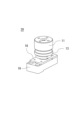
- FIG. 2 is a perspective view of the waterproof mechanism for the weighing device according to the first embodiment
- FIG. 3 is an exploded perspective view of the waterproof mechanism for the weighing device
- FIG. 4 is a perspective view of the weighing pan of the waterproof mechanism for the weighing device
- 5 is a perspective view of a countersunk boss peripheral member of the waterproof mechanism for the weighing device
- FIG. 6 is a longitudinal sectional view of the waterproof mechanism for the weighing device after assembly.
- a waterproof mechanism for a weighing device (hereinafter referred to as a "waterproof mechanism") 20 mainly includes a weighing pan 11, a pan boss surrounding member 13, a pan boss 14, a pan boss holder 18, and a pan receiver 16.
- a weighing pan 11 mainly includes a weighing pan 11, a pan boss surrounding member 13, a pan boss 14, a pan boss holder 18, and a pan receiver 16.
- the weighing pan 11 is fixed to the pan boss 14 with screws 101 .
- the countersunk boss surrounding member 13 is fixed under the upper case 10u by a nut 102.
- the countersink boss 14 includes an elastic body 17 and is engaged with a countersunk boss retainer 18 and a screw 103 to be placed on the countersink receiver 16 .
- the weighing pan 11 has a bottomed cylindrical shape as a whole, and includes a flat plate portion 111 and a side wall portion 112 extending downward from the peripheral edge of the plate portion 111 .
- a screw hole for the screw 101 is formed in the center of the plate portion 111, and a plurality of screw holes for attaching a tare, for example, are formed in the plate portion 111 around it.
- An inner side surface 1121 (see FIG. 6) of the side wall portion 112 is circumferentially formed with a female threaded portion (not shown) that engages with the male threaded portion of the countersunk boss peripheral member 13 . This female threaded portion is the "threaded portion" in the claims.
- the weighing pan 11 is preferably made of metal such as stainless steel.
- the countersunk boss surrounding member 13 is cylindrical as a whole and has a hollow portion 131 .
- the countersunk boss 14 is inserted through the hollow portion 131 .
- the countersink boss surrounding member 13 includes a first waterproof portion 132, a countersink guide portion 133, a second waterproof portion 134, and a fixing portion 135 around the hollow portion 131 from above.
- the disk boss surrounding member 13, that is, the hollow portion 131, the first waterproof portion 132, the disk guide portion 133, the second waterproof portion 134, and the fixing portion 135 are preferably integrally formed of metal such as stainless steel.
- the first waterproof part 132 is a cylindrical part at the upper end of the countersunk boss surrounding member 13 .
- a concave portion (hereinafter referred to as a “waterproof concave portion”) 1322 is formed in the circumferential direction on an upper surface 1321 (see FIG. 6) of the first waterproof portion 132, and a ring-shaped packing is provided in the waterproof concave portion 1322 as the waterproof material 104. is placed.
- the diameter of the first waterproof portion 132 is set to such a size that (the side wall portion 112 of) the weighing pan 11 does not come into contact with the pan boss surrounding member 13 during weighing.
- the disk guide part 133 is a cylindrical part formed below the first waterproof part 132 and having a larger diameter than the first waterproof part 132 .
- the outer diameter of the plate guide portion 133 is set to approximately match the inner diameter of the side wall portion 112 of the weighing plate 11 .
- a side surface 1331 of the disc guide portion 133 (hereinafter referred to as a “first outer side surface”.
- the first outer side surface 1331 is the “outer side surface” in the claims) has a female screw portion of the side wall portion 112 in the circumferential direction.
- a male threaded portion for screwing is formed (not shown). This externally threaded portion is the “threaded portion” in the claims.
- the second waterproof part 134 is a cylindrical part formed below the disk guide part 133 and having a larger diameter than the disk guide part 133 .
- the side surface of the second waterproof portion 134 is hereinafter referred to as a "second outer side surface” 1341 (the second outer side surface 1341 is the “outer side surface” in the claims).
- a concave portion 1343 (see FIG. 6, hereinafter referred to as a “waterproof concave portion”) is formed in the circumferential direction on the lower surface 1342 (see FIG. 6) of the second waterproof portion 134.
- a ring-shaped packing is arranged in a state of being crushed by an appropriate amount.
- the fixed part 135 is the lower end part of the countersunk boss peripheral member 13, is formed below the second waterproof part 134, and is a cylindrical part having a smaller diameter than the second waterproof part 134.
- the fixing portion 135 is inserted through the mounting hole of the device case 10 and fixed by the nut 102 .
- the fixing portion 135 of the countersunk boss peripheral member 13 is arranged inside the device case 10, and the second waterproof portion 134, the disk guide portion 133, and the first waterproof portion 132 are arranged outside the device case 10.
- the lower surface 1342 of the second waterproof part 134 comes into contact with the upper surface of the device case 10 (hereinafter, the lower surface 1342 is referred to as the "contact surface").
- the disk boss 14 is arranged in the hollow portion 131 , and the second waterproof portion 134 , the disk guide portion 133 and the first waterproof portion 132 are arranged around the disk boss 14 .
- the weighing pan 11 is supported by the pan boss 14 and arranged above the device case 10 .
- the waterproof members 104 and 105 provided in the waterproof concave portions 1322 and 1343 are arranged above and below the countersunk boss peripheral member 13, respectively.
- the waterproof members 104 and 105 may be gaskets, sealing materials such as waterproof filters, or viscoelastic materials instead of ring-shaped packings.
- the waterproof material 105 may be an adhesive having water resistance.
- FIG. 6 also shows the state of the waterproof mechanism 20 during weighing.
- the weighing pan 11 is arranged at a position that does not come into contact with the pan boss surrounding member 13 .
- FIG. 7 is a longitudinal sectional view of the waterproof mechanism 20 when an overload is applied during weighing.
- the weighing pan 11 sinks and the inner side surface 1121 of the side wall portion 112 of the pan interferes with the first outer side surface 1331 of the pan guide portion 133 of the pan boss surrounding member 13 .
- the inner side surface 1121 and the first outer side surface 1331 have threaded portions, their threads interfere with each other, and sinking of the weighing plate 11 is prevented above the plate guide portion 133 . That is, the overload from the weighing pan 11 is transmitted to the pan boss peripheral member 13 and the device case 10, and is less likely to be transmitted to the mass sensor 12 inside the case.
- FIG. 8 is a longitudinal sectional view of the waterproof mechanism 20 when waterproof.
- the weighing pan 11 When waterproofing the balance 1, the weighing pan 11 is turned horizontally, the female threaded portion of the side wall portion 112 is screwed into the male threaded portion of the pan guide portion 133 of the pan boss surrounding member 13, and the weighing pan 11 is moved by the specified amount. lower down.
- the side wall portion 112 comes into close contact with the pan boss surrounding member 13 in the circumferential direction, and the lower surface 1111 of the pan portion 111 of the weighing pan 11 crushes the waterproof material 104 by an appropriate amount. It contacts the upper surface 1321 of the boss surrounding member 13 .
- the prescribed amount is set with a buffer that is at least two times or more and three times or less the sinking amount of the weighing pan 11 when overloaded. For example, if the amount of sinking of the weighing pan 11 when overloaded (FIG. 7) is about 1 mm, the amount of sinking of the weighing pan 11 when waterproof (FIG. 8) is set to 2 mm. By setting it to 2 times or more, it is possible to prevent the waterproof mechanism 20 from being in a waterproof state when the waterproof mechanism 20 is overloaded. Further, by setting the distance to 3 times or less, the amount by which the countersunk boss surrounding member 13 protrudes from the device case 10 is limited, making it compact and resistant to lateral impact.
- a step 136 is provided between the first outer side surface 1331 and the second outer side surface 1341. ing.
- the upper surface of the second waterproof part 134 interferes with the lower end of the side wall part 112 to restrict further lowering of the pan, thereby preventing the pan boss peripheral member 13 from being lowered further. Excessive crushing of the waterproof material 104 arranged on the upper surface 1321 is prevented.
- the waterproof mechanism 20 of this embodiment when the weighing pan 11 is lowered by a specified amount, the weighing pan 11 directly engages with the component of the device case 10 (the pan boss surrounding member 13).
- the upper and lower waterproof portions (the first waterproof portion 132 and the second waterproof portion 134) formed in the countersunk boss peripheral member 13 provide waterproofing in the circumferential direction, preventing water from entering the inside of the device case 10 (mass sensor 12). Intrusion is prevented.
- the waterproofing described above is achieved simply by turning the weighing pan 11 horizontally (tightening screws). Therefore, there is no need for a special jig for waterproofing the balance. Moreover, the weighing pan 11 and the pan-boss surrounding member 13 are made of metal, and do not use a diaphragm that contributes to unstable weighing values. Since the waterproof mechanism 20 does not use a diaphragm, the width of the device can be reduced, and it is suitable for a built-in balance in a production line.
- the waterproof material 104 that is likely to wear due to contact with the weighing pan 11 that moves up and down can be replaced by the user without relying on a trader by opening the waterproof concave portion 1322 upward. It's like Further, by providing the step 136 to the countersunk boss peripheral member 13, the waterproof material 104 is prevented from being crushed too much, so that the waterproof function of the first waterproof portion 132 is properly performed.
- the waterproof mechanism 20 of this embodiment is configured to be combined with a known overload prevention mechanism composed of the countersink boss 14, the countersink receiver 16, the elastic body 17, and the countersink boss retainer 18.
- a known overload prevention mechanism composed of the countersink boss 14, the countersink receiver 16, the elastic body 17, and the countersink boss retainer 18.
- the waterproof mechanism 20 of this embodiment also functions as a stopper during transportation.
- FIG. 8 also shows the state of the waterproof mechanism 20 during transportation of the balance 1 . Since the weighing pan is a movable part in a general balance during transportation, it is removed from the device case and packed separately from the device case. In addition, the device case is packed in a state in which the connecting portion (such as a plate boss) with the weighing pan is strictly protected. On the other hand, when the balance 1 of this embodiment is placed in the state shown in FIG. Since it functions as described above, there is no need to pack the weighing pan 11 separately or to pack the device case 10 tightly.
- FIG. 9 is a vertical cross-sectional view of a waterproof mechanism for a weighing device according to a second embodiment when waterproof.
- the waterproof mechanism 20 of the first embodiment the weighing pan 11 and the pan boss surrounding member 13 are threaded. It is configured to engage (hook engagement).
- the weighing pan 11 has a protrusion 1122 (hereinafter referred to as "engagement protrusion”) in the circumferential direction at the lower end of the inner side surface 1121 of the side wall 112 instead of the female thread.
- the weighing pan 11 is preferably made of, for example, metal or synthetic resin and has moderate elasticity.
- the countersink boss surrounding member 13 has a recess 1332 (hereinafter referred to as an “engagement recess”) in the first outer side surface 1331 of the countersunk guide portion 133 at a position below the upper surface 1321 by a specified amount in the circumferential direction.
- engagement recess are the “engaging portions” in the claims. It should be noted that the shape of the engaging portion is not limited to that illustrated, and various modifications are possible.
- the state of the waterproof mechanism 20 of this embodiment during weighing is the same as that of the first embodiment (FIG. 6).
- the engaging convex portion 1122 formed on the lower end of the side wall portion 112 interferes with the first outer side surface 1131 of the disc guide portion 133 of the disc boss surrounding member 13, and the engaging convex portion The sinking of the weighing pan 11 is prevented by the frictional resistance generated by the portion 1122 .
- the elasticity of the pan eliminates the interference between the engaging convex portion 1122 and the first outer side surface 1131, and the side wall portion 112 is guided to the pan guide portion 133. down.
- the engaging convex portion 1122 of the weighing pan 11 hooks into the engaging concave portion 1332 of the pan boss surrounding member 13, and the lower surface 1111 of the pan portion 111 of the weighing pan 11 becomes waterproof.
- 104 is compressed by an appropriate amount, and contacts the upper surface 1321 of the countersunk boss peripheral member 13 .
- the weighing pan 11 when the weighing pan 11 is lowered by a specified amount, the weighing pan 11 directly engages with the component of the device case 10 (the pan boss surrounding member 13).
- the upper and lower waterproof portions (the first waterproof portion 132 and the second waterproof portion 134 ) formed on the countersunk boss peripheral member 13 provide circumferential waterproofing to prevent water from entering the mass sensor 12 .
- the waterproofing described above can be achieved simply by engaging the weighing pan 11 in an uneven manner. Therefore, there is no need for a special jig for waterproofing the balance. Moreover, a diaphragm is not used also for the waterproof mechanism 20 of this form.
- the upper waterproof material 104 can be easily replaced, and the step 136 between the first outer side surface 1331 and the second outer side surface 1341 allows the waterproof function of the first waterproof part 132 to function properly.
- This embodiment is also configured to be combined with a known overload prevention mechanism, and has a configuration that produces interference between the pan boss surrounding member 13 and the weighing pan 11. In this respect, the overload prevention function is provided. improve.
- the pan boss surrounding member 13 serves as a stopper for the weighing pan 11, and the side wall portion 112 of the weighing pan 11 functions like a protective cap for the connecting portion (the pan boss 14). There is no need to pack or pack the device case 10 tightly.
- the waterproof mechanism 20 includes the elastic body 17 so as to be combined with a known overload protection mechanism, but the elastic body 17 is an optional element for the waterproof mechanism.
- FIG. 10 is a vertical cross-sectional view of a waterproof mechanism for a weighing device according to Modification 1 of the embodiments, and shows a case where Modification 1 is applied to the first embodiment. If the waterproof mechanism 20 is not combined with a known overload prevention mechanism, the countersunk boss 14 may be fixed directly to the floating frame side of the mass sensor 12 (Roberval mechanism 121). The same applies to the second embodiment.
- the weighing pan 11 side has a female threaded portion and the countersunk boss peripheral member 13 side has a male threaded portion as the "threaded portion”. (not shown). Even in this form, the same effects as those of the first embodiment can be obtained.
- the engagement protrusion 1122 is provided on the weighing pan 11 side
- the engagement recess 1332 is provided on the pan boss surrounding member 13 side.
- the boss peripheral member 13 side may be configured to have an engaging projection (not shown). In this case, interference is weakened when an overload is applied to the weighing pan 11 during weighing, but as a waterproof mechanism, an effect equivalent to that of the second embodiment can be obtained.
Landscapes
- Physics & Mathematics (AREA)
- General Physics & Mathematics (AREA)
- Measurement Of Levels Of Liquids Or Fluent Solid Materials (AREA)
- Measurement Of Force In General (AREA)
- Casings For Electric Apparatus (AREA)
Priority Applications (4)
| Application Number | Priority Date | Filing Date | Title |
|---|---|---|---|
| JP2023567474A JP7701471B2 (ja) | 2021-12-17 | 2021-12-17 | 計量装置の防水機構 |
| EP21968216.8A EP4450930A4 (en) | 2021-12-17 | 2021-12-17 | WATERPROOFING MECHANISM FOR A WEIGHING DEVICE |
| US18/718,763 US20250354855A1 (en) | 2021-12-17 | 2021-12-17 | Waterproof mechanism for weighing apparatus |
| PCT/JP2021/046702 WO2023112301A1 (ja) | 2021-12-17 | 2021-12-17 | 計量装置の防水機構 |
Applications Claiming Priority (1)
| Application Number | Priority Date | Filing Date | Title |
|---|---|---|---|
| PCT/JP2021/046702 WO2023112301A1 (ja) | 2021-12-17 | 2021-12-17 | 計量装置の防水機構 |
Publications (1)
| Publication Number | Publication Date |
|---|---|
| WO2023112301A1 true WO2023112301A1 (ja) | 2023-06-22 |
Family
ID=86773907
Family Applications (1)
| Application Number | Title | Priority Date | Filing Date |
|---|---|---|---|
| PCT/JP2021/046702 Ceased WO2023112301A1 (ja) | 2021-12-17 | 2021-12-17 | 計量装置の防水機構 |
Country Status (4)
| Country | Link |
|---|---|
| US (1) | US20250354855A1 (https=) |
| EP (1) | EP4450930A4 (https=) |
| JP (1) | JP7701471B2 (https=) |
| WO (1) | WO2023112301A1 (https=) |
Citations (7)
| Publication number | Priority date | Publication date | Assignee | Title |
|---|---|---|---|---|
| JPH025039U (https=) * | 1988-06-23 | 1990-01-12 | ||
| JP2001349770A (ja) | 2000-04-10 | 2001-12-21 | Mettler Toledo Ag | シーリング兼抑止装置を備えた計量秤 |
| JP2003207385A (ja) * | 2001-10-09 | 2003-07-25 | Mettler Toledo Ag | 取り外し可能なリング要素を有するバッフルシールおよびバッフルシールを備えた秤 |
| JP2003232672A (ja) * | 2002-02-06 | 2003-08-22 | Tanita Corp | 防水型秤 |
| US20050217902A1 (en) * | 2002-11-15 | 2005-10-06 | Mettler-Toledo Gmbh | Weighing module with a dust removing device |
| JP2013011489A (ja) | 2011-06-28 | 2013-01-17 | Shinko Denshi Kk | 小型台秤 |
| JP6414864B2 (ja) | 2015-03-26 | 2018-10-31 | 株式会社エー・アンド・デイ | 過負荷防止機構 |
Family Cites Families (1)
| Publication number | Priority date | Publication date | Assignee | Title |
|---|---|---|---|---|
| DE102006012841A1 (de) * | 2006-03-21 | 2007-09-27 | Robert Bosch Gmbh | Wiegeeinrichtung, insbesondere für pharmazeutische Erzeugnisse wie Hartgelatinekapseln, Tabletten oder dergleichen |
-
2021
- 2021-12-17 JP JP2023567474A patent/JP7701471B2/ja active Active
- 2021-12-17 EP EP21968216.8A patent/EP4450930A4/en active Pending
- 2021-12-17 US US18/718,763 patent/US20250354855A1/en active Pending
- 2021-12-17 WO PCT/JP2021/046702 patent/WO2023112301A1/ja not_active Ceased
Patent Citations (7)
| Publication number | Priority date | Publication date | Assignee | Title |
|---|---|---|---|---|
| JPH025039U (https=) * | 1988-06-23 | 1990-01-12 | ||
| JP2001349770A (ja) | 2000-04-10 | 2001-12-21 | Mettler Toledo Ag | シーリング兼抑止装置を備えた計量秤 |
| JP2003207385A (ja) * | 2001-10-09 | 2003-07-25 | Mettler Toledo Ag | 取り外し可能なリング要素を有するバッフルシールおよびバッフルシールを備えた秤 |
| JP2003232672A (ja) * | 2002-02-06 | 2003-08-22 | Tanita Corp | 防水型秤 |
| US20050217902A1 (en) * | 2002-11-15 | 2005-10-06 | Mettler-Toledo Gmbh | Weighing module with a dust removing device |
| JP2013011489A (ja) | 2011-06-28 | 2013-01-17 | Shinko Denshi Kk | 小型台秤 |
| JP6414864B2 (ja) | 2015-03-26 | 2018-10-31 | 株式会社エー・アンド・デイ | 過負荷防止機構 |
Non-Patent Citations (1)
| Title |
|---|
| See also references of EP4450930A4 |
Also Published As
| Publication number | Publication date |
|---|---|
| US20250354855A1 (en) | 2025-11-20 |
| EP4450930A1 (en) | 2024-10-23 |
| JPWO2023112301A1 (https=) | 2023-06-22 |
| EP4450930A4 (en) | 2025-01-15 |
| JP7701471B2 (ja) | 2025-07-01 |
Similar Documents
| Publication | Publication Date | Title |
|---|---|---|
| JP5968660B2 (ja) | 減圧弁 | |
| JP5926858B2 (ja) | 圧力検出器の取付け構造 | |
| US10874031B2 (en) | Control device | |
| WO2023112301A1 (ja) | 計量装置の防水機構 | |
| JP5673700B2 (ja) | ケース構造 | |
| CN115425350A (zh) | 一种电池箱及电池包 | |
| JP6169332B2 (ja) | 取付構造、取付部材、取付部材及び送受波器 | |
| JP7643848B2 (ja) | 炎検知器 | |
| CN211580040U (zh) | 一种摄像机 | |
| JP4753681B2 (ja) | 防水秤 | |
| JP5065984B2 (ja) | 多光軸光電センサ | |
| US4214486A (en) | Sealed casing for pressure gauge | |
| JP5277796B2 (ja) | ハーネス接続用コネクタ | |
| RU2239897C1 (ru) | Контейнер для транспортирования отработавшего ядерного топлива | |
| JP2014013429A (ja) | 減圧弁 | |
| JP3131340U (ja) | エッジスイッチ | |
| CN112576868A (zh) | 云台及摄像设备 | |
| JP6866941B2 (ja) | 圧縮機 | |
| KR900000658B1 (ko) | 방화기능을 가진 로드셀 | |
| JP6292110B2 (ja) | ケースユニット | |
| JP5046297B2 (ja) | 多光軸光電センサ | |
| US6161947A (en) | Light fixture assembly and adapter ring therefor having exterior fastening arrangements | |
| JPH10322814A (ja) | 放圧装置 | |
| CA1098338A (en) | Sealed casing for pressure gauge | |
| JPH06349463A (ja) | 電池容器 |
Legal Events
| Date | Code | Title | Description |
|---|---|---|---|
| 121 | Ep: the epo has been informed by wipo that ep was designated in this application |
Ref document number: 21968216 Country of ref document: EP Kind code of ref document: A1 |
|
| WWE | Wipo information: entry into national phase |
Ref document number: 2023567474 Country of ref document: JP |
|
| NENP | Non-entry into the national phase |
Ref country code: DE |
|
| ENP | Entry into the national phase |
Ref document number: 2021968216 Country of ref document: EP Effective date: 20240717 |
|
| WWP | Wipo information: published in national office |
Ref document number: 18718763 Country of ref document: US |