WO2023112080A1 - 試薬保管庫、および自動分析装置 - Google Patents
試薬保管庫、および自動分析装置 Download PDFInfo
- Publication number
- WO2023112080A1 WO2023112080A1 PCT/JP2021/045763 JP2021045763W WO2023112080A1 WO 2023112080 A1 WO2023112080 A1 WO 2023112080A1 JP 2021045763 W JP2021045763 W JP 2021045763W WO 2023112080 A1 WO2023112080 A1 WO 2023112080A1
- Authority
- WO
- WIPO (PCT)
- Prior art keywords
- reagent
- reagent storage
- automatic analyzer
- identification code
- disk
- Prior art date
- Legal status (The legal status is an assumption and is not a legal conclusion. Google has not performed a legal analysis and makes no representation as to the accuracy of the status listed.)
- Ceased
Links
Images


Classifications
-
- G—PHYSICS
- G01—MEASURING; TESTING
- G01N—INVESTIGATING OR ANALYSING MATERIALS BY DETERMINING THEIR CHEMICAL OR PHYSICAL PROPERTIES
- G01N35/00—Automatic analysis not limited to methods or materials provided for in any single one of groups G01N1/00 - G01N33/00; Handling materials therefor
Definitions
- the present invention relates to an automatic analyzer that analyzes samples such as blood and urine, and a reagent storage.
- Patent Document 1 describes an automatic analyzer that can use a reagent container that has an ID such as a barcode attached to the upper surface or the lower surface of the reagent container, or both.
- information such as the type of reagent is recorded on information recording media such as barcodes, which are read and used for quality control of testing.
- the location where the information recording medium is attached is not limited to the top or side of the reagent container, but is sometimes attached to the bottom.
- the information recording medium is preferably provided on the upper surface of the reagent container, and it is difficult to read the information recording medium provided on the side or bottom of the reagent container.
- the present invention includes a plurality of means for solving the above problems.
- a plurality of reagent containers each holding a reagent therein and having an identification code in which information about the reagent is recorded are provided.
- a reagent disk to be installed a main body for housing the reagent disk inside, a lid for the reagent disk covering the upper surface side of the main body, a rotation mechanism for rotating the reagent disk, a reading device for reading the identification code
- the reagent storage includes a guide for moving the reading device between the side and bottom of the reagent container installed on the reagent disk.
- the present invention it is possible to use the reagent container provided with the information recording medium on the side or the bottom without distinguishing between them, and it is possible to perform the inspection using a more correct reagent than in the past. Problems, configurations and effects other than those described above will be clarified by the following description of the embodiments.
- FIG. 1 is a diagram showing a schematic configuration of an automatic analyzer according to Example 1 of the present invention
- FIG. 3 shows an identification code on the side of a reagent container
- FIG. 4 shows the identification code on the bottom of the reagent container.
- 4 is a diagram showing a schematic configuration of a reagent storage of the automatic analyzer according to Example 1.
- FIG. 4 is a diagram showing a schematic cross-sectional configuration of a reagent storage of the automatic analyzer according to Example 1.
- FIG. 4 is a diagram showing details of a curve guide, a block, and a reading device in a reagent storage of the automatic analyzer according to Example 1.
- FIG. 4 shows a reagent information reading workflow of the automatic analyzer according to Example 1.
- FIG. 11 is a diagram showing a schematic cross-sectional configuration of a reagent storage of an automatic analyzer according to Example 4; FIG. 11 shows a reagent information reading workflow of the automatic analyzer according to Example 4.
- FIG. 11 is a diagram showing a schematic cross-sectional configuration of a reagent storage of an automatic analyzer according to Example 4; FIG. 11 shows a reagent information reading workflow of the automatic analyzer according to Example 4.
- Example 1 A first embodiment of a reagent storage and an automatic analyzer of the present invention will be described with reference to FIGS. 1 to 7.
- FIG. 1 A first embodiment of a reagent storage and an automatic analyzer of the present invention will be described with reference to FIGS. 1 to 7.
- FIG. 1 A first embodiment of a reagent storage and an automatic analyzer of the present invention will be described with reference to FIGS. 1 to 7.
- FIG. 1 A first embodiment of a reagent storage and an automatic analyzer of the present invention will be described with reference to FIGS. 1 to 7.
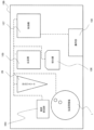
- FIG. 1 is a diagram showing a schematic configuration of an automatic analyzer according to the first embodiment.
- an automatic analyzer 100 is an apparatus for dispensing a specimen and a reagent into a reaction section 105 and measuring the physical properties of a mixed liquid prepared by reacting. It has a system 28, a reagent storage 1, a reaction section 105, a detection section 106, a control section 107, an operation section 108, and the like.
- the specimen installation section 103 has a structure for annularly installing specimen containers (not shown for convenience' sake). During sample dispensing, the sample installation unit 103 rotates to transport the sample container to the access position of the dispensing system 28 .
- the reagent storage 1 is a mechanism for storing reagent containers 14 containing reagents (see FIGS. 2 and 3), and has reagent disks 13 and the like.
- a plurality of reagent installation positions are provided on the reagent disk 13, and are configured so that a plurality of reagent containers 14 can be installed.
- the reagent disc 13 has a rotary drive mechanism, and moves each reagent container 14 to a predetermined position on the circumference by a rotary motion.
- the pipetting system 28 is composed of a rotary drive mechanism, a vertical drive mechanism, and a pipetting probe. Alternatively, it moves between the reagent aspirating position (the position of the dispensing hole 4 ) in the reagent storage 1 and the reagent discharging position in the reaction section 105 to dispense the sample from the sample container or the reagent from the reagent container 14 .
- This pipetting system 28 may be in a form in which a system dedicated to specimens and a system dedicated to reagents are provided separately or in a form in which they are shared, and are not particularly limited.
- the control unit 107 is composed of, for example, a hardware board and a computer, and incorporates a storage device such as a hard disk. In this embodiment, the controller 107 controls the operation of the reader 16 so that the identification code 15 is read when the dispensing system 28 dispenses the reagent. The details will be described later.
- the control unit 107 may be configured as hardware by a dedicated circuit board, or may be configured by software executed by a computer. When configured by hardware, it can be realized by integrating a plurality of arithmetic units for executing processing on a wiring substrate, a semiconductor chip, or a package. When configured by software, it can be realized by installing a high-speed general-purpose CPU in a computer and executing a program for executing desired arithmetic processing. It is also possible to upgrade an existing device with a recording medium in which this program is recorded. These devices, circuits, and computers are connected by a wired or wireless network, and data is transmitted and received as appropriate.
- the operation unit 108 is composed of a display device, which is a display, and input devices such as a mouse and a keyboard.
- FIG. 2 shows the identification code on the side of the reagent container
- FIG. 3 shows the identification code on the bottom of the reagent container.
- Each of the reagent containers 14 shown in FIGS. 2 and 3 is a container having a tubular side surface, holds a reagent therein, and has an identification code 15 in which information about the reagent is recorded. .
- the reagent container 14 shown in FIG. 2 has an identification code 15 formed of a two-dimensional bar code, a one-dimensional bar code, or the like attached to its side surface.
- the identification code 15 stores the container ID for identifying the reagent container 14, the type of reagent, the amount of reagent, the expiration date of the reagent, and other necessary information.
- an identification code 15 composed of a two-dimensional barcode, a one-dimensional barcode, etc. is attached to the bottom surface.
- the shape of the reagent container 14 is tubular as shown in FIGS. 2 and 3
- the shape is not particularly limited, and may be rectangular parallelepiped. Also, by having two or more separated compartments, one tube may hold two or more types of reagents.
- FIG. 4 is a diagram showing a schematic configuration of the reagent storage of the automatic analyzer according to Example 1
- FIG. 5 is a diagram showing a cross-sectional schematic configuration of the reagent storage
- FIG. 6 is a curve guide, a block, and a reader in the reagent storage. It is a diagram showing the details of.
- the reagent storage cabinet 1 includes a reagent disk 13, a main body 3, a lid 2, a fixture 5, a pot 6, a heat insulating material 7, windows 9 and 10, a rotating mechanism, a reading device 16, a curved line. It is composed of a guide 19, a block 17, a timing belt 20, a timing pulley 21, an idler pulley 22, and the like.
- the main body 3 is a container for accommodating the reagent disk 13 inside, and is composed of a heat insulating material 7 for accommodating the cauldron 6 interposed between the main body 3 and the reagent disk 13, and a transparent member for reading the identification code 15. It has one or more windows 9 on the side and one or more windows 10 on the bottom.
- the window 10 is formed on the bottom surface of the substantially disk-shaped main body 3, in the area directly below the portion where the dispensing hole 4 provided in the lid 2 is provided, in the vertical direction as if a part of the main body 3 and the heat insulating material 7 were removed. is provided.
- the window 9 is located on the side surface of the substantially disk-shaped main body 3 and is located on the outer circumferential side of the reagent disk 13 at the location where the dispensing hole 4 provided in the lid 2 is provided. It is provided as if a part of the was removed.
- These windows 9 and 10 are provided on the side surface or the bottom surface of the main body 3, respectively, but may be provided at two or more locations on the side surface or the bottom surface.
- the reader 16 is a device that reads the identification code 15 and is installed on the curve guide 19 so as to read the identification code 15 installed on the reagent disk 13 through the windows 9 and 10 .
- the reader 16 is assumed to have an imaging device such as a CMOS camera, but it is not particularly limited and may be read by oscillating a laser and using its light.
- the curved guide 19 shown in FIGS. 4 to 6 is provided on the outside of the main body 3 of the reagent storage 1, and has a window 10 capable of imaging the bottom surface of the reagent container 14 installed on the reagent disc 13, and a guide 19 of the reagent container 14. It is provided for moving between windows 9 capable of imaging the sides. Movement of the reader 16 between the window 9 and the window 10 is controlled by the controller 107 .
- This curved guide 19 is installed so that the position where the identification code 15 attached to the reagent container 14 installed inside can be seen from the window 9 or the window 10 of the reagent storage 1 is set as a trajectory. It is desirable that the identification code 15 be installed so that the identification code 15 can be confirmed through the window 9 when the identification code 15 is provided on the bottom surface, and through the window 10 when the identification code 15 is provided on the bottom surface.
- the curved guide 19 is preferably arranged so as to linearly connect the windows 9 and 10 when the automatic analyzer 100 is viewed from above in the vertical direction. It is desirable to have arcuate motion guides that are curved when viewed from the vertical direction.
- Block 17 with the reading device 16 attached moves on the curve guide 19 that draws a curve.
- Block 17 can be moved by timing belt 20 .
- the timing belt 20 is moved by a timing pulley 21 and an idler pulley 22 .
- a block 17 may be provided on the belt conveyor, the reading device 16 may be attached to the block 17, and the reading device 16 may be moved.
- reading device 16 and the curve guide 19 are not limited to being arranged outside the main body 3 and may be arranged inside the main body 3 .
- reading devices 16 may be installed within the automatic analyzer 100, it is desirable to have only one reading device 16 in the area near the reagent storage 1.
- the lid 2 covers the top side of the main body 3 and is provided with a dispensing hole 4 for the dispensing system 28 to access the reagent container 14 installed on the reagent disk 13 in the main body 3 .
- the lid 2 is provided with a fixture 5 that prevents the lid 2 from being freely opened after the reagent is placed, and can be opened and closed according to commands from a device such as an electromagnetic lock.
- the rotation mechanism rotates the reagent disk 13, and is composed of a motor 23, pulley 24, belt 25, shaft 26, pedestal 27, and the like.
- a shaft 26 is connected to the central portion of the reagent disk 13 .
- a shaft 26 is driven by a motor 23 via a pulley 24 and a belt 25 to rotate, thereby making it possible to rotate the reagent disk 13 .
- These members are held by a pedestal 27 .
- the method of rotating the reagent disk 13 is not limited to this, and may be rotated by other methods.
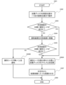
- FIG. 7 shows the reagent information reading workflow of the automatic analyzer according to the first embodiment.
- reading of the identification code 15 starts when the reagent container 14 is started to be loaded into the apparatus, for example, by manual loading by an operator or automatic loading by a reagent container transporting device. (Step 301).
- control unit 107 controls the rotation mechanism so that the position where the reagent container 14 to be read is placed is directly below the dispensing hole 4, which is the first reading position, that is, the positions of the windows 9 and 10. to rotate the reagent disk 13 and stop it (step 302).
- the reader 16 is moved to a position where the reagent container 14 can be photographed through the window 9 on the side of the main body 3 (step 302).
- step 303 If the reading is successful, the process proceeds to step 306A.
- step 304 the reading device 16 is moved to a position where the reagent container 14 can be imaged from the window 10 on the bottom surface of the main body 3 (step 304).
- the identification code 15 provided on the bottom surface of the reagent container 14 installed on the reagent disk 13 is read through the window 10 by the reading device 16, and the identification code 15 is located on the bottom surface, and the reading is successful. (step 305).
- step 306A If the reading is successful, the process proceeds to step 306A, and if the reading fails, the process proceeds to step 306B.
- step 306A When the identification code 15 is successfully read in step 303 or step 305, the address of the reagent disk 13 from which the identification code 15 is read is associated with the reagent information of the installed reagent container 14 (step 306A).
- the dispensing system 28 dispenses from the address of the reagent disk 13 containing the reagent container 14 containing the reagent having the requested reagent information (step 307). Specifically, the dispensing system 28 dispenses the reagent in the reagent container 14 through the dispensing hole 4 in the lid 2 of the reagent storage 1 .
- control unit 107 moves the reading device 16 to the position of the window 9 or window 10 on the side where the reading is successful, and also when dispensing the reagent. It is desirable to read the reagent information and confirm whether or not the correct reagent has been dispensed.
- step 306B the controller 107 is notified that the identification code 15 cannot be read.
- step 308 the workflow is terminated (step 308). If there is an unread reagent container 14 on the reagent disk 13, the processing from step 301 to step 306B is repeated.
- the reagent storage 1 in the automatic analyzer 100 of the first embodiment of the present invention described above holds reagents therein, and a plurality of reagent containers 14 each having an identification code 15 in which reagent information is recorded are installed.
- a curved guide 19 is provided to move the reader 16 between the sides and bottom of the reagent container 14 located at 13 .
- the identification code 15 attached to the reagent container 14 can be recorded in the reader while the lid 2 of the reagent storage 1 is closed. It is possible to suppress measurement failures due to mistakes more strongly than before, and to enable quality control of reagents. Moreover, even if it is not necessary to provide a plurality of readers 16, the reagent containers 14 provided with the identification code 15 for identifying the reagent on the side or the bottom can be used without discrimination.
- the reading device 16 since the reading device 16 reads the identification code 15 when the dispensing system 28 dispenses the reagent, the correct reagent can be reliably dispensed.
- the main body 3 has one or more windows 9 and 10 for reading the identification code 15 on each of its side and bottom surfaces. By reading the identification code 15 through the windows 9 and 10, it is possible to prevent the volume of the main body 3 of the reagent storage 1 from increasing.
- the curved guide 19 is curved when the reagent storage 1 is viewed from the vertical direction.
- the distance can be shortened, and the time required for processing such as reagent registration can be shortened.
- FIG. 8 is a diagram showing a schematic configuration of the reagent storage of the automatic analyzer according to the second embodiment.
- the reagent storage 1A shown in FIG. 8 is different from the reagent storage 1 of Example 1 in that it further includes a cooling device 8 and is provided with a curved guide 19A instead of the curved guide 19.
- the cooling device 8 is composed of a Peltier element or the like in the reagent storage 1 and is thermally connected to the kettle 6 to cool the interior of the kettle 6 .
- the curved guide 19A extends to the upper part of the lid 2 compared to the curved guide 19, and the highest position of the curved guide 19A in the vertical direction is the height position higher than the lid 2, and the standby position of the reading device 16. It has become.
- the reagent storage and the automatic analyzer of Example 2 of the present invention also provide substantially the same effects as the reagent storage and automatic analyzer of Example 1 described above.
- the highest position of the curved guide 19A in the vertical direction is the height position higher than the lid 2, and is the standby position of the reading device 16.
- FIG. 9 is a diagram showing a schematic configuration of the reagent storage of the automatic analyzer according to the third embodiment.
- the reagent storage 1B of this embodiment shown in FIG. 9 differs from the reagent storage 1 of Embodiment 1 in that it further includes a tilt block 18 for the reading device 16 to read the identification code 15 obliquely.
- the distance from the reader 16 to the identification code 15 is 40 mm
- the reader 16 is tilted 15 ⁇ 2° with respect to the identification code 15
- the reflected light from the reagent container 14 will interfere with the reading by the reader 16. Therefore, it is possible to further improve the reading efficiency.
- the reagent storage and the automatic analyzer of Example 3 of the present invention also provide substantially the same effects as the reagent storage and automatic analyzer of Example 1 described above.
- the reading device 16 further includes a tilt block 18 for reading the identification code 15 from an oblique angle, reading errors can be further reduced. Since the angle at which the identification code 15 can be read increases as the number of reading errors decreases, the angle at which the reagent container 14 can be placed on the reagent disk 13 can be increased, thereby enhancing convenience. play.
- tilt block 18 as in this embodiment can also be applied to the reagent storage 1A described in the second embodiment.
- FIG. 10 is a diagram showing a schematic configuration of the reagent storage of the automatic analyzer according to the fourth embodiment
- FIG. 11 is a diagram showing a cross-sectional schematic configuration of the reagent storage
- FIG. 12 is a diagram showing a workflow for reading reagent information.
- the reagent storage 1C of this embodiment shown in FIGS. 10 and 11 is configured such that the curved guide 19C moves the reading device 16 between the outer peripheral side and the inner peripheral side via the bottom surface of the reagent disk 13. It is different from the reagent storage 1 of the first embodiment in that
- the main body 3C of the reagent storage 1C has a window 9A on the inner peripheral surface side in addition to the window 9 on the outer peripheral surface side and the window 10 on the bottom surface.
- steps 1101 to 1105 are the same as steps 301 to 305 shown in FIG. 7, respectively, so details will be omitted.
- the reading device 16 is then moved to a position where the reagent container 14 can be imaged from the window 9A on the inner peripheral surface of the main body 3 (step 1105). 1106).
- the identification code 15 provided on the side surface of the reagent container 14 installed on the reagent disk 13 is read by the reading device 16 through the window 9A. is successful (step 1107). If the reading is successful, the process proceeds to step 1108A. On the other hand, if the reading fails, the process proceeds to step 1108B.
- Steps 1108A to 1110 after that are the same as steps 306A to 308 shown in FIG. 3, respectively, so the details are similarly omitted.
- the reagent storage and the automatic analyzer of Example 4 of the present invention also provide substantially the same effects as the reagent storage and automatic analyzer of Example 1 described above.
- the curved guide 19C reads the identification code attached to the reagent container 14 even on the inner peripheral side of the main body 3 by moving the reading device 16 between the outer peripheral side and the inner peripheral side via the bottom surface of the reagent disk 13 .
- 15 can be read, the angle at which the identification code 15 can be read is increased, so restrictions on the installation orientation of the reagent container 14 can be relaxed when installing the reagent container 14 in the reagent storage 1, and convenience can be further enhanced. can.
- the configuration of the curved guide 19C for moving the reading device 16 between the outer peripheral side and the inner peripheral side via the bottom surface of the reagent disk 13 as in the present embodiment is similar to the configuration of the reagent storage 1A of the second embodiment, 3 reagent storage 1B, or the reagent storage with the structure of Example 2 to Example 3.
Landscapes
- Physics & Mathematics (AREA)
- Health & Medical Sciences (AREA)
- Life Sciences & Earth Sciences (AREA)
- Chemical & Material Sciences (AREA)
- Analytical Chemistry (AREA)
- Biochemistry (AREA)
- General Health & Medical Sciences (AREA)
- General Physics & Mathematics (AREA)
- Immunology (AREA)
- Pathology (AREA)
- Automatic Analysis And Handling Materials Therefor (AREA)
Priority Applications (2)
| Application Number | Priority Date | Filing Date | Title |
|---|---|---|---|
| PCT/JP2021/045763 WO2023112080A1 (ja) | 2021-12-13 | 2021-12-13 | 試薬保管庫、および自動分析装置 |
| JP2023567278A JP7670858B2 (ja) | 2021-12-13 | 2021-12-13 | 試薬保管庫、および自動分析装置 |
Applications Claiming Priority (1)
| Application Number | Priority Date | Filing Date | Title |
|---|---|---|---|
| PCT/JP2021/045763 WO2023112080A1 (ja) | 2021-12-13 | 2021-12-13 | 試薬保管庫、および自動分析装置 |
Publications (1)
| Publication Number | Publication Date |
|---|---|
| WO2023112080A1 true WO2023112080A1 (ja) | 2023-06-22 |
Family
ID=86773948
Family Applications (1)
| Application Number | Title | Priority Date | Filing Date |
|---|---|---|---|
| PCT/JP2021/045763 Ceased WO2023112080A1 (ja) | 2021-12-13 | 2021-12-13 | 試薬保管庫、および自動分析装置 |
Country Status (2)
| Country | Link |
|---|---|
| JP (1) | JP7670858B2 (https=) |
| WO (1) | WO2023112080A1 (https=) |
Citations (9)
| Publication number | Priority date | Publication date | Assignee | Title |
|---|---|---|---|---|
| JPH0291963U (https=) * | 1988-12-29 | 1990-07-20 | ||
| JPH03162672A (ja) * | 1989-11-20 | 1991-07-12 | Shimadzu Corp | 自動分析装置の試料分注装置 |
| US5420408A (en) * | 1992-07-16 | 1995-05-30 | Schiapparelli Biosystems, Inc. | Reagent bottle identification method |
| JP2008196973A (ja) * | 2007-02-13 | 2008-08-28 | Olympus Corp | 試薬情報取得装置、試薬情報取得方法及び自動分析装置 |
| JP2008275585A (ja) * | 2007-03-30 | 2008-11-13 | Sysmex Corp | 試料分析装置 |
| JP2018059801A (ja) * | 2016-10-05 | 2018-04-12 | キヤノンメディカルシステムズ株式会社 | 自動分析装置 |
| CN108152521A (zh) * | 2016-12-05 | 2018-06-12 | 深圳华大智造科技有限公司 | 试剂存储器 |
| JP2019095254A (ja) * | 2017-11-21 | 2019-06-20 | キヤノンメディカルシステムズ株式会社 | 自動分析装置 |
| JP2019525171A (ja) * | 2015-07-23 | 2019-09-05 | メソ スケール テクノロジーズ,エルエルシー | 消耗品データ統合管理システム及びプラットフォーム |
-
2021
- 2021-12-13 JP JP2023567278A patent/JP7670858B2/ja active Active
- 2021-12-13 WO PCT/JP2021/045763 patent/WO2023112080A1/ja not_active Ceased
Patent Citations (9)
| Publication number | Priority date | Publication date | Assignee | Title |
|---|---|---|---|---|
| JPH0291963U (https=) * | 1988-12-29 | 1990-07-20 | ||
| JPH03162672A (ja) * | 1989-11-20 | 1991-07-12 | Shimadzu Corp | 自動分析装置の試料分注装置 |
| US5420408A (en) * | 1992-07-16 | 1995-05-30 | Schiapparelli Biosystems, Inc. | Reagent bottle identification method |
| JP2008196973A (ja) * | 2007-02-13 | 2008-08-28 | Olympus Corp | 試薬情報取得装置、試薬情報取得方法及び自動分析装置 |
| JP2008275585A (ja) * | 2007-03-30 | 2008-11-13 | Sysmex Corp | 試料分析装置 |
| JP2019525171A (ja) * | 2015-07-23 | 2019-09-05 | メソ スケール テクノロジーズ,エルエルシー | 消耗品データ統合管理システム及びプラットフォーム |
| JP2018059801A (ja) * | 2016-10-05 | 2018-04-12 | キヤノンメディカルシステムズ株式会社 | 自動分析装置 |
| CN108152521A (zh) * | 2016-12-05 | 2018-06-12 | 深圳华大智造科技有限公司 | 试剂存储器 |
| JP2019095254A (ja) * | 2017-11-21 | 2019-06-20 | キヤノンメディカルシステムズ株式会社 | 自動分析装置 |
Also Published As
| Publication number | Publication date |
|---|---|
| JP7670858B2 (ja) | 2025-04-30 |
| JPWO2023112080A1 (https=) | 2023-06-22 |
Similar Documents
| Publication | Publication Date | Title |
|---|---|---|
| US7964140B2 (en) | Automatic analyzer | |
| CN101162235B (zh) | 分析仪 | |
| JP5377866B2 (ja) | 検体分析装置 | |
| JP6768163B2 (ja) | 自動分析装置 | |
| US8425839B2 (en) | Sample analyzer | |
| CN101162236B (zh) | 分析装置、试剂盛放器具及试剂吸移方法 | |
| US20110232372A1 (en) | Sample analyzer and reagent information obtaining method | |
| JP7080391B2 (ja) | 自動分析装置 | |
| WO2020152991A1 (ja) | 自動分析システムおよび検体の搬送方法 | |
| JP2008096223A (ja) | 分析装置 | |
| JP4654259B2 (ja) | 自動分析装置 | |
| WO2023112080A1 (ja) | 試薬保管庫、および自動分析装置 | |
| JP7739591B2 (ja) | 自動分析装置 | |
| JP7456008B2 (ja) | 自動分析装置および自動分析装置における試薬の保管方法 | |
| JP5722406B2 (ja) | 検体分析装置 | |
| JPWO2019159609A1 (ja) | 自動分析装置 | |
| JP7066423B2 (ja) | 自動分析装置 | |
| JP2025035358A (ja) | 自動分析装置及び自動分析システム | |
| JP2025144280A (ja) | 自動分析装置 | |
| WO2024202294A1 (ja) | 自動分析装置 | |
| JP2025125903A (ja) | 試薬容器及び自動分析装置自動分析装置 | |
| CN119343604A (zh) | 自动分析装置以及自动分析装置中的信息读取方法 | |
| JPH03289566A (ja) | 自動化学分析装置 |
Legal Events
| Date | Code | Title | Description |
|---|---|---|---|
| 121 | Ep: the epo has been informed by wipo that ep was designated in this application |
Ref document number: 21968003 Country of ref document: EP Kind code of ref document: A1 |
|
| ENP | Entry into the national phase |
Ref document number: 2023567278 Country of ref document: JP Kind code of ref document: A |
|
| NENP | Non-entry into the national phase |
Ref country code: DE |
|
| 122 | Ep: pct application non-entry in european phase |
Ref document number: 21968003 Country of ref document: EP Kind code of ref document: A1 |