WO2023100489A1 - 測位装置、及び、クロック補正方法 - Google Patents
測位装置、及び、クロック補正方法 Download PDFInfo
- Publication number
- WO2023100489A1 WO2023100489A1 PCT/JP2022/038185 JP2022038185W WO2023100489A1 WO 2023100489 A1 WO2023100489 A1 WO 2023100489A1 JP 2022038185 W JP2022038185 W JP 2022038185W WO 2023100489 A1 WO2023100489 A1 WO 2023100489A1
- Authority
- WO
- WIPO (PCT)
- Prior art keywords
- communication unit
- wireless communication
- distance
- unit
- phase
- Prior art date
- Legal status (The legal status is an assumption and is not a legal conclusion. Google has not performed a legal analysis and makes no representation as to the accuracy of the status listed.)
- Ceased
Links
Images



Classifications
-
- H—ELECTRICITY
- H04—ELECTRIC COMMUNICATION TECHNIQUE
- H04W—WIRELESS COMMUNICATION NETWORKS
- H04W56/00—Synchronisation arrangements
- H04W56/004—Synchronisation arrangements compensating for timing error of reception due to propagation delay
- H04W56/005—Synchronisation arrangements compensating for timing error of reception due to propagation delay compensating for timing error by adjustment in the receiver
-
- G—PHYSICS
- G01—MEASURING; TESTING
- G01S—RADIO DIRECTION-FINDING; RADIO NAVIGATION; DETERMINING DISTANCE OR VELOCITY BY USE OF RADIO WAVES; LOCATING OR PRESENCE-DETECTING BY USE OF THE REFLECTION OR RERADIATION OF RADIO WAVES; ANALOGOUS ARRANGEMENTS USING OTHER WAVES
- G01S11/00—Systems for determining distance or velocity not using reflection or reradiation
- G01S11/02—Systems for determining distance or velocity not using reflection or reradiation using radio waves
-
- G—PHYSICS
- G01—MEASURING; TESTING
- G01S—RADIO DIRECTION-FINDING; RADIO NAVIGATION; DETERMINING DISTANCE OR VELOCITY BY USE OF RADIO WAVES; LOCATING OR PRESENCE-DETECTING BY USE OF THE REFLECTION OR RERADIATION OF RADIO WAVES; ANALOGOUS ARRANGEMENTS USING OTHER WAVES
- G01S5/00—Position-fixing by co-ordinating two or more direction or position line determinations; Position-fixing by co-ordinating two or more distance determinations
- G01S5/02—Position-fixing by co-ordinating two or more direction or position line determinations; Position-fixing by co-ordinating two or more distance determinations using radio waves
- G01S5/0257—Hybrid positioning
- G01S5/0268—Hybrid positioning by deriving positions from different combinations of signals or of estimated positions in a single positioning system
-
- G—PHYSICS
- G01—MEASURING; TESTING
- G01S—RADIO DIRECTION-FINDING; RADIO NAVIGATION; DETERMINING DISTANCE OR VELOCITY BY USE OF RADIO WAVES; LOCATING OR PRESENCE-DETECTING BY USE OF THE REFLECTION OR RERADIATION OF RADIO WAVES; ANALOGOUS ARRANGEMENTS USING OTHER WAVES
- G01S5/00—Position-fixing by co-ordinating two or more direction or position line determinations; Position-fixing by co-ordinating two or more distance determinations
- G01S5/02—Position-fixing by co-ordinating two or more direction or position line determinations; Position-fixing by co-ordinating two or more distance determinations using radio waves
- G01S5/0284—Relative positioning
-
- H—ELECTRICITY
- H04—ELECTRIC COMMUNICATION TECHNIQUE
- H04W—WIRELESS COMMUNICATION NETWORKS
- H04W64/00—Locating users or terminals or network equipment for network management purposes, e.g. mobility management
- H04W64/006—Locating users or terminals or network equipment for network management purposes, e.g. mobility management with additional information processing, e.g. for direction or speed determination
-
- G—PHYSICS
- G01—MEASURING; TESTING
- G01S—RADIO DIRECTION-FINDING; RADIO NAVIGATION; DETERMINING DISTANCE OR VELOCITY BY USE OF RADIO WAVES; LOCATING OR PRESENCE-DETECTING BY USE OF THE REFLECTION OR RERADIATION OF RADIO WAVES; ANALOGOUS ARRANGEMENTS USING OTHER WAVES
- G01S3/00—Direction-finders for determining the direction from which infrasonic, sonic, ultrasonic or electromagnetic waves, or particle emission, not having a directional significance, are being received
- G01S3/02—Direction-finders for determining the direction from which infrasonic, sonic, ultrasonic or electromagnetic waves, or particle emission, not having a directional significance, are being received using radio waves
- G01S3/14—Systems for determining direction or deviation from predetermined direction
- G01S3/46—Systems for determining direction or deviation from predetermined direction using antennas spaced apart and measuring phase or time difference between signals therefrom, i.e. path-difference systems
- G01S3/48—Systems for determining direction or deviation from predetermined direction using antennas spaced apart and measuring phase or time difference between signals therefrom, i.e. path-difference systems the waves arriving at the antennas being continuous or intermittent and the phase difference of signals derived therefrom being measured
Definitions
- the present disclosure relates to a positioning device and a clock correction method.
- a time synchronization system comprising a parent device that supplies a synchronization signal for synchronizing radio base stations, and a child device that is connected to the parent device via a transmission line having a first channel and a second channel
- the slave device includes a GPS receiver that receives a GPS (Global Positioning System) reference signal, a multiplexer that multiplexes the reference signal on a first channel of an uplink signal to the parent device, and a transmission of the uplink signal.
- a transmitting unit for transmitting over the path.
- the parent device includes: a multiplexing unit that multiplexes a delay measurement signal on a second channel of a downlink signal to the child device; a transmission unit that transmits the downlink signal via the transmission line; and an uplink signal from the child device. a separation unit for separating a first channel and a second channel from the second channel; a delay measurement unit for measuring a delay time of the transmission path based on the delay measurement signal of the second channel; A first phase correction unit that corrects the phase of a reference signal of a channel, and an output unit that outputs the first synchronization signal based on the reference signal corrected by the first phase correction unit (see, for example, Patent Document 1).
- a positioning device is a positioning device that measures the position of a mobile communication unit, and is arranged at a first predetermined distance known from a first wireless communication unit and the first wireless communication unit.
- a second radio communication unit a phase when the second radio communication unit receives a signal of a first frequency transmitted from the first radio communication unit, and a second frequency transmitted from the first radio communication unit a distance calculation unit that calculates the distance between the first wireless communication unit and the second wireless communication unit based on the phase when the second wireless communication unit receives the signal of and the first predetermined distance;
- a synchronization adjustment unit that synchronizes the first wireless communication unit and the second wireless communication unit based on the difference between the distance calculated by the distance calculation unit and the first predetermined distance;
- FIG. 2 is a block diagram showing configurations of vehicle 10 and smartphone 200 equipped with positioning device 100 of the embodiment.
- FIG. Fig. 2 shows two hyperbolas that satisfy equation (7);
- FIG. 4 is a diagram showing two hyperbolic lines that satisfy equation (7) and the receivable areas of wireless communication units 110A and 110B;
- FIG. 10 is a diagram showing four hyperbolas obtained by the third positioning method;
- FIG. 1 is a diagram showing a vehicle 10 equipped with a positioning device according to an embodiment.
- FIG. 1 shows an XY coordinate system with an origin O at the center of the vehicle 10 in plan view.
- a plurality of wireless communication units 110 are arranged at the four corners of the body of the vehicle 10 .
- Wireless communication unit 110 is an example of a wireless communication device.
- FIG. 1 shows ten wireless communication units 110 as an example.
- One wireless communication unit 110 is provided at each of the left and right ends in front of the vehicle 10 , and one wireless communication unit 110 is provided at each of the left and right ends behind the vehicle 10 .
- One wireless communication unit 110 is provided at each of the front and rear ends on the left side of the vehicle 10 and the center in the front and rear direction, and the wireless communication units 110 are provided at the front and rear ends on the right side of the vehicle 10 and the center in the front and rear direction. One is provided.
- Any one of the ten radio communication units 110 is an example of a first radio communication unit, any other one is an example of a second radio communication unit, and any other one is an example of a second radio communication unit. It is an example of a third wireless communication unit.
- the wireless communication unit 110 provided at the front end on the right side of the vehicle 10 is distinguished as a wireless communication unit 110A
- the wireless communication unit 110 provided at the rear end on the right side of the vehicle 10 is referred to as a wireless communication unit.
- the wireless communication unit 110 provided in the center in the front-rear direction on the right side of the vehicle 10 is distinguished as a wireless communication unit 110C.
- the wireless communication unit 110A is an example of a first wireless communication unit
- the wireless communication unit 110B is an example of a second wireless communication unit
- the wireless communication unit 110C is an example of a third wireless communication unit.
- Each wireless communication unit 110 is a wireless communication unit for transmitting data to or receiving data from the smartphone 200, and is, for example, a Bluetooth (registered trademark) standard short-range wireless communication device.
- Each wireless communication unit 110 has multiple antennas.
- the wireless communication unit 110 will be described as a short-range wireless communication device conforming to the Bluetooth standard, but may be a device that performs WLAN (Wireless Local Area Network) or other standard communication.
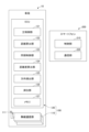
- FIG. 2 is a block diagram showing configurations of vehicle 10 and smartphone 200 equipped with positioning device 100 according to the embodiment.
- the positioning device 100 includes ten wireless communication units 110 mounted on the vehicle 10 and an ECU (Electronic Control Unit) 120 mounted on the vehicle 10 .
- Each wireless communication unit 110 has multiple antennas 111 .
- the number of antennas 111 connected to each wireless communication unit 110 may be two or more, and may be about three.
- the smartphone 200 is an example of a mobile communication unit, and its position is obtained (positioned) by the positioning device 100 when it is outside the vehicle 10 .
- Smartphone 200 has control unit 210 and communication unit 220 . The user can unlock/lock the remote key of the vehicle 10 , operate automatic parking assistance, and the like through the smartphone 200 .
- the radio communication unit 110 includes, for example, PA (Power Amplifier), LNA (Low Noise Amplifier), OM (Orthogonal Modulator), ODM (Orthogonal DeModulator), VCO (Voltage Controlled Oscillator), PLL (Phase Locked Loop), and codec processing. including departments, etc.
- PA Power Amplifier
- LNA Low Noise Amplifier
- OM Organic Modulator
- ODM Orthogonal DeModulator
- VCO Voltage Controlled Oscillator
- PLL Phase Locked Loop
- codec processing including departments, etc.
- PA Power Amplifier
- LNA Low Noise Amplifier
- OM Organic Modulator
- ODM Organic DeModulator
- VCO Voltage Controlled Oscillator
- PLL Phase Locked Loop
- codec processing including departments, etc.
- PA is connected to antenna 111 .
- the wireless communication unit 110 is controlled by the ECU 120 and communicates with Bluetooth packet
- the ECU 120 is an ECU for the positioning device 100.
- Various ECUs are mounted on the vehicle 10 in addition to the ECU 120, and are communicably connected to the ECU 120 via an in-vehicle network.
- the ECU 120 is implemented by a computer including a CPU (Central Processing Unit), RAM (Random Access Memory), ROM (Read Only Memory), internal bus, and the like.
- the ECU 120 has a main control section 121 , a distance calculation section 122 , a synchronization control section 123 , a distance difference calculation section 124 , a direction derivation section 125 , a positioning section 126 and a memory 127 .
- the main control unit 121, the distance calculation unit 122, the synchronization control unit 123, the distance difference calculation unit 124, the direction derivation unit 125, and the positioning unit 126 represent functions of the program executed by the ECU 120 as functional blocks.
- a memory 127 functionally represents the memory of the ECU 120 .
- the main control unit 121 is a processing unit that supervises control processing of the ECU 120, and includes a distance calculation unit 122, a synchronization control unit 123, a distance difference calculation unit 124, a direction derivation
- the processing other than the processing executed by the unit 125 and the positioning unit 126 is executed.
- the memory 127 stores programs and programs necessary for the main control unit 121, the distance calculation unit 122, the synchronization control unit 123, the distance difference calculation unit 124, the direction derivation unit 125, and the positioning unit 126 to execute the above-described processing. Stores data, etc.
- the ECU 120 performs synchronization processing in any of the first positioning method to the fourth positioning method. Therefore, the synchronization process will be described first, and then the first to fourth positioning methods will be described. In the description of the first positioning method to the fourth positioning method, distance calculation section 122, synchronization control section 123, distance difference calculation section 124, direction derivation section 125, and positioning section 126 will be described.
- the synchronization process is performed by the synchronization control unit 123 based on the distance calculated by the distance calculation unit 122, and corrects the clocks of the wireless communication units 110A and 110B so that they are synchronized. Clock correction is realized by the clock correction method of the embodiment.
- the clocks of the radio communication units 110A and 110B are the clocks used by the radio communication units 110A and 110B for their operation.
- the wireless communication units 110A and 110B communicate using Bluetooth packet signals. Note that in the synchronization process, any one of the plurality of antennas 111 connected to each wireless communication unit 110 may be used as the reference antenna 111 .
- the distance calculation unit 122 calculates the phase when the wireless communication unit 110B receives the packet signal of the frequency f1 transmitted from the wireless communication unit 110A and the packet signal of the frequency f2 transmitted from the wireless communication unit 110A to the wireless communication unit 110B.
- the distance L between the radio communication units 110A and 110B is obtained based on the phase when the radio communication units 110A and 110B receive the signal and the predetermined distance L0.
- the frequency f1 is an example of the first frequency
- the frequency f2 is an example of the second frequency.
- the frequencies f1 and f2 are any two of a plurality of channels included in the Bluetooth communication band, and are frequencies at which the wave number between the wireless communication units 110A and 110B is the same.
- the predetermined distance L0 is an example of a first predetermined distance, and is the distance between the wireless communication units 110A and 110B. Since the wireless communication units 110A and 110B are attached to the front and rear ends of the sides of the vehicle 10, the predetermined distance L0 is known.
- the distance calculation unit 122 obtains the distance L between the wireless communication unit 110A and the wireless communication unit 110B as follows. In obtaining the distance L, the distance calculation unit 122 causes the wireless communication unit 110A to transmit the packet signal of the frequency f1 and the packet signal of the frequency f2. Packet signals of frequencies f1 and f2 are received by the wireless communication unit 110B. Data representing the predetermined distance L0 is stored in the memory 127. FIG.
- the wave number of the packet signal of frequency f1 between the radio communication units 110A and 110B and the wave number of the packet signal of frequency f2 between the radio communication units 110A and 110B are n, and the packet signal of frequency f1 is the radio communication unit 110B is received, P2 is the phase when the wireless communication unit 110B receives the packet signal of the second frequency, ⁇ 1 is the wavelength of the packet signal of frequency f1, and ⁇ 2 is the wavelength of the packet signal of frequency f2.
- the distance calculator 122 can calculate the distance L between the wireless communication units 110A and 110B according to the following equations (1A) to (1E).
- the distance L can be expressed by the following equation (1).
- the distance L can be expressed by the following equation (2).
- the distance L can be expressed by the following equation (5).
- c is the speed of light (3 ⁇ 10 8 m/sec).
- the synchronization control unit 123 corrects the clocks of the wireless communication units 110A and 110B so that they are synchronized from the difference (L-L0) between the distance L calculated by the distance calculation unit 122 and the predetermined distance L0. If the clocks of the wireless communication units 110A and 110B are out of sync, the phases P1 and P2 increase, so the difference (L-L0) between the distance L obtained by Equation (5) and the known distance L0 increases. Become. Synchronization control section 123 corrects the phase of the clock of at least one of radio communication sections 110A and 110B so that the clocks of radio communication sections 110A and 110B are synchronized based on the distance difference (L ⁇ L0). Just do it.
- the synchronization control unit 123 can correct the clock phase with an accuracy of 1 ns (nanosecond) level. For example, if 360 degrees is analyzed at 1 MHz with a resolution of 10 bits, the phase can be analyzed at a level of 1 ns and corrected with an accuracy of a level of 1 ns.
- the relationship between the difference in distance (L ⁇ L0) and the correction amount of the phase of the clocks of the wireless communication units 110A and 110B is measured in advance, data in a table format is created, and stored in the memory 127. , the phase correction amount corresponding to the difference in distance (L ⁇ L0) is read, and the phase of the clock of either one of the wireless communication units 110A and 110B is corrected.
- the distance calculation unit 122 causes the wireless communication unit 110A to transmit packet signals of frequencies f1 and f2 and the wireless communication unit 110B receives the packet signals.
- the calculation unit 122 causes the wireless communication unit 110B to transmit packet signals of frequencies f1 and f2, and the wireless communication unit 110A receives the packet signals.
- clock phase can be corrected. In this way, by transmitting and receiving packet signals bidirectionally between the wireless communication units 110A and 110B and performing synchronization processing, phase correction is performed so that the phases of the clocks of the wireless communication units 110A and 110B match. It can be performed with higher accuracy.
- Distance difference calculation unit 124 calculates phase ⁇ 1 when wireless communication unit 110A receives a packet signal of frequency f1 transmitted from smartphone 200 in a state in which clock correction is performed by synchronization control unit 123, and phase ⁇ 1 from smartphone 200.
- Phase ⁇ 2 when wireless communication unit 110A receives a packet signal of frequency f2 transmitted phase ⁇ 3 when wireless communication unit 110B receives a signal of frequency f1 transmitted from smartphone 200, and transmission from smartphone 200 distance between distance L1 between smartphone 200 and wireless communication unit 110A and distance L2 between smartphone 200 and wireless communication unit 110B, based on phase ⁇ 4 when wireless communication unit 110B receives a signal of frequency f2, Calculate the difference.
- the packet signal of frequency f1 transmitted from the smartphone 200 is an example of the first signal
- the phase ⁇ 1 when received by the wireless communication unit 110A is an example of the first phase
- the packet signal of frequency f2 transmitted from smartphone 200 is an example of a second signal
- phase ⁇ 2 when received by wireless communication unit 110A is an example of a second phase
- the phase ⁇ 3 when the wireless communication unit 110B receives the signal of the frequency f1 transmitted from the smartphone 200 is an example of the third phase.
- the phase ⁇ 4 when the wireless communication unit 110B receives the signal of the frequency f2 transmitted from the smartphone 200 is an example of the fourth phase.
- any one of the plurality of antennas 111 connected to each wireless communication unit 110 may be used as the reference antenna 111 .
- a plurality of antennas 111 are used in a second positioning method, which will be described later.
- the distance difference calculator 124 calculates the absolute value
- c is the speed of light.
- the positioning unit 126 calculates the distance difference (
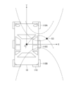
- FIG. 3 is a diagram showing two hyperbolas that satisfy Equation (7).
- Two hyperbolas are indicated by dashed lines in FIG.
- the position of smartphone 200 with respect to wireless communication units 110A and 110B is somewhere on two hyperbolic lines whose focal points are the reference points of antennas 111 of wireless communication units 110A and 110B.
- the positioning unit 126 can narrow down the position of the smartphone 200 to positions on the two hyperbolas, and can obtain an approximate position of the smartphone 200 .
- ⁇ Second positioning method> In the second positioning method, after the distance difference calculation unit 124 obtains the distance difference (
- Direction derivation unit 125 obtains the direction of arrival of the signal from smartphone 200 to wireless communication unit 110A based on the phase difference when the packet signals are received by multiple antennas 111 of wireless communication unit 110A.
- the direction of arrival of the signal from the smartphone 200 to the wireless communication unit 110B is obtained based on the phase difference when the packet signals are received by the multiple antennas of the unit 110B.
- the direction deriving unit 125 receives the packet signal from the smartphone 200 to the wireless communication unit 110A based on the phase difference when the packet signal of the frequency f1 is received by the plurality of antennas 111 of the wireless communication unit 110A. Determine the arrival direction of arrival.
- the direction derivation unit 125 may obtain the direction of arrival based on the phase difference when the packet signal of frequency f2 is received, or the direction of arrival when two packet signals of frequencies f1 and f2 are received. Two directions of arrival may be determined based on the phase difference, but here, as an example, a mode of determining the direction of arrival based on the phase difference when a packet signal of frequency f1 is received will be described.
- the arrival direction in which the packet signal arrives from the smartphone 200 to the wireless communication unit 110A is an example of the first arrival direction.
- the direction deriving unit 125 determines the arrival direction of the packet signal from the smartphone 200 to the wireless communication unit 110B based on the phase difference when the packet signals of the frequency f1 are received by the plurality of antennas 111 of the wireless communication unit 110B.
- the direction derivation unit 125 may obtain the direction of arrival based on the phase difference when the packet signal of frequency f2 is received, or the direction of arrival when two packet signals of frequencies f1 and f2 are received.
- Two directions of arrival may be determined based on the phase difference, but here, as an example, a mode of determining the direction of arrival based on the phase difference when a packet signal of frequency f1 is received will be described.
- the arrival direction in which the packet signal arrives from the smartphone 200 to the wireless communication unit 110B is an example of the second arrival direction.
- the positioning unit 126 based on the distance difference obtained by the distance difference calculation unit 124 and the two directions of arrival obtained by the direction derivation unit 125, The position of smartphone 200 with respect to wireless communication units 110A and 110B is obtained.
- FIG. 4 is a diagram showing two hyperbolas that satisfy Equation (7) and the receivable areas of the wireless communication units 110A and 110B.
- Receivable area 110A1 of wireless communication unit 110A represents an area in which wireless communication unit 110A can receive packet signals from smartphone 200 when smartphone 200 is present within receivable area 110A1.
- Receivable area 110B1 of wireless communication unit 110B represents an area in which wireless communication unit 110B can receive packet signals from smartphone 200 when smartphone 200 is present within receivable area 110B1.
- the overlapping area 110AB1 is an overlapping area between the receivable area 110A1 and the receivable area 110B1.
- arrow A represents the direction of arrival of the packet signal derived by the direction derivation unit 125 for the wireless communication unit 110A.
- An arrow B represents the direction of arrival of the packet signal derived by the direction derivation unit 125 for the wireless communication unit 110B.
- the position of smartphone 200 with respect to wireless communication units 110A and 110B is the intersection of vector A represented by arrow A and vector B represented by arrow B, and can be found as the intersection on either hyperbola. In fact, such an intersection point may not be obtained due to an error or the like. In such a case, the following should be done.
- a point of intersection may be obtained by extending vector A or B, and the point on the hyperbola closest to the intersection may be obtained as the position of smartphone 200 .
- vector A is extended to generate vector A1
- point S2 on the hyperbola closest to intersection point S11 of vector A1 and vector B is the position of smart phone 200 . Therefore, the positioning unit 126 can specify the position of the smartphone 200 at the position of the intersection S2.
- the position of smartphone 200 is measured using three wireless communication units 110A, 110B, and 110C. Further, in the third positioning method, the positioning device 100 does not derive the direction of arrival by the direction derivation unit 125 as in the second positioning method. Therefore, when the positioning device 100 executes the third positioning method without executing the second positioning method, the positioning device 100 does not need to include the direction deriving section 125 .
- the distance calculation unit 122 obtains the distance L between the wireless communication units 110A and 110B and the distance L between the wireless communication units 110A and 110C.
- the distance calculation unit 122 obtains the distance L between the wireless communication units 110A and 110B in the same manner as in the synchronization processing described above.
- the distance calculation unit 122 calculates the phase when the wireless communication unit 110C receives the packet signal of the frequency f1 transmitted from the wireless communication unit 110A and the packet signal of the frequency f2 transmitted from the wireless communication unit 110A.
- the distance L between the wireless communication units 110A and 110C is obtained based on the phase when the unit 110C receives the signal and the predetermined distance L00.
- the predetermined distance L00 is an example of a known second predetermined distance, for example, the distance between the reference points of the antennas 111 of the wireless communication unit 110A and the reference points of the antennas 111 of the wireless communication unit 110C. be.
- the method of obtaining the distance L between the radio communication units 110A and 110C is the same as the method of obtaining the distance L between the radio communication units 110A and 110B.
- the synchronization control unit 123 corrects the clocks of the wireless communication units 110A and 110B so that they are synchronized in the same manner as in the synchronization process described above, and also adjusts the distance between the wireless communication units 110A and 110C calculated by the distance calculation unit 122. Based on the difference between L and the predetermined distance L00, correction is made so that the clocks of the wireless communication units 110A and 110C are synchronized.
- the distance difference calculation unit 124 calculates the phase ⁇ 5 when the wireless communication unit 110C receives the packet signal of the frequency f1 transmitted from the smartphone 200 in a state where the clocks of the wireless communication units 110A, 110B, and 110C are corrected. and the distance between smartphone 200 and wireless communication unit 110A and the distance between smartphone 200 and wireless communication unit 110A based on phase ⁇ 6 and phases ⁇ 1 and ⁇ 2 when wireless communication unit 110C receives a packet signal of frequency f2 transmitted from smartphone 200. and the distance to the wireless communication unit 110C.
- Phase ⁇ 5 is an example of a fifth phase
- phase ⁇ 6 is an example of a sixth phase.
- Positioning unit 126 calculates the difference between the distance between smartphone 200 and wireless communication unit 110A and the distance between smartphone 200 and wireless communication unit 110B obtained by distance difference calculating unit 124, and the distance between smartphone 200 and wireless communication unit 110A. and the distance difference between the distances between smartphone 200 and wireless communication unit 110C, the position of smartphone 200 with respect to wireless communication units 110A, 110B, and 110C is obtained.
- FIG. 5 is a diagram showing four hyperbolas obtained by the third positioning method.
- broken lines indicate two hyperbolas obtained based on the distance difference between the distance between smartphone 200 and wireless communication unit 110A and the distance between smartphone 200 and wireless communication unit 110B.
- two hyperbolas obtained based on the distance difference between the distance between smartphone 200 and wireless communication unit 110A and the distance between smartphone 200 and wireless communication unit 110C are indicated by dashed-dotted lines.
- the position of the smartphone 200 with respect to the wireless communication units 110A and 110B is the intersection point S3 outside the vehicle 10 among the intersections of the two hyperbolas indicated by the dashed lines and the two hyperbolas indicated by the dashed-dotted lines.
- Positioning unit 126 can specify the position of smartphone 200 at the position of intersection S3.
- the position of smartphone 200 can be identified at intersection point S3 by the condition that it is positioned on two hyperbolic lines (dashed lines) obtained based on the distance difference obtained by combining wireless communication units 110A and 110B, and This is because the point satisfies the condition that it is located on two hyperbolas (one-dot chain lines) determined based on the distance difference obtained by the combination of 110C.
- the synchronization control unit 123 corrects the clocks of the wireless communication units 110A and 110B so as to be synchronized and corrects the clocks of the wireless communication units 110A and 110C to be synchronized. For this reason, the distance calculation unit 122 obtained the distance L between the wireless communication units 110A and 110B and the distance L between the wireless communication units 110A and 110C.
- the synchronization control unit 123 corrects the clocks of the wireless communication units 110A and 110B to synchronize, and corrects the clocks of the wireless communication units 110B and 110C to synchronize. good too. Even in this way, the clocks of the radio communication units 110A, 110B, and 110C can be corrected to be synchronized.
- the distance calculation unit 122 may obtain the distance L between the wireless communication units 110A and 110B and the distance L between the wireless communication units 110B and 110C.
- the distance difference calculation unit 124 calculates the phase ⁇ 5 when the wireless communication unit 110C receives the packet signal of the frequency f1 transmitted from the smartphone 200 in a state where the clocks of the wireless communication units 110A, 110B, and 110C are corrected. and the distance between smartphone 200 and wireless communication unit 110B, and the distance between smartphone 200 and wireless communication unit 110B based on phase ⁇ 6 and phases ⁇ 3 and ⁇ 4 when wireless communication unit 110C receives a packet signal of frequency f2 transmitted from smartphone 200. and the distance to the wireless communication unit 110C.
- Positioning unit 126 is positioned on two hyperbolic lines determined based on the distance difference obtained by combining radio communication units 110A and 110B, and based on the distance difference obtained by combining radio communication units 110B and 110C.
- the positions of smartphone 200 with respect to wireless communication units 110A, 110B, and 110C may be obtained as points that satisfy the condition that the points are located on the two hyperbolas to be obtained.
- ⁇ Fourth positioning method> Under the condition that the clocks of the wireless communication units 110A and 110B are synchronized by correcting the clocks by the synchronization control unit 123, the distance difference between the times t1 and t2 and the distances L1 and L2 , the absolute value of
- is calculated by the distance difference calculator 124 according to Equation (6) as described in the first positioning method.
- main control unit 121 uses times t1 and t2 and speed of light c to determine the distance between smartphone 200 and wireless communication unit 110A and the distance between smartphone 200 and wireless communication unit 110B.
- a distance difference ⁇ L from the distance is obtained.
- the distance difference ⁇ L can be expressed by the following equation (8). Note that the difference (t1-t2) between the times t1 and t2 is an example of the difference between the first time and the second time.
- of the distance difference calculated by the distance difference calculation unit 124 is calculated using the phases ⁇ 1 and ⁇ 2, whereas the main control unit 121 uses the times t1 and t2 and the speed of light c. is calculated based on the times t1 and t2 and the speed of light c. It can be used as an evaluation criterion.
- the main control unit 121 uses the distance difference ⁇ L to evaluate the absolute value of the distance difference
- a quality factor Q representing the accuracy (quality) of the distance difference L1-L2 is used for the evaluation.
- the quality factor Q can be expressed by the following equation (9) using the absolute value
- the main control unit 121 evaluates the quality of the distance difference L1-L2 based on the difference between the times t1 and t2 and the distance difference L1-L2 calculated by the distance difference calculation unit 124 according to Equation (9).
- of the distance difference calculated by the distance difference calculator 124 can be calculated.
- the quality factor Q is, for example, when evaluating the distance difference L1-L2 calculated by the distance difference calculation unit 124 when obtaining the position of the smartphone 200 by the first positioning method, the second positioning method, and the third positioning method. available for
- the synchronization control unit 123 determines that the clocks of the wireless communication units 110 are synchronized from the difference (L ⁇ L0) between the distance L calculated by the distance calculation unit 122 and the predetermined distance L0.
- the phase of the clock of the wireless communication unit 110 is corrected so that the The clock phase can be corrected with an accuracy of 1 ns (nanosecond) level.
- the positioning device 100 capable of correcting the phases of the clocks between the wireless communication units 110 with high precision.
- the distance calculation unit 122 can reliably and easily obtain the distance L between the wireless communication units 110 according to formulas (1) to (5). Since the phase of the clock of the wireless communication unit 110 is corrected based on the difference (L-L0) between the distance L and the predetermined distance L0, the phase of the clock can be reliably and easily corrected with an accuracy of 1 ns (nanosecond) level. can do.
- the positioning unit 126 is positioned on two hyperbolic lines (hyperbolic lines for the radio communication units 110A and 110B) represented by the distance difference (
- the position of smartphone 200 can be narrowed down, and the approximate position of smartphone 200 can be obtained.
- Two hyperbolas are obtained by TOA positioning using wireless communication units 110A and 110B. Therefore, it is possible to provide the positioning device 100 that can accurately correct the phase of the clocks between the wireless communication units 110 and obtain the approximate position of the smartphone 200 by TOA.
- the positioning unit 126 uses two hyperbolic lines (hyperbolic lines for the wireless communication units 110A and 110B) representing the distance difference obtained by the distance difference calculating unit 124, , and the direction of arrival of the packet signal derived for 110B can be identified as the position of smartphone 200 .
- the two hyperbolas are obtained by TOA positioning using radio communication units 110A and 110B, and the direction of arrival is obtained by angle detection by AOA using radio communication units 110A and 110B. Therefore, it is possible to provide the positioning device 100 capable of specifying the position of the smartphone 200 by correcting the phases of the clocks between the wireless communication units 110 with high precision and combining TOA and AOA.
- two hyperbolic lines are obtained based on the distance difference between the smartphone 200 and the wireless communication units 110A and 110B, and the distance difference between the smartphone 200 and the wireless communication units 110A and 110C.
- a point of intersection with two hyperbolas can be specified as the position of smartphone 200 .
- Four hyperbolas are obtained by TOA positioning using radio communication units 110A and 110B and by TOA positioning using radio communication units 110A and 110C. Therefore, it is possible to provide the positioning device 100 that can accurately correct the phases of the clocks between the wireless communication units 110 and specify the position of the smartphone 200 by positioning with the TOA.
- Two hyperbolas determined based on the distance difference between smartphone 200 and wireless communication units 110A and 110B, and two hyperbolas determined based on the distance difference between smartphone 200 and wireless communication units 110B and 110C. can be identified as the position of smartphone 200 .
Landscapes
- Engineering & Computer Science (AREA)
- Computer Networks & Wireless Communication (AREA)
- Signal Processing (AREA)
- Physics & Mathematics (AREA)
- General Physics & Mathematics (AREA)
- Radar, Positioning & Navigation (AREA)
- Remote Sensing (AREA)
- Position Fixing By Use Of Radio Waves (AREA)
Abstract
無線通信装置同士のクロックの位相を高精度に補正可能な測位装置、及び、クロック補正方法を提供する。 測位装置は、移動通信部の位置を測位する測位装置であって、第1無線通信部と、前記第1無線通信部から既知の第1所定距離の位置に配置される第2無線通信部と、前記第1無線通信部から送信される第1周波数の信号を前記第2無線通信部が受信したときの位相と、前記第1無線通信部から送信される第2周波数の信号を前記第2無線通信部が受信したときの位相と、前記第1所定距離とに基づいて前記第1無線通信部及び前記第2無線通信部の間の距離を求める距離算出部と、前記距離算出部によって算出される距離と、前記第1所定距離との差から、前記第1無線通信部及び前記第2無線通信部の同期を行う、同期調整部とを含む。
Description
本開示は、測位装置、及び、クロック補正方法に関する。
従来より、無線基地局間を同期させるための同期信号を供給する親装置と、第1チャネル及び第2チャネルを有する伝送路を介して前記親装置と接続される子装置とを備える時刻同期システムがある。前記子装置は、GPS(Global Positioning System)の基準信号を受信するGPS受信部と、前記親装置への上り信号の第1チャネルに前記基準信号を多重する多重部と、前記上り信号を前記伝送路を介して送信する送信部とを具備する。前記親装置は、前記子装置への下り信号の第2チャネルに遅延測定信号を多重する多重部と、前記下り信号を前記伝送路を介して送信する送信部と、前記子装置からの上り信号から第1チャネル及び第2チャネルを分離する分離部と、前記第2チャネルの遅延測定信号に基づいて前記伝送路の遅延時間を測定する遅延測定部と、前記遅延時間をもとに前記第1チャネルの基準信号の位相を補正する第1位相補正部と、前記第1位相補正部で補正された基準信号に基づいて前記第1同期信号を出力する出力部とを具備する(例えば、特許文献1参照)。
GPSの信号は、反射によるマルチパス等の通信環境等の影響を受けやすいため、GPSの信号を用いてGPSの基準信号の位相を補正する方法では、補正の精度に限界がある。
ところで、無線通信装置同士でTOA(Time Of Arrival)を用いて測位を行う場合に、RTT(Round Trip Time)を計測する場合には、無線通信装置同士のクロックの位相に1ns(ナノ秒)レベルの精度が求められる。
そこで、無線通信装置同士のクロックの位相を高精度に補正可能な測位装置、及び、クロック補正方法を提供することを目的とする。
本開示の実施形態の測位装置は、移動通信部の位置を測位する測位装置であって、第1無線通信部と、前記第1無線通信部から既知の第1所定距離の位置に配置される第2無線通信部と、前記第1無線通信部から送信される第1周波数の信号を前記第2無線通信部が受信したときの位相と、前記第1無線通信部から送信される第2周波数の信号を前記第2無線通信部が受信したときの位相と、前記第1所定距離とに基づいて前記第1無線通信部及び前記第2無線通信部の間の距離を求める距離算出部と、前記距離算出部によって算出される距離と、前記第1所定距離との差から、前記第1無線通信部及び前記第2無線通信部の同期を行う、同期調整部とを含む。
無線通信装置同士のクロックの位相を高精度に補正可能な測位装置、及び、クロック補正方法を提供することができる。
以下、本開示の測位装置、及び、クロック補正方法を適用した実施形態について説明する。
<実施形態>
図1は、実施形態の測位装置を搭載した車両10を示す図である。図1には、車両10の平面視における中心を原点OとしたXY座標系を示す。車両10のボディの四隅には、複数の無線通信部110が配置されている。無線通信部110は、無線通信装置の一例である。図1では、一例として10個の無線通信部110を示す。車両10の前方の左右端部には無線通信部110が1つずつ設けられ、車両10の後方の左右端部には無線通信部110が1つずつ設けられている。また、車両10の左側方の前後端部と前後方向の真ん中とに無線通信部110が1つずつ設けられ、車両10の右側方の前後端部と前後方向の真ん中とに無線通信部110が1つずつ設けられている。
図1は、実施形態の測位装置を搭載した車両10を示す図である。図1には、車両10の平面視における中心を原点OとしたXY座標系を示す。車両10のボディの四隅には、複数の無線通信部110が配置されている。無線通信部110は、無線通信装置の一例である。図1では、一例として10個の無線通信部110を示す。車両10の前方の左右端部には無線通信部110が1つずつ設けられ、車両10の後方の左右端部には無線通信部110が1つずつ設けられている。また、車両10の左側方の前後端部と前後方向の真ん中とに無線通信部110が1つずつ設けられ、車両10の右側方の前後端部と前後方向の真ん中とに無線通信部110が1つずつ設けられている。
10個の無線通信部110のうちのいずれか1つは第1無線通信部の一例であり、他のいずれか1つは第2無線通信部の一例であり、さらに他のいずれか1つは第3無線通信部の一例である。
ここでは、一例として、車両10の右側方の前端部に設けられる無線通信部110を無線通信部110Aとして区別し、車両10の右側方の後端部に設けられる無線通信部110を無線通信部110Bとして区別し、車両10の右側方の前後方向の真ん中に設けられる無線通信部110を無線通信部110Cとして区別する。無線通信部110Aは第1無線通信部の一例であり、無線通信部110Bは第2無線通信部の一例であり、無線通信部110Cは第3無線通信部の一例である。
10個の無線通信部110が動作に利用するクロックの周波数は、すべて等しい。各無線通信部110は、スマートフォン200との間でデータを送信又は受信するための無線通信部であり、一例としてBluetooth(登録商標)規格の近距離無線通信器である。各無線通信部110は複数のアンテナを有する。なお、ここでは無線通信部110がBluetooth規格の近距離無線通信器である形態について説明するが、WLAN(Wireless Local Area Network)やその他の規格の通信を行う機器であってもよい。
図2は、実施の形態の測位装置100を搭載した車両10とスマートフォン200の構成を示すブロック図である。測位装置100は、車両10に搭載される10個の無線通信部110と、車両10に搭載されるECU(Electronic Control Unit:電子制御装置)120とを含む。各無線通信部110は、複数のアンテナ111を有する。各無線通信部110に接続されるアンテナ111の数は、2以上であればよく、3つ程度であってもよい。
スマートフォン200は、移動通信部の一例であり、車両10の外にあるときに測位装置100によって位置が求められる(測位される)。スマートフォン200は、制御部210及び通信部220を有する。利用者は、スマートフォン200を通じて、車両10のリモートキーの解錠/施錠、自動駐車支援の操作等を行うことができる。
無線通信部110は、例えば、PA(Power Amplifier)、LNA(Low Noise Amplifier)、OM(Orthogonal Modulator)、ODM(Orthogonal DeModulator)、VCO(Voltage Controlled Oscillator)、PLL(Phase Locked Loop)、及びコーデック処理部等を含む。PAはアンテナ111に接続されている。無線通信部110は、ECU120によって制御され、測距のためにBluetoothのパケット信号で通信する。
ECU120は、測位装置100用のECUである。車両10にはECU120以外にも種々のECUが搭載されており、ECU120と車載ネットワークを介して通信可能に接続されている。
ECU120は、CPU(Central Processing Unit)、RAM(Random Access Memory)、ROM(Read Only Memory)、及び内部バス等を含むコンピュータによって実現される。ECU120は、主制御部121、距離算出部122、同期制御部123、距離差算出部124、方向導出部125、測位部126、及びメモリ127を有する。主制御部121、距離算出部122、同期制御部123、距離差算出部124、方向導出部125、測位部126は、ECU120が実行するプログラムの機能(ファンクション)を機能ブロックとして示したものである。また、メモリ127は、ECU120のメモリを機能的に表したものである。
以下では、ECU120が実行可能な第1測位方法から第4測位方法について説明する。第1測位方法から第4測位方法のいずれにおいても、主制御部121は、ECU120の制御処理を統括する処理部であり、距離算出部122、同期制御部123、距離差算出部124、方向導出部125、測位部126が実行する処理以外の処理を実行する。
また、メモリ127は、主制御部121、距離算出部122、同期制御部123、距離差算出部124、方向導出部125、測位部126が上述のような処理を実行するために必要なプログラムやデータ等を格納する。
また、第1測位方法から第4測位方法のいずれにおいても、ECU120は、同期処理を行う。このため、まず同期処理について説明し、その後に第1測位方法から第4測位方法について説明する。第1測位方法から第4測位方法の説明では、距離算出部122、同期制御部123、距離差算出部124、方向導出部125、測位部126について説明する。
<同期処理>
同期処理は、同期制御部123が、距離算出部122によって算出される距離に基づいて行う処理であり、無線通信部110A及び110Bのクロックが同期するように補正する。クロックの補正は、実施形態のクロック補正方法によって実現される。無線通信部110A及び110Bのクロックは、無線通信部110A及び110Bが動作に利用するクロックである。無線通信部110A及び110Bは、Bluetoothのパケット信号で通信する。なお、同期処理では、各無線通信部110に接続される複数のアンテナ111のうちのいずれか1つを基準のアンテナ111として用いればよい。
同期処理は、同期制御部123が、距離算出部122によって算出される距離に基づいて行う処理であり、無線通信部110A及び110Bのクロックが同期するように補正する。クロックの補正は、実施形態のクロック補正方法によって実現される。無線通信部110A及び110Bのクロックは、無線通信部110A及び110Bが動作に利用するクロックである。無線通信部110A及び110Bは、Bluetoothのパケット信号で通信する。なお、同期処理では、各無線通信部110に接続される複数のアンテナ111のうちのいずれか1つを基準のアンテナ111として用いればよい。
距離算出部122は、無線通信部110Aから送信される周波数f1のパケット信号を無線通信部110Bが受信したときの位相と、無線通信部110Aから送信される周波数f2のパケット信号を無線通信部110Bが受信したときの位相と、所定距離L0とに基づいて無線通信部110A及び110Bの間の距離Lを求める。ここで、周波数f1は第1周波数の一例であり、周波数f2は第2周波数の一例である。周波数f1、f2は、Bluetoothの通信帯域に含まれる複数のチャンネルのうちのいずれか2つであり、無線通信部110A及び110Bの間における波数が同一になる周波数である。所定距離L0は第1所定距離の一例であり、無線通信部110A及び110Bの間の距離である。無線通信部110A及び110Bは、車両10の側部の前後端部に取り付けられているため、所定距離L0は既知である。
より具体的には、距離算出部122は、次のようにして無線通信部110A及び無線通信部110Bの間の距離Lを求める。距離Lを求めるにあたり、距離算出部122は、無線通信部110Aに周波数f1のパケット信号と周波数f2のパケット信号とを送信させる。周波数f1及びf2のパケット信号は無線通信部110Bによって受信される。なお、所定距離L0を表すデータは、メモリ127に格納されている。
ここで、無線通信部110A及び110Bの間における周波数f1のパケット信号の波数と、無線通信部110A及び110Bの間における周波数f2のパケット信号の波数とをn、周波数f1のパケット信号を無線通信部110Bが受信したときの位相をP1、第2周波数のパケット信号を無線通信部110Bが受信したときの位相をP2、周波数f1のパケット信号の波長をλ1、周波数f2のパケット信号の波長をλ2とすると、距離算出部122は、次式(1A)~(1E)に従って無線通信部110A及び110Bの間の距離Lを求めることができる。
具体的には、周波数f1のパケット信号についての波数n、位相P1、波長λ1を用いると、距離Lは次式(1)で表すことができる。

同様に、周波数f2のパケット信号についての波数n、位相P2、波長λ2を用いると、距離Lは次式(2)で表すことができる。

式(1)より次式(3)が得られる。

同様に式(2)より次式(4)が得られる。

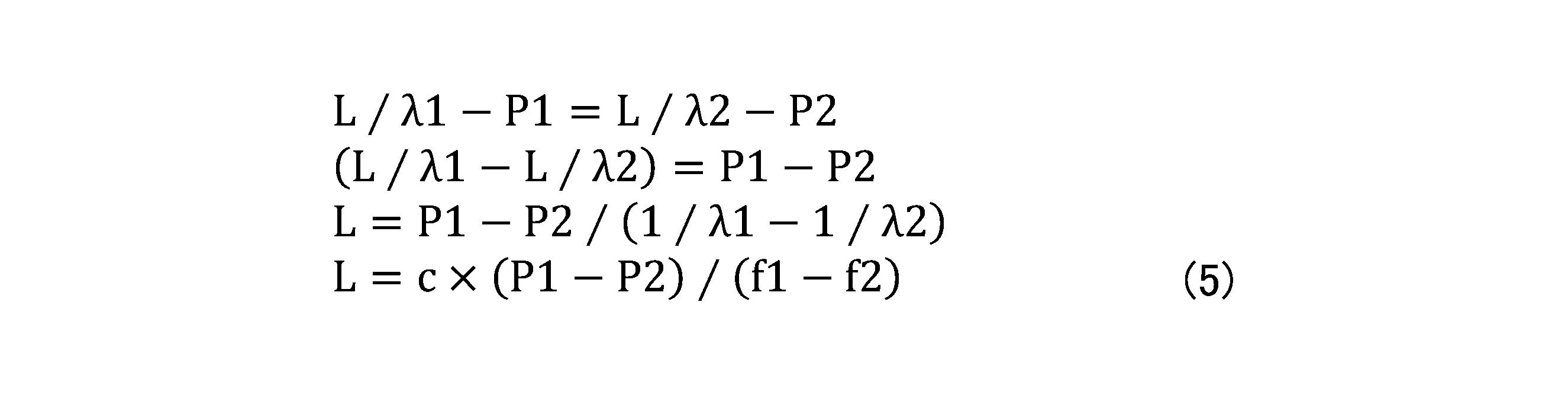
式(3)、(4)から波数nを消去し、次に示すように変形して行くと、距離Lは次式(5)で表すことができる。ただし、cは光速(3×10⁸m/sec)である。
同期制御部123は、距離算出部122によって算出される距離Lと、所定距離L0との差(L-L0)から、無線通信部110A及び110Bのクロックが同期するように補正する。無線通信部110A及び110Bのクロックがずれていると、位相P1、P2が大きくなるため、式(5)で求まる距離Lと既知の距離である所定距離L0との差(L-L0)が大きくなる。同期制御部123は、距離の差(L-L0)に基づいて、無線通信部110A及び110Bのクロックが同期するように、無線通信部110A及び110Bのうちの少なくとも一方のクロックの位相を補正すればよい。同期制御部123は、クロックの位相を1ns(ナノ秒)レベルの精度で補正することができる。例えば、360度を1MHzで10ビットの分解能で解析すれば、位相を1nsのレベルで解析可能であり、1nsレベルの精度で補正することができる。
また、例えば、距離の差(L-L0)と、無線通信部110A及び110Bのクロックの位相の補正量との関係を予め測定してテーブル形式のデータを作成してメモリ127に格納しておき、距離の差(L-L0)に応じた位相の補正量を読み出して、無線通信部110A及び110Bのうちのいずれか一方のクロックの位相を補正すればよい。
なお、ここでは、一例として、距離算出部122が無線通信部110Aに周波数f1及びf2のパケット信号を送信させて、無線通信部110Bが受信する場合について説明したが、これとは逆に、距離算出部122が無線通信部110Bに周波数f1及びf2のパケット信号を送信させて、無線通信部110Aが受信することにより、無線通信部110Bから送信したパケット信号に基づいて、無線通信部110A及び110Bのクロックの位相を補正することができる。このように、無線通信部110A及び110Bの間で双方向にパケット信号の送受信を行って同期処理を行うことにより、無線通信部110A及び110Bのクロックの位相が一致するように、位相の補正をより高精度に行うことができる。
<第1測位方法>
距離差算出部124は、同期制御部123によるクロックの補正が行われた状態において、スマートフォン200から送信される周波数f1のパケット信号を無線通信部110Aが受信するときの位相α1と、スマートフォン200から送信される周波数f2のパケット信号を無線通信部110Aが受信するときの位相α2と、スマートフォン200から送信される周波数f1の信号を無線通信部110Bが受信するときの位相α3と、スマートフォン200から送信される周波数f2の信号を無線通信部110Bが受信するときの位相α4とに基づいて、スマートフォン200と無線通信部110Aとの距離L1と、スマートフォン200と無線通信部110Bとの距離L2との距離差を算出する。
距離差算出部124は、同期制御部123によるクロックの補正が行われた状態において、スマートフォン200から送信される周波数f1のパケット信号を無線通信部110Aが受信するときの位相α1と、スマートフォン200から送信される周波数f2のパケット信号を無線通信部110Aが受信するときの位相α2と、スマートフォン200から送信される周波数f1の信号を無線通信部110Bが受信するときの位相α3と、スマートフォン200から送信される周波数f2の信号を無線通信部110Bが受信するときの位相α4とに基づいて、スマートフォン200と無線通信部110Aとの距離L1と、スマートフォン200と無線通信部110Bとの距離L2との距離差を算出する。
ここで、スマートフォン200から送信される周波数f1のパケット信号は、第1信号の一例であり、無線通信部110Aが受信するときの位相α1は、第1位相の一例である。スマートフォン200から送信される周波数f2のパケット信号は、第2信号の一例であり、無線通信部110Aが受信するときの位相α2は、第2位相の一例である。スマートフォン200から送信される周波数f1の信号を無線通信部110Bが受信するときの位相α3は、第3位相の一例である。スマートフォン200から送信される周波数f2の信号を無線通信部110Bが受信するときの位相α4は、第4位相の一例である。なお、第1測位方法では、各無線通信部110に接続される複数のアンテナ111のうちのいずれか1つを基準のアンテナ111として用いればよい。複数のアンテナ111は、後述する第2測位方法において用いるが、測位装置100が第2測位方法を行わない場合には、各無線通信部110はアンテナ111を1つ有していればよい。
距離L1と距離L2との距離差の絶対値|L1-L2|を次式(6)のように表すことができる。

距離差算出部124は、式(6)から波数nを消去することにより、絶対値|L1-L2|を次式(7)のように算出する。ただし、cは光速である。

このように距離差算出部124が距離L1と距離L2との距離差(|L1-L2|)を求めると、測位部126は、距離差算出部124によって求められる距離差(|L1-L2|)に基づいて、無線通信部110A及び110Bに対するスマートフォン200の位置を求める。
図3は、式(7)を満たす2本の双曲線を示す図である。図3には、2本の双曲線を破線で示す。無線通信部110A及び110Bに対するスマートフォン200の位置は、無線通信部110A及び110Bのアンテナ111の基準点を焦点とする2本の双曲線上のどこかにあることになる。測位部126は、スマートフォン200の位置を2本の双曲線上の位置に絞ることができ、スマートフォン200の大凡の位置を求めることができる。
<第2測位方法>
第2測位方法では、距離差算出部124が第1測位方法によって式(7)で表される距離差(|L1-L2|)を求めた上で、方向導出部125がスマートフォン200から無線通信部110A及び110Bにパケット信号が到来する到来方向を求め、2本の双曲線と到来方向とに基づいて、無線通信部110A及び110Bに対するスマートフォン200の位置を求める。
第2測位方法では、距離差算出部124が第1測位方法によって式(7)で表される距離差(|L1-L2|)を求めた上で、方向導出部125がスマートフォン200から無線通信部110A及び110Bにパケット信号が到来する到来方向を求め、2本の双曲線と到来方向とに基づいて、無線通信部110A及び110Bに対するスマートフォン200の位置を求める。
方向導出部125は、無線通信部110Aの複数のアンテナ111でパケット信号が受信される際の位相差に基づいて、スマートフォン200から無線通信部110Aに信号が到来する到来方向を求めるともに、無線通信部110Bの複数のアンテナでパケット信号が受信される際の位相差に基づいて、スマートフォン200から無線通信部110Bに信号が到来する到来方向を求める。
より具体的には、方向導出部125は、無線通信部110Aの複数のアンテナ111で周波数f1のパケット信号が受信される際の位相差に基づいて、スマートフォン200から無線通信部110Aにパケット信号が到来する到来方向を求める。ここで、方向導出部125は、周波数f2のパケット信号が受信される際の位相差に基づいて到来方向を求めてもよいし、周波数f1及びf2の2つのパケット信号が受信される際の位相差に基づいて2つの到来方向を求めてもよいが、ここでは、一例として周波数f1のパケット信号が受信される際の位相差に基づいて到来方向を求める形態について説明する。スマートフォン200から無線通信部110Aにパケット信号が到来する到来方向は、第1到来方向の一例である。
また、方向導出部125は、無線通信部110Bの複数のアンテナ111で周波数f1のパケット信号が受信される際の位相差に基づいて、スマートフォン200から無線通信部110Bにパケット信号が到来する到来方向を求める。ここで、方向導出部125は、周波数f2のパケット信号が受信される際の位相差に基づいて到来方向を求めてもよいし、周波数f1及びf2の2つのパケット信号が受信される際の位相差に基づいて2つの到来方向を求めてもよいが、ここでは、一例として周波数f1のパケット信号が受信される際の位相差に基づいて到来方向を求める形態について説明する。スマートフォン200から無線通信部110Bにパケット信号が到来する到来方向は、第2到来方向の一例である。
このようにして方向導出部125が2つの到来方向を求めると、測位部126は、距離差算出部124によって求められる距離差と、方向導出部125によって求められる2つの到来方向とに基づいて、無線通信部110A及び110Bに対するスマートフォン200の位置を求める。
図4は、式(7)を満たす2本の双曲線と、無線通信部110A及び110Bの受信可能領域とを示す図である。無線通信部110Aの受信可能領域110A1は、スマートフォン200が受信可能領域110A1内に存在する場合に、無線通信部110Aがスマートフォン200からパケット信号を受信可能な領域を表す。無線通信部110Bの受信可能領域110B1は、スマートフォン200が受信可能領域110B1内に存在する場合に、無線通信部110Bがスマートフォン200からパケット信号を受信可能な領域を表す。重複領域110AB1は、受信可能領域110A1と受信可能領域110B1との重複領域である。
また、図4において、矢印Aは、方向導出部125が無線通信部110Aについて導出したパケット信号の到来方向を表す。矢印Bは、方向導出部125が無線通信部110Bについて導出したパケット信号の到来方向を表す。
無線通信部110A及び110Bに対するスマートフォン200の位置は、矢印Aによって表されるベクトルAと、矢印Bによって表されるベクトルBとの交点であって、いずれかの双曲線上に位置する交点として求まるが、実際には誤差等によって、このような交点が求まらない場合がある。そのような場合には、次のようにすればよい。ベクトルA又はBを延長して交点を求め、交点に最も近い双曲線上の点をスマートフォン200の位置として求めればよい。図4の場合には、ベクトルAを延長してベクトルA1を生成し、ベクトルA1とベクトルBの交点S11を最も近い双曲線上の点S2をスマートフォン200の位置にすればよい。このため、測位部126は、スマートフォン200の位置を交点S2の位置に特定することができる。
<第3測位方法>
第3測位方法では、3つの無線通信部110A、110B、110Cを用いてスマートフォン200の位置を測位する。また、第3測位方法では、測位装置100は、第2測位方法のように方向導出部125で到来方向を導出することを行わない。このため、測位装置100が第2測位方法を実行せずに第3測位方法を実行する場合には、測位装置100は方向導出部125を含まなくてもよい。
第3測位方法では、3つの無線通信部110A、110B、110Cを用いてスマートフォン200の位置を測位する。また、第3測位方法では、測位装置100は、第2測位方法のように方向導出部125で到来方向を導出することを行わない。このため、測位装置100が第2測位方法を実行せずに第3測位方法を実行する場合には、測位装置100は方向導出部125を含まなくてもよい。
前提として、距離算出部122は、無線通信部110A及び110Bの間の距離Lを求めるとともに、無線通信部110A及び110Cの間の距離Lを求める。距離算出部122は、無線通信部110A及び110Bの間の距離Lについては、上述した同期処理と同様に求める。
また、距離算出部122は、無線通信部110Aから送信される周波数f1のパケット信号を無線通信部110Cが受信したときの位相と、無線通信部110Aから送信される周波数f2のパケット信号を無線通信部110Cが受信したときの位相と、所定距離L00とに基づいて無線通信部110A及び110Cの間の距離Lを求める。所定距離L00は、既知の第2所定距離の一例であり、例えば、無線通信部110Aの複数のアンテナ111の基準点と、無線通信部110Cの複数のアンテナ111の基準点との間の距離である。無線通信部110A及び110Cの間の距離Lの求め方は、無線通信部110A及び110Bの間の距離Lの求め方と同様である。
また、同期制御部123は、上述した同期処理と同様に無線通信部110A及び110Bのクロックが同期するように補正するとともに、距離算出部122によって算出される無線通信部110A及び110Cの間の距離Lと、所定距離L00との差から、無線通信部110A及び110Cのクロックが同期するように補正する。
距離差算出部124は、無線通信部110A、110B、及び110Cのクロックの補正が行われた状態において、スマートフォン200から送信される周波数f1のパケット信号を無線通信部110Cが受信するときの位相α5と、スマートフォン200から送信される周波数f2のパケット信号を無線通信部110Cが受信するときの位相α6と、位相α1及びα2とに基づいて、スマートフォン200と無線通信部110Aとの距離と、スマートフォン200と無線通信部110Cとの距離との距離差を算出する。位相α5は第5位相の一例であり、位相α6は第6位相の一例である。
測位部126は、距離差算出部124によって求められる、スマートフォン200と無線通信部110Aとの距離と、スマートフォン200と無線通信部110Bとの距離との距離差と、スマートフォン200と無線通信部110Aとの距離と、スマートフォン200と無線通信部110Cとの距離との距離差とに基づいて、無線通信部110A、110B、及び110Cに対するスマートフォン200の位置を求める。
第3測位方法では、スマートフォン200と無線通信部110Aとの距離と、スマートフォン200と無線通信部110Bとの距離との距離差に基づいて図3に示すような2本の双曲線が求まり、スマートフォン200と無線通信部110Aとの距離と、スマートフォン200と無線通信部110Cとの距離との距離差に基づいて同様に2本の双曲線が求まる。すなわち、第3測位方法では、4本の双曲線が求まる。
図5は、第3測位方法で求まる4本の双曲線を示す図である。図5には、図3と同様に、スマートフォン200と無線通信部110Aとの距離と、スマートフォン200と無線通信部110Bとの距離との距離差に基づいて求まる2本の双曲線を破線で示す。また、スマートフォン200と無線通信部110Aとの距離と、スマートフォン200と無線通信部110Cとの距離との距離差に基づいて求まる2本の双曲線を一点鎖線で示す。
無線通信部110A及び110Bに対するスマートフォン200の位置は、破線で示す2本の双曲線と、一点鎖線で示す2本の双曲線との交点のうち、車両10の外側にある交点S3である。測位部126は、スマートフォン200の位置を交点S3の位置に特定することができる。スマートフォン200の位置を交点S3に特定できるのは、無線通信部110A及び110Bの組み合わせで得られる距離差に基づいて求まる2本の双曲線(破線)上に位置するという条件と、無線通信部110A及び110Cの組み合わせで得られる距離差に基づいて求まる2本の双曲線(一点鎖線)上に位置するという条件とを満たす点であるからである。
<第3測位方法の変形例>
第3測位方法では、同期制御部123は、無線通信部110A及び110Bのクロックが同期するように補正するとともに、無線通信部110A及び110Cのクロックが同期するように補正する形態について説明した。このために、距離算出部122は、無線通信部110A及び110Bの間の距離Lを求めるとともに、無線通信部110A及び110Cの間の距離Lを求めた。
第3測位方法では、同期制御部123は、無線通信部110A及び110Bのクロックが同期するように補正するとともに、無線通信部110A及び110Cのクロックが同期するように補正する形態について説明した。このために、距離算出部122は、無線通信部110A及び110Bの間の距離Lを求めるとともに、無線通信部110A及び110Cの間の距離Lを求めた。
しかしながら、第3測位方法の変形例では、同期制御部123は、無線通信部110A及び110Bのクロックが同期するように補正するとともに、無線通信部110B及び110Cのクロックが同期するように補正してもよい。このようにしても、無線通信部110A、110B、及び110Cのクロックが同期するように補正することができる。この場合には、距離算出部122は、無線通信部110A及び110Bの間の距離Lを求めるとともに、無線通信部110B及び110Cの間の距離Lを求めればよい。
距離差算出部124は、無線通信部110A、110B、及び110Cのクロックの補正が行われた状態において、スマートフォン200から送信される周波数f1のパケット信号を無線通信部110Cが受信するときの位相α5と、スマートフォン200から送信される周波数f2のパケット信号を無線通信部110Cが受信するときの位相α6と、位相α3及びα4とに基づいて、スマートフォン200と無線通信部110Bとの距離と、スマートフォン200と無線通信部110Cとの距離との距離差を算出すればよい。
測位部126は、無線通信部110A及び110Bの組み合わせで得られる距離差に基づいて求まる2本の双曲線上に位置するという条件と、無線通信部110B及び110Cの組み合わせで得られる距離差に基づいて求まる2本の双曲線上に位置するという条件とを満たす点を無線通信部110A、110B、及び110Cに対するスマートフォン200の位置として求めればよい。
<第4測位方法>
第4測位方法では、同期制御部123によるクロックの補正が行われて無線通信部110A及び110Bのクロックが同期しているという条件の下で、時刻t1、t2と、距離L1及びL2の距離差の絶対値|L1-L2|を求める。時刻t1、t2、それぞれ、無線通信部110A及び110Bがパケット信号を受信した時刻であり、それぞれ第1時刻、第2時刻の一例である。距離差の絶対値|L1-L2|は、第1測位方法で説明したように距離差算出部124によって式(6)に従って算出される。
第4測位方法では、同期制御部123によるクロックの補正が行われて無線通信部110A及び110Bのクロックが同期しているという条件の下で、時刻t1、t2と、距離L1及びL2の距離差の絶対値|L1-L2|を求める。時刻t1、t2、それぞれ、無線通信部110A及び110Bがパケット信号を受信した時刻であり、それぞれ第1時刻、第2時刻の一例である。距離差の絶対値|L1-L2|は、第1測位方法で説明したように距離差算出部124によって式(6)に従って算出される。
第4測位方法では、主制御部121は、時刻t1、t2と、光速cとを用いて、スマートフォン200と無線通信部110Aとの間の距離と、スマートフォン200と無線通信部110Bとの間の距離との距離差ΔLを求める。距離差ΔLは、次式(8)のように表すことができる。なお、時刻t1、t2の差(t1-t2)は、第1時刻及び第2時刻の差の一例である。

距離差算出部124が算出する距離差の絶対値|L1-L2|は、位相α1、α2を用いて算出されるのに対して、主制御部121が時刻t1、t2と光速cとを用いて算出する距離差ΔLは、時刻t1、t2及び光速cに基づいて算出されるため、距離差の絶対値|L1-L2|よりも精度が高く、距離差の絶対値|L1-L2|の評価基準として利用可能である。
このため、主制御部121は、距離差ΔLを用いて距離差の絶対値|L1-L2|を評価する。評価には距離差L1-L2の精度(品質)を表す品質係数Qを用いる。品質係数Qは、距離差ΔLの絶対値|ΔL|を用いて次式(9)で表すことができる。

主制御部121は、式(9)に従って時刻t1、t2の差と、距離差算出部124によって算出される距離差L1-L2とに基づいて、距離差L1-L2の品質を評価する。第4測位方法によれば、距離差算出部124が算出する距離差の絶対値|L1-L2|の品質を評価する品質係数Qを算出することができる。品質係数Qは、例えば、第1測位方法、第2測位方法、及び第3測位方法でスマートフォン200の位置を求める際に、距離差算出部124によって算出される距離差L1-L2を評価する際に利用可能である。
以上のように、測位装置100では、同期制御部123は、距離算出部122によって算出される距離Lと、所定距離L0との差(L-L0)から、無線通信部110同士のクロックが同期するように、無線通信部110のクロックの位相を補正する。クロックの位相を1ns(ナノ秒)レベルの精度で補正することができる。
したがって、無線通信部110同士のクロックの位相を高精度に補正可能な測位装置100を提供することができる。
また、距離算出部122は、式(1)~(5)に従って無線通信部110同士の間の距離Lを確実かつ容易に求めることができ、同期制御部123は、距離算出部122によって算出される距離Lと、所定距離L0との差(L-L0)に基づいて無線通信部110のクロックの位相を補正するので、確実かつ容易にクロックの位相を1ns(ナノ秒)レベルの精度で補正することができる。
また、第1案では、測位部126は、距離差算出部124によって求められる距離差(|L1-L2|)が表す2本の双曲線(無線通信部110A及び110Bについての双曲線)上の位置にスマートフォン200の位置を絞ることができ、スマートフォン200の大凡の位置を求めることができる。2本の双曲線は、無線通信部110A及び110Bを用いたTOAでの測位によって得られる。したがって、無線通信部110同士のクロックの位相を高精度に補正し、TOAによってスマートフォン200の大凡の位置を求めることができる測位装置100を提供することができる。
また、第2案では、測位部126は、距離差算出部124によって求められる距離差が表す2本の双曲線(無線通信部110A及び110Bについての双曲線)と、方向導出部125が無線通信部110A及び110Bについて導出したパケット信号の到来方向との交点をスマートフォン200の位置として特定することができる。2本の双曲線は、無線通信部110A及び110Bを用いたTOAでの測位によって得られ、到来方向は、無線通信部110A及び110Bを用いたAOAによる角度検出によって得られる。したがって、無線通信部110同士のクロックの位相を高精度に補正し、TOAとAOAを組み合わせてスマートフォン200の位置を特定可能な測位装置100を提供することができる。
また、第3案では、スマートフォン200と無線通信部110A及び110Bとの間の距離差に基づいて求まる2本の双曲線と、スマートフォン200と無線通信部110A及び110Cと間の距離差に基づいて求まる2本の双曲線との交点をスマートフォン200の位置として特定できる。4本の双曲線は、無線通信部110A及び110Bを用いたTOAでの測位と、無線通信部110A及び110Cを用いたTOAでの測位とによって得られる。したがって、無線通信部110同士のクロックの位相を高精度に補正し、TOAでの測位によってスマートフォン200の位置を特定可能な測位装置100を提供することができる。
なお、スマートフォン200と無線通信部110A及び110Bとの間の距離差に基づいて求まる2本の双曲線と、スマートフォン200と無線通信部110B及び110Cと間の距離差に基づいて求まる2本の双曲線との交点をスマートフォン200の位置として特定することも可能である。
以上、本開示の例示的な実施形態の測位装置、及び、クロック補正方法について説明したが、本開示は、具体的に開示された実施形態に限定されるものではなく、特許請求の範囲から逸脱することなく、種々の変形や変更が可能である。
なお、本国際出願は、2021年12月3日に出願した日本国特許出願2021-196786に基づく優先権を主張するものであり、その全内容は本国際出願にここでの参照により援用されるものとする。
10 車両
100 測位装置
110、110A、110B、110C 無線通信部
120 ECU
122 距離算出部
123 同期制御部
124 距離差算出部
125 方向導出部
126 測位部
200 スマートフォン
100 測位装置
110、110A、110B、110C 無線通信部
120 ECU
122 距離算出部
123 同期制御部
124 距離差算出部
125 方向導出部
126 測位部
200 スマートフォン
Claims (9)
- 移動通信部の位置を測位する測位装置であって、
第1無線通信部と、
前記第1無線通信部から既知の第1所定距離の位置に配置される第2無線通信部と、
前記第1無線通信部から送信される第1周波数の信号を前記第2無線通信部が受信したときの位相と、前記第1無線通信部から送信される第2周波数の信号を前記第2無線通信部が受信したときの位相と、前記第1所定距離とに基づいて前記第1無線通信部及び前記第2無線通信部の間の距離を求める距離算出部と、
前記距離算出部によって算出される距離と、前記第1所定距離との差に基づいて、前記第1無線通信部及び前記第2無線通信部のクロックが同期するように補正する同期制御部と
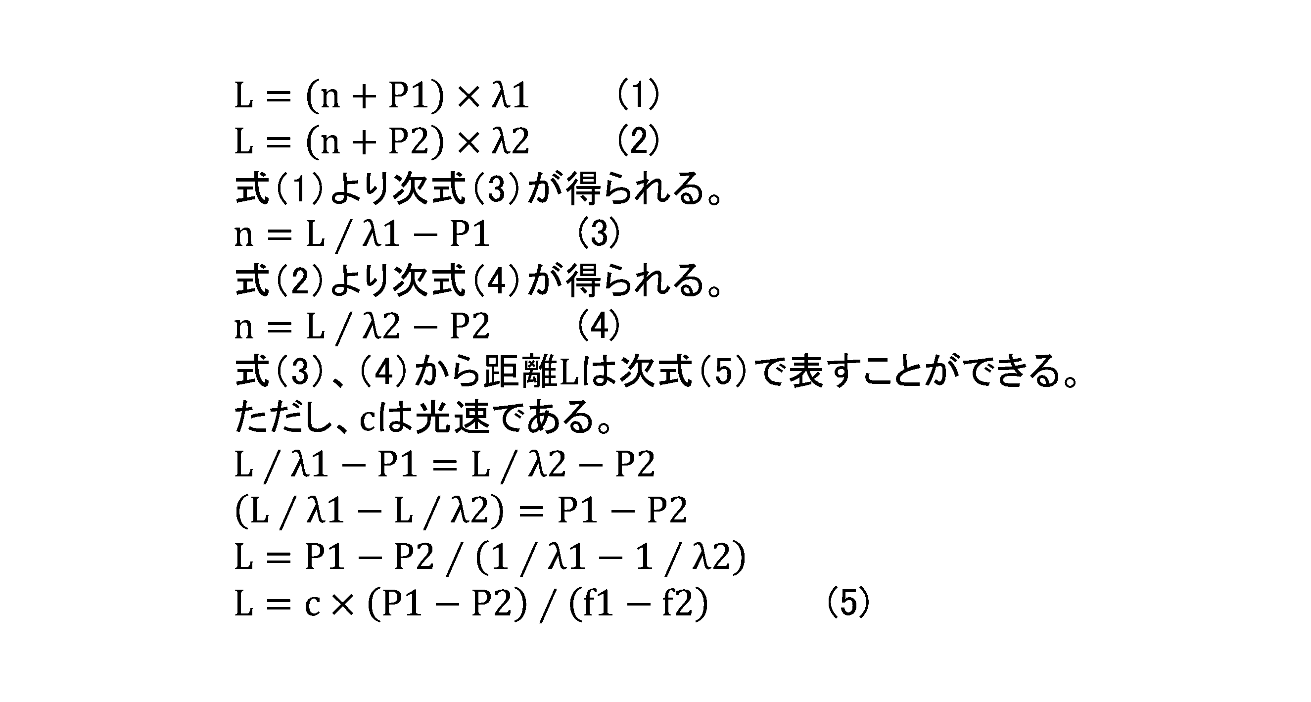
を含む、測位装置。 - 前記第1所定距離をL0、前記第1無線通信部及び前記第2無線通信部の間における前記第1周波数の信号の波数と、前記第1無線通信部及び前記第2無線通信部の間における前記第2周波数の信号の波数とをn、前記第1周波数の信号を前記第2無線通信部が受信したときの位相をP1、前記第2周波数の信号を前記第2無線通信部が受信したときの位相をP2とすると、
前記距離算出部は、次式に従って前記第1無線通信部及び前記第2無線通信部の間の距離Lを求める、請求項1に記載の測位装置。
- 前記同期制御部による前記クロックの補正が行われた状態において、前記移動通信部から送信される前記第1周波数の第1信号を前記第1無線通信部が受信するときの第1位相と、前記移動通信部から送信される前記第2周波数の第2信号を前記第1無線通信部が受信するときの第2位相と、前記移動通信部から送信される前記第1周波数の前記第1信号を前記第2無線通信部が受信するときの第3位相と、前記移動通信部から送信される前記第2周波数の前記第2信号を前記第2無線通信部が受信するときの第4位相とに基づいて、前記移動通信部と前記第1無線通信部との距離と、前記移動通信部と前記第2無線通信部との距離との距離差を算出する距離差算出部と、
前記距離差算出部によって求められる前記距離差に基づいて、前記第1無線通信部及び前記第2無線通信部に対する前記移動通信部の位置を求める測位部と
をさらに含む、請求項1又は2に記載の測位装置。 - 前記第1無線通信部及び前記第2無線通信部は、複数のアンテナを有し、
前記第1無線通信部の前記複数のアンテナで信号が受信される際の位相差に基づいて前記移動通信部から前記第1無線通信部に前記信号が到来する第1到来方向を求める、又は、前記第2無線通信部の前記複数のアンテナで信号が受信される際の位相差に基づいて前記移動通信部から前記第2無線通信部に前記信号が到来する第2到来方向を求める、方向導出部をさらに含み、
前記測位部は、前記距離差算出部によって求められる前記距離差と、前記方向導出部によって求められる前記第1到来方向又は前記第2到来方向とに基づいて、前記第1無線通信部及び前記第2無線通信部に対する前記移動通信部の位置を求める、請求項3に記載の測位装置。 - 前記方向導出部は、前記第1無線通信部の前記複数のアンテナで前記第1信号及び前記第2信号の少なくともいずれか一方が受信される際の位相差から前記第1到来方向を求める、又は、前記第2無線通信部の前記複数のアンテナで前記第1信号及び前記第2信号の少なくともいずれ一方が受信される際の位相差から前記第2到来方向を求める、請求項4に記載の測位装置。
- 前記第1無線通信部から既知の第2所定距離の位置に配置される第3無線通信部をさらに含み、
前記距離算出部は、前記第1無線通信部から送信される前記第1周波数の信号を前記第3無線通信部が受信したときの位相と、前記第1無線通信部から送信される前記第2周波数の信号を前記第3無線通信部が受信したときの位相と、前記第2所定距離とに基づいて前記第1無線通信部及び前記第3無線通信部の間の距離を求め、
前記同期制御部は、前記距離算出部によって算出される前記第1無線通信部及び前記第3無線通信部の間の距離と、前記第2所定距離との差から、前記第1無線通信部及び前記第3無線通信部のクロックが同期するように補正し、
前記距離差算出部は、前記第1無線通信部及び前記第3無線通信部の前記クロックの補正が行われた状態において、前記移動通信部から送信される前記第1周波数の前記第1信号を前記第3無線通信部が受信するときの第5位相と、前記移動通信部から送信される前記第2周波数の前記第2信号を前記第3無線通信部が受信するときの第6位相と、前記第1位相及び前記第2位相とに基づいて、前記移動通信部と前記第1無線通信部との距離と、前記移動通信部と前記第3無線通信部との距離との距離差を算出し、
前記測位部は、前記距離差算出部によって求められる、前記移動通信部と前記第1無線通信部との距離と、前記移動通信部と前記第2無線通信部との距離との距離差と、前記移動通信部と前記第1無線通信部との距離と、前記移動通信部と前記第3無線通信部との距離との距離差とに基づいて、前記第1無線通信部、前記第2無線通信部、及び前記第3無線通信部に対する前記移動通信部の位置を求める、請求項3に記載の測位装置。 - 前記第2無線通信部から既知の第2所定距離の位置に配置される第3無線通信部をさらに含み、
前記距離算出部は、前記第2無線通信部から送信される前記第1周波数の信号を前記第3無線通信部が受信したときの位相と、前記第2無線通信部から送信される前記第2周波数の信号を前記第3無線通信部が受信したときの位相と、前記第2所定距離とに基づいて前記第2無線通信部及び前記第3無線通信部の間の距離を求め、
前記同期制御部は、前記距離算出部によって算出される前記第2無線通信部及び前記第3無線通信部の間の距離と、前記第2所定距離との差から、前記第2無線通信部及び前記第3無線通信部のクロックが同期するように補正し、
前記距離差算出部は、前記移動通信部から送信される前記第1周波数の前記第1信号を前記第3無線通信部が受信するときの第5位相と、前記移動通信部から送信される前記第2周波数の前記第2信号を前記第3無線通信部が受信するときの第6位相と、前記第3位相及び前記第4位相とに基づいて、前記移動通信部と前記第2無線通信部との距離と、前記移動通信部と前記第3無線通信部との距離との距離差を算出し、
前記測位部は、前記距離差算出部によって求められる、前記移動通信部と前記第1無線通信部との距離と、前記移動通信部と前記第2無線通信部との距離との距離差と、前記移動通信部と前記第2無線通信部との距離と、前記移動通信部と前記第3無線通信部との距離との距離差とに基づいて、前記第1無線通信部、前記第2無線通信部、及び前記第3無線通信部に対する前記移動通信部の位置を求める、請求項3に記載の測位装置。 - 前記同期制御部によって前記第1無線通信部及び前記第2無線通信部のクロックが同期するように補正された状態で前記移動通信部から送信される信号を前記第1無線通信部及び前記第2無線通信部がそれぞれ受信した第1時刻及び第2時刻の差と、前記距離差算出部によって算出される前記距離差とに基づいて、前記距離差の品質を評価する、請求項3乃至7のいずれか1項に記載の測位装置。
- 移動通信部の位置を測位する測位装置のクロックを補正するクロック補正方法であって、
前記測位装置は、
第1無線通信部と、
前記第1無線通信部から既知の第1所定距離の位置に配置される第2無線通信部と、
前記第1無線通信部から送信される第1周波数の信号を前記第2無線通信部が受信したときの位相と、前記第1無線通信部から送信される第2周波数の信号を前記第2無線通信部が受信したときの位相と、前記第1所定距離とに基づいて前記第1無線通信部及び前記第2無線通信部の間の距離を求める距離算出部と
を含み、
前記距離算出部によって算出される距離と、前記第1所定距離との差に基づいて、前記第1無線通信部及び前記第2無線通信部のクロックが同期するように補正する、クロック補正方法。
Priority Applications (2)
| Application Number | Priority Date | Filing Date | Title |
|---|---|---|---|
| JP2023564776A JP7615452B2 (ja) | 2021-12-03 | 2022-10-13 | 測位装置、及び、クロック補正方法 |
| US18/677,001 US20240314714A1 (en) | 2021-12-03 | 2024-05-29 | Positioning device and method for correcting clock |
Applications Claiming Priority (2)
| Application Number | Priority Date | Filing Date | Title |
|---|---|---|---|
| JP2021-196786 | 2021-12-03 | ||
| JP2021196786 | 2021-12-03 |
Related Child Applications (1)
| Application Number | Title | Priority Date | Filing Date |
|---|---|---|---|
| US18/677,001 Continuation US20240314714A1 (en) | 2021-12-03 | 2024-05-29 | Positioning device and method for correcting clock |
Publications (1)
| Publication Number | Publication Date |
|---|---|
| WO2023100489A1 true WO2023100489A1 (ja) | 2023-06-08 |
Family
ID=86611913
Family Applications (1)
| Application Number | Title | Priority Date | Filing Date |
|---|---|---|---|
| PCT/JP2022/038185 Ceased WO2023100489A1 (ja) | 2021-12-03 | 2022-10-13 | 測位装置、及び、クロック補正方法 |
Country Status (3)
| Country | Link |
|---|---|
| US (1) | US20240314714A1 (ja) |
| JP (1) | JP7615452B2 (ja) |
| WO (1) | WO2023100489A1 (ja) |
Cited By (1)
| Publication number | Priority date | Publication date | Assignee | Title |
|---|---|---|---|---|
| WO2025240055A1 (en) * | 2024-05-17 | 2025-11-20 | Qorvo Us, Inc. | System and methods for untracked navigation using optimized localization algorithm |
Citations (4)
| Publication number | Priority date | Publication date | Assignee | Title |
|---|---|---|---|---|
| WO2011013220A1 (ja) * | 2009-07-29 | 2011-02-03 | 株式会社日立製作所 | 測位システム及び測位方法 |
| JP2012195840A (ja) * | 2011-03-17 | 2012-10-11 | Renesas Electronics Corp | 通信装置、通信制御方法 |
| JP2016053551A (ja) * | 2014-09-04 | 2016-04-14 | 住友電気工業株式会社 | 距離測定システム、距離測定装置、被測定装置、及び、位置検出システム |
| US20210243716A1 (en) * | 2020-02-04 | 2021-08-05 | Alibaba Group Holding Limited | Distance estimation using signals of different frequencies |
Family Cites Families (4)
| Publication number | Priority date | Publication date | Assignee | Title |
|---|---|---|---|---|
| US10241194B2 (en) * | 2016-03-31 | 2019-03-26 | Voll, Inc. | Mobile device utilizing time of flight for personal security and localization |
| CN114889553B (zh) * | 2017-02-10 | 2024-04-05 | 苹果公司 | 增强型汽车无源进入 |
| US10082556B1 (en) * | 2017-07-12 | 2018-09-25 | Netscout Systems, Inc | Network table error detection and correction using analytics data |
| FR3120130B1 (fr) * | 2021-02-22 | 2023-03-24 | Marbeuf Conseil Et Rech | Procédé de certification de la géolocalisation d’un récepteur |
-
2022
- 2022-10-13 JP JP2023564776A patent/JP7615452B2/ja active Active
- 2022-10-13 WO PCT/JP2022/038185 patent/WO2023100489A1/ja not_active Ceased
-
2024
- 2024-05-29 US US18/677,001 patent/US20240314714A1/en active Pending
Patent Citations (4)
| Publication number | Priority date | Publication date | Assignee | Title |
|---|---|---|---|---|
| WO2011013220A1 (ja) * | 2009-07-29 | 2011-02-03 | 株式会社日立製作所 | 測位システム及び測位方法 |
| JP2012195840A (ja) * | 2011-03-17 | 2012-10-11 | Renesas Electronics Corp | 通信装置、通信制御方法 |
| JP2016053551A (ja) * | 2014-09-04 | 2016-04-14 | 住友電気工業株式会社 | 距離測定システム、距離測定装置、被測定装置、及び、位置検出システム |
| US20210243716A1 (en) * | 2020-02-04 | 2021-08-05 | Alibaba Group Holding Limited | Distance estimation using signals of different frequencies |
Cited By (1)
| Publication number | Priority date | Publication date | Assignee | Title |
|---|---|---|---|---|
| WO2025240055A1 (en) * | 2024-05-17 | 2025-11-20 | Qorvo Us, Inc. | System and methods for untracked navigation using optimized localization algorithm |
Also Published As
| Publication number | Publication date |
|---|---|
| US20240314714A1 (en) | 2024-09-19 |
| JPWO2023100489A1 (ja) | 2023-06-08 |
| JP7615452B2 (ja) | 2025-01-17 |
Similar Documents
| Publication | Publication Date | Title |
|---|---|---|
| EP2653886B1 (en) | Reference signal sending method and system for measuring location, location measuring method, device, and system using same, and time synchronization method and device using same | |
| US20070053340A1 (en) | Time synchronization system and method for synchronizing locating units within a communication system using a known external signal | |
| US8335173B2 (en) | Inserting time of departure information in frames to support multi-channel location techniques | |
| WO2020165227A1 (en) | Apparatus, method and computer program for localizing a tag | |
| US9465099B2 (en) | Method for measuring position of vehicle using cloud computing | |
| WO2020072041A1 (en) | Systems and methods for stereo radar tracking | |
| US10241188B2 (en) | Method and apparatus for obtaining time of arrival TOA when mobile terminal is located | |
| US20090179799A1 (en) | Direction finding system and direction finding apparatus | |
| US10623292B2 (en) | Receiver and event-detection-time-point estimation method | |
| JP7615452B2 (ja) | 測位装置、及び、クロック補正方法 | |
| US20200086901A1 (en) | First train-installed device, method, and recording medium | |
| JP2021099289A (ja) | 車両用通信装置 | |
| CN112204414A (zh) | 蜂窝网络中的载波相位定位 | |
| WO2017145215A1 (ja) | 受信装置 | |
| Herschfelt et al. | Joint positioning-communications system design: Leveraging phase-accurate time-of-flight estimation and distributed coherence | |
| KR101162727B1 (ko) | 위치 측정을 위한 기준신호 송출 방법 및 시스템, 이를 이용한 위치 측정 방법, 장치 및 시스템, 이를 이용한 시각 동기 방법 및 장치 | |
| CN110582707A (zh) | 用于定位系统的无线电接收器 | |
| US12273852B2 (en) | Super resolution radio frequency location determination | |
| US12055645B2 (en) | System and method for positioning and navigation of an object | |
| JP2021060195A (ja) | 物標検出装置の製造方法、車両の製造方法及びプログラム | |
| CN116017685B (zh) | 一种时钟与触发信号精确同步的tdoa短基线定位方法及系统 | |
| KR20170073164A (ko) | 광 전송 지연 보상 방법 및 장치 | |
| KR102041470B1 (ko) | eLoran 기반의 시각동기 장치 및 방법 | |
| JPH11281728A (ja) | キネマテック法gpsと慣性航法装置併用測位方法 | |
| CN115499907B (zh) | 一种基于5g空口的双向高精度时间同步控制方法 |
Legal Events
| Date | Code | Title | Description |
|---|---|---|---|
| 121 | Ep: the epo has been informed by wipo that ep was designated in this application |
Ref document number: 22900923 Country of ref document: EP Kind code of ref document: A1 |
|
| WWE | Wipo information: entry into national phase |
Ref document number: 2023564776 Country of ref document: JP |
|
| NENP | Non-entry into the national phase |
Ref country code: DE |
|
| 122 | Ep: pct application non-entry in european phase |
Ref document number: 22900923 Country of ref document: EP Kind code of ref document: A1 |