WO2023100240A1 - 無線通信システム、無線端末制御方法、制御装置、及び制御プログラム - Google Patents
無線通信システム、無線端末制御方法、制御装置、及び制御プログラム Download PDFInfo
- Publication number
- WO2023100240A1 WO2023100240A1 PCT/JP2021/043842 JP2021043842W WO2023100240A1 WO 2023100240 A1 WO2023100240 A1 WO 2023100240A1 JP 2021043842 W JP2021043842 W JP 2021043842W WO 2023100240 A1 WO2023100240 A1 WO 2023100240A1
- Authority
- WO
- WIPO (PCT)
- Prior art keywords
- wireless
- module
- control unit
- modules
- wireless terminal
- Prior art date
- Legal status (The legal status is an assumption and is not a legal conclusion. Google has not performed a legal analysis and makes no representation as to the accuracy of the status listed.)
- Ceased
Links
Images







Classifications
-
- H—ELECTRICITY
- H04—ELECTRIC COMMUNICATION TECHNIQUE
- H04W—WIRELESS COMMUNICATION NETWORKS
- H04W74/00—Wireless channel access
- H04W74/04—Scheduled access
-
- H—ELECTRICITY
- H04—ELECTRIC COMMUNICATION TECHNIQUE
- H04W—WIRELESS COMMUNICATION NETWORKS
- H04W36/00—Hand-off or reselection arrangements
- H04W36/08—Reselecting an access point
-
- H—ELECTRICITY
- H04—ELECTRIC COMMUNICATION TECHNIQUE
- H04W—WIRELESS COMMUNICATION NETWORKS
- H04W72/00—Local resource management
- H04W72/02—Selection of wireless resources by user or terminal
-
- H—ELECTRICITY
- H04—ELECTRIC COMMUNICATION TECHNIQUE
- H04W—WIRELESS COMMUNICATION NETWORKS
- H04W88/00—Devices specially adapted for wireless communication networks, e.g. terminals, base stations or access point devices
- H04W88/02—Terminal devices
- H04W88/06—Terminal devices adapted for operation in multiple networks or having at least two operational modes, e.g. multi-mode terminals
-
- Y—GENERAL TAGGING OF NEW TECHNOLOGICAL DEVELOPMENTS; GENERAL TAGGING OF CROSS-SECTIONAL TECHNOLOGIES SPANNING OVER SEVERAL SECTIONS OF THE IPC; TECHNICAL SUBJECTS COVERED BY FORMER USPC CROSS-REFERENCE ART COLLECTIONS [XRACs] AND DIGESTS
- Y02—TECHNOLOGIES OR APPLICATIONS FOR MITIGATION OR ADAPTATION AGAINST CLIMATE CHANGE
- Y02D—CLIMATE CHANGE MITIGATION TECHNOLOGIES IN INFORMATION AND COMMUNICATION TECHNOLOGIES [ICT], I.E. INFORMATION AND COMMUNICATION TECHNOLOGIES AIMING AT THE REDUCTION OF THEIR OWN ENERGY USE
- Y02D30/00—Reducing energy consumption in communication networks
- Y02D30/70—Reducing energy consumption in communication networks in wireless communication networks
Definitions
- the present invention relates to technology for controlling a wireless terminal that performs wireless communication by switching between multiple channels.
- a wireless communication system composed of base stations and wireless terminals is known.
- a typical example of a wireless communication system is a wireless LAN (Local Area Network) for public use.
- a wireless LAN for public use for example, a use case is assumed in which data is transmitted from a base station to a wireless terminal such as a computer terminal or a smartphone terminal.
- IoT Internet of Things
- the use of the unlicensed Sub-1 GHz band has been institutionalized in countries around the world (see Non-Patent Document 1 and Non-Patent Document 2).
- the 920 MHz band is allocated as the frequency band for electronic tag systems.
- LPWA (Low Power Wide Area) wireless communication systems such as LoRa (registered trademark) and WiSUN (registered trademark) are known as active electronic tag systems.
- IEEE 802.11ah which is one of the wireless LAN standards, is being considered.
- One object of the present invention is to provide a technology that can simplify processing for switching channels used by wireless terminals.
- a radio communication system includes a radio terminal and a control unit.
- a wireless terminal includes a plurality of wireless modules that perform wireless communication with each of a plurality of base stations using different channels.
- a wireless terminal uses one of a plurality of wireless modules as a module to be used, and stops data transmission from wireless modules other than the module to be used.
- the control unit switches modules to be used in the wireless terminal such that the transmission time rate of each of the plurality of wireless modules does not exceed a predetermined upper limit.
- a second aspect relates to a radio terminal control method for controlling a radio terminal.
- a wireless terminal includes a plurality of wireless modules that perform wireless communication with each of a plurality of base stations using different channels.
- the wireless terminal control method is a process of selecting one of a plurality of wireless modules as a module to be used; a process of stopping data transmission from wireless modules other than the used module; and a process of switching the module used in the wireless terminal so that the transmission time rate of each of the plurality of wireless modules does not exceed a predetermined upper limit.
- a third aspect relates to a control device that controls a wireless terminal.
- a wireless terminal includes a plurality of wireless modules that perform wireless communication with each of a plurality of base stations using different channels.
- the controller comprises one or more processors.
- the one or more processors are a process of selecting one of a plurality of wireless modules as a module to be used; a process of stopping data transmission from wireless modules other than the used module; and a process of switching modules to be used in the wireless terminal so that the transmission time rate of each of the plurality of wireless modules does not exceed a predetermined upper limit.
- a fourth aspect relates to a control program executed by a computer.
- the control program causes the computer to execute the wireless terminal control method according to the second aspect.
- the control program causes a computer to implement the control device according to the third aspect.
- a wireless terminal includes a plurality of wireless modules that perform wireless communication with each of a plurality of base stations using different channels.
- the control unit switches a module to be used by the wireless terminal among the plurality of wireless modules.
- the channel used for wireless communication can be easily switched. Since there is no need to switch channels within a single wireless module, it is possible to simplify processing required for channel switching.
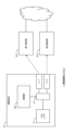
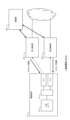
- FIG. 1 is a block diagram showing a configuration example of a radio communication system according to an embodiment
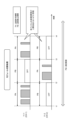
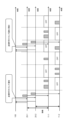
- FIG. 4 is a timing chart for explaining an overview of module switching processing according to the embodiment
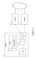
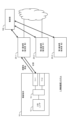
- 1 is a block diagram showing a configuration example of a radio communication system according to a first embodiment
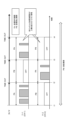
- FIG. 4 is a timing chart for explaining an example of module switching processing according to the first embodiment
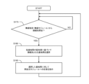
- 4 is a flowchart briefly showing processing related to module switching processing according to the first embodiment
- FIG. 11 is a block diagram showing a configuration example of a radio communication system according to a second embodiment
- FIG. FIG. 11 is a timing chart for explaining an example of module switching processing according to the second embodiment
- FIG. FIG. 12 is a block diagram showing a configuration example of a radio communication system according to a third embodiment
- FIG. 14 is a timing chart for explaining an example of module switching processing according to the third embodiment
- FIG. FIG. 12 is a block diagram showing a configuration example of a radio communication system according to a fourth embodiment
- FIG. FIG. 12 is a block diagram showing another configuration example of the radio communication system according to the fourth embodiment
- FIG. FIG. 14 is a timing chart for explaining an example of module switching processing according to the fourth embodiment
- FIG. FIG. 12 is a block diagram showing a configuration example of a radio communication system according to a fifth embodiment
- FIG. FIG. 14 is a timing chart for explaining an example of timing setting processing according to the fifth embodiment
- FIG. FIG. 14 is a flow chart showing processing by a control unit according to a fifth embodiment
- FIG. 12 is a block diagram showing a configuration example of a radio communication system according to a sixth embodiment
- FIG. 14 is a timing chart for explaining an example of connection processing according to the sixth embodiment
- FIG. 16 is a flow chart showing processing by a control unit according to a sixth embodiment
- FIG. 1 is a block diagram showing a configuration example of a radio communication system 1 according to this embodiment.
- a radio communication system 1 includes a radio terminal 10 and a plurality of base stations 20 .
- the wireless terminal 10 and each base station 20 constitute a wireless communication network and perform wireless communication with each other.
- the wireless communication system 1 is a wireless LAN system
- the base station 20 is a wireless LAN access point.
- the radio communication system 1 performs radio communication using, for example, the unlicensed Sub-1 GHz band.
- the radio communication system 1 performs radio communication using the 920 MHz band.
- the wireless terminal 10 can perform wireless communication by switching between a plurality of channels (frequency channels). More specifically, the wireless terminal 10 includes a plurality of wireless modules 11 that perform wireless communication on different channels that do not overlap each other. Each wireless module 11 includes, for example, a network interface controller (network interface card). The plurality of wireless modules 11 are respectively connected to the plurality of base stations 20 and perform wireless communication with the plurality of base stations 20 .
- a network interface controller network interface card
- the wireless terminal 10 includes a first wireless module 11-1 and a second wireless module 11-2.
- the first wireless module 11-1 is set to perform wireless communication on the first channel CH-1.
- the first radio module 11-1 is connected to the first base station 20-1 and performs radio communication with the first base station 20-1 on the first channel CH-1.
- the second radio module 11-2 is set to perform radio communication on a second channel CH-2 that does not overlap with the first channel CH-1.
- the second radio module 11-2 is connected to the second base station 20-2 and performs radio communication with the second base station 20-2 on the second channel CH-2.
- the channel used for wireless communication can be easily switched.
- One of the plurality of wireless modules 11 that is selectively used is hereinafter referred to as a "use module 11S”.
- the used module 11S can also be called a "selected module”.
- module switching process the process of switching the used module 11S in the wireless terminal 10 is hereinafter referred to as "module switching process”.
- the wireless communication system 1 further includes a "control section 100" that manages and controls the module switching process.
- the control unit 100 selects one of the plurality of wireless modules 11 included in the wireless terminal 10 as the module to be used 11S. Also, the control unit 100 monitors and manages the transmission time and transmission time rate of each channel of the plurality of wireless modules 11 . Then, the control unit 100 performs module switching processing for switching the module 11S to be used so that the transmission time rate of each channel of the plurality of wireless modules 11 does not exceed a predetermined upper limit.
- control unit 100 is included in the wireless terminal 10.
- control unit 100 may be connected to the wireless terminal 10 and control the wireless terminal 10 from the outside.
- control unit 100 may be included in the base station 20 and control the wireless terminal 10 through communication.
- control unit 100 may be connected to the base station 20 and control the wireless terminal 10 via the base station 20 .
- the control unit 100 can also be called a "control device".
- the control unit 100 may be a computer including one or more processors 110 (hereinafter simply referred to as “processors 110") and one or more storage devices 120 (hereinafter simply referred to as “storage devices 120").
- processors 110 includes a CPU (Central Processing Unit).
- the storage device 120 stores various information necessary for processing by the processor 110 . Examples of the storage device 120 include volatile memory, nonvolatile memory, HDD (Hard Disk Drive), SSD (Solid State Drive), and the like.
- the control program 130 is a computer program executed by the processor 110 .
- the functions of the control unit 100 are implemented by the processor 110 executing the control program 130 .
- the control program 130 is stored in the storage device 120 .
- the control program 130 may be recorded on a computer-readable recording medium.
- the control program 130 may be provided to the control device 30 via a network.
- FIG. 2 is a timing chart for explaining an overview of module switching processing according to the present embodiment.
- switching between the first wireless module 11-1 (first channel CH-1) and the second wireless module 11-2 (second channel CH-2) is considered.
- the control unit 100 selects the first wireless module 11-1 as the module to be used 11S.
- the control unit 100 permits data transmission from the first wireless module 11-1, but prohibits data transmission from the second wireless module 11-2.
- the period from time t1 to t2 is the transmission permitted period PA for the first wireless module 11-1 and the transmission prohibited period PB for the second wireless module 11-2.
- the radio terminal 10 uses the first radio module 11-1 as the module 11S to be used, and performs radio communication with the first base station 20-1 on the first channel CH-1. Meanwhile, the wireless terminal 10 stops data transmission from the second wireless module 11-2.
- the control unit 100 constantly monitors the transmission time and transmission time rate of the first wireless module 11-1.
- control unit 100 performs module switching processing to switch the module 11S used from the first wireless module 11-1 to the second wireless module 11-2.
- the control unit 100 selects the second wireless module 11-2 as the module to be used 11S.
- the control unit 100 permits data transmission from the second wireless module 11-2, but prohibits data transmission from the first wireless module 11-1.
- the period from time t2 to t3 is the transmission prohibited period PB for the first wireless module 11-1 and the transmission permitted period PA for the second wireless module 11-2.
- the radio terminal 10 uses the second radio module 11-2 as the module 11S to be used, and performs radio communication with the second base station 20-2 on the second channel CH-2. Meanwhile, the wireless terminal 10 stops data transmission from the first wireless module 11-1.
- the control unit 100 constantly monitors the transmission time and transmission time rate of the second wireless module 11-2.
- the control unit 100 performs module switching processing to switch the module 11S used from the second wireless module 11-2 to the first wireless module 11-1.
- the period from time t3 to t4 is the same as the period from time t1 to t2.
- control unit 100 may perform module switching processing at regular time intervals.
- control unit 100 may perform module switching processing when the communication quality of the used module 11S has deteriorated.
- control section 100 according to the present embodiment performs module switching processing so that the transmission time rate of each wireless module 11 (each channel) does not exceed a predetermined upper limit. Therefore, the control section 100 monitors and manages the transmission time of each of the plurality of wireless modules 11 in the measurement period PM. Then, the control unit 100 performs module switching processing so that the transmission time of each wireless module 11 in the measurement period PM is equal to or less than a certain value.
- the control unit 100 stops using that wireless module 11 .
- the control unit 100 stops data transmission from the wireless terminal 10 .
- the wireless terminal 10 includes a plurality of wireless modules 11 that perform wireless communication with each of the plurality of base stations 20 on different channels.
- the control unit 100 performs module switching processing for switching the module 11S used by the wireless terminal 10 among the plurality of wireless modules 11 .
- the control unit 100 performs module switching processing so that the transmission time rate of each of the plurality of wireless modules 11 does not exceed a predetermined upper limit.
- the channel used for wireless communication can be easily switched. Since there is no need to switch channels within a single wireless module 11, it is possible to simplify processing required for channel switching. In addition, since the wireless terminal 10 does not need to be restarted for channel switching, the communication interruption time is reduced and service quality deterioration is prevented.
- each channel can be used up to the upper limit of the transmission time rate. That is, it is possible to increase the transmission time rate of the radio terminal 10 as a whole and effectively improve the throughput.
- the wireless terminal 10 includes a plurality of wireless modules 11, redundancy is ensured and reliability is improved.
- FIG. 3 is a block diagram showing a configuration example of a radio communication system 1 according to a first embodiment.
- the controller 100 is included in the wireless terminal 10 . That is, the radio terminal 10 has the control section 100 .
- the wireless terminal 10 further includes a plurality of wireless modules 11 , higher layers 12 and a selector 13 .
- the control unit 100 selects one of the plurality of wireless modules 11 as the module to be used 11S.
- the control unit 100 notifies the selector 13 of the selected module 11S to be used.
- the selector 13 receives transmission data from the upper layer 12 and outputs the transmission data to the usage module 11S.
- the selector 13 does not pass the transmission data to the wireless modules 11 other than the module 11S in use.
- the usage module 11S transmits transmission data from the upper layer 12, and the wireless modules 11 other than the usage module 11S stop data transmission.
- the control unit 100 monitors and manages the transmission time and transmission time rate of each of the multiple wireless modules 11 . Furthermore, the control unit 100 performs module switching processing for switching the module 11S to be used. Although the module switching process can be triggered arbitrarily, the control unit 100 performs the module switching process so that at least the transmission time rate of each of the plurality of wireless modules 11 does not exceed a predetermined upper limit.
- FIG. 4 is a timing chart for explaining an example of module switching processing according to the first embodiment. The description overlapping with that of FIG. 2 above will be omitted as appropriate.
- the control unit 100 manages (monitors) the transmission time rate of each of the first wireless module 11-1 and the second wireless module 11-2. For example, the control unit 100 manages (monitors) the transmission time of each of the first wireless module 11-1 and the second wireless module 11-2 in the measurement period PM. Then, the control unit 100 performs module switching processing so that the transmission time of each wireless module 11 in the measurement period PM is equal to or less than a certain value. For example, when the transmission time rate of the used module 11S reaches a predetermined upper limit, the control unit 100 performs module switching processing. It is to be.
- FIG. 5 is a flowchart briefly showing processing related to module switching processing.
- control unit 100 selects one of the plurality of wireless modules 11 as the module 11S to be used according to the initial settings.
- the wireless terminal 10 performs wireless communication with the base station 20 using the module 11S used.
- step S110 the control unit 100 determines whether there is a trigger for module switching processing. In other words, the control unit 100 determines whether or not a condition for executing the module switching process (hereinafter referred to as "module switching condition") is satisfied.
- the module switching condition is that the transmission time rate of the used module 11S reaches a predetermined upper limit. Other examples of module switching conditions will be described later. If the module switching condition is not satisfied (step S110; No), the process returns to step S110. On the other hand, if the module switching condition is satisfied (step S110; Yes), the process proceeds to step S120.
- step S120 the control unit 100 performs module switching processing to switch the used module 11S.
- step S130 the wireless terminal 10 performs wireless communication with the base station 20 using the switched module 11S. The process returns to step S110.
- FIG. 6 is a block diagram showing a configuration example of a radio communication system 1 according to a second embodiment. Explanations overlapping with those of the first embodiment will be omitted as appropriate.
- a control unit 100 is included in the wireless terminal 10 .
- the control unit 100 performs module switching processing so that at least the transmission time rate of each of the plurality of wireless modules 11 does not exceed a predetermined upper limit.
- the control unit 100 includes a timer 140 that measures a certain period of time.
- the control unit 100 may refer to the timer 140 and perform the module switching process at regular time intervals. That is, the module switching condition in step S110 may include "that a certain period of time has passed since the use of the module 11S to be used started". Thereby, the transmission time of each wireless module 11 is ensured.
- FIG. 7 is a timing chart for explaining an example of module switching processing according to the second embodiment. The description overlapping with that of FIG. 2 above will be omitted as appropriate.
- the control unit 100 performs module switching processing at regular time intervals, that is, each time a timeout occurs.
- the control unit 100 also manages the transmission time rate of each wireless module 11, and performs module switching processing so that the transmission time rate does not exceed a predetermined upper limit.
- FIG. 8 is a block diagram showing a configuration example of a radio communication system 1 according to a third embodiment. Explanations overlapping with those of the first embodiment will be omitted as appropriate.
- a control unit 100 is included in the wireless terminal 10 .
- the control unit 100 performs module switching processing so that at least the transmission time rate of each of the plurality of wireless modules 11 does not exceed a predetermined upper limit.
- the control unit 100 includes a communication state monitoring unit 150.
- the communication status monitor 150 monitors the communication status of each of the wireless modules 11 .
- the communication state monitoring unit 150 monitors the communication quality of the module 11S used. Communication quality includes throughput, communication delay, received radio wave intensity, waiting time for carrier sense, and the like. Then, when the communication quality of the used module 11S drops below the threshold, the control unit 100 may perform module switching processing. That is, the module switching condition in step S110 may include "that the communication quality of the used module 11S falls below a threshold". This makes it possible to avoid deterioration in communication quality.
- FIG. 9 is a timing chart for explaining an example of module switching processing according to the third embodiment. The description overlapping with that of FIG. 2 above will be omitted as appropriate.
- the control unit 100 monitors the communication state, and performs module switching processing when the communication quality of the used module 11S drops below a threshold value.
- the control unit 100 also manages the transmission time rate of each wireless module 11, and performs module switching processing so that the transmission time rate does not exceed a predetermined upper limit.
- FIGS. 10 and 11 are block diagrams showing configuration examples of a radio communication system 1 according to a fourth embodiment. Explanations overlapping with those of the first embodiment will be omitted as appropriate.
- a control unit 100 is included in the wireless terminal 10 .
- the control unit 100 performs module switching processing so that at least the transmission time rate of each of the plurality of wireless modules 11 does not exceed a predetermined upper limit.
- the fourth embodiment there are multiple upper layers 12 that are data transmission sources.
- a plurality of wireless modules 11 and a plurality of upper layers 12 are associated with each other. That is, the plurality of wireless modules 11 are assigned to each of the plurality of upper layers 12 .
- a plurality of wireless modules 11 are used for data transmission from each of a plurality of upper layers 12 .
- the first radio module 11-1 is used for data transmission from the first upper layer 12-1 (eg IoT).
- the second radio module 11-2 is used for data transmission from a second upper layer 12-2 (eg file transfer).
- a second upper layer 12-2 eg file transfer
- the wireless terminal 10 may include a routing section that distributes transmission data from multiple upper layers 12 to multiple wireless modules 11 .
- Multipath-TCP MPTCP
- MPTCP allows data of multiple TCP connections to be transmitted by separate wireless modules 11 .
- the wireless terminal 10 includes multiple queues 14 for each of multiple wireless modules 11 .
- the first queue 14-1 is provided for the first wireless module 11-1
- the second queue 14-2 is provided for the second wireless module 11-2. Due to suspension of use of the wireless modules 11 other than the module 11S in use, transmission standby may occur in the corresponding queue 14 .
- FIG. 12 is a timing chart for explaining a technique for suppressing delays caused by waiting for transmission in the queue 14.
- FIG. 12 The description overlapping with that of FIG. 2 above will be omitted as appropriate.
- the frequency of channel switching processing is set higher than in other embodiments.
- the cycle of channel switching processing may be set by a timer. By setting the frequency of channel switching processing to be high, waiting for transmission in each queue 14 is suppressed. Also, the timing of data transfer from the queue 14 may be adjusted so that data is not discarded in the wireless module 11 .
- FIG. 13 is a block diagram showing a configuration example of a radio communication system 1 according to a fifth embodiment. Explanations overlapping with those of the first embodiment will be omitted as appropriate.
- the controller 100 is connected to multiple base stations 20 .
- the control unit 100 manages and controls the wireless terminal 10 via the base station 20 .
- the control unit 100 manages and sets (specifies) the transmission permission timing of each wireless module 11 of the wireless terminal 10 .
- the control unit 100 assigns non-overlapping transmission permission timings (transmission permission periods PA) to the plurality of wireless modules 11 of the wireless terminal 10 .
- non-overlapping transmission prohibited timings transmission prohibited periods PB
- the control unit 100 assigns transmission permission timings so that the transmission time rate of each wireless module 11 does not exceed a predetermined upper limit.
- the control unit 100 sets non-overlapping transmission permission timings for the plurality of wireless modules 11 via each of the plurality of base stations 20 .
- Each wireless module 11 of the wireless terminal 10 operates as a use module 11S at the set transmission permission timing, and stops data transmission at times other than the transmission permission timing.
- FIG. 14 is a timing chart for explaining an example of timing setting processing according to the fifth embodiment. Connection processing is performed between the first wireless module 11-1 and the first base station 20-1. Also, connection processing is performed between the second wireless module 11-2 and the second base station 20-2.
- the control unit 100 assigns non-overlapping transmission permission timings (transmission permission periods PA) to the first wireless module 11-1 and the second wireless module 11-2.
- the control unit 100 notifies the first base station 20-1 of the transmission permission timing of the first radio module 11-1.
- the first base station 20-1 sets the transmission permission timing to the first radio module 11-1.
- TWT Target Wake Time
- the control unit 100 notifies the second base station 20-2 of the transmission permission timing of the second wireless module 11-2.
- the second base station 20-2 sets the transmission permission timing to the second wireless module 11-2.
- Each of the first wireless module 11-1 and the second wireless module 11-2 operates as the use module 11S at the set transmission permission timing, and stops data transmission at times other than the transmission permission timing.
- the control unit 100 may update the transmission permission timing of each wireless module 11.
- the control unit 100 grasps the communication quality and traffic conditions of each of the plurality of base stations 20 .
- the traffic situation may include the transmission hour rate of each wireless module 11 and the transmission hour rate of the base station 20 .
- the control unit 100 updates the transmission permission timing of each wireless module 11 based on the communication quality and traffic conditions of each base station 20 .
- the control unit 100 updates the transmission permission timing so that the transmission time rate of each wireless module 11 does not exceed a predetermined upper limit.
- FIG. 15 is a flowchart showing processing by the control unit 100 according to the fifth embodiment.
- step S140 the control unit 100 determines whether or not a connection status update notification has been received from any of the base stations 20.
- the connection state update notification is a notification indicating that the connection state between the base station 20 and the wireless terminal 10 (wireless module 11) has been updated. If the connection status update notification has been received (step S140; Yes), the process proceeds to step S150.
- step S150 the control unit 100 determines the transmission permission timing of each wireless module 11 under the control of the base station 20. At this time, the transmission permission timing of each wireless module 11 is determined so that the transmission permission timings of the plurality of wireless modules 11 do not overlap.
- step S160 the control unit 100 sets the transmission permission timing to each wireless module 11 via the base station 20 concerned.
- FIG. 16 is a block diagram showing a configuration example of a radio communication system 1 according to a sixth embodiment. Explanations overlapping with those of the first embodiment will be omitted as appropriate.
- the controller 100 is connected to multiple base stations 20 .
- the control unit 100 manages and controls the wireless terminal 10 via the base station 20 .
- connection processing between the wireless module 11 and the base station 20 will be considered. Assume that when the wireless module 11 connects to the base station 20, there are a plurality of base stations 20 as connection destination candidates. In this case, the control unit 100 designates the optimum one from among the plurality of base stations 20 (connection destination candidates).
- the control unit 100 constantly monitors the states of the multiple base stations 20 .
- the control unit 100 sets the priority of each base station 20 based on the state of each base station 20 (eg, congestion status, downlink traffic, transmission time rate as a base station, etc.). For example, the control unit 100 grasps the congestion status of the base station 20 based on the available bandwidth, the number of connected terminals, and the like. Then, the control unit 100 lowers the priority of the base station 20 that has little spare radio resource. As another example, if the downlink traffic from the base station 20 to the wireless terminal 10 is also restricted in the transmission time rate, the control unit 100 grasps the current situation of the downlink traffic and the transmission time rate. Then, the control unit 100 lowers the priority of the base station 20 with a small margin of the transmission time rate.
- the control unit 100 selects one base station 20 to which the wireless module 11 is connected according to the priority of each base station 20 .
- the control unit 100 is connected to a first base station 20-1, a second base station 20-2, and a third base station 20-3. If the first base station 20-1 has the highest priority among these, the control unit 100 selects the first base station 20-1 as the connection destination. This makes it possible to appropriately select the connection destination of the wireless module 11 according to the situation on the base station 20 side.
- FIG. 17 is a timing chart for explaining an example of connection processing according to the sixth embodiment.
- the first wireless module 11-1 of the wireless terminal 10 inquires of the surrounding base station 20 about the connection destination.
- Each base station 20 notifies the control unit 100 of reception of the connection destination inquiry.
- the control unit 100 selects the connection destination of the first wireless module 11-1 from among the plurality of base stations 20 according to the priority of the plurality of base stations 20.
- the priority of the first base station 20-1 is the highest, and the first base station 20-1 is selected.
- the control unit 100 instructs the selected first base station 20-1 to respond to the first wireless module 11-1.
- the first base station 20-1 returns a response to the first wireless module 11-1, which is the connection destination inquiry source.
- connection processing is performed between the first wireless module 11-1 and the first base station 20-1.
- the second wireless module 11-2 of the wireless terminal 10 inquires of the surrounding base station 20 about the connection destination.
- Each base station 20 notifies the control unit 100 of reception of the connection destination inquiry.
- the control unit 100 selects the connection destination of the second wireless module 11 - 2 from among the plurality of base stations 20 according to the priority of the plurality of base stations 20 .
- the second base station 20-2 has the highest priority and is selected.
- the control unit 100 instructs the selected second base station 20-2 to respond to the second wireless module 11-2.
- the second base station 20-2 returns a response to the second wireless module 11-2, which is the connection destination inquiry source.
- connection processing is performed between the second wireless module 11-2 and the second base station 20-2.
- FIG. 18 is a flowchart showing processing by the control unit 100 according to the sixth embodiment.
- step S ⁇ b>170 the control unit 100 determines whether or not it has received a connection destination inquiry reception notification from at least one base station 20 .
- the connection destination inquiry reception notification is a notification indicating that the base station 20 has received a connection destination inquiry from the wireless terminal 10 (wireless module 11). If the connection destination inquiry reception notification has been received (step S170; Yes), the process proceeds to step S180.
- step S180 the control unit 100 selects one base station 20 to which the wireless module 11 is connected, based on the priority of each base station 20.
- step S190 the control unit 100 instructs the selected base station 20 to respond to the wireless module 11 that is the connection destination inquiry source.
- the wireless terminal 10 includes a plurality of wireless modules 11 that perform wireless communication with each of the plurality of base stations 20 on different channels.
- the control unit 100 performs module switching processing for switching the module 11S used by the wireless terminal 10 among the plurality of wireless modules 11 .
- the control unit 100 performs module switching processing so that the transmission time rate of each of the plurality of wireless modules 11 does not exceed a predetermined upper limit.
- the channel used for wireless communication can be easily switched. Since there is no need to switch channels within a single wireless module 11, it is possible to simplify processing required for channel switching. In addition, since the wireless terminal 10 does not need to be restarted for channel switching, the communication interruption time is reduced and service quality deterioration is prevented.
- each channel can be used up to the upper limit of the transmission time rate. That is, it is possible to increase the transmission time rate of the radio terminal 10 as a whole and effectively improve the throughput.
- the wireless terminal 10 includes a plurality of wireless modules 11, redundancy is ensured and reliability is improved.
- 1... wireless communication system 10... wireless terminal, 11... wireless module 11, 11-1... first wireless module, 11-2... second wireless module, 11S... used module, 12... upper layer, 13... selector, 20 ... base station, 20-1 ... first base station, 20-2 ... second base station, 100 ... control unit, 110 ... processor, 120 ... storage device, 130 ... control program, 140 ... timer, 150 ... communication status monitoring part, PA... transmission permitted period, PB... transmission prohibited period
Landscapes
- Engineering & Computer Science (AREA)
- Computer Networks & Wireless Communication (AREA)
- Signal Processing (AREA)
- Mobile Radio Communication Systems (AREA)
Abstract
Description
無線通信システムは、無線端末と制御部とを備える。
無線端末は、複数の基地局のそれぞれと互いに異なるチャネルで無線通信を行う複数の無線モジュールを備える。
無線端末は、複数の無線モジュールのうち1つを使用モジュールとして使用し、使用モジュール以外の無線モジュールからのデータ送信を停止する。
制御部は、複数の無線モジュールの各々の送信時間率が所定の上限を超えないように、無線端末における使用モジュールを切り替える。
無線端末は、複数の基地局のそれぞれと互いに異なるチャネルで無線通信を行う複数の無線モジュールを備える。
無線端末制御方法は、
複数の無線モジュールのうち1つを使用モジュールとして選択する処理と、
使用モジュール以外の無線モジュールからのデータ送信を停止させる処理と、
複数の無線モジュールの各々の送信時間率が所定の上限を超えないように、無線端末における使用モジュールを切り替える処理と
を含む。
無線端末は、複数の基地局のそれぞれと互いに異なるチャネルで無線通信を行う複数の無線モジュールを備える。
制御装置は、1又は複数のプロセッサを備える。
1又は複数のプロセッサは、
複数の無線モジュールのうち1つを使用モジュールとして選択する処理と、
使用モジュール以外の無線モジュールからのデータ送信を停止させる処理と、
複数の無線モジュールの各々の送信時間率が所定の上限を超えないように、無線端末における使用モジュールを切り替える処理と
を実行するように構成される。
図1は、本実施の形態に係る無線通信システム1の構成例を示すブロック図である。無線通信システム1は、無線端末10と複数の基地局20を含んでいる。無線端末10と各基地局20は、無線通信ネットワークを構成し、互いに無線通信を行う。例えば、無線通信システム1は無線LANシステムであり、基地局20は無線LANのアクセスポイントである。無線通信システム1は、例えば、アンライセンスのSub-1GHz帯を利用して無線通信を行う。例えば、無線通信システム1は、920MHz帯を利用して無線通信を行う。
以上に説明されたように、本実施の形態によれば、無線端末10は、複数の基地局20のそれぞれと互いに異なるチャネルで無線通信を行う複数の無線モジュール11を備えている。制御部100は、複数の無線モジュール11のうち無線端末10が使用する使用モジュール11Sを切り替えるモジュール切替処理を行う。特に、制御部100は、複数の無線モジュール11の各々の送信時間率が所定の上限を超えないようにモジュール切替処理を行う。
2-1.第1の実施の形態
図3は、第1の実施の形態に係る無線通信システム1の構成例を示すブロック図である。第1の例では、制御部100は無線端末10に含まれている。つまり、無線端末10が制御部100を備えている。無線端末10は、更に、複数の無線モジュール11、上位レイヤ12、及びセレクタ13を含んでいる。
することである。
図6は、第2の実施の形態に係る無線通信システム1の構成例を示すブロック図である。第1の実施の形態と重複する説明は適宜省略する。制御部100は、無線端末10に含まれている。制御部100は、少なくとも、複数の無線モジュール11の各々の送信時間率が所定の上限を超えないようにモジュール切替処理を行う。
図8は、第3の実施の形態に係る無線通信システム1の構成例を示すブロック図である。第1の実施の形態と重複する説明は適宜省略する。制御部100は、無線端末10に含まれている。制御部100は、少なくとも、複数の無線モジュール11の各々の送信時間率が所定の上限を超えないようにモジュール切替処理を行う。
図10及び図11は、第4の実施の形態に係る無線通信システム1の構成例を示すブロック図である。第1の実施の形態と重複する説明は適宜省略する。制御部100は、無線端末10に含まれている。制御部100は、少なくとも、複数の無線モジュール11の各々の送信時間率が所定の上限を超えないようにモジュール切替処理を行う。
図13は、第5の実施の形態に係る無線通信システム1の構成例を示すブロック図である。第1の実施の形態と重複する説明は適宜省略する。第5の実施の形態では、制御部100は、複数の基地局20に接続されている。制御部100は、基地局20を介して無線端末10の管理及び制御を行う。特に、制御部100は、無線端末10の各無線モジュール11の送信許可タイミングの管理及び設定(指定)を行う。
図16は、第6の実施の形態に係る無線通信システム1の構成例を示すブロック図である。第1の実施の形態と重複する説明は適宜省略する。第6の実施の形態では、制御部100は、複数の基地局20に接続されている。制御部100は、基地局20を介して無線端末10の管理及び制御を行う。
以上に説明されたように、本実施の形態によれば、無線端末10は、複数の基地局20のそれぞれと互いに異なるチャネルで無線通信を行う複数の無線モジュール11を備えている。制御部100は、複数の無線モジュール11のうち無線端末10が使用する使用モジュール11Sを切り替えるモジュール切替処理を行う。特に、制御部100は、複数の無線モジュール11の各々の送信時間率が所定の上限を超えないようにモジュール切替処理を行う。
Claims (8)
- 複数の基地局のそれぞれと互いに異なるチャネルで無線通信を行う複数の無線モジュールを備える無線端末と、
制御部と
を備え、
前記無線端末は、前記複数の無線モジュールのうち1つを使用モジュールとして使用し、前記使用モジュール以外の無線モジュールからのデータ送信を停止し、
前記制御部は、前記複数の無線モジュールの各々の送信時間率が所定の上限を超えないように、前記無線端末における前記使用モジュールを切り替える
無線通信システム。 - 請求項1に記載の無線通信システムであって、
前記制御部は、測定周期における前記複数の無線モジュールの各々の送信時間を監視し、前記測定周期における前記複数の無線モジュールの各々の前記送信時間が一定値以下となるように、前記無線端末における前記使用モジュールを切り替える
無線通信システム。 - 請求項1又は2に記載の無線通信システムであって、
前記制御部は、モジュール切替条件が成立するか否か判定し、前記モジュール切替条件が成立した場合に前記使用モジュールを切り替え、
前記モジュール切替条件は、前記使用モジュールの使用開始から一定時間が経過すること、あるいは、前記使用モジュールの通信品質が閾値以下に低下することを含む
無線通信システム。 - 請求項1又は2に記載の無線通信システムであって、
前記複数の無線モジュールは、データ送信元の複数の上位レイヤのそれぞれに割り当てられ、前記複数の上位レイヤのそれぞれからのデータ送信に使用される
無線通信システム。 - 請求項1又は2に記載の無線通信システムであって、
前記制御部は、前記複数の基地局に接続されており、
前記制御部は、前記複数の基地局のそれぞれを介して、前記無線端末の前記複数の無線モジュールに互いに重複しない送信許可タイミングを設定し、
前記複数の無線モジュールの各々は、前記送信許可タイミングにおいて前記使用モジュールとして作動し、前記送信許可タイミング以外ではデータ送信を停止する
無線通信システム。 - 複数の基地局のそれぞれと互いに異なるチャネルで無線通信を行う複数の無線モジュールを備える無線端末を制御する無線端末制御方法であって、
前記複数の無線モジュールのうち1つを使用モジュールとして選択する処理と、
前記使用モジュール以外の無線モジュールからのデータ送信を停止させる処理と、
前記複数の無線モジュールの各々の送信時間率が所定の上限を超えないように、前記無線端末における前記使用モジュールを切り替える処理と
を含む
無線端末制御方法。 - 複数の基地局のそれぞれと互いに異なるチャネルで無線通信を行う複数の無線モジュールを備える無線端末を制御する制御装置であって、
1又は複数のプロセッサを備え、
前記1又は複数のプロセッサは、
前記複数の無線モジュールのうち1つを使用モジュールとして選択する処理と、
前記使用モジュール以外の無線モジュールからのデータ送信を停止させる処理と、
前記複数の無線モジュールの各々の送信時間率が所定の上限を超えないように、前記無線端末における前記使用モジュールを切り替える処理と
を実行するように構成された
制御装置。 - コンピュータによって実行され、請求項7に記載の制御装置を前記コンピュータに実現させる制御プログラム。
Priority Applications (3)
| Application Number | Priority Date | Filing Date | Title |
|---|---|---|---|
| JP2023564298A JP7687436B2 (ja) | 2021-11-30 | 2021-11-30 | 無線通信システム、無線端末制御方法、制御装置、及び制御プログラム |
| PCT/JP2021/043842 WO2023100240A1 (ja) | 2021-11-30 | 2021-11-30 | 無線通信システム、無線端末制御方法、制御装置、及び制御プログラム |
| US18/707,603 US20250008556A1 (en) | 2021-11-30 | 2021-11-30 | Wireless communication system, wireless terminal control method, control device, and control program |
Applications Claiming Priority (1)
| Application Number | Priority Date | Filing Date | Title |
|---|---|---|---|
| PCT/JP2021/043842 WO2023100240A1 (ja) | 2021-11-30 | 2021-11-30 | 無線通信システム、無線端末制御方法、制御装置、及び制御プログラム |
Publications (1)
| Publication Number | Publication Date |
|---|---|
| WO2023100240A1 true WO2023100240A1 (ja) | 2023-06-08 |
Family
ID=86611751
Family Applications (1)
| Application Number | Title | Priority Date | Filing Date |
|---|---|---|---|
| PCT/JP2021/043842 Ceased WO2023100240A1 (ja) | 2021-11-30 | 2021-11-30 | 無線通信システム、無線端末制御方法、制御装置、及び制御プログラム |
Country Status (3)
| Country | Link |
|---|---|
| US (1) | US20250008556A1 (ja) |
| JP (1) | JP7687436B2 (ja) |
| WO (1) | WO2023100240A1 (ja) |
Citations (2)
| Publication number | Priority date | Publication date | Assignee | Title |
|---|---|---|---|---|
| JP2010178068A (ja) * | 2009-01-29 | 2010-08-12 | Univ Of Electro-Communications | 無線通信システム、送信端末、受信端末及びデータの再送方法 |
| JP2020195121A (ja) * | 2019-05-30 | 2020-12-03 | サイレックス・テクノロジー株式会社 | 基地局、端末、通信システム、通信方法、および、プログラム |
-
2021
- 2021-11-30 JP JP2023564298A patent/JP7687436B2/ja active Active
- 2021-11-30 WO PCT/JP2021/043842 patent/WO2023100240A1/ja not_active Ceased
- 2021-11-30 US US18/707,603 patent/US20250008556A1/en not_active Abandoned
Patent Citations (2)
| Publication number | Priority date | Publication date | Assignee | Title |
|---|---|---|---|---|
| JP2010178068A (ja) * | 2009-01-29 | 2010-08-12 | Univ Of Electro-Communications | 無線通信システム、送信端末、受信端末及びデータの再送方法 |
| JP2020195121A (ja) * | 2019-05-30 | 2020-12-03 | サイレックス・テクノロジー株式会社 | 基地局、端末、通信システム、通信方法、および、プログラム |
Also Published As
| Publication number | Publication date |
|---|---|
| JPWO2023100240A1 (ja) | 2023-06-08 |
| US20250008556A1 (en) | 2025-01-02 |
| JP7687436B2 (ja) | 2025-06-03 |
Similar Documents
| Publication | Publication Date | Title |
|---|---|---|
| KR101123025B1 (ko) | 무선 시스템에서 유휴 기간들 동안 무선 통신을 제어하는 방법 | |
| RU2672859C2 (ru) | Способ и устройство в телекоммуникационной системе | |
| EP3874638B1 (en) | Apparatus, method and computer program | |
| JP5539975B2 (ja) | 無線通信システムにおいて電力ヘッドルーム報告を送信する方法 | |
| EP3416442B1 (en) | Method and device for wireless communication | |
| JP2022542792A (ja) | サイドリンクスケジューリングリクエストのトリガー方法、装置及びシステム | |
| EP3132640B1 (en) | Apparatus and method for a bandwidth allocation approach in a shared bandwidth communications system | |
| US20100272046A1 (en) | Apparatus and Method for Handling Priority of MAC Control Element | |
| US11115869B2 (en) | SDN-controlled bandwidth sharing method for use with terminal small cell, and bandwidth sharing device | |
| KR20210040169A (ko) | 동적 전력 공유 기능을 지원하지 않는 mr-dc 장치에 대한 동적 전력 관리 시스템 및 방법 | |
| WO2024010334A1 (en) | Method and apparatus for handling enhanced assistance information for scheduling in wireless communication system | |
| EP4132204A1 (en) | Method executed by user equipment, and user equipment | |
| CN112218312A (zh) | 上行链路数据复制的灵活网络控制 | |
| CN116326142B (zh) | 小数据传输的配置 | |
| JP7609282B2 (ja) | 無線通信システム、無線通信制御方法、制御装置、及び制御プログラム | |
| JP7687436B2 (ja) | 無線通信システム、無線端末制御方法、制御装置、及び制御プログラム | |
| JP7835275B2 (ja) | 無線通信システム、無線通信制御方法、及び基地局 | |
| WO2021016768A1 (zh) | Mimo层数自适应调整方法及相关产品 | |
| CN114666913B (zh) | 由用户设备执行的方法及用户设备 | |
| JP7481647B2 (ja) | 無線局及び通信システム | |
| JP7835276B2 (ja) | 無線通信システム、無線通信制御方法、及び無線端末 | |
| CN119171979B (zh) | 卫星网络拥塞处理方法、通信设备、芯片系统、存储介质和程序产品 | |
| JP7582480B2 (ja) | 無線通信システム、無線通信制御方法、制御装置、及び制御プログラム | |
| JP2016019186A (ja) | 無線通信システム | |
| JP7632637B2 (ja) | 無線通信システム、無線通信制御方法、制御装置、及び制御プログラム |
Legal Events
| Date | Code | Title | Description |
|---|---|---|---|
| 121 | Ep: the epo has been informed by wipo that ep was designated in this application |
Ref document number: 21966326 Country of ref document: EP Kind code of ref document: A1 |
|
| ENP | Entry into the national phase |
Ref document number: 2023564298 Country of ref document: JP Kind code of ref document: A |
|
| WWE | Wipo information: entry into national phase |
Ref document number: 18707603 Country of ref document: US |
|
| NENP | Non-entry into the national phase |
Ref country code: DE |
|
| 122 | Ep: pct application non-entry in european phase |
Ref document number: 21966326 Country of ref document: EP Kind code of ref document: A1 |