WO2023096648A1 - Preparation of surface modified aramid fibers - Google Patents
Preparation of surface modified aramid fibers Download PDFInfo
- Publication number
- WO2023096648A1 WO2023096648A1 PCT/US2021/060871 US2021060871W WO2023096648A1 WO 2023096648 A1 WO2023096648 A1 WO 2023096648A1 US 2021060871 W US2021060871 W US 2021060871W WO 2023096648 A1 WO2023096648 A1 WO 2023096648A1
- Authority
- WO
- WIPO (PCT)
- Prior art keywords
- build material
- material composition
- amino
- fusing agent
- agent
- Prior art date
- Legal status (The legal status is an assumption and is not a legal conclusion. Google has not performed a legal analysis and makes no representation as to the accuracy of the status listed.)
- Ceased
Links
Classifications
-
- B—PERFORMING OPERATIONS; TRANSPORTING
- B33—ADDITIVE MANUFACTURING TECHNOLOGY
- B33Y—ADDITIVE MANUFACTURING, i.e. MANUFACTURING OF THREE-DIMENSIONAL [3D] OBJECTS BY ADDITIVE DEPOSITION, ADDITIVE AGGLOMERATION OR ADDITIVE LAYERING, e.g. BY 3D PRINTING, STEREOLITHOGRAPHY OR SELECTIVE LASER SINTERING
- B33Y70/00—Materials specially adapted for additive manufacturing
-
- B—PERFORMING OPERATIONS; TRANSPORTING
- B33—ADDITIVE MANUFACTURING TECHNOLOGY
- B33Y—ADDITIVE MANUFACTURING, i.e. MANUFACTURING OF THREE-DIMENSIONAL [3D] OBJECTS BY ADDITIVE DEPOSITION, ADDITIVE AGGLOMERATION OR ADDITIVE LAYERING, e.g. BY 3D PRINTING, STEREOLITHOGRAPHY OR SELECTIVE LASER SINTERING
- B33Y10/00—Processes of additive manufacturing
-
- C—CHEMISTRY; METALLURGY
- C08—ORGANIC MACROMOLECULAR COMPOUNDS; THEIR PREPARATION OR CHEMICAL WORKING-UP; COMPOSITIONS BASED THEREON
- C08G—MACROMOLECULAR COMPOUNDS OBTAINED OTHERWISE THAN BY REACTIONS ONLY INVOLVING UNSATURATED CARBON-TO-CARBON BONDS
- C08G69/00—Macromolecular compounds obtained by reactions forming a carboxylic amide link in the main chain of the macromolecule
- C08G69/02—Polyamides derived from amino-carboxylic acids or from polyamines and polycarboxylic acids
- C08G69/26—Polyamides derived from amino-carboxylic acids or from polyamines and polycarboxylic acids derived from polyamines and polycarboxylic acids
-
- C—CHEMISTRY; METALLURGY
- C08—ORGANIC MACROMOLECULAR COMPOUNDS; THEIR PREPARATION OR CHEMICAL WORKING-UP; COMPOSITIONS BASED THEREON
- C08G—MACROMOLECULAR COMPOUNDS OBTAINED OTHERWISE THAN BY REACTIONS ONLY INVOLVING UNSATURATED CARBON-TO-CARBON BONDS
- C08G69/00—Macromolecular compounds obtained by reactions forming a carboxylic amide link in the main chain of the macromolecule
- C08G69/48—Polymers modified by chemical after-treatment
-
- D—TEXTILES; PAPER
- D06—TREATMENT OF TEXTILES OR THE LIKE; LAUNDERING; FLEXIBLE MATERIALS NOT OTHERWISE PROVIDED FOR
- D06M—TREATMENT, NOT PROVIDED FOR ELSEWHERE IN CLASS D06, OF FIBRES, THREADS, YARNS, FABRICS, FEATHERS OR FIBROUS GOODS MADE FROM SUCH MATERIALS
- D06M13/00—Treating fibres, threads, yarns, fabrics or fibrous goods made from such materials, with non-macromolecular organic compounds; Such treatment combined with mechanical treatment
- D06M13/322—Treating fibres, threads, yarns, fabrics or fibrous goods made from such materials, with non-macromolecular organic compounds; Such treatment combined with mechanical treatment with compounds containing nitrogen
- D06M13/325—Amines
- D06M13/332—Di- or polyamines
-
- D—TEXTILES; PAPER
- D06—TREATMENT OF TEXTILES OR THE LIKE; LAUNDERING; FLEXIBLE MATERIALS NOT OTHERWISE PROVIDED FOR
- D06M—TREATMENT, NOT PROVIDED FOR ELSEWHERE IN CLASS D06, OF FIBRES, THREADS, YARNS, FABRICS, FEATHERS OR FIBROUS GOODS MADE FROM SUCH MATERIALS
- D06M13/00—Treating fibres, threads, yarns, fabrics or fibrous goods made from such materials, with non-macromolecular organic compounds; Such treatment combined with mechanical treatment
- D06M13/322—Treating fibres, threads, yarns, fabrics or fibrous goods made from such materials, with non-macromolecular organic compounds; Such treatment combined with mechanical treatment with compounds containing nitrogen
- D06M13/402—Amides imides, sulfamic acids
-
- D—TEXTILES; PAPER
- D06—TREATMENT OF TEXTILES OR THE LIKE; LAUNDERING; FLEXIBLE MATERIALS NOT OTHERWISE PROVIDED FOR
- D06M—TREATMENT, NOT PROVIDED FOR ELSEWHERE IN CLASS D06, OF FIBRES, THREADS, YARNS, FABRICS, FEATHERS OR FIBROUS GOODS MADE FROM SUCH MATERIALS
- D06M15/00—Treating fibres, threads, yarns, fabrics, or fibrous goods made from such materials, with macromolecular compounds; Such treatment combined with mechanical treatment
- D06M15/19—Treating fibres, threads, yarns, fabrics, or fibrous goods made from such materials, with macromolecular compounds; Such treatment combined with mechanical treatment with synthetic macromolecular compounds
- D06M15/37—Macromolecular compounds obtained otherwise than by reactions only involving carbon-to-carbon unsaturated bonds
- D06M15/59—Polyamides; Polyimides
-
- D—TEXTILES; PAPER
- D06—TREATMENT OF TEXTILES OR THE LIKE; LAUNDERING; FLEXIBLE MATERIALS NOT OTHERWISE PROVIDED FOR
- D06M—TREATMENT, NOT PROVIDED FOR ELSEWHERE IN CLASS D06, OF FIBRES, THREADS, YARNS, FABRICS, FEATHERS OR FIBROUS GOODS MADE FROM SUCH MATERIALS
- D06M15/00—Treating fibres, threads, yarns, fabrics, or fibrous goods made from such materials, with macromolecular compounds; Such treatment combined with mechanical treatment
- D06M15/19—Treating fibres, threads, yarns, fabrics, or fibrous goods made from such materials, with macromolecular compounds; Such treatment combined with mechanical treatment with synthetic macromolecular compounds
- D06M15/37—Macromolecular compounds obtained otherwise than by reactions only involving carbon-to-carbon unsaturated bonds
- D06M15/61—Polyamines polyimines
-
- D—TEXTILES; PAPER
- D06—TREATMENT OF TEXTILES OR THE LIKE; LAUNDERING; FLEXIBLE MATERIALS NOT OTHERWISE PROVIDED FOR
- D06M—TREATMENT, NOT PROVIDED FOR ELSEWHERE IN CLASS D06, OF FIBRES, THREADS, YARNS, FABRICS, FEATHERS OR FIBROUS GOODS MADE FROM SUCH MATERIALS
- D06M2101/00—Chemical constitution of the fibres, threads, yarns, fabrics or fibrous goods made from such materials, to be treated
- D06M2101/16—Synthetic fibres, other than mineral fibres
- D06M2101/30—Synthetic polymers consisting of macromolecular compounds obtained otherwise than by reactions only involving carbon-to-carbon unsaturated bonds
- D06M2101/34—Polyamides
- D06M2101/36—Aromatic polyamides
Definitions
- Fillers are often used in manufacturing composite materials. Fillers may be added to reduce shrinkage, thus improving dimensional control and stability of the manufactured object. Fillers may also be added to alter or impart a particular property to the manufactured object, such as water and/or temperature resistance, surface smoothness, mechanical properties, etc.
- the filler composite material may then be used in a variety of manufacturing applications, ranging from injection molding to a variety of additive manufacturing techniques, such as material extrusion, vat photopolymerization, and powder bed fusion.
- FIG. 1 is a schematic flow diagram illustrating an example of a method for preparing surface modified aramid fibers (also referred to herein as a surface modified filler material) and a method for preparing a build material composition;
- Figs. 2A and 2B depict example molecular structures for different examples of the amino-terminated hyperbranched polymers disclosed herein;
- FIG. 3 is a schematic diagram illustrating an example 3D printing technique
- Fig. 4 is a schematic diagram illustrating another example 3D printing technique
- Fig. 5 is a graph depicting the Fourier-transform infrared spectroscopy results (Transmittance (%) (Y axis) versus wavenumber (cm -1 ) (X axis)) for an aminoterminated hyperbranched polyamide used in the examples set forth herein;
- Figs. 6A and 6B are scanning electron microscope (SEM) and atomic force microscope (AFM) images, respectively, of example fibers that were surface treated using an example of the method disclosed herein;
- Figs. 6C and 6D are SEM and AFM images, respectively, of bare aramid fibers (comparative example 1 fibers);
- Figs. 6E and 6F are SEM and AFM images, respectively, of plasma treated aramid fibers (comparative example 2 fibers);
- Figs. 7A and 7B respectively depict an X-ray photoelectron spectroscopy (XPS) wide scan spectra of each of the example fibers, the comparative example 1 fibers, and the comparative example 2 fibers, and an XPS high-resolution scan spectra of the N 1 s peaks of Fig. 7A;
- XPS X-ray photoelectron spectroscopy
- Fig. 8 is a bar graph depicting the interfacial shear strength (MPa) between an example fiber and polyamide particles and between two different comparative example fibers and polyamide particles;
- Figs. 9A, 9B, and 9C respectively depict histograms of avalanche angle distributions (fitted by Gaussian functions) for an example build material composition (prepared with the example fibers), a first comparative build material composition (prepared with the comparative example 1 fibers) and a second comparative build material composition (prepared with the comparative example 2 fibers);
- Fig. 10 is a stress (MPa) versus strain (%) graph of a control 3D object and example 3D objects printed in the Y-direction;
- Fig. 11 is a graph depicting the ultimate tensile strength (UTS, in MPa) of a control 3D object and example 3D objects versus the weight fraction (wt%) of the example surface modified aramid fibers in the 3D objects;
- Fig. 12 is a graph depicting the ultimate tensile strength (UTS, in MPa) of a control 3D object, two different comparative 3D objects, and an example 3D object printed in the X-direction and the Y-direction; and
- Figs. 13A through 13C are SEM images illustrating the fracture morphologies of an example 3D object printed in the Y-direction (Fig. 13A), a first comparative 3D object printed in the Y-direction (Fig. 13B), and a second comparative 3D object printed in the Y-direction (Fig. 13C).
- a method for modifying the surface of aramid fibers is disclosed herein.
- the surface modification method involves treating the aramid fibers to increase the hydrophilicity of the fibers, and then introducing an amino-terminated hyperbranched polymer to the surface of the fibers to increase the surface roughness of the fibers.
- the surface modified aramid fibers are incorporated into a polyamide build material composition, which is suitable for use in three-dimensional (3D) printing. It has been found that the surface modified aramid fibers disclosed herein improve the mechanical properties of 3D printed objects generated with the polyamide build material composition containing the surface modified aramid fibers.
- the surface modified aramid fibers disclosed herein improve the mechanical performance of the 3D objects both in the direction of and in the direction perpendicular to the spreading direction of polyamide build material composition. This is unlike other 3D printing build material compositions, which often degrade the mechanical performance in the direction perpendicular to the spreading direction.
- the polyamide build material composition containing the surface modified aramid fibers may be suitable for use in a variety of other additive manufacturing techniques, such as injection molding, material extrusion, vat photopolymerization, laminated object manufacturing, or the like.
- wt% active refers to the loading of an active component of stock formulation that is present, e.g., in a fusing agent, detailing agent, etc.
- an energy absorber such as carbon black
- the wt% actives of the carbon black accounts for the loading (as a weight percent) of the carbon black solids that are present in the fusing agent, and does not account for the weight of the other components (e.g., water, etc.) that are present in the stock solution or dispersion with the carbon black.
- the term “wt%,” without the term actives, refers to the loading of a 100% active component that does not include other non-active components therein.
- Fig. 1 schematically depicts an example of a method for making surface modified aramid fibers.
- the method generally includes treating aramid fibers 12 to a hydrophilic treatment to generate treated aramid fibers 16; exposing the treated aramid fibers 16 to an aqueous solution, containing an amino-terminated hyperbranched polymer 18 selected from the group consisting of an amino-terminated hyperbranched polyamide and an amino-terminated hyperbranched polyamine, for a predetermined time and at a predetermined temperature, thereby generating surface modified aramid fibers 10; and drying the surface modified aramid fibers 10.
- Fig. 1 also schematically depicts the method for making a build material composition 22 that includes the surface modified aramid fibers 10. This portion of Fig. 1 will be discussed in more detail below.
- An aramid is a polyamide where at least 85% of the amide bonds are attached to aromatic rings.
- the aramid is in the form of a fiber 12 having a length that is greater than its width.
- the aramid fibers have an average aspect ratio ranging from about 0.1 mm/20 pm to about 1 .2 mm/16 pm. These fibers may be particularly suitable for powder bed fusion additive manufacturing. Longer fibers may also be used, e.g., fibers having lengths greater than 1 .2 mm (e.g., 6 mm). Longer fibers may be particularly suitable for injection molding. Both shorter fibers and longer fibers may be cut into their desired lengths from long, continuous fibers.
- the bare aramid fibers 12 are surface treated to render them more hydrophilic. As shown in Fig. 1 , the hydrophilic treatment generates treated aramid fibers 16. Any suitable hydrophilic treatment may be used that increases surface energy and wettability of the aramid fibers 12 by introducing polar compounds, such as fluorine and/or oxygen.
- a fluorine and oxygen plasma treatment is one example of a suitable hydrophilic treatment.
- a 100% oxygen plasma is another example of a suitable hydrophilic treatment.
- Suitable acids for use in the acid treatment include any oxidizing acid, such as nitric acid, sulfuric acid, or mixtures thereof. The acid may be present in an aqueous solution containing from about 50% to 80% of the acid.
- the bare aramid fibers 12 and the acid are combined, and the bare aramid fibers 12 are allowed to soak for a time ranging from about 0.5 hours to about 24 hours.
- the acid and fiber mixture may be stirred or exposed to ultrasonication.
- the temperature for the acid treatment ranges from room temperature (e.g., 18°C to 22°C) to about 80°C.
- the treated aramid fibers 16 are then exposed to an aqueous solution containing the amino-terminated hyperbranched polymer 18, which is selected from the group consisting of an amino-terminated hyperbranched polyamide and an aminoterminated hyperbranched polyamine.
- the amino-terminated hyperbranched polyamide is a highly branched three-dimensional macromolecule including amide groups (-C(O)NH-) in the various branches and an amino group (-NH 2 ) at the terminal end of each branch.
- the amino-terminated hyperbranched polyamine is a highly branched three-dimensional macromolecule including amine groups (-NH- and/or -NR- ) in the various branches and an amino group (-NH 2 ) at the terminal end of each branch.
- the amino-terminated hyperbranched polymer 18 has a terminal amino group content ranging from about 3 moles per mole of the amino-terminated hyperbranched polymer to about 20 moles per mole of the amino-terminated hyperbranched polymer. In some examples, the amino-terminated hyperbranched polymer 18 has a terminal amino group content ranging from about 3 moles per mole of the amino-terminated hyperbranched polymer to about 4 moles per mole of the amino-terminated hyperbranched polymer. In other examples, the amino- terminated hyperbranched polymer 18 has a terminal amino group content ranging from about 7 moles per mole of the amino-terminated hyperbranched polymer to about 9 moles per mole of the amino-terminated hyperbranched polymer.
- the amino-terminated hyperbranched polymer 18 has a terminal amino group content ranging from about 12 moles per mole of the amino-terminated hyperbranched polymer to about 16 moles per mole of the amino-terminated hyperbranched polymer.
- One example of the amino-terminated hyperbranched polyamide is shown in Fig. 2A, and one example of the amino-terminated hyperbranched polyamine is shown in Fig. 2B.
- the aqueous solution includes water and the amino-terminated hyperbranched polymer 18.
- the water is deionized or some other form of purified water.
- the aqueous solution includes from about 1 wt% to about 10 wt%, based on a total weight of the aqueous solution, of the amino-terminated hyperbranched polymer 18.
- the aqueous solution may be prepared by adding water to the amino- terminated hyperbranched polymer 18 or adding the amino-terminated hyperbranched polymer 18 to the water and mixing the components. The components may be mixed until the aqueous solution appears to be visually clear, which is an indication that the amino-terminated hyperbranched polymer 18 is dissolved.
- Exposing the treated aramid fibers 16 to the aqueous solution involves submerging the treated aramid fibers 16 in the aqueous solution and mixing the aqueous solution containing the treated aramid fibers 16. Mixing may be performed by manually stirring the aqueous solution containing the treated aramid fibers 16, using an automated stirring mechanism, such as a magnetic stir bar and stirrer, or using ultrasonication.
- an automated stirring mechanism such as a magnetic stir bar and stirrer, or using ultrasonication.
- the exposure of the treated aramid fibers 16 to the aqueous solution takes place for a predetermined time and at a predetermined temperature to generate the surface modified aramid fibers 10.
- the predetermined time ranges from about 0.5 hours to about 5 hours; and the predetermined temperature ranges from about 40°C to about 70°C. In one specific example, the predetermined time is 1 hour and the predetermined temperature is about 60°C.
- the terminal amino groups of the amino-terminated hyperbranched polymer 18 react with the hydrophilic surface groups of the treated aramid fibers 16.
- the reaction may result in covalent bonding and/or hydrogen bonding.
- the surface modified aramid fibers 10 are dried. Drying involves exposing the surface modified aramid fibers 10 to a temperature ranging from about 18°C to about 80°C for a time ranging from about 2 days to about 5 days. When dried at room temperature (e.g., from about 18°C to about 22°C), the time for drying may be longer than when higher temperatures are used. Higher temperatures may be achieved using a heating mechanism, such as a heat lamp, a hot plate, an oven, or the like.
- the surface modified aramid fibers 10 may be used as a filler material in a build material composition 22. As such, the surface modified aramid fibers 10 may be also be referred to herein as the surface modified filler material 10.
- Fig. 1 schematically depicts the method for preparing the build material composition 22.
- the build material composition 22 includes polyamide particles 20 present in an amount of at least 82 wt% based on a total weight of the build material composition 22; and the surface modified filler material 10 present in an amount ranging from about 2 wt% to about 18 wt% based on the total weight of the build material composition 22 , the surface modified filler material 10 including: an aramid fiber 12, 16; and an amino-terminated hyperbranched polymer 18 attached to a surface of the aramid fiber 12, 16, the amino-terminated hyperbranched polymer being selected from the group consisting of an amino- terminated hyperbranched polyamide and an amino-terminated hyperbranched polyamine.
- the build material composition 22 may be prepared by physical powder mixing the polyamide particles 20 with the surface modified aramid fibers/filler material 10 (alone or in combination with one or more of the other additives disclosed herein), and sieving the mixture.
- the mixing process may be a dry or wet mixing process.
- any example of the surface modified aramid fibers 10 may be used as the surface modified filler material 10 in the build material composition 22.
- the surface modified aramid fibers/filler material 10 are present in the build material composition 22 in an amount ranging from about 2 wt% to about 18 wt% based on the total weight of the build material composition 22.
- the polyamide particles 20 in the build material composition 22 may be any suitable polyamide, such as polyamide-11 (PA 11 I nylon 11 ), polyamide-12 (PA 12 I nylon 12), polyamide-6 (PA 61 nylon 6), polyamide-8 (PA 81 nylon 8), polyamide-9 (PA 9 I nylon 9), polyamide-66 (PA 661 nylon 66), polyamide-612 (PA 612 / nylon 612), polyamide-812 (PA 812 I nylon 812), polyamide-912 (PA 912 / nylon 912), etc.), and combinations thereof.
- the polyamide particles 20 in the build material composition 22 may be in the form of a powder.
- the polyamide particles 20 may be made up of similarly sized particles and/or differently sized particles.
- the average particle size of the polyamide particles 20 ranges from about 20 pm to about 220 pm.
- the term “average particle size” refers to the average diameter of the particles.
- the particle distribution (D10 to D90) ranges from about 30 pm to about 125 pm with a median diameter of about 60 pm (D50). The particle distribution may be based on volume-weighted mean diameter.
- the polyamide particles 20 are present in the build material composition 22 in an amount of at least 82 wt% based on the total weight of the build material composition 22.
- the build material composition 22 consists of the polyamide particles 20 and the surface modified aramid fibers/filler material 10, and thus the amount of the polyamide particles 20 depends upon the amount of the surface modified aramid fibers/filler material 10.
- the build material composition 22 consists of the polyamide particles 20, the surface modified aramid fibers/filler material 10, and one or more of the additives set forth herein, and thus the amount of the polyamide particles 20 depends upon the amount of the surface modified aramid fibers/filler material 10 and the additive(s).
- the polyamide particles 20 are present in an amount up to about 98 wt% based on the total weight of the build material composition 22. In other words, the polyamide particles 20 make up from about 82 wt% to about 98 wt% of the build material composition 22. In other examples, the polyamide particles 20 make up from about 85 wt% to about 95 wt% or from about 90 wt% to about 97 wt% of the build material composition.
- the build material composition 22 may include a flow aid, an antioxidant, an antistatic agent, or a combination thereof. While several examples of these additives are provided, it is to be understood that these additives are selected to be thermally stable (i.e. , will not decompose) at the 3D printing temperatures.
- Flow aid(s) may be added to improve the coating flowability of the build material composition 22.
- Flow aids may be particularly beneficial when the polyamide particles 20 in the build material composition 22 have an average particle size less than 25 pm.
- the flow aid improves the flowability of the build material composition 22 by reducing the friction, the lateral drag, and the tribocharge buildup (by increasing the particle conductivity).
- the flow aid is silica (SiC>2), e.g., hydrophobic fumed silica nanoparticles.
- Suitable flow aids include tricalcium phosphate (E341 ), powdered cellulose (E460(ii)), magnesium stearate (E470b), sodium bicarbonate (E500), sodium ferrocyanide (E535), potassium ferrocyanide (E536), calcium ferrocyanide (E538), bone phosphate (E542), sodium silicate (E550), calcium silicate (E552), magnesium trisilicate (E553a), talcum powder (E553b), sodium aluminosilicate (E554), potassium aluminum silicate (E555), calcium aluminosilicate (E556), bentonite (E558), aluminum silicate (E559), stearic acid (E570), and polydimethylsiloxane (E900).
- the flow aid is present in an amount up to 0.2 wt% based on the total weight of the build material composition 22. As such, when included, the flow aid may range from greater than 0 wt% to 0.2 wt%, based upon the total weight of the build material composition 22.
- the flow aid may be in the form of fine particles (e.g., having a specific surface area ranging from about 100 m 2 /g to about 300 m 2 /g) that are dry blended with the polyamide particles 20 and the surface modified aramid fibers/filler material 10.
- Antioxidant(s) may be added to the build material composition 22 to prevent thermal degradation of the polyamide particles 20 and/or to further prevent or slow discoloration (e.g., yellowing) of the composition by preventing or slowing oxidation of the polyamide particles 20 and the surface modified aramid fibers/filler material 10.
- the antioxidant may be a radical scavenger.
- the antioxidant may include IRGANOX® 1098 (benzenepropanamide, N,N'-1 ,6- hexanediylbis(3,5-bis(1 ,1-dimethylethyl)-4-hydroxy)), IRGANOX® 254 (a mixture of 40% triethylene glycol bis(3-tert-butyl-4-hydroxy-5-methylphenyl), polyvinyl alcohol and deionized water), and/or other sterical ly hindered phenols.
- the antioxidant may include a phosphite and/or an organic sulfide (e.g., a thioester).
- the antioxidant may be included in the build material composition 22 in an amount ranging from about 0.01 wt% to about 5 wt%, based on the total weight of the build material composition 22. In other examples, the antioxidant may be included in the build material composition 22 in an amount ranging from about 0.01 wt% to about
- the antioxidant may be in the form of fine particles (e.g., having an average particle size of 5 pm or less, e.g.,
- Some antioxidants may be ground to reduce the particle size before being blended with the polyamide particles 20 and the surface modified aramid fibers/filler material 10.
- Antistatic agent(s) may be added to the build material composition 22 to suppress tribo-charging.
- suitable antistatic agents include aliphatic amines (which may be ethoxylated), aliphatic amides, quaternary ammonium salts (e.g., behentrimonium chloride or cocam idopropyl betaine), esters of phosphoric acid, polyethylene glycolesters, or polyols.
- antistatic agents include HOSTASTAT® FA 38 (natural based ethoxylated alkylamine), HOSTASTAT® FE2 (fatty acid ester), and HOSTASTAT® HS 1 (alkane sulfonate), each of which is available from Clariant Int. Ltd.).
- the antistatic agent is added in an amount ranging from greater than 0 wt% to less than 1 wt%, based upon the total weight of the build material composition 22.
- the antistatic agent may be introduced during manufacturing or compounded into the polyamide particles 20 during processing.
- the build material composition disclosed herein may be used in a variety of additive manufacturing methods.
- One suitable additive manufacturing method is a 3D printing method that involves the selective application of a fusing agent to pattern a layer of the build material composition 22, and exposure of the entire patterned layer to electromagnetic radiation.
- the patterned region (which, in some instances, is less than the entire layer) of the build material composition 22 coalesces and solidifies to become a layer of a 3D object.
- a variety of fusing agents may be used in this technique, each of which includes an energy absorber.
- the energy absorber exhibits absorption at least at some wavelengths within a range of from 100 nm to 4000 nm.
- the term “absorption” means that 80% or more of the applied radiation having wavelengths within the specified range is absorbed by the energy absorber. Also unless stated otherwise, the term “transparency” means that 25% or less of the applied radiation having wavelengths within the specified range is absorbed by the energy absorber.
- fusing agent #1 is referred to herein as a core fusing agent
- the energy absorber in the core fusing agent has absorption at least at wavelengths ranging from 400 nm to 780 nm (e.g., in the visible region).
- the energy absorber in the core fusing agent may also absorb energy in the infrared region (e.g., 800 nm to 4000 nm).
- the absorption of the energy absorber generates heat suitable for coalescing/fusing the build material composition in contact therewith, which leads to 3D printed polyamide objects having mechanical integrity and relatively uniform mechanical properties (e.g., strength, elongation at break, etc.). This absorption, however, also results in strongly colored, e.g., dark grey or black, 3D printed objects (or 3D printed object regions).
- Examples of the energy absorber in the core fusing agent may be an infrared light absorbing colorant.
- the energy absorber is a nearinfrared light absorbing colorant. Any near-infrared colorants, e.g., those produced by Fabricolor, Eastman Kodak, or BASF, Yamamoto, may be used in the core fusing agent.
- the core fusing agent may be a printing liquid formulation including carbon black as the energy absorber. Examples of this printing liquid formulation are commercially known as CM997A, 516458, C18928, C93848, C93808, or the like, all of which are available from HP Inc.
- the core fusing agent may be a printing liquid formulation including near-infrared absorbing dyes as the active material. Examples of this printing liquid formulation are described in U.S. Patent No. 9,133,344, incorporated herein by reference in its entirety. Some examples of the near-infrared absorbing dye are water-soluble near-infrared absorbing dyes selected from the group consisting of:
- M can be a divalent metal atom (e.g., copper, etc.) or can have OSOsNa axial groups filling any unfilled valencies if the metal is more than divalent (e.g., indium, etc.)
- R can be hydrogen or any C-i-C 8 alkyl group (including substituted alkyl and unsubstituted alkyl)
- Z can be a counterion such that the overall charge of the near-infrared absorbing dye is neutral.
- the counterion can be sodium, lithium, potassium, NH 4 + , etc.
- Some other examples of the near-infrared absorbing dye are hydrophobic near-infrared absorbing dyes selected from the group consisting of:
- R can be hydrogen or any C-i-C 8 alkyl group (including substituted alkyl and unsubstituted alkyl).
- Other near-infrared absorbing dyes or pigments may be used in the core fusing agent. Some examples include anthraquinone dyes or pigments, metal dithiolene dyes or pigments, cyanine dyes or pigments, perylenediimide dyes or pigments, croconium dyes or pigments, pyrilium or thiopyril ium dyes or pigments, boron-dipyrromethene dyes or pigments, or aza-boron-dipyrromethene dyes or pigments.
- Anthraquinone dyes or pigments and metal (e.g., nickel) dithiolene dyes or pigments may have the following structures, respectively: where R in the anthraquinone dyes or pigments may be hydrogen or any C-i-Cs alkyl group (including substituted alkyl and unsubstituted alkyl), and R in the dithiolene may be hydrogen, COOH, SO 3 , NH 2 , any C-i-C 8 alkyl group (including substituted alkyl and unsubstituted alkyl), or the like.
- Cyanine dyes or pigments and perylenediimide dyes or pigments may have the following structures, respectively:
- Perylenediimide dyes/pigments where R in the perylenediimide dyes or pigments may be hydrogen or any Ci-C 8 alkyl group (including substituted alkyl and unsubstituted alkyl).
- Croconium dyes or pigments and pyrilium or th iopyril ium dyes or pigments may have the following structures, respectively:
- Boron-dipyrromethene dyes or pigments and aza-boron-dipyrromethene dyes or pigments may have the following structures, respectively: boron-dipyrromethene dyes/pigments aza-boron-dipyrromethene dyes/pigments
- Other suitable near-infrared absorbing dyes may include aminium dyes, tetraaryldiamine dyes, phthalocyanine dyes, and others.
- Other near infrared absorbing materials include conjugated polymers (i.e. , a polymer that has a backbone with alternating double and single bonds), such as poly(3,4-ethylenedioxythiophene)-poly(styrenesulfonate) (PEDOT: PSS), a polythiophene, poly(p-phenylene sulfide), a polyaniline, a poly(pyrrole), a poly(acetylene), poly(p-phenylene vinylene), polyparaphenylene, or combinations thereof.
- conjugated polymers i.e. , a polymer that has a backbone with alternating double and single bonds
- PEDOT poly(3,4-ethylenedioxythiophene)-poly(styrenesulfonate)
- PDOT poly(
- the amount of the energy absorber that is present in the core fusing agent ranges from greater than 0 wt% active to about 40 wt% active based on the total weight of the core fusing agent.
- the amount of the active material in the core fusing agent ranges from about 0.3 wt% active to 30 wt% active, from about 1 wt% active to about 20 wt% active, from about 1.0 wt% active up to about 10.0 wt% active, or from greater than 4.0 wt% active up to about 15.0 wt% active. It is believed that these active material loadings provide a balance between the core fusing agent having jetting reliability and heat and/or radiation absorbance efficiency.
- fusing agent #2 Another example of the fusing agent (fusing agent #2) is referred to herein as a primer fusing agent or a low tint fusing agent
- the energy absorber in the primer fusing agent is an absorber having absorption at wavelengths ranging from 100 nm to 400 nm or 800 nm to 4000 nm and having transparency at wavelengths ranging from 400 nm to 780 nm.
- This absorption and transparency allow the primer fusing agent to absorb enough radiation to coalesce/fuse the build material composition 22 in contact therewith, while enabling the 3D printed polyamide objects (or 3D printed regions) to be white or slightly colored.
- the primer fusing agent are dispersions including the energy absorber that has absorption at wavelengths ranging from 800 nm to 4000 nm and transparency at wavelengths ranging from 400 nm to 780 nm.
- the absorption of this energy absorber may be the result of plasmonic resonance effects.
- Electrons associated with the atoms of the energy absorber may be collectively excited by radiation, which results in collective oscillation of the electrons.
- the wavelengths that can excite and oscillate these electrons collectively are dependent on the number of electrons present in the energy absorber particles, which in turn is dependent on the size of the energy absorber particles.
- the amount of energy that can collectively oscillate the particle’s electrons is low enough that very small particles (e.g., 1 nm to 100 nm) may absorb radiation with wavelengths several times (e.g., from 8 to 800 or more times) the size of the particles.
- very small particles e.g., 1 nm to 100 nm
- the use of these particles allows the primer fusing agent to be inkjet jettable as well as electromagnetically selective (e.g., having absorption at wavelengths ranging from 800 nm to 4000 nm and transparency at wavelengths ranging from 400 nm to 780 nm).
- the energy absorber of the primer fusing agent has an average particle size ranging from greater than 0 nm to less than 220 nm. In another example, the energy absorber has an average particle size ranging from greater than 0 nm to 120 nm. In a still another example, the energy absorber has an average particle size ranging from about 10 nm to about 200 nm.
- the energy absorber of the primer fusing agent is an inorganic pigment.
- LaB 6 lanthanum hexaboride
- a tungsten bronzes A x WOs
- Tungsten bronzes may be alkali doped tungsten oxides.
- suitable alkali dopants i.e. , A in A x WOs
- the alkali doped tungsten oxide may be doped in an amount ranging from greater than 0 mol% to about 0.33 mol% based on the total mol% of the alkali doped tungsten oxide.
- the modified iron phosphates it is to be understood that the number of phosphates may change based on the charge balance with the cations.
- the amount of the energy absorber that is present in the primer fusing agent ranges from greater than 0 wt% active to about 40 wt% active based on the total weight of the primer fusing agent. In other examples, the amount of the energy absorber in the primer fusing agent ranges from about 0.3 wt% active to 30 wt% active, from about 1 wt% active to about 20 wt% active, from about 1.0 wt% active up to about 10.0 wt% active, or from greater than 4.0 wt% active up to about 15.0 wt% active. It is believed that these energy absorber loadings provide a balance between the primer fusing agent having jetting reliability and heat and/or radiation absorbance efficiency.
- the energy absorber of the primer fusing agent may, in some instances, be dispersed with a dispersant.
- the dispersant helps to uniformly distribute the energy absorber throughout the primer fusing agent.
- suitable dispersants include polymer or small molecule dispersants, charged groups attached to the energy absorber surface, or other suitable dispersants.
- Suitable dispersants include a water-soluble acrylic acid polymer (e.g., CARBOSPERSE® K7028 available from Lubrizol), water-soluble styrene-acrylic acid copolymers/resins (e.g., JONCRYL® 296, JONCRYL® 671 , JONCRYL® 678, JONCRYL® 680, JONCRYL® 683, JONCRYL® 690, etc.
- a water-soluble acrylic acid polymer e.g., CARBOSPERSE® K7028 available from Lubrizol
- water-soluble styrene-acrylic acid copolymers/resins e.g., JONCRYL® 296, JONCRYL® 671 , JONCRYL® 678, JONCRYL® 680, JONCRYL® 683, JONCRYL® 690, etc.
- a high molecular weight block copolymer with pigment affinic groups e.g., DISPERBYK®-190 available BYK Additives and Instruments
- water-soluble styrene-maleic anhydride copolymers/resins e.g., DISPERBYK®-190 available BYK Additives and Instruments
- the total amount of dispersant(s) in the primer fusing agent may range from about 10 wt% to about 200 wt% based on the weight of the energy absorber in the primer fusing agent.
- a silane coupling agent may also be added to the primer fusing agent to help bond the organic (e.g., dispersant) and inorganic (e.g., pigment) materials.
- suitable silane coupling agents include the SILQUEST® A series manufactured by Momentive.
- the total amount of silane coupling agent(s) in the primer fusing agent may range from about 0.1 wt% active to about 50 wt% active based on the weight of the energy absorber in the primer fusing agent.
- the total amount of silane coupling agent(s) in the primer fusing agent ranges from about 1 wt% active to about 30 wt% active based on the weight of the energy absorber. In another example, the total amount of silane coupling agent(s) in the primer fusing agent ranges from about 2.5 wt% active to about 25 wt% active based on the weight of the energy absorber.
- the primer fusing agent includes cesium tungsten oxide (CTO) nanoparticles as the energy absorber.
- the CTO nanoparticles have a formula of CsxWOs, where 0 ⁇ x ⁇ 1 .
- the cesium tungsten oxide nanoparticles may give the primer fusing agent a light blue color.
- the strength of the color may depend, at least in part, on the amount of the CTO nanoparticles in the primer fusing agent.
- less of the CTO nanoparticles may be used in the primer fusing agent in order to achieve the white color.
- the CTO nanoparticles may be present in the primer fusing agent in an amount ranging from about 1 wt% active to about 20 wt% active (based on the total weight of the primer fusing agent).
- the average particle size of the CTO nanoparticles may range from about 1 nm to about 40 nm. In some examples, the average particle size of the CTO nanoparticles may range from about 1 nm to about 15 nm or from about 1 nm to about 10 nm. The upper end of the particle size range (e.g., from about 30 nm to about 40 nm) may be less desirable, as these particles may be more difficult to stabilize.
- This example of the primer fusing agent may also include a zwitterionic stabilizer.
- the zwitterionic stabilizer may improve the stabilization of this example of the primer fusing agent. While the zwitterionic stabilizer has an overall neutral charge, at least one area of the molecule has a positive charge (e.g., amino groups) and at least one other area of the molecule has a negative charge.
- the CTO nanoparticles may have a slight negative charge.
- the zwitterionic stabilizer molecules may orient around the slightly negative CTO nanoparticles with the positive area of the zwitterionic stabilizer molecules closest to the CTO nanoparticles and the negative area of the zwitterionic stabilizer molecules furthest away from the CTO nanoparticles.
- the negative charge of the negative area of the zwitterionic stabilizer molecules may repel CTO nanoparticles from each other.
- the zwitterionic stabilizer molecules may form a protective layer around the CTO nanoparticles, and prevent them from coming into direct contact with each other and/or increase the distance between the particle surfaces (e.g., by a distance ranging from about 1 nm to about 2 nm).
- the zwitterionic stabilizer may prevent the CTO nanoparticles from agglomerating and/or settling in the primer fusing agent.
- Suitable zwitterionic stabilizers include C2 to C 8 betaines, C2 to C 8 aminocarboxylic acids having a solubility of at least 10 g in 100 g of water, taurine, and combinations thereof.
- C2 to Cs aminocarboxylic acids include beta-alanine, gamma-aminobutyric acid, glycine, and combinations thereof.
- the zwitterionic stabilizer may be present in the primer fusing agent in an amount ranging from about 2 wt% active to about 35 wt% active (based on the total weight of the primer fusing agent).
- the C2 to Cs betaine the C 2 to C 8 betaine may be present in an amount ranging from about 8 wt% to about 35 wt% active of the total weight of the primer fusing agent.
- the C2 to Cs aminocarboxylic acid the C2 to Cs aminocarboxylic acid may be present in an amount ranging from about 2 wt% active to about 20 wt% active of the total weight of the primer fusing agent.
- taurine taurine may be present in an amount ranging from about 2 wt% active to about 35 wt% active of the total weight of the primer fusing agent.
- the weight ratio of the CTO nanoparticles to the zwitterionic stabilizer may range from 1 : 10 to 10: 1 ; or the weight ratio of the CTO nanoparticles to the zwitterionic stabilizer may be 1 :1 .
- Still another example of the fusing agent (fusing agent #3) is referred to herein as an ultraviolet (UV) light fusing agent, and the energy absorber in the UV fusing agent is a molecule or compound having absorption at wavelengths ranging from 100 nm to 400 nm.
- UV ultraviolet
- the energy absorbers efficiently absorb the UV radiation, convert the absorbed UV radiation to thermal energy, and promote the transfer of the thermal heat to build material composition in order to coalesce the build material composition.
- the UV fusing agent can be used with a narrow-band emission source, such as UV light emitting diodes (LEDs), which reduces the band of photon energies to which the non-patterned build material is exposed and thus potentially absorbs. This can lead to more accurate object shapes and reduced rough edges.
- LEDs UV light emitting diodes
- Some UV energy absorbers are substantially colorless and thus can generate much lighter (e.g., white, off-white, or even translucent) 3D objects than infrared ( I R) and/or visible radiation absorbers.
- UV energy absorbers suitable for used in the UV fusing agent include a B vitamin and/or a B vitamin derivative.
- Any B vitamins and/or B vitamin derivatives that are water soluble and that have absorption at wavelengths ranging from about 340 nm to about 415 nm may be used in the UV light fusing agent.
- the phrase “that has absorption at wavelengths ranging from about 340 nm to about 415 nm” means that the B vitamin or B vitamin derivative exhibits maximum absorption at a wavelength within the given range and/or has an absorbance of about 0.1 (about 80% transmittance or less) at one or more wavelengths within the given range.
- suitable B vitamins include riboflavin (vitamin B2), pantothenic acid (vitamin B5), pyridoxine (one form of vitamin B6), pyridoxamine (another form of vitamin B6), biotin (vitamin B7), folic acid (synthetic form of vitamin B9), cyanocobalamin (synthetic form of vitamin B12), and combinations thereof.
- suitable B vitamin derivatives include flavin mononucleotide, pyridoxal phosphate hydrate, pyridoxal hydrochloride, pyridoxine hydrochloride, and combinations thereof. Any combination of one or more B vitamins and one or more B vitamin derivatives may also be used. This may be desirable, for example, when one vitamin or vitamin derivative is less absorbing.
- the amount of the B vitamin and/or B vitamin derivative present in the UV light fusing agent will depend, in part, upon its solubility in water and its effect on the jettability of the fusing agent.
- solubility limit of the B vitamin and/or B vitamin derivative is low, the B vitamin and/or B vitamin derivative may be present in an amount ranging from about 1 wt% active to about 5 wt% active of the total weight of the fusing agent.
- the B vitamin or the B vitamin derivative is selected from the group consisting of riboflavin (solubility in water 1000 mg/3, GOO- 15, 000 mL depending on the crystal structure), folic acid (solubility in water 0.01 mg/mL), cyanocobalamin (solubility in water 1000 mg/80 mL), panthotenic acid (solubility in water 2110 mg/mL), biotin (solubility in water 0.22 mg/mL), pyridoxine (solubility in water ranging from 79 mg/mL to 220 mg/mL), and combinations thereof
- the B vitamin or the B vitamin derivative is present in an amount ranging from about 1 wt% active to about 5 wt% active based on a total weight of the UV light fusing agent.
- the B vitamin and/or B vitamin derivative may be present in an amount ranging from about 1 wt% active to about 8 wt% active of the total weight of the fusing agent.
- the B vitamin or the B vitamin derivative is selected from the group consisting pyridoxal phosphate hydrate (solubility in water 5.7 mg/mL), pyridoxal hydrochloride (solubility in water 11 .7 mg/mL), pyridoxine hydrochloride (solubility in water 200 mg/mL), pyridoxamine (solubility in water 29 mg/mL), and combinations thereof
- the B vitamin or the B vitamin derivative may be present in an amount ranging from about 1 wt% active to about 8 wt% active based on a total weight of the UV light fusing agent.
- Another example of the UV energy absorber is a functionalized benzophenone.
- Some of the functionalized benzophenoneo have absorption at wavelengths ranging from about 340 nm to 405 nm.
- the phrase “have absorption at wavelengths ranging from about 340 nm to about 405 nm” means that the functionalized benzophenone exhibits maximum absorption at a wavelength within the given range and/or has an absorbance of about 0.1 (about 80% transmittance or less) at one or more wavelengths within the given range.
- the functionalized benzophenone is benzophenone substituted with at least one hydrophilic functional group.
- the functionalization may render the substituted benzophenone more hydrophilic than benzophenone and/or may shift the absorption of the substituted benzophenone to the desired UV range (340 nm to 405 nm).
- the functionalized benzophenone is a benzophenone derivative including at least one hydrophilic functional group.
- the functionalized benzophenone is benzophenone substituted with one hydrophilic functional group.
- the functionalized benzophenone is benzophenone substituted with two hydrophilic functional groups.
- the functionalized benzophenone is benzophenone substituted with three hydrophilic functional groups. In the examples where the benzophenone is substituted with multiple functional groups, these groups may be the same or different.
- the hydrophilic functional group may be selected from the group consisting of an amine group, a hydroxy group, an alkoxy group, a carboxylic acid group, or a sulfonic acid group.
- the functionalized benzophenone is selected from the group consisting of 4-aminobenzophenone: , 4- dimethylaminobenzophenone: ! , and combinations thereof.
- the functionalized benzophenone is selected from the group consisting are 4-hydroxy-benzophenone: , 2,4-dihydroxy-benzophenone:
- the functionalized benzophenone is 4,4’-dimethoxybenophenone:
- the functionalized benzophenone may contain hydrophilic functional groups that are different.
- the functionalized benzophenone is a benzophenone derivative including at least two different hydrophilic functional groups.
- a first hydrophilic functional group of the at least two different hydrophilic functional groups is an alkoxy group
- a second hydrophilic functional group of the at least two different hydrophilic functional groups is a hydroxyl group.
- these functionalized benzophenones include 2-hydroxy-4- dodecyloxy-benzophenone: , 2-hydroxy-4- methoxy-benzophenone: , 2,2’-hydroxy-4-methoxy- benzophenone: * , and combinations thereof.
- a first hydrophilic functional group of the at least two different hydrophilic functional groups may be selected from the group consisting of a hydroxy group and a carboxylic acid group, and a second hydrophilic functional group of the at least two different hydrophilic functional groups is an alkyl group.
- these functionalized benzophenones include 2-hydroxy-4-methyl-
- a first hydrophilic functional group of the at least two different hydrophilic functional groups is a hydroxy group
- a second hydrophilic functional group of the at least two different hydrophilic functional groups is an alkoxy group
- a third hydrophilic functional group of the at least two different hydrophilic functional groups is a sulfonic acid group.
- An example of this functionalized benzophenone is 2-hydroxy-4-methoxy-benzophenone-5-sulfonic acid.
- Examples of the functionalized benzophenones include 4-hydroxy- benzophenone, 2,4-dihydroxy-benzophenone, 4,4 dihydroxy-benzophenone, 2,4,4’- trihydroxy-benzophenone, 2,4,6 trihydroxy-benzophenone, 2,2’,4,4’-tetrahydroxy- benzophenone, 4,4’-dimethoxybenzophenone, 4-aminobenzophenone, 4- dimethylamino-benzophenone, 2-hydroxy-4-methyl-benzophenone, 4'-methylbenzo- phenone-2-carboxylic acid, 2-hydroxy-4-dodecyloxy-benzophenone, 2-hydroxy-4- methoxy-benzophenone, 2-hydroxy-4-methoxy-benzophenone-5-sulfonic acid, 2,3,4- trihydroxy-benzophenone, 2,3,4,4’-tetrahydroxy-benzophenone, 2,2’-hydroxy-4- methoxy-benzophenone, and combinations thereof.
- any benzophenone substituted with at least one hydrophilic functional group may be used. These may be naturally occurring or synthesized.
- benzophenone derivatives with at least one poly(ethylene glycol) (PEG) chain or with at least one phosphocholine chain may be synthesized.
- the functionalized benzophenone is at least partially soluble in an aqueous vehicle of the fusing agent.
- the phrase “at least partially soluble” means that at least 0.5 wt% of the functionalized benzophenone is able to dissolve in the aqueous vehicle.
- the amount of the functionalized benzophenone present in the UV light fusing agent will depend, in part, upon its solubility in the aqueous vehicle and its effect on the jettability of the fusing agent.
- the functionalized benzophenone may be present in an amount ranging from about 0.01 wt% active to about 10 wt% active of the total weight of the fusing agent.
- the solubility limit of the functionalized benzophenone in the aqueous vehicle is low (e.g., is less than 5 wt% soluble)
- the functionalized benzophenone may be present in an amount ranging from about 0.01 wt% active to about 5 wt% active of the total weight of the fusing agent.
- the functionalized benzophenone may be present in an amount ranging from about 2 wt% active to about 4 wt% active of the total weight of the fusing agent.
- Still another example of the UV energy absorber is a plasmonic metal nanoparticle that i) provides absorption enhancement at radiation wavelengths ranging from about 340 nm to about 450 nm, and ii) is present in an amount up to 2 wt% active based on a total weight of the UV light fusing agent.
- the plasmonic metal nanoparticle is selected from the group consisting of silver nanoparticles, gold nanoparticles, copper nanoparticles, aluminum nanoparticles, and combinations thereof.
- the example plasmonic metal nanoparticles do not merely absorb the UV in the selected range, they exhibit enhanced absorption caused by localized surface plasmon resonance in the near UV and the high photon energy end of visible range (range 340 - 450 nm).
- the phrase “absorbs radiation at wavelengths ranging from about 340 nm to about 450 nm” means that the plasmonic metal nanoparticle exhibits maximum absorption at a wavelength within the given range and/or has an absorbance greater than 1 (about 10% transmittance or less) at one or more wavelengths within the given range.
- the plasmonic metal nanoparticle may have an average particle size ranging from about 1 nm to about 200 nm. In one example, the plasmonic metal nanoparticle has an average particle size ranging from about 1 nm to about 100 nm. In another example, the plasmonic metal nanoparticle has an average particle size ranging from about 1 nm to about 50 nm.
- a suitable UV energy absorber is a fluorescent yellow dye having a targeted wavelength of maximum absorption for a 3D print system including the narrow UV-band emission source.
- the UV light absorber consists of the fluorescent yellow dye, without any other colorant.
- Some specific examples include Solvent Green 7 (pyranine), Acid Yellow 184 (a coumarin derivative), Acid Yellow 250 (a coumarin derivative), Yellow 101 (Aldazine: Basic Yellow 40 (a coumarin derivative), Solvent
- the fluorescent yellow dye may be present in the UV light fusing agent in an amount ranging from about 1 wt% active to about 10 wt% active, based on a total weight of the UV light fusing agent. In another example, the fluorescent yellow dye may be present in the fusing agent in an amount ranging from about 5 wt% active to about 8 wt% active, or from about 5.5 wt% active to about 7.5 wt% active.
- any example of the fusing agent includes a liquid vehicle.
- the fusing agent vehicle, or “FA vehicle,” may refer to the liquid in which the energy absorber is/are dispersed or dissolved to form the respective fusing agent.
- a wide variety of FA vehicles including aqueous and non-aqueous vehicles, may be used in the fusing agents.
- the FA vehicle may include water alone or a non-aqueous solvent alone, i.e. , with no other components.
- the FA vehicle may include other components, depending, in part, upon the applicator that is to be used to dispense the fusing agent.
- Suitable fusing agent components include co-solvent(s), humectant(s), surfactant(s), anti-microbial agent(s), anti-kogation agent(s), chelating agent(s), buffer(s), pH adjuster(s), preservative(s), and/or combinations thereof.
- Classes of water soluble or water miscible organic co-solvents that may be used in the fusing agents include aliphatic alcohols, aromatic alcohols, diols, glycol ethers, polyglycol ethers, lactams, formamides (substituted and unsubstituted), acetamides (substituted and unsubstituted), glycols, and long chain alcohols.
- co-solvents examples include primary aliphatic alcohols, secondary aliphatic alcohols, 1 ,2-alcohols (e.g., 1 ,2-ethanediol, 1 ,2-propanediol, etc.), 1 ,3-alcohols (e.g., 1 ,3-propanediol), 1 ,5-alcohols (e.g., 1 ,5-pentanediol), 1 ,6-hexanediol or other diols (e.g., 2-methyl-1 ,3-propanediol, etc.), ethylene glycol alkyl ethers, propylene glycol, propylene glycol alkyl ethers, higher homologs (C6-C12) of polyethylene glycol alkyl ethers, diethylene glycol, triethylene glycol, tripropylene glycol methyl ether, tetraethylene glycol, glycerol, N-
- the co-solvent(s) may be present in the fusing agent in a total amount ranging from about 1 wt% active to about 20 wt% active based upon the total weight of the fusing agent.
- the fusing agent includes from about 2 wt% active to about 15 wt% active, or from about 5 wt% active to about 10 wt% active of the cosolvents).
- the FA vehicle may also include humectant(s).
- humectant ethoxylated glycerin having the following formula: in which the total of a+b+c ranges from about 5 to about 60, or in other examples, from about 20 to about 30.
- the total amount of the humectant(s) present in the fusing agent ranges from about 3 wt% active to about 10 wt% active, based on the total weight of the fusing agent.
- the FA vehicle may also include surfactant(s).
- Suitable surfactant(s) include non-ionic or anionic surfactants.
- Some example surfactants include alcohol ethoxylates, alcohol ethoxysulfates, acetylenic diols, alkyl polyethylene oxides, alkyl phenyl polyethylene oxides, polyethylene oxide block copolymers, acetylenic polyethylene oxides, polyethylene oxide (di)esters, polyethylene oxide amines, protonated polyethylene oxide amines, protonated polyethylene oxide amides, dimethicone copolyols, substituted amine oxides, fluorosurfactants, and the like.
- non-ionic surfactants include the following from Evonik Degussa: SURFYNOL® SEF (a self-emulsifiable, wetting agent based on acetylenic diol chemistry), SURFYNOL® 440 or SURFYNOL® CT-111 (non-ionic ethoxylated low-foam wetting agents), SURFYNOL® 420 (non-ionic ethoxylated wetting agent and molecular defoamer), SURFYNOL® 104E (non-ionic wetting agents and molecular defoamer), and TEGO® Wet 510 (organic surfactant).
- Evonik Degussa Evonik Degussa
- SURFYNOL® SEF a self-emulsifiable, wetting agent based on acetylenic diol chemistry
- non-ionic surfactants include the following from The Dow Chemical Company: TERGITOLTM TMN-6, TERGITOLTM 15-S-7, TERGITOLTM 15-S-9, TERGITOLTM 15-S- 12 (secondary alcohol ethoxylates).
- suitable non-ionic surfactants are available from Chemours, including the CAPSTONE® fluorosurfactants, such as CAPSTONE® FS-35 (a non-ionic fluorosurfactant).
- anionic surfactants include alkyldiphenyloxide disulfonate (e.g., the DOWFAXTM series, such a 2A1 , 3B2, 8390, C6L, C10L, and 30599, from The Dow Chemical Company), docusate sodium (i.e. , dioctyl sodium sulfosuccinate), sodium dodecyl sulfate (SDS).
- alkyldiphenyloxide disulfonate e.g., the DOWFAXTM series, such a 2A1 , 3B2, 8390, C6L, C10L, and 30599, from The Dow Chemical Company
- docusate sodium i.e. , dioctyl sodium sulfosuccinate
- SDS sodium dodecyl sulfate
- the total amount of surfactant(s) in the fusing agent may range from about 0.01 wt% active to about 3 wt% active based on the total weight of the fusing agent. In an example, the total amount of surfactant(s) in the fusing agent may be about 1 wt% active based on the total weight of the build material reactive functional agent.
- the FA vehicle may also include anti-microbial agent(s).
- Anti-microbial agents are also known as biocides and/or fungicides. Examples of suitable antimicrobial agents include the NUOSEPT® (Ashland Inc.), UCARCIDETM or KORDEKTM or ROCIMATM (The Dow Chemical Company), PROXEL® (Arch Chemicals) series, ACTICIDE® B20 and ACTICIDE® M20 and ACTICIDE® MBL (blends of 2-methyl-4- isothiazolin-3-one (MIT), 1 ,2-benzisothiazolin-3-one (BIT) and Bronopol) (Thor Chemicals), AXIDETM (Planet Chemical), NIPACIDETM (Clariant), blends of 5-ch loro-2 - methyl-4-isothiazolin-3-one (CIT or CMIT) and MIT under the tradename KATHONTM (The Dow Chemical Company), and combinations thereof.
- the total amount of anti-microbial agent(s) in the fusing agent ranges from about 0.01 wt% active to about 0.05 wt% active (based on the total weight of the fusing agent). In another example, the total amount of anti-microbial agent(s) in the fusing agent is about 0.04 wt% active (based on the total weight of the fusing agent).
- the FA vehicle may also include anti-kogation agent(s) that is/are to be jetted using thermal inkjet printing.
- Kogation refers to the deposit of dried printing liquid (e.g., fusing agent) on a heating element of a thermal inkjet printhead.
- Anti- kogation agent(s) is/are included to assist in preventing the buildup of kogation.
- suitable anti-kogation agents include oleth-3-phosphate (commercially available as CRODAFOSTM O3A or CRODAFOSTM N-3A) or dextran 500k.
- anti-kogation agents include CRODAFOSTM HCE (phosphate-ester from Croda Int.), CRODAFOS® 010A (oleth-10-phosphate from Croda Int.), or DISPERSOGEN® LFH (polymeric dispersing agent with aromatic anchoring groups, acid form, anionic, from Clariant), etc. It is to be understood that any combination of the anti-kogation agents listed may be used.
- the anti-kogation agent may be present in the fusing agent in an amount ranging from about 0.1 wt% active to about 1 .5 wt% active, based on the total weight of the fusing agent. In an example, the anti-kogation agent is present in an amount of about 0.5 wt% active, based on the total weight of the fusing agent.
- Chelating agents may be included in the liquid vehicle of the fusing agent to eliminate the deleterious effects of heavy metal impurities.
- the chelating agent is selected from the group consisting of methylglycinediacetic acid, trisodium salt; 4,5-dihydroxy-1 ,3-benzenedisulfonic acid disodium salt monohydrate; ethylenediaminetetraacetic acid (EDTA); hexamethylenediamine tetra(methylene phosphonic acid), potassium salt; and combinations thereof.
- Methylglycinediacetic acid, trisodium salt (Na3MGDA) is commercially available as TRILON® M from BASF Corp.
- 4,5-dihydroxy-1 ,3- benzenedisulfonic acid disodium salt monohydrate is commercially available as TIRONTM monohydrate.
- Hexamethylenediamine tetra(methylene phosphonic acid), potassium salt is commercially available as DEQUEST® 2054 from Italmatch Chemicals.
- the total amount of chelating agent(s) in the fusing agent may range from greater than 0 wt% active to about 0.5 wt% active based on the total weight of the fusing agent.
- the chelating agent is present in an amount ranging from about 0.05 wt% active to about 0.2 wt% active based on the total weight of fusing agent.
- the chelating agent(s) is/are present in the fusing agent in an amount of about 0.05 wt% active (based on the total weight of the fusing agent).
- Some examples of the fusing agent include a buffer.
- the buffer may be TRIS (tris(hydroxymethyl)aminomethane or TRIZMA®), TRIS or TRIZMA® hydrochloride, bis-tris propane, TES (2-[(2-Hydroxy-1 ,1- bis(hydroxymethyl)ethyl)amino]ethanesulfonic acid), MES (2-ethanesulfonic acid), MOPS (3-(N-morpholino)propanesulfonic acid), HEPES (4-(2-hydroxyethyl)-1 - piperazineethanesulfonic acid), DIPSO (3-(N,N-Bis[2-hydroxyethyl]amino)-2- hydroxypropanesulfonic acid), Tricine (N-[tris(hydroxymethyl)methyl]glycine), HEPPSO (P-Hydroxy-4-(2-hydroxyethyl)-1 -piperazinepropanesulfonic acid monohydrate), POPSO (Piperazine-1 ,4-bis(2-
- the total amount of buffer(s) in the fusing agent ranges from about 0.01 wt% to about 3 wt% (based on the total weight of the fusing agent).
- Suitable pH adjusters may include amino acids or sodium bicarbonate.
- An example of a suitable amino acid pH adjuster is taurine.
- the total amount of the pH adjuster(s) in the fusing agent ranges from about 0.01 wt% to about 3 wt% (based on the total weight of the fusing agent).
- the fusing agent include a preservative.
- Preservatives may be particular suitable when vitamin B or a vitamin B derivative is used as the energy absorber.
- suitable preservatives include 2-phenoxyethanol, sodium benzoate, and parabens.
- the total amount of the preservative(s) in the fusing agent ranges from about 0.1 wt% to about 3 wt% (based on the total weight of the UV light fusing agent).
- the fusing agent particularly the UV light fusing agent
- the B vitamin or the B vitamin derivative is more soluble at a neutral or basic pH.
- folic acid is more soluble in an aqueous vehicle having a pH greater than 5.
- a base such as potassium hydroxide, sodium hydroxide, or tetramethylammonium hydroxide, until the desired pH is obtained.
- the total amount of the base in the fusing agent ranges from about 0.5 wt% to about 5 wt% (based on the total weight of the fusing agent). In other examples, the amount of base may range from about 0.75 wt% to about 2.5 wt%.
- the balance of the fusing agent is water (e.g., deionized water, purified water, etc.).
- the amount of water may vary depending upon the amounts of the other components in the fusing agent.
- the fusing agent is jettable via a thermal inkjet printhead, and includes from about 50 wt% to about 90 wt% water.
- the additive manufacturing method that involves the selective application of the fusing agent to pattern the layer of the build material composition 22 may also involve the selective application of a detailing agent.
- the detailing agent does not include an energy absorber, and may be applied to portion(s) of the build material composition 22 that are outside of the 3D object model.
- the portion(s) of the build material composition 22 exposed to the detailing agent may experience a cooling effect, and thus the detailing agent helps to keep the portion(s) from coalescing.
- the detailing agent may include a surfactant, a co-solvent, and a balance of water. In some examples, the detailing agent consists of these components, and no other components. In some other examples, the detailing agent may further include a colorant. In still some other examples, the detailing agent consists of a colorant, a surfactant, a co-solvent, and a balance of water, with no other components. In yet some other examples, the detailing agent may further include additional components, such as anti-kogation agent(s), anti-microbial agent(s), and/or chelating agent(s) (each of which is described above in reference to the fusing agent).
- additional components such as anti-kogation agent(s), anti-microbial agent(s), and/or chelating agent(s) (each of which is described above in reference to the fusing agent).
- the surfactant(s) that may be used in the detailing agent include any of the surfactants listed herein in reference to the fusing agent.
- the total amount of surfactant(s) in the detailing agent may range from about 0.10 wt% active to about 5.00 wt% active with respect to the total weight of the detailing agent.
- the co-solvent(s) that may be used in the detailing agent include any of the co-solvents listed above in reference to the fusing agent.
- the total amount of cosolvents) in the detailing agent may range from about 1 wt% active to about 65 wt% active with respect to the total weight of the detailing agent.
- the detailing agent does not include a colorant.
- the detailing agent may be colorless.
- “colorless,” means that the detailing agent is achromatic and does not include a colorant.
- the colorless detailing agent may be used with any of the fusing agents disclosed herein.
- the detailing agent does include a colorant. It may be desirable to add color to the detailing agent when the detailing agent is applied to the edge of a colored 3D object, such as an object formed using the core fusing agent. Color in the detailing agent may be desirable when used at a part edge because some of the colorant may become embedded in the build material composition that fuses/coalesces at the edge.
- the dye in the detailing agent may be selected so that its color matches the color of the energy absorber in the fusing agent.
- the dye may be any azo dye having sodium or potassium counter ion(s) or any diazo (i.e.
- the colorant may be a dye of any color having substantially no absorbance in a range of 650 nm to 2500 nm.
- substantially no absorbance it is meant that the dye absorbs no radiation having wavelengths in a range of 650 nm to 2500 nm, or that the dye absorbs less than 10% of radiation having wavelengths in a range of 650 nm to 2500 nm.
- the dye may also be capable of absorbing radiation with wavelengths of 650 nm or less.
- the dye absorbs at least some wavelengths within the visible spectrum, but absorbs little or no wavelengths within the near-infrared spectrum. This is in contrast to the energy absorber in the core fusing agent, which absorbs wavelengths within the near-infrared spectrum.
- the colorant in the detailing agent will not substantially absorb the fusing radiation, and thus will not initiate melting and fusing (coalescence) of the build material composition in contact therewith when the build material layer is exposed to the energy.
- the dye is a black dye.
- the black dye include azo dyes having sodium or potassium counter ion(s) and diazo (i.e. , double azo) dyes having sodium or potassium counter ion(s).
- azo and diazo dyes may include tetrasodium (6Z)-4-acetamido-5-oxo-6-[[7-sulfonato-4-(4- sulfonatophenyl)azo-1-naphthyl]hydrazono]naphthalene-1 ,7-disulfonate with a
- the dye used in the detailing agent include multipurpose black azo-dye based liquids, such as PRO-JET® Fast Black 1 (made available by Fujifilm Holdings), and black azo-dye based liquids with enhanced water fastness, such as PRO-JET® Fast Black 2 (made available by Fujifilm Holdings).
- multipurpose black azo-dye based liquids such as PRO-JET® Fast Black 1 (made available by Fujifilm Holdings)
- PRO-JET® Fast Black 2 made available by Fujifilm Holdings
- the colorant in the detailing agent may further include another dye.
- the other dye may be a cyan dye that is used in combination with any of the dyes disclosed herein.
- the other dye may also have substantially no absorbance above 650 nm.
- the other dye may be any colored dye that contributes to improving the hue and color uniformity of the final 3D printed polyamide object.
- the other dye include a salt, such as a sodium salt, an ammonium salt, or a potassium salt.
- a salt such as a sodium salt, an ammonium salt, or a potassium salt.
- Some specific examples include ethyl-[4-[[4- [ethyl-[(3-sulfophenyl) methyl] amino] phenyl]-(2-sulfophenyl) ethylidene]-1-cyclohexa- 2,5-dienylidene]-[(3-sulfophenyl) methyl] azanium with a chemical structure of:
- the dye may be present in an amount ranging from about 1 wt% active to about 3 wt% active based on the total weight of the detailing agent.
- one dye e.g., the black dye
- the other dye e.g., the cyan dye
- the balance of the detailing agent is water. As such, the amount of water may vary depending upon the amounts of the other components that are included.
- the 3D manufacturing method that involves the selective application of the fusing agent to pattern the layer of the build material composition may also involve the selective application of a coloring agent.
- the coloring agent may be used to impart color to the 3D object.
- the coloring agent is separate from the fusing agent.
- a coloring agent separate from the fusing agent may be desirable because the two agents can be applied separately, thus allowing control over where color is added.
- the coloring agent may be applied during printing (e.g., on the build material composition with the fusing agent) or after printing (e.g., on a 3D printed object) to impart a colored appearance to the 3D printed object.
- the coloring agent may include a colorant, a co-solvent, and a balance of water. In some examples, the coloring agent of these components, and no other components. In still other examples, the coloring agent may further include additional components that aid in colorant dispersability and/or ink jettability.
- additional coloring agent components include dispersant(s) (e.g., a water-soluble acrylic acid polymer (e.g., CARBOSPERSE® K7028 available from Lubrizol), water- soluble styrene-acrylic acid copolymers/resins (e.g., JONCRYL® 296, JONCRYL® 671 , JONCRYL® 678, JONCRYL® 680, JONCRYL® 683, JONCRYL® 690, etc.
- dispersant(s) e.g., a water-soluble acrylic acid polymer (e.g., CARBOSPERSE® K7028 available from Lubrizol), water- soluble styrene-acrylic acid copolymers/resins (e.g., JONCRYL® 296, JONCRYL® 671 , JONCRYL® 678, JONCRYL® 680, JONCRYL® 683, JONCRY
- a high molecular weight block copolymer with pigment affinic groups e.g., DISPERBYK®-190 available BYK Additives and Instruments
- water-soluble styrene-maleic anhydride copolymers/resins e.g., DISPERBYK®-190 available BYK Additives and Instruments
- humectant(s) e.g., surfactant(s), anti-kogation agent(s), and/or antimicrobial agent(s) (examples of which are described herein in reference to the fusing agent).
- the coloring agent may be a black agent, a cyan agent, a magenta agent, or a yellow agent.
- the colorant may be a black colorant, a cyan colorant, a magenta colorant, a yellow colorant, or a combination of colorants that together achieve a black, cyan, magenta, or yellow color. While some examples have been provided, it is to be understood that other colored inks may also be used.
- the colorant of the coloring agent may be any pigment or dye.
- the pigment or dye is to impart color, and is not meant to replace the energy absorber in the fusing agent.
- the colorant may function as an energy absorber or as a partial energy absorber, or may not provide any anergy absorption.
- An example of the pigment based colored ink may include from about 1 wt% to about 10 wt% of pigment(s), from about 10 wt% to about 30 wt% of co-solvent(s), from about 1 wt% to about 10 wt% of dispersant(s), 0.01 wt% to about 1 wt% of anti- kogation agent(s), from about 0.05 wt% to about 0.1 wt% anti-microbial agent(s), and a balance of water.
- the dye based colored ink may include from about 1 wt% to about 7 wt% of dye(s), from about 10 wt% to about 30 wt% of co-solvent(s), from about 1 wt% to about 7 wt% of dispersant(s), from about 0.05 wt% to about 0.1 wt% antimicrobial agent(s), from 0.05 wt% to about 0.1 wt% of chelating agent(s), from about 0.005 wt% to about 0.2 wt% of buffer(s), and a balance of water.
- the build material composition 22 disclosed herein may be part of a 3D printing kit with any example of the fusing agent (e.g., core, primer, and/or UV light) disclosed herein.
- the kit is a single fusing agent kit that includes the build material composition 22 and one of the fusing agents (e.g., the core fusing agent, the primer fusing agent, or the UV light fusing agent).
- the kit is a multi-fusing agent kit that includes the build material composition 22 and two or more of the fusing agents (e.g., the core fusing agent and the primer fusing agent).
- any example of the 3D printing kit may also be a multi-fluid kit, which includes one or more of the fusing agents, as well as the detailing agent and/or the coloring agent.
- the fluid(s) and the build material composition 22 of the 3D printing kits may be maintained separately until used together in examples of the 3D printing method disclosed herein.
- the fluid(s) and/or compositions may each be contained in one or more containers prior to and during printing, but may be combined together during printing.
- the containers can be any type of a vessel (e.g., a reservoir), box, or receptacle made of any material.
- the build material composition 22 disclosed herein may be used in a variety of 3D printing techniques, including those that utilize a fusing agent or selective laser sintering (SLS).
- the 3D printing method generally includes spreading the build material composition 22 to form a build material layer, the build material composition including polyamide particles 20 present in an amount of at least 82 wt% based on a total weight of the build material composition 22; and a surface modified filler material 10 present in an amount ranging from about 2 wt% to about 18 wt% based on the total weight of the build material composition 22, the surface modified filler material 10 including an aramid fiber and an amino-terminated hyperbranched polymer attached to a surface of the aramid fiber, the amino-terminated hyperbranched polymer being selected from the group consisting of an amino-terminated hyperbranched polyamide and an amino-terminated hyperbranched polyamine; and coalescing at least some of the build material composition in the build material layer by: i) based on data derived from a digital 3D object
- the method may be repeated. As such, the method may further include iteratively applying individual build material layers of the build material composition 22, and iteratively coalescing at least some of the build material composition 22 in each of the build material layers.
- An example of the 3D object (i.e., 3D printed article) disclosed herein includes coalesced build material, which includes polyamide particles 20 present in an amount of at least 80 wt% based on a total weight of the 3D printed article; and a filler material consisting of the surface modified aramid fibers 10.
- Some examples of the 3D printed article also include the flow aid present in an amount up to 0.2 wt% based on the total weight of the 3D printed article, and/or any other build material composition additives set forth herein.
- the 3D printed article also includes an energy absorber intermingled with the coalesced build material, wherein the energy absorber: exhibits absorption at least at some wavelengths within a range of from 100 nm to 4000 nm; or exhibits absorption at wavelengths ranging from 100 nm to 400 nm or 800 nm to 4000 nm and has transparency at wavelengths ranging from 400 nm to 780 nm.
- the amount of the energy absorber in the 3D printed article will depend upon the amount of the energy absorber in the fusing agent as well as the volume of the fusing agent that is applied to each of the layers of the build material composition.
- the 3D printed article may also include the coloring agent applied on an exterior of the 3D printed article or incorporated into at least a portion of the coalesced build material, the coloring agent being selected from the group consisting of a black agent, a cyan agent, a magenta agent, and a yellow agent.
- a controller may access data stored in a data store pertaining to a 3D part/object that is to be printed.
- the data may include a digital model of the 3D part/object that is to be build, and additional data, for example, the number of layers of the build material composition that are to be formed, the locations at which any of the agents is/are to be deposited on each of the respective layers, etc. may be derived from this digital 3D object model.
- FIG. 3 an example of a 3D printing method which utilizes one of the fusing agents is schematically depicted.
- the method shown in Fig. 3 includes spreading the build material composition 22 to form a build material layer 24; based on a 3D object model, selectively applying a fusing agent (e.g., core fusing agent 26, primer fusing agent 26’, UV light fusing agent 26”) onto the build material layer 24, thereby forming a patterned portion 28; and exposing the build material layer 24 to electromagnetic radiation EMR to selectively coalesce the patterned portion 28 and form a 3D printed object layer 30.
- the method may further include applying the build material composition 22 to a build area platform 32 having an X-Y plane (at surface 34).
- the layer 24 of the build material composition 22 is formed on the build area platform 32.
- a printing system may be used to apply the build material composition 22.
- the printing system may include the build area platform 32, a build material supply 36 containing the build material composition 22, and a build material distributor 38.
- the surface 34 of the build area platform 32 provides the X-Y plane for building the 3D printed object.
- the surface 34 receives the build material composition 22 from the build material supply 36.
- the build area platform 32 may be moved in the directions as denoted by the arrow 40, e.g., along the Z-axis, so that the build material composition 22 may be delivered to the build area platform 32 or to a previously formed layer.
- the build area platform 32 may be programmed to advance (e.g., downward) enough so that the build material distributor 38 can push the build material composition 22 onto the build area platform 32 to form a substantially uniform layer 24 of the build material composition 22 thereon.
- the build area platform 32 may also be returned to its original position, for example, when a new part is to be built.
- the build material supply 36 may be a container, bed, or other surface that is to position the build material composition 22 between the build material distributor 38 and the build area platform 32.
- the build material supply 36 may include heaters so that the build material composition 22 is heated to a supply temperature ranging from about 25°C to about 150°C.
- the supply temperature may depend, in part, on the build material composition 22 used and/or the 3D printer used. As such, the range provided is one example, and higher or lower temperatures may be used.
- the build material distributor 38 may be moved in the directions as denoted by the arrow 42, e.g., along the Y-axis, over the build material supply 36 and across the build area platform 32 to spread the layer 24 of the build material composition 22 over the build area platform 32. In this example, the spreading is performed in the Y- direction of the X-Y plane.
- the build material distributor 38 may also be returned to a position adjacent to the build material supply 36 following the spreading of the build material composition 22.
- the build material distributor 38 may be a blade (e.g., a doctor blade), a roller, a combination of a roller and a blade, and/or any other device capable of spreading the build material composition 22 over the build area platform 32.
- the build material distributor 38 may be a counter-rotating roller.
- the build material supply 36 or a portion of the build material supply 36 may translate along with the build material distributor 38 such that build material composition 22 is delivered continuously to the build area platform 32 rather than being supplied from a single location at the side of the printing system as depicted in Fig. 3.
- the build material supply 36 may supply the build material composition 22 into a position so that it is ready to be spread onto the build area platform 32.
- the build material distributor 38 may spread the supplied build material composition 22 onto the build area platform 32.
- the controller (not shown) may process “control build material supply” data, and in response, control the build material supply 36 to appropriately position the particles of the build material composition 22, and may process “control spreader” data, and in response, control the build material distributor 38 to spread the build material composition 22 over the build area platform 32 to form the layer 24.
- Fig. 3 one build material layer 24 has been formed.
- the layer 24 has a substantially uniform thickness across the build area platform 32.
- the build material layer 24 has a thickness ranging from about 50 pm to about 120 pm. In another example, the thickness of the build material layer 24 ranges from about 30 pm to about 300 pm. It is to be understood that thinner or thicker layers may also be used.
- the thickness of the build material layer 24 may range from about 20 pm to about 500 pm.
- the layer thickness may be about 2x (i.e. , 2 times) the average particle size (e.g., diameter) of the polyamide particles at a minimum for finer part definition. In some examples, the layer thickness may be about 1 ,2x the average diameter of the polyamide particles in the build material composition 22.
- the build material layer 24 may be exposed to heating.
- the heating temperature may be below the melting point of the polyamide particles 20 in the build material composition 22.
- the pre-heating temperature may range from about 10°C to about 150°C below the melting point of the polyamide particles 20. In an example, the pre-heating temperature ranges from about 50°C to about 170°C.
- Pre-heating the layer 24 may be accomplished by using any suitable heat source that exposes all of the build material composition 22 in the layer 24 to the heat.
- the heat source include a thermal heat source (e.g., a heater (not shown) integrated into the build area platform 32 (which may include sidewalls)) or a radiation source 50.
- the fusing agent 26 or 26’ or 26” is selectively applied on at least some of the build material composition 22 in the layer 24 to form a patterned portion 28.
- a portion (e.g., patterned portion 28) of the layer 24 of the build material composition 22 is patterned with the fusing agent 26 or 26’ or 26”. Any of the core fusing agent 26, or the primer fusing agent 26’, or the UV light fusing agent 26” may be used. When it is desirable to form a white, colored, or slightly tinted object layer 30, the primer fusing agent 26’ or the UV light fusing agent 26” may be used to pattern the build material composition 22.
- the primer fusing agent 26’ or the UV light fusing agent 26” is clear or slightly tinted (depending upon the energy absorber used), and thus the resulting 3D printed object layer 30 may appear white, lightly colored (e.g., yellow), or the color of the build material composition 22.
- the core fusing agent 26 may be used.
- the core fusing agent 26 is dark or black, and thus the resulting 3D printed object layer 30 may appear grey, black or another dark color.
- the core and primer fusing agents 26 and 26’ may be used to together to pattern different portions of a single build material layer 24. Color may also be added by using the coloring agent (not shown).
- the volume of the fusing agent 26 or 26’ or 26” that is applied per unit of the build material composition 22 in the patterned portion 28 may be sufficient to absorb and convert enough electromagnetic radiation so that the build material composition 22 in the patterned portion 28 will coalesce/fuse.
- the volume of the fusing agent 26 or 26’ or 26” that is applied per unit of the build material composition 22 may depend, at least in part, on the energy absorber used, the energy absorber loading in the fusing agent 26 or 26’ or 26”, and the polyamide particles 20 in the build material composition 22.
- the fusing agent 26 or 26’ or 26” may be dispensed from an applicator 44.
- the applicator 44 may include a thermal inkjet printhead, a piezoelectric printhead, a continuous inkjet printhead, etc., and the selective application of the fusing agent 26 or 26’ or 26” may be accomplished by thermal inkjet printing, piezo electric inkjet printing, continuous inkjet printing, etc.
- the controller may process data, and in response, control the applicator 44 to deposit the fusing agent 26 or 26’ or 26” onto the predetermined portion(s) 28 of the build material composition 22.
- the selective application of the fusing agent 26 or 26’ or 26 may be accomplished in a single printing pass or in multiple printing passes.
- the fusing agent 26 or 26’ or 26” is selectively applied in a single printing pass.
- the fusing agent 26 or 26’ or 26” is selectively applied in multiple printing passes.
- the number of printing passes ranging from 2 to 4. It may be desirable to apply the fusing agent 26 or 26’ or 26” in multiple printing passes to increase the amount, e.g., of the energy absorber that is applied to the build material composition 22, to avoid liquid splashing, to avoid displacement of the build material composition 22, etc.
- the detailing agent 46 is also selectively applied to the portion(s) 48 of the layer 24.
- the portion(s) 48 are not patterned with the fusing agent 26 or 26’ or 26” and thus are not to become part of the final 3D printed object layer 30.
- Thermal energy generated during radiation exposure may propagate into the surrounding portion(s) 48 that do not have the fusing agent 26 or 26’ or 26” applied thereto. The propagation of thermal energy may be inhibited, and thus the coalescence of the non-patterned build material portion(s) 48 may be prevented, when the detailing agent 46 is applied to these portion(s) 48.
- the detailing agent 46 may also be dispensed from an applicator 44’.
- the applicator 44’ may include any of the inkjet printheads set forth herein. It is to be understood that the applicators 44, 44’ may be separate applicators or may be a single applicator with several individual cartridges for dispensing the respective agents 26 or 26’ or 26” and 46.
- the detailing agent 46 may also be selectively applied in a single printing pass or in multiple printing passes.
- the entire layer 24 of the build material composition 22 is exposed to electromagnetic radiation (shown as EMR in Fig. 3).
- EMR electromagnetic radiation
- the electromagnetic radiation is emitted from the radiation source 50.
- the length of time the electromagnetic radiation is applied for, or energy exposure time may be dependent, for example, on one or more of: characteristics of the radiation source 50; characteristics of the build material composition 22; and/or characteristics of the fusing agent 26 or 26’ or 26”.
- the electromagnetic radiation exposure may be accomplished in a single radiation event or in multiple radiation events.
- the exposing of the build material composition 22 is accomplished in multiple radiation events.
- the number of radiation events ranges from 3 to 8.
- the exposure of the build material composition 22 to electromagnetic radiation may be accomplished in 3 radiation events. It may be desirable to expose the build material composition 22 to electromagnetic radiation in multiple radiation events to counteract a cooling effect that may be brought on by the amount of the agents 26 or 26’ and 46 that is applied to the build material layer 24. Additionally, it may be desirable to expose the build material composition 22 to electromagnetic radiation in multiple radiation events to sufficiently elevate the temperature of the build material composition 22 in the portion(s) 26, 48, without over heating the build material composition 22 in the non-patterned portion(s) 48.
- the fusing agent 26 or 26’ or 26 enhances the absorption of the radiation, converts the absorbed radiation to thermal energy, and promotes the transfer of the thermal heat to the build material composition 22 in contact therewith.
- the fusing agent 26 or 26’ or 26” sufficiently elevates the temperature of the build material composition 22 in the portion 28 to a temperature above the melting point of the polyamide particles 20, allowing coalescing/fusing (e.g., thermal merging, melting, binding, etc.) of the build material composition 22 to take place.
- the application of the electromagnetic radiation forms the 3D printed object layer 30.
- the electromagnetic radiation has a wavelength ranging from 100 nm to 400 nm, from 400 nm to 4000 nm, or from 800 nm to 1400 nm, or from 800 nm to 1200 nm.
- the radiation used will depend upon the fusing agent 26 or 26’ or 26” that is used. Radiation having wavelengths within the appropriate ranges may be absorbed by the fusing agent 26 or 26’ or 26” and may heat the build material composition 22 in contact therewith, and may not be absorbed by the non-patterned build material composition 22 in portion(s) 48.
- additional layer(s) may be formed thereon to create an example of the 3D printed polyamide object.
- additional build material composition 22 may be applied on the layer 30.
- the fusing agent 26 or 26’ or 26” is then selectively applied on at least a portion of the additional build material composition 22, according to data derived from the 3D object model.
- the detailing agent 46 may be applied in any area of the additional build material composition 22 where coalescence is not desirable.
- the agent(s) 26 or 26’ or 26” and 46 is/are applied, the entire layer of the additional build material composition 22 is exposed to electromagnetic radiation in the manner described herein.
- the application of additional build material composition 22, the selective application of the agent(s) 26 or 26’ or 26” and 46, and the electromagnetic radiation exposure may be repeated a predetermined number of cycles to form the final 3D printed polyamide object in accordance with the 3D object model.
- FIG. 4 an example of the 3D printing method with both of the fusing agents 26 and 26’ is depicted.
- the method shown in Fig. 4 includes applying a build material composition 22 to form a build material layer 24; based on data derived from a digital 3D object model, selectively applying a core fusing agent 26 onto the build material layer 24, thereby forming a first patterned portion 28A; based on the data derived from the 3D object model, selectively applying a primer fusing agent 26’ onto the build material layer 24, thereby forming a second patterned portion 28B adjacent to the first patterned portion 28A; and exposing the build material layer 24 to electromagnetic radiation EMR to selectively coalesce the patterned portions 28A and 28B and form a 3D printed object layer 30’.
- EMR electromagnetic radiation
- one layer 24 of the build material composition 22 is applied on the build area platform 32 as described in reference to Fig. 2. After the build material composition 22 has been applied, and prior to further processing, the build material layer 24 may be exposed to pre-heating as described in reference to Fig. 2.
- the core fusing agent 26 is selectively applied on at least some of the build material composition 22 in the layer 24 to form a first patterned portion 28A; and the primer fusing agent(s) 26’ is selectively applied on at least some of the build material composition 22 in the layer 24 to form second patterned portion(s) 28B that are adjacent to the first patterned portion(s) 28A.
- the first patterned portion 28A (patterned with the core fusing agent 26) may be located at an interior portion of the build material layer 24 to impart mechanical strength
- the second patterned portion 28B (patterned with the primer fusing agent 26’) may be located at an exterior portion of the build material layer 24 to mask the color of the first patterned portion 28A.
- the volume of the core fusing agent 26 that is applied per unit of the build material composition 22 in the first patterned portion 28A may be sufficient to absorb and convert enough electromagnetic radiation so that the build material composition 22 in the patterned portion 28A will coalesce/fuse.
- the volume of the primer fusing agent 26’ that is applied per unit of the build material composition 22 in the second patterned portion 28B may be sufficient to absorb and convert enough electromagnetic radiation so that the build material composition 22 in the second patterned portion 28B will coalesce/fuse.
- the detailing agent 46 is also selectively applied to the portion(s) 48 of the layer 24.
- the portion(s) 48 are not patterned with the fusing agent 26 or 26’ and thus are not to become part of the final 3D printed object layer 30’.
- the entire layer 24 of the build material composition 22 is exposed to electromagnetic radiation (shown as EMR in Fig. 4). Radiation exposure may be accomplished as described in reference to Fig. 3.
- the respective fusing agents 26 and 26’ enhance the absorption of the radiation, convert the absorbed radiation to thermal energy, and promote the transfer of the thermal heat to the build material composition 22 in contact therewith.
- the fusing agents 26 and 26’ sufficiently elevate the temperature of the build material composition 22 in the respective portions 28A, 28B to a temperature above the melting point of the polyamide particles 20, allowing coalescing/fusing (e.g., thermal merging, melting, binding, etc.) of the build material composition 22 to take place.
- the application of the electromagnetic radiation forms the 3D printed object layer 30’, which, in this example, includes a core portion 52 and primer portions 54 at opposed ends of the core portion 52.
- Fig. 4 illustrates one example of how the core fusing agent 26 and the primer fusing agent 26’ may be used together to pattern a single build material layer 24 and form one layer 30’ of the 3D printed object.
- the core fusing agent 26 and the primer fusing agent 26’ may be used to respectively pattern core portions (similar to core portion 52) and primer portions (similar to primer portions 54) in one or more additional layers 24 of the build material composition 22.
- the core fusing agent 26 can impart strength to the core of the 3D printed object, while the primer fusing agent 26’ enables white or a color to be exhibited at the exterior of the 3D printed object.
- the core fusing agent 26 can be applied on multiple layers of the build material composition 22 to pattern and ultimately form an inner core portion of the 3D printed object
- the primer fusing agent 26’ can be applied on multiple layers of the build material composition 22 to pattern and ultimately form outermost primer portions of the 3D printed object.
- the outermost primer portions surround the inner core portion.
- the coloring agent (not shown) may also be applied with the primer fusing agent 26’ or the UV light fusing agent 26” to generate color at the exterior surfaces of the 3D printed object.
- the colorant of the coloring agent becomes embedded throughout the coalesced/fused build material composition wherever it is applied.
- the coloring agent may be applied with the primer fusing agent 26’ on the portions of the build material layers that form the primer portions. Since the primer fusing agent 26’ is clear or slightly tinted and the build material composition 12 is white or off-white, the color of the coloring agent will be the color of the resulting primer portions. Similarly, since the UV light fusing agent 26” is clear or slightly tinted and the build material composition 12 is white or off-white, the coloring agent may be used with this fusing agent 26” to impart color at desirable portions of the resulting 3D printed object.
- the coloring agent when core and primer portions are formed and the coloring agent is used, it is to be understood that some of the primer portions directly adjacent to the core portions may be left uncolored.
- the uncolored primer portions are white or slightly tinted, and may function as intermediate layers that help to form a mask over the black (or dark colored) core layers.
- the presence of uncolored primer portions between core portions and primer portions that are colored with the coloring agent may help to optically isolate the core layers.
- any of the fusing agents 26, 26’, 26 may be used to form any desirable 3D printed object.
- the 3D printed object may be printed in any orientation with respect to the X-Y plane of the build area platform 32, and thus with respect to the layers 24 of the build material composition 22.
- the 3D printed object can be printed from bottom to top in the Z-direction, or at an inverted orientation (e.g., from top to bottom) in the Z-direction.
- the 3D printed object can be printed at an angle or on its side.
- the orientation of the build within the build material composition 22 can be selected in advance or even by the user at the time of printing, for example. [0193] It may be desirable to print the 3D object in the spreading direction of the build material composition 22.
- a load-bearing direction a 3D object being printed extends along the spreading direction.
- the build material composition 22 is spread in the Y-direction, it is also desirable that the length of the 3D object being printed also extend along the Y-direction.
- the 3D object may be printed from bottom to top in the Z-direction, but the load-bearing direction of the 3D object extends in the Y-direction (or the X-direction if that corresponds to the spreading direction).
- the 3D printing process may involve Selective Laser Sintering (SLS).
- SLS Selective Laser Sintering
- the build material composition 22 may be spread across the surface 34 of the build area platform 32 as described herein in reference to Fig. 3.
- Portion(s) of the uniformly spread layer 24 of the build material composition 22 is/are then exposed to a laser beam of high energy density.
- the laser spot scans the surface of the layer 24 of the spread build material composition 22, and emits a narrow energy beam in portion(s) that are to become part of the 3D printed object.
- the narrow beam heats the exposed polyamide particles in the build material composition 22 such that they coalesce.
- the laser is moved in the X- and/or Y- direction to heat and coalesce the portion(s) of the build material composition 22 in a given layer 24.
- an additional layer of the build material composition 22 is applied and the laser exposure is repeated in a desired pattern.
- the stacked coalesced layers produce the final 3D printed object (i.e. , each subsequent laser-patterned layer is formed on top of the previous one).
- the build material composition 22 can be used other powder bed fusion technologies, injection molding, material extrusion, vat photopolymerization, and laminated object manufacturing. [0199] To further illustrate the present disclosure, an example is given herein. It is to be understood that this example is provided for illustrative purposes and is not to be construed as limiting the scope of the present disclosure.
- Bare (untreated) aramid fibers and plasma treated aramid fibers were obtained from Tech-in Materials Co. Ltd., China.
- the plasma treated aramid fibers had been treated with a mixture of two types of gases, namely a fluoride gas and an alcohol vapor.
- Both the bare aramid fibers and the plasma treated aramid fibers had an average length of 0.5 mm and an average width ranging from about 18 pm to 22 pm.
- the bare (untreated) aramid fibers were used as a first comparative example and some of the plasma treated aramid fibers were used as a second comparative example.
- aqueous solution containing amino-terminated hyperbranched polyamide was prepared.
- the amino-terminated hyperbranched polyamide had an amino-group content ranging from 12 mol/mol to about 16 mol/mol and was obtained from Wuhan Hyperbranched Polymer Science & Technology Co. Ltd., China.
- the aqueous solution was prepared by dissolving 16 grams of the HBA in 400 mL of deionized water.
- the aqueous solution containing the HBA was exposed to Fourier-transform infrared spectroscopy. The results are shown in Fig. 5.
- Some of the plasma treated aramid fibers were then exposed to the aqueous solution containing the HBA. Specifically, 30 grams of the plasma treated aramid fibers were added to the aqueous solution containing the HBA. The mixture was continuously stirred at about 60°C for about 1 hour, and then was filtered and thoroughly washed with deionized water until the pH of the mixture was around 7. The collected surface treated fibers were then dried in an oven at 60°C for about 48 hours.
- the plasma and HPA surface treated aramid fibers are referred to as the example fibers.
- the bare aramid fibers were used as comparative/control examples.
- the bare aramid fibers were dispersed in deionized water and the dispersion was continuously stirred at about 60°C for about 1 hour.
- the dispersion was filtered and thoroughly washed with deionized water.
- the collected bare fibers were then dried in an oven at 60°C for about 48 hours.
- the bare aramid fibers are referred to as the comparative example 1 fibers.
- the plasma treated fibers were used as another comparative/control example.
- the plasma treated aramid fibers were dispersed in deionized water and the dispersion was continuously stirred at about 60°C for about 1 hour. The dispersion was then filtered and thoroughly washed with deionized water. The collected plasma treated fibers were then dried in an oven at 60°C for about 48 hours.
- the plasma treated aramid fibers are referred to as the comparative example 2 fibers.
- the example fibers (plasma and HPA surface treated aramid fibers), the comparative example 1 fibers (bare aramid fibers), and the comparative example 2 fibers (plasma treated aramid fibers) were characterized using a scanning electron microscope (SEM) and an atomic force microscope (AFM).
- SEM and AFM results for i) the example fibers are respectively shown in Fig. 6A and Fig. 6B, ii) the comparative example 1 fibers are respectively shown in Fig. 6C and Fig. 6D, and iii) the comparative example 2 fibers are respectively shown in Fig. 6E and Fig. 6F.
- the SME images revealed that the surfaces of the comparative example 1 and 2 fibers were both relatively smooth (Fig.
- the surface of the example fibers was rough (Fig. 6A).
- the example fiber surfaces also appeared to have some attached fragments (see Fig. 6A). It was noted that the example fibers were not damaged by the surface treatment, which is desirable for preserving the mechanical properties of the fibers.
- the SEM observations revealed that no significant variation in fiber diameter was introduced after the chemical modification.
- the comparative example 1 fibers and the comparative example 2 fibers had smooth surfaces with average surface roughness (Ra) of 5.1 nm and 7.0 nm, respectively.
- the surface of the example fibers was significantly changed after plasma treatment and HBP coating, yielding a conspicuous variation in its surface morphology and an average surface roughness of 22.9 nm.
- X-ray photoelectron spectroscopy with high surface sensitivity was used to detect the elements on the surface of each of the example fibers, the comparative example 1 fibers, and the comparative example 2 fibers.
- Fig. 7A shows the XPS wide-scan spectra of each of the example fibers, the comparative example 1 fibers, and the comparative example 2 fibers.
- the results for the comparative example 2 fibers illustrated that the plasma treatment reduced the atomic ratio of carbon and nitrogen on the fiber surface by introducing fluorine and oxygen.
- the N 1s peak of the fiber surface shifted from 400.3 eV to 399.3 eV due to the increasing electron density.
- the N 1s peak of the example fibers in Fig. 7A can be resolved into two peaks, as shown in Fig. 7B, at 400.1 eV and 399.2 eV, which are assigned to the amide and the additional amines, respectively.
- IFSS interfacial shear strength
- a single-fiber microbond pull-out test was performed to evaluate the IFSS at the interfaces between the respective fibers (i.e., the example fibers, comparative example 1 fibers, and comparative example 2 fibers) and polyamide 12 particles (High Reusability PA 12 powder from HP Inc).
- the respective fibers i.e., the example fibers, comparative example 1 fibers, and comparative example 2 fibers
- polyamide 12 particles High Reusability PA 12 powder from HP Inc.
- a respective one of the example fibers, the comparative example 1 fibers, and the comparative example 2 fibers was used. Each of the fibers was a long, continuous fiber. Microballs of melted polyamide 12 particles were attached along the length of the respective fibers. Specifically, the polyamide 12 particles were placed in a basket above the fiber in a furnace equipped in the testing machine.
- the basket with molten polyamide 12 was moved downwards to touch the fiber and then back to its original position, allowing a small fraction of molten polyamide 12 to stick to the fiber.
- a microdroplet was formed by surface tension minimizing the surface energy, and then a solidified microball was obtained after the furnace was cooled down to the room temperature.
- the fibers were respectively positioned so that the microball attached to the fiber was located in a gap between upper and lower blades of the testing machine. The fiber was pulled by an attached load cell to push the microball against the blades until it became debonded from the fiber.
- the resulting IFSS (T) was calculated using the following equation: where F is the maximum pull-out load, D is the diameter of the fiber, and L is the embedded length of the microball.
- Fig. 8 illustrates the IFSS results for the example fibers, the comparative example 1 fibers, and the comparative example 2 fibers.
- the IFSS was 25.1 MPa for the comparative example 1 fibers, which had the inert and smooth surface. After plasma treatment, the surface of the comparative example 2 fibers became hydrophilic, and the IFSS increased to 32.2 MPa. The IFSS was further improved to 36.4 for the example fibers, indicating better interlocking and bonding of the surface modified fibers with the polyamide particles.
- Example fibers All of the fibers (example fibers, comparative example 1 fibers, and comparative example 2 fibers) were used to prepare respective build material compositions (example BMC, comparative example 1 BMC, and comparative example 2 BMC). Different amounts of the example fibers were used to prepare four different build material compositions.
- Each of the build material compositions included polyamide particles (High Reusability PA 12 powder from HP Inc.).
- a control build material composition included polyamide particles without any fibers.
- the build material compositions were prepared by mixing the polyamide particles and the respective aramid fibers (if used) in a mechanical mixer (Inversina 2L, Bioengineering AG, Switzerland) at a rotation speed of 60 rpm for about 4 hours. Prior to mixing, all of the fibers were respectively sieved through a strainer having a 1 mm mesh size.
- the various BMCs are shown in Table 1 . Table 1
- Powder flowability is a property of a build material composition that contributes to its recoatability (e.g., non-patterned build material that is collected, mixed with fresh build material composition, and is used again in a 3D printing process), as well as to printed object quality.
- the dynamic avalanche angle indicates particle cohesiveness during flow, and a high avalanche angle may lead to undesirable cohesion, resulting in high void fraction of the product.
- the dynamic avalanche angle was determined for build material compositions Ex. BMC-10 (with 10 wt% of the example fibers), Comp. Ex. 1 BMC (with 10 wt% of comparative example 1 fibers), and Comp. Ex. 2 BMC (with 10 wt% of comparative example 2 fibers).
- the dynamic avalanche angle was measured from the center point on the powder edge (the horizontal reference line) to the maximum height of free powder surface just before an avalanche started as the powder was rotated in a drum.
- All of the build material compositions shown in Table 1 were used to print dog bone shaped 3D objects. All of the dog bone shaped 3D objects were printed on a small testbed 3D printer with the build material composition being spread in the Y- direction to layer thicknesses of 80 pm. A fusing agent (that included carbon black as the energy absorber) was printed in a single pass in the X-direction. After the fusing agent was dispensed, the entire build area platform was exposed to near-infrared energy. The process was repeated until the entire object was formed. Each of the example and comparative example build materials was printed in the X-direction and the Y-direction. All of the dog bone shaped 3D objects were allowed to cool to room temperature, and then were cleaned using bead blasting.
- a fusing agent that included carbon black as the energy absorber
- the mechanical properties of the dog bone shaped 3D objects printed in the X- and Y-directions were measured by tensile tests in accordance with the American Society for Testing and Materials (ASTM) D638 Type V standard and 3-point bending tests at a test speed of 1 mm/min. The results are shown in Table 2.
- the 3D objects are identified by the build material composition that was used to generate the 3D object.
- Fig. 10 shows the stress-strain curves of the Control Object (0 wt% fibers) and the Example Objects formed with the example BCMs (containing 4 wt%, 8 wt%, 10 wt%, and 12 wt% example fibers) printed in the Y-direction.
- the ultimate tensile strength (UTS) first increased and then reduced, resulting in a maximum UTS of 73.4 MPa for Ex.
- Object C (containing 10 wt% of the example fibers). This was a 55% increase compared with that of the Control Object formed with the control BMC (containing neat polyamide particles and no fibers).
- the decrease in the UTS may have been cause by porosity, which may be been the result of poor flowability.
- the Young’s modulus of the Example Objects had a similar trend as the UTS, with a maximum value of about 4.2 GPa for Ex. Object C (containing 10 wt% of the example fibers).
- the elongation at break decreased from 63.3% (control 3D object) to 4.8% (Ex. Object D, 12 wt% example fibers) with increasing the fiber fraction, as the increment in strength and modulus may be gained with increasing brittleness.
- Fig. 11 illustrates the effect of fiber fraction on the UTS of the Example Objects printed in two directions.
- Fig. 12 is a graph comparing the UTS of the Control Object, Comp. Objects 1 and 2 (each with 10 wt% of the respective comparative fibers), and Ex. Object C (with 10 wt% of the example fibers).
- the UTS of Ex. Object C exceeded the UTS of both Comp. Object 1 and Comp. Object 2 in both the X- and Y- directions. Therefore, the surface modification of HBP not only enables significant enhancement in strength of the Example Objects in the spreading direction, but also effectively alleviates the performance degrading in the perpendicular direction. This could be due to the increase in interfacial adhesion between the example fibers and the polyamide particles (Fig. 8).
- the fibers are oriented perpendicular to the fracture surfaces, and there are some holes left by the pull-out fibers.
- the dashed circles in Fig. 13A clearly illustrate fiber fractures in the form of fibrils, which may have been created by the fracture of the fiber, suggesting the high interfacial adhesion between the fiber and polyamide particles. These fibrils were not observed for either of the Comp. Objects. Therefore, the surface modified fibers gave rise to enhanced strength by stopping crack propagation through energy absorbing processes, such as fiber debonding, fiber pull-out from the polyamide matrix, and fiber fracture.
- ranges provided herein include the stated range and any value or sub-range within the stated range, as if the value(s) or subrange ⁇ ) within the stated range were explicitly recited.
- a range from about 2 wt% to about 18 wt% should be interpreted to include not only the explicitly recited limits of from about 2 wt% to about 18 wt%, but also to include individual values, such as about 2.75 wt%, 8 wt%, 14 wt%, 15.5 wt%, etc., and sub-ranges, such as from about 5 wt% active to about 15 wt% active, from about 3 wt% active to about 17 wt% active, from about 2 wt% active to about 14 wt% active, etc.
Landscapes
- Chemical & Material Sciences (AREA)
- Engineering & Computer Science (AREA)
- Textile Engineering (AREA)
- Chemical Kinetics & Catalysis (AREA)
- Manufacturing & Machinery (AREA)
- Materials Engineering (AREA)
- Health & Medical Sciences (AREA)
- Medicinal Chemistry (AREA)
- Polymers & Plastics (AREA)
- Organic Chemistry (AREA)
- General Chemical & Material Sciences (AREA)
Abstract
In an example method for the preparation of a surface modified filler material, aramid fibers are treated to a hydrophilic treatment to generate treated aramid fibers. The treated aramid fibers are exposed to an aqueous solution containing an amino-terminated hyperbranched polymer selected from the group consisting of an amino-terminated hyperbranched polyamide and an amino-terminated hyperbranched polyamine. The treated aramid fibers are exposed to the aqueous solution for a predetermined time and at a predetermined temperature to generate surface modified aramid fibers. The surface modified aramid fibers are dried.
Description
PREPARATION OF SURFACE MODIFIED ARAMID FIBERS
BACKGROUND
[0001] Fillers are often used in manufacturing composite materials. Fillers may be added to reduce shrinkage, thus improving dimensional control and stability of the manufactured object. Fillers may also be added to alter or impart a particular property to the manufactured object, such as water and/or temperature resistance, surface smoothness, mechanical properties, etc. The filler composite material may then be used in a variety of manufacturing applications, ranging from injection molding to a variety of additive manufacturing techniques, such as material extrusion, vat photopolymerization, and powder bed fusion.
BRIEF DESCRIPTION OF THE DRAWINGS
[0002] Features of examples of the present disclosure will become apparent by reference to the following detailed description and drawings, in which like reference numerals correspond to similar, though perhaps not identical, components. For the sake of brevity, reference numerals or features having a previously described function may or may not be described in connection with other drawings in which they appear.
[0003] Fig. 1 is a schematic flow diagram illustrating an example of a method for preparing surface modified aramid fibers (also referred to herein as a surface modified filler material) and a method for preparing a build material composition;
[0004] Figs. 2A and 2B depict example molecular structures for different examples of the amino-terminated hyperbranched polymers disclosed herein;
[0005] Fig. 3 is a schematic diagram illustrating an example 3D printing technique;
[0006] Fig. 4 is a schematic diagram illustrating another example 3D printing technique;
[0007] Fig. 5 is a graph depicting the Fourier-transform infrared spectroscopy results (Transmittance (%) (Y axis) versus wavenumber (cm-1) (X axis)) for an aminoterminated hyperbranched polyamide used in the examples set forth herein;
[0008] Figs. 6A and 6B are scanning electron microscope (SEM) and atomic force microscope (AFM) images, respectively, of example fibers that were surface treated using an example of the method disclosed herein;
[0009] Figs. 6C and 6D are SEM and AFM images, respectively, of bare aramid fibers (comparative example 1 fibers);
[0010] Figs. 6E and 6F are SEM and AFM images, respectively, of plasma treated aramid fibers (comparative example 2 fibers);
[0011 ] Figs. 7A and 7B respectively depict an X-ray photoelectron spectroscopy (XPS) wide scan spectra of each of the example fibers, the comparative example 1 fibers, and the comparative example 2 fibers, and an XPS high-resolution scan spectra of the N 1 s peaks of Fig. 7A;
[0012] Fig. 8 is a bar graph depicting the interfacial shear strength (MPa) between an example fiber and polyamide particles and between two different comparative example fibers and polyamide particles;
[0013] Figs. 9A, 9B, and 9C respectively depict histograms of avalanche angle distributions (fitted by Gaussian functions) for an example build material composition (prepared with the example fibers), a first comparative build material composition (prepared with the comparative example 1 fibers) and a second comparative build material composition (prepared with the comparative example 2 fibers);
[0014] Fig. 10 is a stress (MPa) versus strain (%) graph of a control 3D object and example 3D objects printed in the Y-direction;
[0015] Fig. 11 is a graph depicting the ultimate tensile strength (UTS, in MPa) of a control 3D object and example 3D objects versus the weight fraction (wt%) of the example surface modified aramid fibers in the 3D objects;
[0016] Fig. 12 is a graph depicting the ultimate tensile strength (UTS, in MPa) of a control 3D object, two different comparative 3D objects, and an example 3D object printed in the X-direction and the Y-direction; and
[0017] Figs. 13A through 13C are SEM images illustrating the fracture morphologies of an example 3D object printed in the Y-direction (Fig. 13A), a first comparative 3D object printed in the Y-direction (Fig. 13B), and a second comparative 3D object printed in the Y-direction (Fig. 13C).
DETAILED DESCRIPTION
[0018] A method for modifying the surface of aramid fibers is disclosed herein. The surface modification method involves treating the aramid fibers to increase the hydrophilicity of the fibers, and then introducing an amino-terminated hyperbranched polymer to the surface of the fibers to increase the surface roughness of the fibers. In some examples, the surface modified aramid fibers are incorporated into a polyamide build material composition, which is suitable for use in three-dimensional (3D) printing. It has been found that the surface modified aramid fibers disclosed herein improve the mechanical properties of 3D printed objects generated with the polyamide build material composition containing the surface modified aramid fibers. In particular, the surface modified aramid fibers disclosed herein improve the mechanical performance of the 3D objects both in the direction of and in the direction perpendicular to the spreading direction of polyamide build material composition. This is unlike other 3D printing build material compositions, which often degrade the mechanical performance in the direction perpendicular to the spreading direction. Moreover, in addition to the 3D printing techniques specifically described herein, the polyamide build material composition containing the surface modified aramid fibers may be suitable for use in a variety of other additive manufacturing techniques, such as injection molding, material extrusion, vat photopolymerization, laminated object manufacturing, or the like.
[0019] Throughout this disclosure, a weight percentage that is referred to as “wt% active” refers to the loading of an active component of stock formulation that is present, e.g., in a fusing agent, detailing agent, etc. For example, an energy absorber, such as carbon black, may be present in a water-based formulation (e.g., a stock
solution or dispersion) before being incorporated into the fusing agent vehicle. In this example, the wt% actives of the carbon black accounts for the loading (as a weight percent) of the carbon black solids that are present in the fusing agent, and does not account for the weight of the other components (e.g., water, etc.) that are present in the stock solution or dispersion with the carbon black. The term “wt%,” without the term actives, refers to the loading of a 100% active component that does not include other non-active components therein.
[0020] Surface Modified Aramid Fibers and Method of Making
[0021] Fig. 1 schematically depicts an example of a method for making surface modified aramid fibers. The method generally includes treating aramid fibers 12 to a hydrophilic treatment to generate treated aramid fibers 16; exposing the treated aramid fibers 16 to an aqueous solution, containing an amino-terminated hyperbranched polymer 18 selected from the group consisting of an amino-terminated hyperbranched polyamide and an amino-terminated hyperbranched polyamine, for a predetermined time and at a predetermined temperature, thereby generating surface modified aramid fibers 10; and drying the surface modified aramid fibers 10. Fig. 1 also schematically depicts the method for making a build material composition 22 that includes the surface modified aramid fibers 10. This portion of Fig. 1 will be discussed in more detail below.
[0022] An aramid is a polyamide where at least 85% of the amide bonds are attached to aromatic rings. In the examples disclosed herein, the aramid is in the form of a fiber 12 having a length that is greater than its width. In some examples, the aramid fibers have an average aspect ratio ranging from about 0.1 mm/20 pm to about 1 .2 mm/16 pm. These fibers may be particularly suitable for powder bed fusion additive manufacturing. Longer fibers may also be used, e.g., fibers having lengths greater than 1 .2 mm (e.g., 6 mm). Longer fibers may be particularly suitable for injection molding. Both shorter fibers and longer fibers may be cut into their desired lengths from long, continuous fibers.
[0023] The bare aramid fibers 12 are surface treated to render them more hydrophilic. As shown in Fig. 1 , the hydrophilic treatment generates treated aramid
fibers 16. Any suitable hydrophilic treatment may be used that increases surface energy and wettability of the aramid fibers 12 by introducing polar compounds, such as fluorine and/or oxygen. A fluorine and oxygen plasma treatment is one example of a suitable hydrophilic treatment. A 100% oxygen plasma is another example of a suitable hydrophilic treatment. Suitable acids for use in the acid treatment include any oxidizing acid, such as nitric acid, sulfuric acid, or mixtures thereof. The acid may be present in an aqueous solution containing from about 50% to 80% of the acid. When the acid treatment is used, the bare aramid fibers 12 and the acid are combined, and the bare aramid fibers 12 are allowed to soak for a time ranging from about 0.5 hours to about 24 hours. The acid and fiber mixture may be stirred or exposed to ultrasonication. The temperature for the acid treatment ranges from room temperature (e.g., 18°C to 22°C) to about 80°C.
[0024] The treated aramid fibers 16 are then exposed to an aqueous solution containing the amino-terminated hyperbranched polymer 18, which is selected from the group consisting of an amino-terminated hyperbranched polyamide and an aminoterminated hyperbranched polyamine. The amino-terminated hyperbranched polyamide is a highly branched three-dimensional macromolecule including amide groups (-C(O)NH-) in the various branches and an amino group (-NH2) at the terminal end of each branch. The amino-terminated hyperbranched polyamine is a highly branched three-dimensional macromolecule including amine groups (-NH- and/or -NR- ) in the various branches and an amino group (-NH2) at the terminal end of each branch. In the examples disclosed herein, the amino-terminated hyperbranched polymer 18 has a terminal amino group content ranging from about 3 moles per mole of the amino-terminated hyperbranched polymer to about 20 moles per mole of the amino-terminated hyperbranched polymer. In some examples, the amino-terminated hyperbranched polymer 18 has a terminal amino group content ranging from about 3 moles per mole of the amino-terminated hyperbranched polymer to about 4 moles per mole of the amino-terminated hyperbranched polymer. In other examples, the amino- terminated hyperbranched polymer 18 has a terminal amino group content ranging from about 7 moles per mole of the amino-terminated hyperbranched polymer to about 9 moles per mole of the amino-terminated hyperbranched polymer. In still other
examples, the amino-terminated hyperbranched polymer 18 has a terminal amino group content ranging from about 12 moles per mole of the amino-terminated hyperbranched polymer to about 16 moles per mole of the amino-terminated hyperbranched polymer. One example of the amino-terminated hyperbranched polyamide is shown in Fig. 2A, and one example of the amino-terminated hyperbranched polyamine is shown in Fig. 2B.
[0025] The aqueous solution includes water and the amino-terminated hyperbranched polymer 18. In an example, the water is deionized or some other form of purified water. The aqueous solution includes from about 1 wt% to about 10 wt%, based on a total weight of the aqueous solution, of the amino-terminated hyperbranched polymer 18.
[0026] The aqueous solution may be prepared by adding water to the amino- terminated hyperbranched polymer 18 or adding the amino-terminated hyperbranched polymer 18 to the water and mixing the components. The components may be mixed until the aqueous solution appears to be visually clear, which is an indication that the amino-terminated hyperbranched polymer 18 is dissolved.
[0027] Exposing the treated aramid fibers 16 to the aqueous solution involves submerging the treated aramid fibers 16 in the aqueous solution and mixing the aqueous solution containing the treated aramid fibers 16. Mixing may be performed by manually stirring the aqueous solution containing the treated aramid fibers 16, using an automated stirring mechanism, such as a magnetic stir bar and stirrer, or using ultrasonication.
[0028] The exposure of the treated aramid fibers 16 to the aqueous solution takes place for a predetermined time and at a predetermined temperature to generate the surface modified aramid fibers 10. The predetermined time ranges from about 0.5 hours to about 5 hours; and the predetermined temperature ranges from about 40°C to about 70°C. In one specific example, the predetermined time is 1 hour and the predetermined temperature is about 60°C.
[0029] During exposure, the terminal amino groups of the amino-terminated hyperbranched polymer 18 react with the hydrophilic surface groups of the treated
aramid fibers 16. The reaction may result in covalent bonding and/or hydrogen bonding.
[0030] After exposure, the surface modified aramid fibers 10 are dried. Drying involves exposing the surface modified aramid fibers 10 to a temperature ranging from about 18°C to about 80°C for a time ranging from about 2 days to about 5 days. When dried at room temperature (e.g., from about 18°C to about 22°C), the time for drying may be longer than when higher temperatures are used. Higher temperatures may be achieved using a heating mechanism, such as a heat lamp, a hot plate, an oven, or the like.
[0031 ] Build Material Composition
[0032] In the examples disclosed herein, the surface modified aramid fibers 10 may be used as a filler material in a build material composition 22. As such, the surface modified aramid fibers 10 may be also be referred to herein as the surface modified filler material 10.
[0033] As mentioned herein, Fig. 1 schematically depicts the method for preparing the build material composition 22. In an example, the build material composition 22 includes polyamide particles 20 present in an amount of at least 82 wt% based on a total weight of the build material composition 22; and the surface modified filler material 10 present in an amount ranging from about 2 wt% to about 18 wt% based on the total weight of the build material composition 22 , the surface modified filler material 10 including: an aramid fiber 12, 16; and an amino-terminated hyperbranched polymer 18 attached to a surface of the aramid fiber 12, 16, the amino-terminated hyperbranched polymer being selected from the group consisting of an amino- terminated hyperbranched polyamide and an amino-terminated hyperbranched polyamine. The build material composition 22 may be prepared by physical powder mixing the polyamide particles 20 with the surface modified aramid fibers/filler material 10 (alone or in combination with one or more of the other additives disclosed herein), and sieving the mixture. The mixing process may be a dry or wet mixing process.
[0034] Any example of the surface modified aramid fibers 10 may be used as the surface modified filler material 10 in the build material composition 22. In one
example, the surface modified aramid fibers/filler material 10 are present in the build material composition 22 in an amount ranging from about 2 wt% to about 18 wt% based on the total weight of the build material composition 22.
[0035] The polyamide particles 20 in the build material composition 22 may be any suitable polyamide, such as polyamide-11 (PA 11 I nylon 11 ), polyamide-12 (PA 12 I nylon 12), polyamide-6 (PA 61 nylon 6), polyamide-8 (PA 81 nylon 8), polyamide-9 (PA 9 I nylon 9), polyamide-66 (PA 661 nylon 66), polyamide-612 (PA 612 / nylon 612), polyamide-812 (PA 812 I nylon 812), polyamide-912 (PA 912 / nylon 912), etc.), and combinations thereof.
[0036] The polyamide particles 20 in the build material composition 22 may be in the form of a powder. The polyamide particles 20 may be made up of similarly sized particles and/or differently sized particles. In an example, the average particle size of the polyamide particles 20 ranges from about 20 pm to about 220 pm. As used herein, the term “average particle size” refers to the average diameter of the particles. In an example, the particle distribution (D10 to D90) ranges from about 30 pm to about 125 pm with a median diameter of about 60 pm (D50). The particle distribution may be based on volume-weighted mean diameter.
[0037] The polyamide particles 20 are present in the build material composition 22 in an amount of at least 82 wt% based on the total weight of the build material composition 22. In some instances, the build material composition 22 consists of the polyamide particles 20 and the surface modified aramid fibers/filler material 10, and thus the amount of the polyamide particles 20 depends upon the amount of the surface modified aramid fibers/filler material 10. In other instances, the build material composition 22 consists of the polyamide particles 20, the surface modified aramid fibers/filler material 10, and one or more of the additives set forth herein, and thus the amount of the polyamide particles 20 depends upon the amount of the surface modified aramid fibers/filler material 10 and the additive(s). In one example, the polyamide particles 20 are present in an amount up to about 98 wt% based on the total weight of the build material composition 22. In other words, the polyamide particles 20 make up from about 82 wt% to about 98 wt% of the build material composition 22. In other examples, the polyamide particles 20 make up from about 85
wt% to about 95 wt% or from about 90 wt% to about 97 wt% of the build material composition.
[0038] In some examples, in addition to the polyamide particles 20 and the surface modified aramid fibers/filler material 10, the build material composition 22 may include a flow aid, an antioxidant, an antistatic agent, or a combination thereof. While several examples of these additives are provided, it is to be understood that these additives are selected to be thermally stable (i.e. , will not decompose) at the 3D printing temperatures.
[0039] Flow aid(s) may be added to improve the coating flowability of the build material composition 22. Flow aids may be particularly beneficial when the polyamide particles 20 in the build material composition 22 have an average particle size less than 25 pm. The flow aid improves the flowability of the build material composition 22 by reducing the friction, the lateral drag, and the tribocharge buildup (by increasing the particle conductivity). In one example, the flow aid is silica (SiC>2), e.g., hydrophobic fumed silica nanoparticles. Other examples of suitable flow aids include tricalcium phosphate (E341 ), powdered cellulose (E460(ii)), magnesium stearate (E470b), sodium bicarbonate (E500), sodium ferrocyanide (E535), potassium ferrocyanide (E536), calcium ferrocyanide (E538), bone phosphate (E542), sodium silicate (E550), calcium silicate (E552), magnesium trisilicate (E553a), talcum powder (E553b), sodium aluminosilicate (E554), potassium aluminum silicate (E555), calcium aluminosilicate (E556), bentonite (E558), aluminum silicate (E559), stearic acid (E570), and polydimethylsiloxane (E900). In an example, the flow aid is present in an amount up to 0.2 wt% based on the total weight of the build material composition 22. As such, when included, the flow aid may range from greater than 0 wt% to 0.2 wt%, based upon the total weight of the build material composition 22. The flow aid may be in the form of fine particles (e.g., having a specific surface area ranging from about 100 m2/g to about 300 m2/g) that are dry blended with the polyamide particles 20 and the surface modified aramid fibers/filler material 10.
[0040] Antioxidant(s) may be added to the build material composition 22 to prevent thermal degradation of the polyamide particles 20 and/or to further prevent or slow discoloration (e.g., yellowing) of the composition by preventing or slowing oxidation of
the polyamide particles 20 and the surface modified aramid fibers/filler material 10. In some examples, the antioxidant may be a radical scavenger. In these examples, the antioxidant may include IRGANOX® 1098 (benzenepropanamide, N,N'-1 ,6- hexanediylbis(3,5-bis(1 ,1-dimethylethyl)-4-hydroxy)), IRGANOX® 254 (a mixture of 40% triethylene glycol bis(3-tert-butyl-4-hydroxy-5-methylphenyl), polyvinyl alcohol and deionized water), and/or other sterical ly hindered phenols. In other examples, the antioxidant may include a phosphite and/or an organic sulfide (e.g., a thioester). In an example, the antioxidant may be included in the build material composition 22 in an amount ranging from about 0.01 wt% to about 5 wt%, based on the total weight of the build material composition 22. In other examples, the antioxidant may be included in the build material composition 22 in an amount ranging from about 0.01 wt% to about
2 wt% or from about 0.2 wt% to about 1 wt% or from about 0.1 wt% to about 0.3 wt%, based on the total weight of the build material composition 22. The antioxidant may be in the form of fine particles (e.g., having an average particle size of 5 pm or less, e.g.,
3 pm, 1 .5 pm, etc.) that are dry blended with the polyamide particles 20 and the surface modified aramid fibers/filler material 10. Some antioxidants may be ground to reduce the particle size before being blended with the polyamide particles 20 and the surface modified aramid fibers/filler material 10.
[0041] Antistatic agent(s) may be added to the build material composition 22 to suppress tribo-charging. Examples of suitable antistatic agents include aliphatic amines (which may be ethoxylated), aliphatic amides, quaternary ammonium salts (e.g., behentrimonium chloride or cocam idopropyl betaine), esters of phosphoric acid, polyethylene glycolesters, or polyols. Some suitable commercially available antistatic agents include HOSTASTAT® FA 38 (natural based ethoxylated alkylamine), HOSTASTAT® FE2 (fatty acid ester), and HOSTASTAT® HS 1 (alkane sulfonate), each of which is available from Clariant Int. Ltd.). In an example, the antistatic agent is added in an amount ranging from greater than 0 wt% to less than 1 wt%, based upon the total weight of the build material composition 22. The antistatic agent may be introduced during manufacturing or compounded into the polyamide particles 20 during processing.
[0042] Fusing Agents
[0043] The build material composition disclosed herein may be used in a variety of additive manufacturing methods. One suitable additive manufacturing method is a 3D printing method that involves the selective application of a fusing agent to pattern a layer of the build material composition 22, and exposure of the entire patterned layer to electromagnetic radiation. In this method, the patterned region (which, in some instances, is less than the entire layer) of the build material composition 22 coalesces and solidifies to become a layer of a 3D object. A variety of fusing agents may be used in this technique, each of which includes an energy absorber. In some examples, the energy absorber exhibits absorption at least at some wavelengths within a range of from 100 nm to 4000 nm. Unless stated other, the term “absorption” means that 80% or more of the applied radiation having wavelengths within the specified range is absorbed by the energy absorber. Also unless stated otherwise, the term “transparency” means that 25% or less of the applied radiation having wavelengths within the specified range is absorbed by the energy absorber.
[0044] Several example fusing agents will now be described.
[0045] Fusing Agent #1
[0046] One example of the fusing agent (fusing agent #1 ) is referred to herein as a core fusing agent, and the energy absorber in the core fusing agent has absorption at least at wavelengths ranging from 400 nm to 780 nm (e.g., in the visible region). The energy absorber in the core fusing agent may also absorb energy in the infrared region (e.g., 800 nm to 4000 nm). During 3D printing, the absorption of the energy absorber generates heat suitable for coalescing/fusing the build material composition in contact therewith, which leads to 3D printed polyamide objects having mechanical integrity and relatively uniform mechanical properties (e.g., strength, elongation at break, etc.). This absorption, however, also results in strongly colored, e.g., dark grey or black, 3D printed objects (or 3D printed object regions).
[0047] Examples of the energy absorber in the core fusing agent may be an infrared light absorbing colorant. In an example, the energy absorber is a nearinfrared light absorbing colorant. Any near-infrared colorants, e.g., those produced by Fabricolor, Eastman Kodak, or BASF, Yamamoto, may be used in the core fusing
agent. As one example, the core fusing agent may be a printing liquid formulation including carbon black as the energy absorber. Examples of this printing liquid formulation are commercially known as CM997A, 516458, C18928, C93848, C93808, or the like, all of which are available from HP Inc.
[0048] As another example, the core fusing agent may be a printing liquid formulation including near-infrared absorbing dyes as the active material. Examples of this printing liquid formulation are described in U.S. Patent No. 9,133,344, incorporated herein by reference in its entirety. Some examples of the near-infrared absorbing dye are water-soluble near-infrared absorbing dyes selected from the group consisting of:


[0050] Other near-infrared absorbing dyes or pigments may be used in the core fusing agent. Some examples include anthraquinone dyes or pigments, metal dithiolene dyes or pigments, cyanine dyes or pigments, perylenediimide dyes or pigments, croconium dyes or pigments, pyrilium or thiopyril ium dyes or pigments,
boron-dipyrromethene dyes or pigments, or aza-boron-dipyrromethene dyes or pigments.
[0051] Anthraquinone dyes or pigments and metal (e.g., nickel) dithiolene dyes or pigments may have the following structures, respectively:
 where R in the anthraquinone dyes or pigments may be hydrogen or any C-i-Cs alkyl group (including substituted alkyl and unsubstituted alkyl), and R in the dithiolene may
be hydrogen, COOH, SO3, NH2, any C-i-C8 alkyl group (including substituted alkyl and unsubstituted alkyl), or the like.
where R in the anthraquinone dyes or pigments may be hydrogen or any C-i-Cs alkyl group (including substituted alkyl and unsubstituted alkyl), and R in the dithiolene may
be hydrogen, COOH, SO3, NH2, any C-i-C8 alkyl group (including substituted alkyl and unsubstituted alkyl), or the like.
[0052] Cyanine dyes or pigments and perylenediimide dyes or pigments may have the following structures, respectively:

Cyanine dyes/pigments

Perylenediimide dyes/pigments where R in the perylenediimide dyes or pigments may be hydrogen or any Ci-C8 alkyl group (including substituted alkyl and unsubstituted alkyl).
[0053] Croconium dyes or pigments and pyrilium or th iopyril ium dyes or pigments may have the following structures, respectively:

Pyrilium (X=O), thiopyrilium (X=S) dyes/pigments
[0054] Boron-dipyrromethene dyes or pigments and aza-boron-dipyrromethene dyes or pigments may have the following structures, respectively:
 boron-dipyrromethene dyes/pigments
 aza-boron-dipyrromethene dyes/pigments
[0055] Other suitable near-infrared absorbing dyes may include aminium dyes, tetraaryldiamine dyes, phthalocyanine dyes, and others.
[0056] Other near infrared absorbing materials include conjugated polymers (i.e. , a polymer that has a backbone with alternating double and single bonds), such as poly(3,4-ethylenedioxythiophene)-poly(styrenesulfonate) (PEDOT: PSS), a polythiophene, poly(p-phenylene sulfide), a polyaniline, a poly(pyrrole), a poly(acetylene), poly(p-phenylene vinylene), polyparaphenylene, or combinations thereof.
[0057] The amount of the energy absorber that is present in the core fusing agent ranges from greater than 0 wt% active to about 40 wt% active based on the total weight of the core fusing agent. In other examples, the amount of the active material in the core fusing agent ranges from about 0.3 wt% active to 30 wt% active, from about 1 wt% active to about 20 wt% active, from about 1.0 wt% active up to about 10.0 wt% active, or from greater than 4.0 wt% active up to about 15.0 wt% active. It is believed that these active material loadings provide a balance between the core fusing agent having jetting reliability and heat and/or radiation absorbance efficiency.
[0058] Fusing Agent #2
[0059] Another example of the fusing agent (fusing agent #2) is referred to herein as a primer fusing agent or a low tint fusing agent, and the energy absorber in the primer fusing agent is an absorber having absorption at wavelengths ranging from 100 nm to 400 nm or 800 nm to 4000 nm and having transparency at wavelengths ranging from 400 nm to 780 nm. This absorption and transparency allow the primer fusing agent to absorb enough radiation to coalesce/fuse the build material composition 22 in contact therewith, while enabling the 3D printed polyamide objects (or 3D printed regions) to be white or slightly colored.
[0060] Some examples of the primer fusing agent are dispersions including the energy absorber that has absorption at wavelengths ranging from 800 nm to 4000 nm and transparency at wavelengths ranging from 400 nm to 780 nm. The absorption of this energy absorber may be the result of plasmonic resonance effects. Electrons associated with the atoms of the energy absorber may be collectively excited by radiation, which results in collective oscillation of the electrons. The wavelengths that can excite and oscillate these electrons collectively are dependent on the number of electrons present in the energy absorber particles, which in turn is dependent on the
size of the energy absorber particles. The amount of energy that can collectively oscillate the particle’s electrons is low enough that very small particles (e.g., 1 nm to 100 nm) may absorb radiation with wavelengths several times (e.g., from 8 to 800 or more times) the size of the particles. The use of these particles allows the primer fusing agent to be inkjet jettable as well as electromagnetically selective (e.g., having absorption at wavelengths ranging from 800 nm to 4000 nm and transparency at wavelengths ranging from 400 nm to 780 nm).
[0061 ] In an example, the energy absorber of the primer fusing agent has an average particle size ranging from greater than 0 nm to less than 220 nm. In another example, the energy absorber has an average particle size ranging from greater than 0 nm to 120 nm. In a still another example, the energy absorber has an average particle size ranging from about 10 nm to about 200 nm.
[0062] In an example, the energy absorber of the primer fusing agent is an inorganic pigment. Examples of suitable inorganic pigments include lanthanum hexaboride (LaB6), tungsten bronzes (AxWOs), indium tin oxide (ln2O3:SnO2, ITO), antimony tin oxide (Sb2O3:SnO2, ATO), titanium nitride (TiN), aluminum zinc oxide (AZO), ruthenium oxide (RuO2), iron pyroxenes (AxFeySi2O6 wherein A is Ca or Mg, x = 1.5-1.9, and y = 0.1 -0.5), modified iron phosphates (AxFeyPO4), modified copper phosphates (AxCuyPOz), and modified copper pyrophosphates (AxCuyP2O7). Tungsten bronzes may be alkali doped tungsten oxides. Examples of suitable alkali dopants (i.e. , A in AxWOs) may be cesium, sodium, potassium, or rubidium. In an example, the alkali doped tungsten oxide may be doped in an amount ranging from greater than 0 mol% to about 0.33 mol% based on the total mol% of the alkali doped tungsten oxide. Suitable modified iron phosphates (AxFeyPO) may include copper iron phosphate (A = Cu, x = 0.1 -0.5, and y = 0.5-0.9), magnesium iron phosphate (A = Mg, x = 0.1 -0.5, and y = 0.5-0.9), and zinc iron phosphate (A = Zn, x = 0.1 -0.5, and y = 0.5-0.9). For the modified iron phosphates, it is to be understood that the number of phosphates may change based on the charge balance with the cations. Suitable modified copper pyrophosphates (AxCu^O?) include iron copper pyrophosphate (A = Fe, x = 0-2, and y = 0-2), magnesium copper pyrophosphate (A = Mg, x = 0-2, and y = 0-2), and zinc
copper pyrophosphate (A = Zn, x = 0-2, and y = 0-2). Combinations of the inorganic pigments may also be used.
[0063] The amount of the energy absorber that is present in the primer fusing agent ranges from greater than 0 wt% active to about 40 wt% active based on the total weight of the primer fusing agent. In other examples, the amount of the energy absorber in the primer fusing agent ranges from about 0.3 wt% active to 30 wt% active, from about 1 wt% active to about 20 wt% active, from about 1.0 wt% active up to about 10.0 wt% active, or from greater than 4.0 wt% active up to about 15.0 wt% active. It is believed that these energy absorber loadings provide a balance between the primer fusing agent having jetting reliability and heat and/or radiation absorbance efficiency.
[0064] The energy absorber of the primer fusing agent may, in some instances, be dispersed with a dispersant. As such, the dispersant helps to uniformly distribute the energy absorber throughout the primer fusing agent. Examples of suitable dispersants include polymer or small molecule dispersants, charged groups attached to the energy absorber surface, or other suitable dispersants. Some specific examples of suitable dispersants include a water-soluble acrylic acid polymer (e.g., CARBOSPERSE® K7028 available from Lubrizol), water-soluble styrene-acrylic acid copolymers/resins (e.g., JONCRYL® 296, JONCRYL® 671 , JONCRYL® 678, JONCRYL® 680, JONCRYL® 683, JONCRYL® 690, etc. available from BASF Corp.), a high molecular weight block copolymer with pigment affinic groups (e.g., DISPERBYK®-190 available BYK Additives and Instruments), or water-soluble styrene-maleic anhydride copolymers/resins.
[0065] Whether a single dispersant is used or a combination of dispersants is used, the total amount of dispersant(s) in the primer fusing agent may range from about 10 wt% to about 200 wt% based on the weight of the energy absorber in the primer fusing agent.
[0066] A silane coupling agent may also be added to the primer fusing agent to help bond the organic (e.g., dispersant) and inorganic (e.g., pigment) materials. Examples of suitable silane coupling agents include the SILQUEST® A series manufactured by Momentive.
[0067] Whether a single silane coupling agent is used or a combination of silane coupling agents is used, the total amount of silane coupling agent(s) in the primer fusing agent may range from about 0.1 wt% active to about 50 wt% active based on the weight of the energy absorber in the primer fusing agent. In an example, the total amount of silane coupling agent(s) in the primer fusing agent ranges from about 1 wt% active to about 30 wt% active based on the weight of the energy absorber. In another example, the total amount of silane coupling agent(s) in the primer fusing agent ranges from about 2.5 wt% active to about 25 wt% active based on the weight of the energy absorber.
[0068] One example of the primer fusing agent includes cesium tungsten oxide (CTO) nanoparticles as the energy absorber. The CTO nanoparticles have a formula of CsxWOs, where 0<x<1 . The cesium tungsten oxide nanoparticles may give the primer fusing agent a light blue color. The strength of the color may depend, at least in part, on the amount of the CTO nanoparticles in the primer fusing agent. When it is desirable to form an outer white layer on the 3D printed polyamide object, less of the CTO nanoparticles may be used in the primer fusing agent in order to achieve the white color. In an example, the CTO nanoparticles may be present in the primer fusing agent in an amount ranging from about 1 wt% active to about 20 wt% active (based on the total weight of the primer fusing agent).
[0069] The average particle size of the CTO nanoparticles may range from about 1 nm to about 40 nm. In some examples, the average particle size of the CTO nanoparticles may range from about 1 nm to about 15 nm or from about 1 nm to about 10 nm. The upper end of the particle size range (e.g., from about 30 nm to about 40 nm) may be less desirable, as these particles may be more difficult to stabilize.
[0070] This example of the primer fusing agent may also include a zwitterionic stabilizer. The zwitterionic stabilizer may improve the stabilization of this example of the primer fusing agent. While the zwitterionic stabilizer has an overall neutral charge, at least one area of the molecule has a positive charge (e.g., amino groups) and at least one other area of the molecule has a negative charge. The CTO nanoparticles may have a slight negative charge. The zwitterionic stabilizer molecules may orient around the slightly negative CTO nanoparticles with the positive area of the
zwitterionic stabilizer molecules closest to the CTO nanoparticles and the negative area of the zwitterionic stabilizer molecules furthest away from the CTO nanoparticles. Then, the negative charge of the negative area of the zwitterionic stabilizer molecules may repel CTO nanoparticles from each other. The zwitterionic stabilizer molecules may form a protective layer around the CTO nanoparticles, and prevent them from coming into direct contact with each other and/or increase the distance between the particle surfaces (e.g., by a distance ranging from about 1 nm to about 2 nm). Thus, the zwitterionic stabilizer may prevent the CTO nanoparticles from agglomerating and/or settling in the primer fusing agent.
[0071] Examples of suitable zwitterionic stabilizers include C2 to C8 betaines, C2 to C8 aminocarboxylic acids having a solubility of at least 10 g in 100 g of water, taurine, and combinations thereof. Examples of the C2 to Cs aminocarboxylic acids include beta-alanine, gamma-aminobutyric acid, glycine, and combinations thereof.
[0072] The zwitterionic stabilizer may be present in the primer fusing agent in an amount ranging from about 2 wt% active to about 35 wt% active (based on the total weight of the primer fusing agent). When the zwitterionic stabilizer is the C2 to Cs betaine, the C2 to C8 betaine may be present in an amount ranging from about 8 wt% to about 35 wt% active of the total weight of the primer fusing agent. When the zwitterionic stabilizer is the C2 to Cs aminocarboxylic acid, the C2 to Cs aminocarboxylic acid may be present in an amount ranging from about 2 wt% active to about 20 wt% active of the total weight of the primer fusing agent. When the zwitterionic stabilizer is taurine, taurine may be present in an amount ranging from about 2 wt% active to about 35 wt% active of the total weight of the primer fusing agent.
[0073] In this example, the weight ratio of the CTO nanoparticles to the zwitterionic stabilizer may range from 1 : 10 to 10: 1 ; or the weight ratio of the CTO nanoparticles to the zwitterionic stabilizer may be 1 :1 .
[0074] Fusing Agent #3
[0075] Still another example of the fusing agent (fusing agent #3) is referred to herein as an ultraviolet (UV) light fusing agent, and the energy absorber in the UV fusing agent is a molecule or compound having absorption at wavelengths ranging
from 100 nm to 400 nm. These energy absorbers efficiently absorb the UV radiation, convert the absorbed UV radiation to thermal energy, and promote the transfer of the thermal heat to build material composition in order to coalesce the build material composition.
[0076] The UV fusing agent can be used with a narrow-band emission source, such as UV light emitting diodes (LEDs), which reduces the band of photon energies to which the non-patterned build material is exposed and thus potentially absorbs. This can lead to more accurate object shapes and reduced rough edges. Some UV energy absorbers are substantially colorless and thus can generate much lighter (e.g., white, off-white, or even translucent) 3D objects than infrared ( I R) and/or visible radiation absorbers.
[0077] Some examples of UV energy absorbers suitable for used in the UV fusing agent include a B vitamin and/or a B vitamin derivative. Any B vitamins and/or B vitamin derivatives that are water soluble and that have absorption at wavelengths ranging from about 340 nm to about 415 nm may be used in the UV light fusing agent. As used herein, the phrase “that has absorption at wavelengths ranging from about 340 nm to about 415 nm” means that the B vitamin or B vitamin derivative exhibits maximum absorption at a wavelength within the given range and/or has an absorbance of about 0.1 (about 80% transmittance or less) at one or more wavelengths within the given range. Some of the B vitamins or B vitamin derivatives have lower absorbance. These B vitamins or B vitamin derivatives can still result in suitable coalescence and fusing when they are coupled with a higher intensity and/or a higher dose (where dose = intensity * radiation time).
[0078] Examples of suitable B vitamins include riboflavin (vitamin B2), pantothenic acid (vitamin B5), pyridoxine (one form of vitamin B6), pyridoxamine (another form of vitamin B6), biotin (vitamin B7), folic acid (synthetic form of vitamin B9), cyanocobalamin (synthetic form of vitamin B12), and combinations thereof. Examples of suitable B vitamin derivatives include flavin mononucleotide, pyridoxal phosphate hydrate, pyridoxal hydrochloride, pyridoxine hydrochloride, and combinations thereof. Any combination of one or more B vitamins and one or more B vitamin derivatives may
also be used. This may be desirable, for example, when one vitamin or vitamin derivative is less absorbing.
[0079] The amount of the B vitamin and/or B vitamin derivative present in the UV light fusing agent will depend, in part, upon its solubility in water and its effect on the jettability of the fusing agent. When solubility limit of the B vitamin and/or B vitamin derivative is low, the B vitamin and/or B vitamin derivative may be present in an amount ranging from about 1 wt% active to about 5 wt% active of the total weight of the fusing agent. For example, when the B vitamin or the B vitamin derivative is selected from the group consisting of riboflavin (solubility in water 1000 mg/3, GOO- 15, 000 mL depending on the crystal structure), folic acid (solubility in water 0.01 mg/mL), cyanocobalamin (solubility in water 1000 mg/80 mL), panthotenic acid (solubility in water 2110 mg/mL), biotin (solubility in water 0.22 mg/mL), pyridoxine (solubility in water ranging from 79 mg/mL to 220 mg/mL), and combinations thereof, the B vitamin or the B vitamin derivative is present in an amount ranging from about 1 wt% active to about 5 wt% active based on a total weight of the UV light fusing agent. When solubility limit of the B vitamin and/or B vitamin derivative is higher, the B vitamin and/or B vitamin derivative may be present in an amount ranging from about 1 wt% active to about 8 wt% active of the total weight of the fusing agent. For example, when the B vitamin or the B vitamin derivative is selected from the group consisting pyridoxal phosphate hydrate (solubility in water 5.7 mg/mL), pyridoxal hydrochloride (solubility in water 11 .7 mg/mL), pyridoxine hydrochloride (solubility in water 200 mg/mL), pyridoxamine (solubility in water 29 mg/mL), and combinations thereof, the B vitamin or the B vitamin derivative may be present in an amount ranging from about 1 wt% active to about 8 wt% active based on a total weight of the UV light fusing agent.
[0080] Another example of the UV energy absorber is a functionalized benzophenone. Some of the functionalized benzophenoneo have absorption at wavelengths ranging from about 340 nm to 405 nm. The phrase “have absorption at wavelengths ranging from about 340 nm to about 405 nm” means that the functionalized benzophenone exhibits maximum absorption at a wavelength within the given range and/or has an absorbance of about 0.1 (about 80% transmittance or less) at one or more wavelengths within the given range.
[0081] The functionalized benzophenone is benzophenone substituted with at least one hydrophilic functional group. The functionalization may render the substituted benzophenone more hydrophilic than benzophenone and/or may shift the absorption of the substituted benzophenone to the desired UV range (340 nm to 405 nm). As such, the functionalized benzophenone is a benzophenone derivative including at least one hydrophilic functional group. In some examples, the functionalized benzophenone is benzophenone substituted with one hydrophilic functional group. In other examples, the functionalized benzophenone is benzophenone substituted with two hydrophilic functional groups. In still other examples, the functionalized benzophenone is benzophenone substituted with three hydrophilic functional groups. In the examples where the benzophenone is substituted with multiple functional groups, these groups may be the same or different. Examples of the hydrophilic functional group may be selected from the group consisting of an amine group, a hydroxy group, an alkoxy group, a carboxylic acid group, or a sulfonic acid group.
[0082] In examples where the at least one hydrophilic functional group is the amine group, the functionalized benzophenone is selected from the group consisting
 of 4-aminobenzophenone: , 4-
 dimethylaminobenzophenone: ! , and combinations thereof. [0083] In examples where the at least one hydrophilic functional group is the hydroxy group, the functionalized benzophenone is selected from the group consisting
 are 4-hydroxy-benzophenone: , 2,4-dihydroxy-benzophenone:

, 4,4-dihydroxy-benzophenone:

, 2, 4, 4' -trihydroxy-benzophenone: , 2,4,6-trihydroxy-

, 2,3,4-trihydroxy-benzophenone:

, and combinations thereof.
[0084] In examples where the at least one hydrophilic functional group is the alkoxy group, the functionalized benzophenone is 4,4’-dimethoxybenophenone:

[0085] In other examples, the functionalized benzophenone may contain hydrophilic functional groups that are different. In these examples, the functionalized benzophenone is a benzophenone derivative including at least two different hydrophilic functional groups.
[0086] In one example, a first hydrophilic functional group of the at least two different hydrophilic functional groups is an alkoxy group, and a second hydrophilic functional group of the at least two different hydrophilic functional groups is a hydroxyl group. Some examples of these functionalized benzophenones include 2-hydroxy-4- dodecyloxy-benzophenone:
 , 2-hydroxy-4-
 methoxy-benzophenone: , 2,2’-hydroxy-4-methoxy-
 benzophenone: * , and combinations thereof.
[0087] In another example, a first hydrophilic functional group of the at least two different hydrophilic functional groups may be selected from the group consisting of a
hydroxy group and a carboxylic acid group, and a second hydrophilic functional group of the at least two different hydrophilic functional groups is an alkyl group. Some examples of these functionalized benzophenones include 2-hydroxy-4-methyl-

[0088] In yet another example, a first hydrophilic functional group of the at least two different hydrophilic functional groups is a hydroxy group, a second hydrophilic functional group of the at least two different hydrophilic functional groups is an alkoxy group, and a third hydrophilic functional group of the at least two different hydrophilic functional groups is a sulfonic acid group. An example of this functionalized benzophenone is 2-hydroxy-4-methoxy-benzophenone-5-sulfonic acid.
[0089] Examples of the functionalized benzophenones include 4-hydroxy- benzophenone, 2,4-dihydroxy-benzophenone, 4,4 dihydroxy-benzophenone, 2,4,4’- trihydroxy-benzophenone, 2,4,6 trihydroxy-benzophenone, 2,2’,4,4’-tetrahydroxy- benzophenone, 4,4’-dimethoxybenzophenone, 4-aminobenzophenone, 4- dimethylamino-benzophenone, 2-hydroxy-4-methyl-benzophenone, 4'-methylbenzo- phenone-2-carboxylic acid, 2-hydroxy-4-dodecyloxy-benzophenone, 2-hydroxy-4- methoxy-benzophenone, 2-hydroxy-4-methoxy-benzophenone-5-sulfonic acid, 2,3,4- trihydroxy-benzophenone, 2,3,4,4’-tetrahydroxy-benzophenone, 2,2’-hydroxy-4- methoxy-benzophenone, and combinations thereof.
[0090] While several examples of functionalized benzophenones have been provided herein, it is to be understood that any benzophenone substituted with at least one hydrophilic functional group may be used. These may be naturally occurring or
synthesized. As examples, benzophenone derivatives with at least one poly(ethylene glycol) (PEG) chain or with at least one phosphocholine chain may be synthesized. [0091] The functionalized benzophenone is at least partially soluble in an aqueous vehicle of the fusing agent. The phrase “at least partially soluble” means that at least 0.5 wt% of the functionalized benzophenone is able to dissolve in the aqueous vehicle. [0092] The amount of the functionalized benzophenone present in the UV light fusing agent will depend, in part, upon its solubility in the aqueous vehicle and its effect on the jettability of the fusing agent. The functionalized benzophenone may be present in an amount ranging from about 0.01 wt% active to about 10 wt% active of the total weight of the fusing agent. When the solubility limit of the functionalized benzophenone in the aqueous vehicle is low (e.g., is less than 5 wt% soluble), the functionalized benzophenone may be present in an amount ranging from about 0.01 wt% active to about 5 wt% active of the total weight of the fusing agent. In an example, the functionalized benzophenone may be present in an amount ranging from about 2 wt% active to about 4 wt% active of the total weight of the fusing agent. [0093] Still another example of the UV energy absorber is a plasmonic metal nanoparticle that i) provides absorption enhancement at radiation wavelengths ranging from about 340 nm to about 450 nm, and ii) is present in an amount up to 2 wt% active based on a total weight of the UV light fusing agent.
[0094] In an example, the plasmonic metal nanoparticle is selected from the group consisting of silver nanoparticles, gold nanoparticles, copper nanoparticles, aluminum nanoparticles, and combinations thereof. The example plasmonic metal nanoparticles do not merely absorb the UV in the selected range, they exhibit enhanced absorption caused by localized surface plasmon resonance in the near UV and the high photon energy end of visible range (range 340 - 450 nm). The phrase “absorbs radiation at wavelengths ranging from about 340 nm to about 450 nm” means that the plasmonic metal nanoparticle exhibits maximum absorption at a wavelength within the given range and/or has an absorbance greater than 1 (about 10% transmittance or less) at one or more wavelengths within the given range.
[0095] The plasmonic metal nanoparticle may have an average particle size ranging from about 1 nm to about 200 nm. In one example, the plasmonic metal
nanoparticle has an average particle size ranging from about 1 nm to about 100 nm. In another example, the plasmonic metal nanoparticle has an average particle size ranging from about 1 nm to about 50 nm.
[0096] Yet another example of a suitable UV energy absorber is a fluorescent yellow dye having a targeted wavelength of maximum absorption for a 3D print system including the narrow UV-band emission source. The UV light absorber consists of the fluorescent yellow dye, without any other colorant. In particular, it would not be desirable to include any pigment or dye that absorbs other light, or any pigment that could crash out of solution when included with the fluorescent yellow dye.
[0097] The fluorescent yellow dye may be pyranine:
 a coumarin derivative, a naphthalimide:
 naphthalimide derivative, a disazomethine derivative: RCH=N-N=CHR, or mixture of these compounds. Some specific examples include Solvent Green 7 (pyranine), Acid Yellow 184 (a coumarin derivative), Acid Yellow 250 (a coumarin derivative), Yellow 101 (Aldazine:
 Basic Yellow 40 (a coumarin derivative), Solvent
Yellow 43 (a naphthalimide derivative), Solvent Yellow 44 (a naphthalimide derivative),
Solvent Yellow 85 (a naphthalimide derivative), Solvent Yellow 145 (a coumarin derivative), Solvent Yellow 160:1 (a coumarin derivative), and combinations thereof. [0098] The fluorescent yellow dye may be present in the UV light fusing agent in an amount ranging from about 1 wt% active to about 10 wt% active, based on a total weight of the UV light fusing agent. In another example, the fluorescent yellow dye may be present in the fusing agent in an amount ranging from about 5 wt% active to about 8 wt% active, or from about 5.5 wt% active to about 7.5 wt% active.
[0099] Fusing Agent Vehicle
[0100] Any example of the fusing agent (core fusing agent, primer fusing agent, UV light fusing agent) includes a liquid vehicle. The fusing agent vehicle, or “FA vehicle,” may refer to the liquid in which the energy absorber is/are dispersed or dissolved to form the respective fusing agent. A wide variety of FA vehicles, including aqueous and non-aqueous vehicles, may be used in the fusing agents. In some examples, the FA vehicle may include water alone or a non-aqueous solvent alone, i.e. , with no other components. In other examples, the FA vehicle may include other components, depending, in part, upon the applicator that is to be used to dispense the fusing agent. Examples of other suitable fusing agent components include co-solvent(s), humectant(s), surfactant(s), anti-microbial agent(s), anti-kogation agent(s), chelating agent(s), buffer(s), pH adjuster(s), preservative(s), and/or combinations thereof.
[0101] Classes of water soluble or water miscible organic co-solvents that may be used in the fusing agents include aliphatic alcohols, aromatic alcohols, diols, glycol ethers, polyglycol ethers, lactams, formamides (substituted and unsubstituted), acetamides (substituted and unsubstituted), glycols, and long chain alcohols.
Examples of these co-solvents include primary aliphatic alcohols, secondary aliphatic alcohols, 1 ,2-alcohols (e.g., 1 ,2-ethanediol, 1 ,2-propanediol, etc.), 1 ,3-alcohols (e.g., 1 ,3-propanediol), 1 ,5-alcohols (e.g., 1 ,5-pentanediol), 1 ,6-hexanediol or other diols (e.g., 2-methyl-1 ,3-propanediol, etc.), ethylene glycol alkyl ethers, propylene glycol, propylene glycol alkyl ethers, higher homologs (C6-C12) of polyethylene glycol alkyl ethers, diethylene glycol, triethylene glycol, tripropylene glycol methyl ether, tetraethylene glycol, glycerol, N-alkyl caprolactams, unsubstituted caprolactams, 2- pyrrolidone, 1-methyl-2-pyrrolidone, 1-(2-hydroxyethyl)-2-pyrrolidone, and the like.
Other examples of organic co-solvents include dimethyl sulfoxide (DMSO), isopropyl alcohol, ethanol, pentanol, acetone, or the like.
[0102] The co-solvent(s) may be present in the fusing agent in a total amount ranging from about 1 wt% active to about 20 wt% active based upon the total weight of the fusing agent. In an example, the fusing agent includes from about 2 wt% active to about 15 wt% active, or from about 5 wt% active to about 10 wt% active of the cosolvents).
[0103] The FA vehicle may also include humectant(s). An example of a suitable humectant is ethoxylated glycerin having the following formula:
 in which the total of a+b+c ranges from about 5 to about 60, or in other examples, from about 20 to about 30. An example of the ethoxylated glycerin is LIPONIC® EG-1 (LEG-1 , glycereth-26, a+b+c=26, available from Lipo Chemicals).
[0104] In an example, the total amount of the humectant(s) present in the fusing agent ranges from about 3 wt% active to about 10 wt% active, based on the total weight of the fusing agent.
[0105] The FA vehicle may also include surfactant(s). Suitable surfactant(s) include non-ionic or anionic surfactants. Some example surfactants include alcohol ethoxylates, alcohol ethoxysulfates, acetylenic diols, alkyl polyethylene oxides, alkyl phenyl polyethylene oxides, polyethylene oxide block copolymers, acetylenic polyethylene oxides, polyethylene oxide (di)esters, polyethylene oxide amines, protonated polyethylene oxide amines, protonated polyethylene oxide amides, dimethicone copolyols, substituted amine oxides, fluorosurfactants, and the like.
Some specific examples of non-ionic surfactants include the following from Evonik Degussa: SURFYNOL® SEF (a self-emulsifiable, wetting agent based on acetylenic diol chemistry), SURFYNOL® 440 or SURFYNOL® CT-111 (non-ionic ethoxylated low-foam wetting agents), SURFYNOL® 420 (non-ionic ethoxylated wetting agent and molecular defoamer), SURFYNOL® 104E (non-ionic wetting agents and molecular defoamer), and TEGO® Wet 510 (organic surfactant). Other specific examples of non-ionic surfactants include the following from The Dow Chemical Company: TERGITOL™ TMN-6, TERGITOL™ 15-S-7, TERGITOL™ 15-S-9, TERGITOL™ 15-S- 12 (secondary alcohol ethoxylates). Other suitable non-ionic surfactants are available from Chemours, including the CAPSTONE® fluorosurfactants, such as CAPSTONE® FS-35 (a non-ionic fluorosurfactant). Some specific examples of anionic surfactants include alkyldiphenyloxide disulfonate (e.g., the DOWFAX™ series, such a 2A1 , 3B2, 8390, C6L, C10L, and 30599, from The Dow Chemical Company), docusate sodium (i.e. , dioctyl sodium sulfosuccinate), sodium dodecyl sulfate (SDS).
[0106] Whether a single surfactant is used or a combination of surfactants is used, the total amount of surfactant(s) in the fusing agent may range from about 0.01 wt% active to about 3 wt% active based on the total weight of the fusing agent. In an example, the total amount of surfactant(s) in the fusing agent may be about 1 wt% active based on the total weight of the build material reactive functional agent.
[0107] The FA vehicle may also include anti-microbial agent(s). Anti-microbial agents are also known as biocides and/or fungicides. Examples of suitable antimicrobial agents include the NUOSEPT® (Ashland Inc.), UCARCIDE™ or KORDEK™ or ROCIMA™ (The Dow Chemical Company), PROXEL® (Arch Chemicals) series, ACTICIDE® B20 and ACTICIDE® M20 and ACTICIDE® MBL (blends of 2-methyl-4- isothiazolin-3-one (MIT), 1 ,2-benzisothiazolin-3-one (BIT) and Bronopol) (Thor Chemicals), AXIDE™ (Planet Chemical), NIPACIDE™ (Clariant), blends of 5-ch loro-2 - methyl-4-isothiazolin-3-one (CIT or CMIT) and MIT under the tradename KATHON™ (The Dow Chemical Company), and combinations thereof.
[0108] In an example, the total amount of anti-microbial agent(s) in the fusing agent ranges from about 0.01 wt% active to about 0.05 wt% active (based on the total weight of the fusing agent). In another example, the total amount of anti-microbial agent(s) in
the fusing agent is about 0.04 wt% active (based on the total weight of the fusing agent).
[0109] The FA vehicle may also include anti-kogation agent(s) that is/are to be jetted using thermal inkjet printing. Kogation refers to the deposit of dried printing liquid (e.g., fusing agent) on a heating element of a thermal inkjet printhead. Anti- kogation agent(s) is/are included to assist in preventing the buildup of kogation. [0110] Examples of suitable anti-kogation agents include oleth-3-phosphate (commercially available as CRODAFOS™ O3A or CRODAFOS™ N-3A) or dextran 500k. Other suitable examples of the anti-kogation agents include CRODAFOS™ HCE (phosphate-ester from Croda Int.), CRODAFOS® 010A (oleth-10-phosphate from Croda Int.), or DISPERSOGEN® LFH (polymeric dispersing agent with aromatic anchoring groups, acid form, anionic, from Clariant), etc. It is to be understood that any combination of the anti-kogation agents listed may be used.
[0111] The anti-kogation agent may be present in the fusing agent in an amount ranging from about 0.1 wt% active to about 1 .5 wt% active, based on the total weight of the fusing agent. In an example, the anti-kogation agent is present in an amount of about 0.5 wt% active, based on the total weight of the fusing agent.
[0112] Chelating agents (or sequestering agents) may be included in the liquid vehicle of the fusing agent to eliminate the deleterious effects of heavy metal impurities. In an example, the chelating agent is selected from the group consisting of methylglycinediacetic acid, trisodium salt; 4,5-dihydroxy-1 ,3-benzenedisulfonic acid disodium salt monohydrate; ethylenediaminetetraacetic acid (EDTA); hexamethylenediamine tetra(methylene phosphonic acid), potassium salt; and combinations thereof. Methylglycinediacetic acid, trisodium salt (Na3MGDA) is commercially available as TRILON® M from BASF Corp. 4,5-dihydroxy-1 ,3- benzenedisulfonic acid disodium salt monohydrate is commercially available as TIRON™ monohydrate. Hexamethylenediamine tetra(methylene phosphonic acid), potassium salt is commercially available as DEQUEST® 2054 from Italmatch Chemicals.
[0113] Whether a single chelating agent is used or a combination of chelating agents is used, the total amount of chelating agent(s) in the fusing agent may range
from greater than 0 wt% active to about 0.5 wt% active based on the total weight of the fusing agent. In an example, the chelating agent is present in an amount ranging from about 0.05 wt% active to about 0.2 wt% active based on the total weight of fusing agent. In another example, the chelating agent(s) is/are present in the fusing agent in an amount of about 0.05 wt% active (based on the total weight of the fusing agent). [0114] Some examples of the fusing agent include a buffer. The buffer may be TRIS (tris(hydroxymethyl)aminomethane or TRIZMA®), TRIS or TRIZMA® hydrochloride, bis-tris propane, TES (2-[(2-Hydroxy-1 ,1- bis(hydroxymethyl)ethyl)amino]ethanesulfonic acid), MES (2-ethanesulfonic acid), MOPS (3-(N-morpholino)propanesulfonic acid), HEPES (4-(2-hydroxyethyl)-1 - piperazineethanesulfonic acid), DIPSO (3-(N,N-Bis[2-hydroxyethyl]amino)-2- hydroxypropanesulfonic acid), Tricine (N-[tris(hydroxymethyl)methyl]glycine), HEPPSO (P-Hydroxy-4-(2-hydroxyethyl)-1 -piperazinepropanesulfonic acid monohydrate), POPSO (Piperazine-1 ,4-bis(2-hydroxypropanesulfonic acid) dihydrate), EPPS (4-(2- Hydroxyethyl)-1 -piperazinepropanesulfonic acid, 4-(2-Hydroxyethyl)piperazine-1 - propanesulfonic acid), TEA (triethanolamine buffer solution), Gly-Gly (Diglycine), bicine (N,N-Bis(2-hydroxyethyl)glycine), HEPBS (N-(2-Hydroxyethyl)piperazine-N'-(4- butanesulfonic acid)), TAPS ([tris(hydroxymethyl)methylamino]propanesulfonic acid), AMPD (2-amino-2-methyl-1 ,3-propanediol), TABS (N-tris(Hydroxymethyl)methyl-4- aminobutanesulfonic acid), or the like.
[0115] In an example, the total amount of buffer(s) in the fusing agent ranges from about 0.01 wt% to about 3 wt% (based on the total weight of the fusing agent).
[0116] Some examples of the fusing agent include a pH adjuster. Suitable pH adjusters may include amino acids or sodium bicarbonate. An example of a suitable amino acid pH adjuster is taurine. In an example, the total amount of the pH adjuster(s) in the fusing agent ranges from about 0.01 wt% to about 3 wt% (based on the total weight of the fusing agent).
[0117] Some examples of the fusing agent include a preservative. Preservatives may be particular suitable when vitamin B or a vitamin B derivative is used as the energy absorber. Examples of suitable preservatives include 2-phenoxyethanol, sodium benzoate, and parabens. In an example, the total amount of the
preservative(s) in the fusing agent ranges from about 0.1 wt% to about 3 wt% (based on the total weight of the UV light fusing agent).
[0118] Some examples of the fusing agent, particularly the UV light fusing agent, also include a base. In some examples, the B vitamin or the B vitamin derivative is more soluble at a neutral or basic pH. For example, folic acid is more soluble in an aqueous vehicle having a pH greater than 5. As such, it may be desirable to add a base, such as potassium hydroxide, sodium hydroxide, or tetramethylammonium hydroxide, until the desired pH is obtained. In an example, the total amount of the base in the fusing agent ranges from about 0.5 wt% to about 5 wt% (based on the total weight of the fusing agent). In other examples, the amount of base may range from about 0.75 wt% to about 2.5 wt%.
[0119] The balance of the fusing agent is water (e.g., deionized water, purified water, etc.). The amount of water may vary depending upon the amounts of the other components in the fusing agent. In one example, the fusing agent is jettable via a thermal inkjet printhead, and includes from about 50 wt% to about 90 wt% water.
[0120] Detailing Agent
[0121] The additive manufacturing method that involves the selective application of the fusing agent to pattern the layer of the build material composition 22 may also involve the selective application of a detailing agent. The detailing agent does not include an energy absorber, and may be applied to portion(s) of the build material composition 22 that are outside of the 3D object model. The portion(s) of the build material composition 22 exposed to the detailing agent may experience a cooling effect, and thus the detailing agent helps to keep the portion(s) from coalescing.
[0122] The detailing agent may include a surfactant, a co-solvent, and a balance of water. In some examples, the detailing agent consists of these components, and no other components. In some other examples, the detailing agent may further include a colorant. In still some other examples, the detailing agent consists of a colorant, a surfactant, a co-solvent, and a balance of water, with no other components. In yet some other examples, the detailing agent may further include additional components,
such as anti-kogation agent(s), anti-microbial agent(s), and/or chelating agent(s) (each of which is described above in reference to the fusing agent).
[0123] The surfactant(s) that may be used in the detailing agent include any of the surfactants listed herein in reference to the fusing agent. The total amount of surfactant(s) in the detailing agent may range from about 0.10 wt% active to about 5.00 wt% active with respect to the total weight of the detailing agent.
[0124] The co-solvent(s) that may be used in the detailing agent include any of the co-solvents listed above in reference to the fusing agent. The total amount of cosolvents) in the detailing agent may range from about 1 wt% active to about 65 wt% active with respect to the total weight of the detailing agent.
[0125] In some examples, the detailing agent does not include a colorant. In these examples, the detailing agent may be colorless. As used herein, “colorless,” means that the detailing agent is achromatic and does not include a colorant. The colorless detailing agent may be used with any of the fusing agents disclosed herein.
[0126] In other examples, the detailing agent does include a colorant. It may be desirable to add color to the detailing agent when the detailing agent is applied to the edge of a colored 3D object, such as an object formed using the core fusing agent. Color in the detailing agent may be desirable when used at a part edge because some of the colorant may become embedded in the build material composition that fuses/coalesces at the edge. As such, in some examples, the dye in the detailing agent may be selected so that its color matches the color of the energy absorber in the fusing agent. As examples, the dye may be any azo dye having sodium or potassium counter ion(s) or any diazo (i.e. , double azo) dye having sodium or potassium counter ion(s), where the color of azo or dye azo dye matches the color of the fusing agent. [0127] When the detailing agent includes the colorant and is to be used with the core fusing agent, the colorant may be a dye of any color having substantially no absorbance in a range of 650 nm to 2500 nm. By “substantially no absorbance” it is meant that the dye absorbs no radiation having wavelengths in a range of 650 nm to 2500 nm, or that the dye absorbs less than 10% of radiation having wavelengths in a range of 650 nm to 2500 nm. The dye may also be capable of absorbing radiation with wavelengths of 650 nm or less. As such, the dye absorbs at least some
wavelengths within the visible spectrum, but absorbs little or no wavelengths within the near-infrared spectrum. This is in contrast to the energy absorber in the core fusing agent, which absorbs wavelengths within the near-infrared spectrum. As such, the colorant in the detailing agent will not substantially absorb the fusing radiation, and thus will not initiate melting and fusing (coalescence) of the build material composition in contact therewith when the build material layer is exposed to the energy.
[0128] In an example, the dye is a black dye. Some examples of the black dye include azo dyes having sodium or potassium counter ion(s) and diazo (i.e. , double azo) dyes having sodium or potassium counter ion(s). Examples of azo and diazo dyes may include tetrasodium (6Z)-4-acetamido-5-oxo-6-[[7-sulfonato-4-(4- sulfonatophenyl)azo-1-naphthyl]hydrazono]naphthalene-1 ,7-disulfonate with a

(commercially available as Food Black 1 ); tetrasodium 6-amino-4-hydroxy-3-[[7- sulfonato-4-[(4-sulfonatophenyl)azo]-1-naphthyl]azo]naphthalene-2,7-disulfonate with a chemical structure of:
 (commercially available as Food Black 2); tetrasodium (6E)-4-amino-5-oxo-3-[[4-(2- sulfonatooxyethylsulfonyl)phenyl]diazenyl]-6-[[4-(2- sulfonatooxyethylsulfonyl)phenyl]hydrazinylidene]naphthalene-2,7-disulfonate with a chemical structure of:
 available as Reactive Black 31 ); tetrasodium (6E)-4-amino-5-oxo-3-[[4-(2- sulfonatooxyethylsulfonyl)phenyl]diazenyl]-6-[[4-(2- sulfonatooxyethylsulfonyl)phenyl]hydrazinylidene]naphthalene-2,7-disulfonate with a
 and combinations thereof. Some other commercially available examples of the dye used in the detailing agent include multipurpose black azo-dye based liquids, such as PRO-JET® Fast Black 1 (made available by Fujifilm Holdings), and black azo-dye based liquids with enhanced water fastness, such as PRO-JET® Fast Black 2 (made available by Fujifilm Holdings).
[0129] In some instances, in addition to the black dye, the colorant in the detailing agent may further include another dye. In an example, the other dye may be a cyan
dye that is used in combination with any of the dyes disclosed herein. The other dye may also have substantially no absorbance above 650 nm. The other dye may be any colored dye that contributes to improving the hue and color uniformity of the final 3D printed polyamide object.
[0130] Some examples of the other dye include a salt, such as a sodium salt, an ammonium salt, or a potassium salt. Some specific examples include ethyl-[4-[[4- [ethyl-[(3-sulfophenyl) methyl] amino] phenyl]-(2-sulfophenyl) ethylidene]-1-cyclohexa- 2,5-dienylidene]-[(3-sulfophenyl) methyl] azanium with a chemical structure of:

(commercially available as Acid Blue 9, where the counter ion may alternatively be sodium counter ions or potassium counter ions); sodium 4-[(E)-{4- [benzyl(ethyl)amino]phenyl}{(4E)-4-[benzyl(ethyl)iminio]cyclohexa-2,5-dien-1- ylidene}methyl]benzene-1 ,3-disulfonate with a chemical structure of:
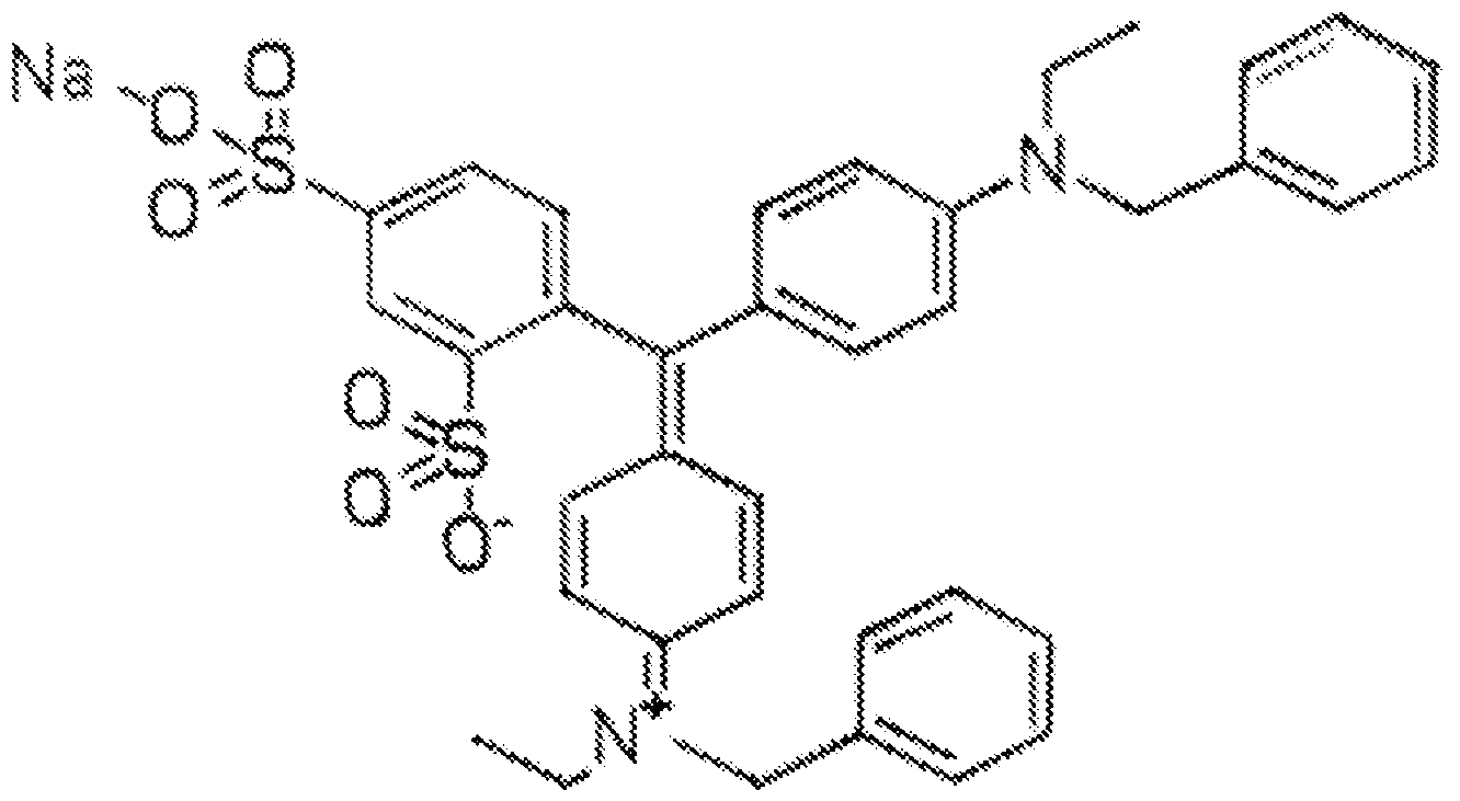
(commercially available as Acid Blue 7); and a phthalocyanine with a chemical structure of:

Direct Blue 199); and combinations thereof.
[0131] In an example of the detailing agent, the dye may be present in an amount ranging from about 1 wt% active to about 3 wt% active based on the total weight of the detailing agent. In another example of the detailing agent including a combination of dyes, one dye (e.g., the black dye) is present in an amount ranging from about 1.50 wt% active to about 1 .75 wt% active based on the total weight of the detailing agent, and the other dye (e.g., the cyan dye) is present in an amount ranging from about 0.25 wt% active to about 0.50 wt% active based on the total weight of the detailing agent.
[0132] The balance of the detailing agent is water. As such, the amount of water may vary depending upon the amounts of the other components that are included.
[0133] Coloring Agent
[0134] The 3D manufacturing method that involves the selective application of the fusing agent to pattern the layer of the build material composition may also involve the selective application of a coloring agent. The coloring agent may be used to impart color to the 3D object.
[0135] In these examples, the coloring agent is separate from the fusing agent. A coloring agent separate from the fusing agent may be desirable because the two agents can be applied separately, thus allowing control over where color is added. The coloring agent may be applied during printing (e.g., on the build material composition with the fusing agent) or after printing (e.g., on a 3D printed object) to impart a colored appearance to the 3D printed object.
[0136] The coloring agent may include a colorant, a co-solvent, and a balance of water. In some examples, the coloring agent of these components, and no other components. In still other examples, the coloring agent may further include additional components that aid in colorant dispersability and/or ink jettability. Some examples of additional coloring agent components include dispersant(s) (e.g., a water-soluble acrylic acid polymer (e.g., CARBOSPERSE® K7028 available from Lubrizol), water- soluble styrene-acrylic acid copolymers/resins (e.g., JONCRYL® 296, JONCRYL® 671 , JONCRYL® 678, JONCRYL® 680, JONCRYL® 683, JONCRYL® 690, etc. available from BASF Corp.), a high molecular weight block copolymer with pigment affinic groups (e.g., DISPERBYK®-190 available BYK Additives and Instruments), or water-soluble styrene-maleic anhydride copolymers/resins), humectant(s), surfactant(s), anti-kogation agent(s), and/or antimicrobial agent(s) (examples of which are described herein in reference to the fusing agent).
[0137] The coloring agent may be a black agent, a cyan agent, a magenta agent, or a yellow agent. As such, the colorant may be a black colorant, a cyan colorant, a magenta colorant, a yellow colorant, or a combination of colorants that together
achieve a black, cyan, magenta, or yellow color. While some examples have been provided, it is to be understood that other colored inks may also be used.
[0138] The colorant of the coloring agent may be any pigment or dye. When the coloring agent is a separate agent, the pigment or dye is to impart color, and is not meant to replace the energy absorber in the fusing agent. As such, the colorant may function as an energy absorber or as a partial energy absorber, or may not provide any anergy absorption.
[0139] An example of the pigment based colored ink may include from about 1 wt% to about 10 wt% of pigment(s), from about 10 wt% to about 30 wt% of co-solvent(s), from about 1 wt% to about 10 wt% of dispersant(s), 0.01 wt% to about 1 wt% of anti- kogation agent(s), from about 0.05 wt% to about 0.1 wt% anti-microbial agent(s), and a balance of water. An example of the dye based colored ink may include from about 1 wt% to about 7 wt% of dye(s), from about 10 wt% to about 30 wt% of co-solvent(s), from about 1 wt% to about 7 wt% of dispersant(s), from about 0.05 wt% to about 0.1 wt% antimicrobial agent(s), from 0.05 wt% to about 0.1 wt% of chelating agent(s), from about 0.005 wt% to about 0.2 wt% of buffer(s), and a balance of water.
[0140] Sets and Kits
[0141] The build material composition 22 disclosed herein may be part of a 3D printing kit with any example of the fusing agent (e.g., core, primer, and/or UV light) disclosed herein. In one example, the kit is a single fusing agent kit that includes the build material composition 22 and one of the fusing agents (e.g., the core fusing agent, the primer fusing agent, or the UV light fusing agent). In one example, the kit is a multi-fusing agent kit that includes the build material composition 22 and two or more of the fusing agents (e.g., the core fusing agent and the primer fusing agent).
[0142] Any example of the 3D printing kit may also be a multi-fluid kit, which includes one or more of the fusing agents, as well as the detailing agent and/or the coloring agent.
[0143] It is to be understood that the fluid(s) and the build material composition 22 of the 3D printing kits may be maintained separately until used together in examples of the 3D printing method disclosed herein. The fluid(s) and/or compositions may each
be contained in one or more containers prior to and during printing, but may be combined together during printing. The containers can be any type of a vessel (e.g., a reservoir), box, or receptacle made of any material.
[0144] Printing Methods
[0145] The build material composition 22 disclosed herein may be used in a variety of 3D printing techniques, including those that utilize a fusing agent or selective laser sintering (SLS). The 3D printing method generally includes spreading the build material composition 22 to form a build material layer, the build material composition including polyamide particles 20 present in an amount of at least 82 wt% based on a total weight of the build material composition 22; and a surface modified filler material 10 present in an amount ranging from about 2 wt% to about 18 wt% based on the total weight of the build material composition 22, the surface modified filler material 10 including an aramid fiber and an amino-terminated hyperbranched polymer attached to a surface of the aramid fiber, the amino-terminated hyperbranched polymer being selected from the group consisting of an amino-terminated hyperbranched polyamide and an amino-terminated hyperbranched polyamine; and coalescing at least some of the build material composition in the build material layer by: i) based on data derived from a digital 3D object model, selectively applying a fusing agent on at least a portion of the build material layer; and exposing the build material layer to electromagnetic radiation to coalesce the build material composition 22 in the at least the portion, thereby forming a layer of a 3D object; or ii) based on data derived from a digital 3D object model, selectively exposing the at least some of the build material composition 22 in the build material layer to a laser beam.
[0146] To form the 3D object, the method may be repeated. As such, the method may further include iteratively applying individual build material layers of the build material composition 22, and iteratively coalescing at least some of the build material composition 22 in each of the build material layers.
[0147] An example of the 3D object (i.e., 3D printed article) disclosed herein includes coalesced build material, which includes polyamide particles 20 present in an
amount of at least 80 wt% based on a total weight of the 3D printed article; and a filler material consisting of the surface modified aramid fibers 10.
[0148] Some examples of the 3D printed article also include the flow aid present in an amount up to 0.2 wt% based on the total weight of the 3D printed article, and/or any other build material composition additives set forth herein.
[0149] When the 3D printing technique utilized to generate the 3D printed article involves the selective application of the fusing agent, the 3D printed article also includes an energy absorber intermingled with the coalesced build material, wherein the energy absorber: exhibits absorption at least at some wavelengths within a range of from 100 nm to 4000 nm; or exhibits absorption at wavelengths ranging from 100 nm to 400 nm or 800 nm to 4000 nm and has transparency at wavelengths ranging from 400 nm to 780 nm. The amount of the energy absorber in the 3D printed article will depend upon the amount of the energy absorber in the fusing agent as well as the volume of the fusing agent that is applied to each of the layers of the build material composition.
[0150] The 3D printed article may also include the coloring agent applied on an exterior of the 3D printed article or incorporated into at least a portion of the coalesced build material, the coloring agent being selected from the group consisting of a black agent, a cyan agent, a magenta agent, and a yellow agent.
[0151] Printing Methods with Fusing Agent(s)
[0152] Different examples of the 3D printing method that utilize the fusing agent(s) are shown and described in reference to Fig. 3 and Fig. 4.
[0153] Prior to execution of any examples of the method, it is to be understood that a controller may access data stored in a data store pertaining to a 3D part/object that is to be printed. The data may include a digital model of the 3D part/object that is to be build, and additional data, for example, the number of layers of the build material composition that are to be formed, the locations at which any of the agents is/are to be deposited on each of the respective layers, etc. may be derived from this digital 3D object model.
[0154] Printing with one Fusing Agent
[0155] Referring now to Fig. 3, an example of a 3D printing method which utilizes one of the fusing agents is schematically depicted.
[0156] The method shown in Fig. 3 includes spreading the build material composition 22 to form a build material layer 24; based on a 3D object model, selectively applying a fusing agent (e.g., core fusing agent 26, primer fusing agent 26’, UV light fusing agent 26”) onto the build material layer 24, thereby forming a patterned portion 28; and exposing the build material layer 24 to electromagnetic radiation EMR to selectively coalesce the patterned portion 28 and form a 3D printed object layer 30. [0157] Prior to spreading, the method may further include applying the build material composition 22 to a build area platform 32 having an X-Y plane (at surface 34). In Fig. 3, the layer 24 of the build material composition 22 is formed on the build area platform 32. A printing system may be used to apply the build material composition 22. The printing system may include the build area platform 32, a build material supply 36 containing the build material composition 22, and a build material distributor 38.
[0158] The surface 34 of the build area platform 32 provides the X-Y plane for building the 3D printed object. The surface 34 receives the build material composition 22 from the build material supply 36. The build area platform 32 may be moved in the directions as denoted by the arrow 40, e.g., along the Z-axis, so that the build material composition 22 may be delivered to the build area platform 32 or to a previously formed layer. In an example, when the build material composition 22 is to be delivered, the build area platform 32 may be programmed to advance (e.g., downward) enough so that the build material distributor 38 can push the build material composition 22 onto the build area platform 32 to form a substantially uniform layer 24 of the build material composition 22 thereon. The build area platform 32 may also be returned to its original position, for example, when a new part is to be built.
[0159] The build material supply 36 may be a container, bed, or other surface that is to position the build material composition 22 between the build material distributor 38 and the build area platform 32. The build material supply 36 may include heaters so that the build material composition 22 is heated to a supply temperature ranging
from about 25°C to about 150°C. In these examples, the supply temperature may depend, in part, on the build material composition 22 used and/or the 3D printer used. As such, the range provided is one example, and higher or lower temperatures may be used.
[0160] The build material distributor 38 may be moved in the directions as denoted by the arrow 42, e.g., along the Y-axis, over the build material supply 36 and across the build area platform 32 to spread the layer 24 of the build material composition 22 over the build area platform 32. In this example, the spreading is performed in the Y- direction of the X-Y plane. The build material distributor 38 may also be returned to a position adjacent to the build material supply 36 following the spreading of the build material composition 22. The build material distributor 38 may be a blade (e.g., a doctor blade), a roller, a combination of a roller and a blade, and/or any other device capable of spreading the build material composition 22 over the build area platform 32. For instance, the build material distributor 38 may be a counter-rotating roller. In some examples, the build material supply 36 or a portion of the build material supply 36 may translate along with the build material distributor 38 such that build material composition 22 is delivered continuously to the build area platform 32 rather than being supplied from a single location at the side of the printing system as depicted in Fig. 3.
[0161] The build material supply 36 may supply the build material composition 22 into a position so that it is ready to be spread onto the build area platform 32. The build material distributor 38 may spread the supplied build material composition 22 onto the build area platform 32. The controller (not shown) may process “control build material supply” data, and in response, control the build material supply 36 to appropriately position the particles of the build material composition 22, and may process “control spreader” data, and in response, control the build material distributor 38 to spread the build material composition 22 over the build area platform 32 to form the layer 24. In Fig. 3, one build material layer 24 has been formed.
[0162] The layer 24 has a substantially uniform thickness across the build area platform 32. In an example, the build material layer 24 has a thickness ranging from about 50 pm to about 120 pm. In another example, the thickness of the build material
layer 24 ranges from about 30 pm to about 300 pm. It is to be understood that thinner or thicker layers may also be used. For example, the thickness of the build material layer 24 may range from about 20 pm to about 500 pm. The layer thickness may be about 2x (i.e. , 2 times) the average particle size (e.g., diameter) of the polyamide particles at a minimum for finer part definition. In some examples, the layer thickness may be about 1 ,2x the average diameter of the polyamide particles in the build material composition 22.
[0163] After the build material composition 22 has been applied and spread, and prior to further processing, the build material layer 24 may be exposed to heating. In an example, the heating temperature may be below the melting point of the polyamide particles 20 in the build material composition 22. As examples, the pre-heating temperature may range from about 10°C to about 150°C below the melting point of the polyamide particles 20. In an example, the pre-heating temperature ranges from about 50°C to about 170°C.
[0164] Pre-heating the layer 24 may be accomplished by using any suitable heat source that exposes all of the build material composition 22 in the layer 24 to the heat. Examples of the heat source include a thermal heat source (e.g., a heater (not shown) integrated into the build area platform 32 (which may include sidewalls)) or a radiation source 50.
[0165] After the layer 24 is formed, and in some instances is pre-heated, the fusing agent 26 or 26’ or 26” is selectively applied on at least some of the build material composition 22 in the layer 24 to form a patterned portion 28.
[0166] To form a layer 30 of a 3D printed object, at least a portion (e.g., patterned portion 28) of the layer 24 of the build material composition 22 is patterned with the fusing agent 26 or 26’ or 26”. Any of the core fusing agent 26, or the primer fusing agent 26’, or the UV light fusing agent 26” may be used. When it is desirable to form a white, colored, or slightly tinted object layer 30, the primer fusing agent 26’ or the UV light fusing agent 26” may be used to pattern the build material composition 22. The primer fusing agent 26’ or the UV light fusing agent 26” is clear or slightly tinted (depending upon the energy absorber used), and thus the resulting 3D printed object layer 30 may appear white, lightly colored (e.g., yellow), or the color of the build
material composition 22. When it is desirable to form a darker color or black object layer 30, the core fusing agent 26 may be used. The core fusing agent 26 is dark or black, and thus the resulting 3D printed object layer 30 may appear grey, black or another dark color. In other examples of the method, the core and primer fusing agents 26 and 26’ may be used to together to pattern different portions of a single build material layer 24. Color may also be added by using the coloring agent (not shown).
[0167] The volume of the fusing agent 26 or 26’ or 26” that is applied per unit of the build material composition 22 in the patterned portion 28 may be sufficient to absorb and convert enough electromagnetic radiation so that the build material composition 22 in the patterned portion 28 will coalesce/fuse. The volume of the fusing agent 26 or 26’ or 26” that is applied per unit of the build material composition 22 may depend, at least in part, on the energy absorber used, the energy absorber loading in the fusing agent 26 or 26’ or 26”, and the polyamide particles 20 in the build material composition 22.
[0168] The fusing agent 26 or 26’ or 26” may be dispensed from an applicator 44. The applicator 44 may include a thermal inkjet printhead, a piezoelectric printhead, a continuous inkjet printhead, etc., and the selective application of the fusing agent 26 or 26’ or 26” may be accomplished by thermal inkjet printing, piezo electric inkjet printing, continuous inkjet printing, etc. The controller may process data, and in response, control the applicator 44 to deposit the fusing agent 26 or 26’ or 26” onto the predetermined portion(s) 28 of the build material composition 22.
[0169] It is to be understood that the selective application of the fusing agent 26 or 26’ or 26” may be accomplished in a single printing pass or in multiple printing passes. In some examples, the fusing agent 26 or 26’ or 26” is selectively applied in a single printing pass. In some other examples, the fusing agent 26 or 26’ or 26” is selectively applied in multiple printing passes. In one of these examples, the number of printing passes ranging from 2 to 4. It may be desirable to apply the fusing agent 26 or 26’ or 26” in multiple printing passes to increase the amount, e.g., of the energy absorber that is applied to the build material composition 22, to avoid liquid splashing, to avoid displacement of the build material composition 22, etc.
[0170] In the example shown in Fig. 3, the detailing agent 46 is also selectively applied to the portion(s) 48 of the layer 24. The portion(s) 48 are not patterned with the fusing agent 26 or 26’ or 26” and thus are not to become part of the final 3D printed object layer 30. Thermal energy generated during radiation exposure may propagate into the surrounding portion(s) 48 that do not have the fusing agent 26 or 26’ or 26” applied thereto. The propagation of thermal energy may be inhibited, and thus the coalescence of the non-patterned build material portion(s) 48 may be prevented, when the detailing agent 46 is applied to these portion(s) 48.
[0171] The detailing agent 46 may also be dispensed from an applicator 44’. The applicator 44’ may include any of the inkjet printheads set forth herein. It is to be understood that the applicators 44, 44’ may be separate applicators or may be a single applicator with several individual cartridges for dispensing the respective agents 26 or 26’ or 26” and 46. The detailing agent 46 may also be selectively applied in a single printing pass or in multiple printing passes.
[0172] After the agents 26 or 26’ or 26” and 46 are selectively applied in the specific portion(s) 28 and 48 of the layer 24, the entire layer 24 of the build material composition 22 is exposed to electromagnetic radiation (shown as EMR in Fig. 3). [0173] The electromagnetic radiation is emitted from the radiation source 50. The length of time the electromagnetic radiation is applied for, or energy exposure time, may be dependent, for example, on one or more of: characteristics of the radiation source 50; characteristics of the build material composition 22; and/or characteristics of the fusing agent 26 or 26’ or 26”.
[0174] It is to be understood that the electromagnetic radiation exposure may be accomplished in a single radiation event or in multiple radiation events. In an example, the exposing of the build material composition 22 is accomplished in multiple radiation events. In a specific example, the number of radiation events ranges from 3 to 8. In still another specific example, the exposure of the build material composition 22 to electromagnetic radiation may be accomplished in 3 radiation events. It may be desirable to expose the build material composition 22 to electromagnetic radiation in multiple radiation events to counteract a cooling effect that may be brought on by the amount of the agents 26 or 26’ and 46 that is applied to the build material layer 24.
Additionally, it may be desirable to expose the build material composition 22 to electromagnetic radiation in multiple radiation events to sufficiently elevate the temperature of the build material composition 22 in the portion(s) 26, 48, without over heating the build material composition 22 in the non-patterned portion(s) 48.
[0175] The fusing agent 26 or 26’ or 26” enhances the absorption of the radiation, converts the absorbed radiation to thermal energy, and promotes the transfer of the thermal heat to the build material composition 22 in contact therewith. In an example, the fusing agent 26 or 26’ or 26” sufficiently elevates the temperature of the build material composition 22 in the portion 28 to a temperature above the melting point of the polyamide particles 20, allowing coalescing/fusing (e.g., thermal merging, melting, binding, etc.) of the build material composition 22 to take place. The application of the electromagnetic radiation forms the 3D printed object layer 30.
[0176] In some examples, the electromagnetic radiation has a wavelength ranging from 100 nm to 400 nm, from 400 nm to 4000 nm, or from 800 nm to 1400 nm, or from 800 nm to 1200 nm. The radiation used will depend upon the fusing agent 26 or 26’ or 26” that is used. Radiation having wavelengths within the appropriate ranges may be absorbed by the fusing agent 26 or 26’ or 26” and may heat the build material composition 22 in contact therewith, and may not be absorbed by the non-patterned build material composition 22 in portion(s) 48.
[0177] After the 3D printed object layer 30 is formed, additional layer(s) may be formed thereon to create an example of the 3D printed polyamide object. To form the next layer, additional build material composition 22 may be applied on the layer 30. The fusing agent 26 or 26’ or 26” is then selectively applied on at least a portion of the additional build material composition 22, according to data derived from the 3D object model. The detailing agent 46 may be applied in any area of the additional build material composition 22 where coalescence is not desirable. After the agent(s) 26 or 26’ or 26” and 46 is/are applied, the entire layer of the additional build material composition 22 is exposed to electromagnetic radiation in the manner described herein. The application of additional build material composition 22, the selective application of the agent(s) 26 or 26’ or 26” and 46, and the electromagnetic radiation
exposure may be repeated a predetermined number of cycles to form the final 3D printed polyamide object in accordance with the 3D object model.
[0178] Printing with the Core and Primer Fusing Agents
[0179] Referring now to Fig. 4, an example of the 3D printing method with both of the fusing agents 26 and 26’ is depicted.
[0180] The method shown in Fig. 4 includes applying a build material composition 22 to form a build material layer 24; based on data derived from a digital 3D object model, selectively applying a core fusing agent 26 onto the build material layer 24, thereby forming a first patterned portion 28A; based on the data derived from the 3D object model, selectively applying a primer fusing agent 26’ onto the build material layer 24, thereby forming a second patterned portion 28B adjacent to the first patterned portion 28A; and exposing the build material layer 24 to electromagnetic radiation EMR to selectively coalesce the patterned portions 28A and 28B and form a 3D printed object layer 30’.
[0181] In Fig. 4, one layer 24 of the build material composition 22 is applied on the build area platform 32 as described in reference to Fig. 2. After the build material composition 22 has been applied, and prior to further processing, the build material layer 24 may be exposed to pre-heating as described in reference to Fig. 2.
[0182] In this example of the 3D printing method, the core fusing agent 26 is selectively applied on at least some of the build material composition 22 in the layer 24 to form a first patterned portion 28A; and the primer fusing agent(s) 26’ is selectively applied on at least some of the build material composition 22 in the layer 24 to form second patterned portion(s) 28B that are adjacent to the first patterned portion(s) 28A. In one example, the first patterned portion 28A (patterned with the core fusing agent 26) may be located at an interior portion of the build material layer 24 to impart mechanical strength, and the second patterned portion 28B (patterned with the primer fusing agent 26’) may be located at an exterior portion of the build material layer 24 to mask the color of the first patterned portion 28A.
[0183] The volume of the core fusing agent 26 that is applied per unit of the build material composition 22 in the first patterned portion 28A may be sufficient to absorb
and convert enough electromagnetic radiation so that the build material composition 22 in the patterned portion 28A will coalesce/fuse.
[0184] The volume of the primer fusing agent 26’ that is applied per unit of the build material composition 22 in the second patterned portion 28B may be sufficient to absorb and convert enough electromagnetic radiation so that the build material composition 22 in the second patterned portion 28B will coalesce/fuse.
[0185] In the example shown in Fig. 4, the detailing agent 46 is also selectively applied to the portion(s) 48 of the layer 24. The portion(s) 48 are not patterned with the fusing agent 26 or 26’ and thus are not to become part of the final 3D printed object layer 30’.
[0186] After the agents 26, 26’, and 46 are selectively applied in the specific portion(s) 28A, 28B, and 46 of the layer 24, the entire layer 24 of the build material composition 22 is exposed to electromagnetic radiation (shown as EMR in Fig. 4). Radiation exposure may be accomplished as described in reference to Fig. 3.
[0187] In this example, the respective fusing agents 26 and 26’ enhance the absorption of the radiation, convert the absorbed radiation to thermal energy, and promote the transfer of the thermal heat to the build material composition 22 in contact therewith. In an example, the fusing agents 26 and 26’ sufficiently elevate the temperature of the build material composition 22 in the respective portions 28A, 28B to a temperature above the melting point of the polyamide particles 20, allowing coalescing/fusing (e.g., thermal merging, melting, binding, etc.) of the build material composition 22 to take place. The application of the electromagnetic radiation forms the 3D printed object layer 30’, which, in this example, includes a core portion 52 and primer portions 54 at opposed ends of the core portion 52.
[0188] Fig. 4 illustrates one example of how the core fusing agent 26 and the primer fusing agent 26’ may be used together to pattern a single build material layer 24 and form one layer 30’ of the 3D printed object. The core fusing agent 26 and the primer fusing agent 26’ may be used to respectively pattern core portions (similar to core portion 52) and primer portions (similar to primer portions 54) in one or more additional layers 24 of the build material composition 22. The core fusing agent 26 can impart strength to the core of the 3D printed object, while the primer fusing agent
26’ enables white or a color to be exhibited at the exterior of the 3D printed object. In an example, the core fusing agent 26 can be applied on multiple layers of the build material composition 22 to pattern and ultimately form an inner core portion of the 3D printed object, and the primer fusing agent 26’ can be applied on multiple layers of the build material composition 22 to pattern and ultimately form outermost primer portions of the 3D printed object. In one example, the outermost primer portions surround the inner core portion. After each build material layer 24 is patterned with the agent(s) 26, 26’, electromagnetic radiation may be applied to solidify the respective patterned build material layers.
[0189] In any of the example 3D printing methods that utilize the fusing agent(s) 26, 26’, 26”, the coloring agent (not shown) may also be applied with the primer fusing agent 26’ or the UV light fusing agent 26” to generate color at the exterior surfaces of the 3D printed object. In these examples, the colorant of the coloring agent becomes embedded throughout the coalesced/fused build material composition wherever it is applied. In an example, the coloring agent may be applied with the primer fusing agent 26’ on the portions of the build material layers that form the primer portions. Since the primer fusing agent 26’ is clear or slightly tinted and the build material composition 12 is white or off-white, the color of the coloring agent will be the color of the resulting primer portions. Similarly, since the UV light fusing agent 26” is clear or slightly tinted and the build material composition 12 is white or off-white, the coloring agent may be used with this fusing agent 26” to impart color at desirable portions of the resulting 3D printed object.
[0190] When core and primer portions are formed and the coloring agent is used, it is to be understood that some of the primer portions directly adjacent to the core portions may be left uncolored. In this example, the uncolored primer portions are white or slightly tinted, and may function as intermediate layers that help to form a mask over the black (or dark colored) core layers. The presence of uncolored primer portions between core portions and primer portions that are colored with the coloring agent may help to optically isolate the core layers.
[0191] While several variations of the method have been described, it is to be understood that any of the fusing agents 26, 26’, 26” may be used to form any desirable 3D printed object.
[0192] Additionally, in the examples disclosed herein that utilize a fusing agent 26, 26, 26’, 26”, the 3D printed object may be printed in any orientation with respect to the X-Y plane of the build area platform 32, and thus with respect to the layers 24 of the build material composition 22. For example, the 3D printed object can be printed from bottom to top in the Z-direction, or at an inverted orientation (e.g., from top to bottom) in the Z-direction. For another example, the 3D printed object can be printed at an angle or on its side. The orientation of the build within the build material composition 22 can be selected in advance or even by the user at the time of printing, for example. [0193] It may be desirable to print the 3D object in the spreading direction of the build material composition 22. When an object is printed in a particular direction (e.g., X-, Y-, or Z-direction), it is meant that a load-bearing direction a 3D object being printed extends along the spreading direction. As such, when the build material composition 22 is spread in the Y-direction, it is also desirable that the length of the 3D object being printed also extend along the Y-direction. In this particular example, the 3D object may be printed from bottom to top in the Z-direction, but the load-bearing direction of the 3D object extends in the Y-direction (or the X-direction if that corresponds to the spreading direction).
[0194] Printing with Selective Laser Sintering
[0195] In other examples, the 3D printing process may involve Selective Laser Sintering (SLS). In these examples, the build material composition 22 may be spread across the surface 34 of the build area platform 32 as described herein in reference to Fig. 3.
[0196] Portion(s) of the uniformly spread layer 24 of the build material composition 22 is/are then exposed to a laser beam of high energy density. The laser spot scans the surface of the layer 24 of the spread build material composition 22, and emits a narrow energy beam in portion(s) that are to become part of the 3D printed object. The narrow beam heats the exposed polyamide particles in the build material composition 22 such that they coalesce. The laser is moved in the X- and/or Y-
direction to heat and coalesce the portion(s) of the build material composition 22 in a given layer 24. After one layer 24 is printed, an additional layer of the build material composition 22 is applied and the laser exposure is repeated in a desired pattern. [0197] The stacked coalesced layers produce the final 3D printed object (i.e. , each subsequent laser-patterned layer is formed on top of the previous one).
[0198] In addition to the 3D printing methods described herein, the build material composition 22 can be used other powder bed fusion technologies, injection molding, material extrusion, vat photopolymerization, and laminated object manufacturing. [0199] To further illustrate the present disclosure, an example is given herein. It is to be understood that this example is provided for illustrative purposes and is not to be construed as limiting the scope of the present disclosure.
EXAMPLE
[0200] Fiber Preparation
[0201 ] Bare (untreated) aramid fibers and plasma treated aramid fibers were obtained from Tech-in Materials Co. Ltd., China. The plasma treated aramid fibers had been treated with a mixture of two types of gases, namely a fluoride gas and an alcohol vapor. Both the bare aramid fibers and the plasma treated aramid fibers had an average length of 0.5 mm and an average width ranging from about 18 pm to 22 pm. The bare (untreated) aramid fibers were used as a first comparative example and some of the plasma treated aramid fibers were used as a second comparative example.
[0202] An aqueous solution containing amino-terminated hyperbranched polyamide was prepared. The amino-terminated hyperbranched polyamide had an amino-group content ranging from 12 mol/mol to about 16 mol/mol and was obtained from Wuhan Hyperbranched Polymer Science & Technology Co. Ltd., China. The aqueous solution was prepared by dissolving 16 grams of the HBA in 400 mL of deionized water. The aqueous solution containing the HBA was exposed to Fourier-transform infrared spectroscopy. The results are shown in Fig. 5. The HBA exhibited characteristic absorption peaks at 3277 cm'1 (s, N-H), 2930 cm'1 and 2826 (s, C-H), 1641 cm'1 (s,
C=O-N; b, N-H), and 1557 cm'1 (b, C-N), indicating that the structure of the HBA may be that shown in Fig. 2A.
[0203] Some of the plasma treated aramid fibers were then exposed to the aqueous solution containing the HBA. Specifically, 30 grams of the plasma treated aramid fibers were added to the aqueous solution containing the HBA. The mixture was continuously stirred at about 60°C for about 1 hour, and then was filtered and thoroughly washed with deionized water until the pH of the mixture was around 7. The collected surface treated fibers were then dried in an oven at 60°C for about 48 hours. In this example, the plasma and HPA surface treated aramid fibers are referred to as the example fibers.
[0204] As mentioned, the bare aramid fibers were used as comparative/control examples. The bare aramid fibers were dispersed in deionized water and the dispersion was continuously stirred at about 60°C for about 1 hour. The dispersion was filtered and thoroughly washed with deionized water. The collected bare fibers were then dried in an oven at 60°C for about 48 hours. In this example, the bare aramid fibers are referred to as the comparative example 1 fibers.
[0205] Also as mentioned, some of the plasma treated fibers were used as another comparative/control example. The plasma treated aramid fibers were dispersed in deionized water and the dispersion was continuously stirred at about 60°C for about 1 hour. The dispersion was then filtered and thoroughly washed with deionized water. The collected plasma treated fibers were then dried in an oven at 60°C for about 48 hours. In this example, the plasma treated aramid fibers are referred to as the comparative example 2 fibers.
[0206] Morphological Analysis of the Example and Comparative Fibers
[0207] The example fibers (plasma and HPA surface treated aramid fibers), the comparative example 1 fibers (bare aramid fibers), and the comparative example 2 fibers (plasma treated aramid fibers) were characterized using a scanning electron microscope (SEM) and an atomic force microscope (AFM). The SEM and AFM results for i) the example fibers are respectively shown in Fig. 6A and Fig. 6B, ii) the comparative example 1 fibers are respectively shown in Fig. 6C and Fig. 6D, and iii) the comparative example 2 fibers are respectively shown in Fig. 6E and Fig. 6F. The
SME images revealed that the surfaces of the comparative example 1 and 2 fibers were both relatively smooth (Fig. 6C and Fig. 6E), while the surface of the example fibers was rough (Fig. 6A). The example fiber surfaces also appeared to have some attached fragments (see Fig. 6A). It was noted that the example fibers were not damaged by the surface treatment, which is desirable for preserving the mechanical properties of the fibers. In addition, the SEM observations (Fig. 6A) revealed that no significant variation in fiber diameter was introduced after the chemical modification. Similarly, from the AFM mapping results (Fig. 6B and Fig. 6D), the comparative example 1 fibers and the comparative example 2 fibers had smooth surfaces with average surface roughness (Ra) of 5.1 nm and 7.0 nm, respectively. The surface of the example fibers was significantly changed after plasma treatment and HBP coating, yielding a conspicuous variation in its surface morphology and an average surface roughness of 22.9 nm.
[0208] Chemical Composition Analysis of the Example and Comparative Fibers [0209] X-ray photoelectron spectroscopy (XPS) with high surface sensitivity was used to detect the elements on the surface of each of the example fibers, the comparative example 1 fibers, and the comparative example 2 fibers. Fig. 7A shows the XPS wide-scan spectra of each of the example fibers, the comparative example 1 fibers, and the comparative example 2 fibers. The results for the comparative example 2 fibers illustrated that the plasma treatment reduced the atomic ratio of carbon and nitrogen on the fiber surface by introducing fluorine and oxygen. More specifically, when compared with the comparative example 1 fibers, a characteristic F 1s peak and a stronger O 1 s peak were respectively observed at 685 eV and 531 eV in the comparative example 2 fibers, indicating that the plasma treatment resulted in fluorination and oxidation to achieve a more hydrophilic and activated fiber surface. [0210] Because the FTIR analysis of the HBP identified many nitrogen-containing groups, including 1 ° (terminated amino), 2°, and 3° amines and amides, a high- resolution scan of the N 1s peaks was performed. These results are shown in Fig. 7B. Comparing the results from Fig. 7A for the comparative example 1 fibers with the chemically modified example fibers, the N 1s peak of the fiber surface shifted from 400.3 eV to 399.3 eV due to the increasing electron density. The N 1s peak of the
example fibers in Fig. 7A can be resolved into two peaks, as shown in Fig. 7B, at 400.1 eV and 399.2 eV, which are assigned to the amide and the additional amines, respectively. These results confirmed the presence of HBP on the surface of the example fibers. Because the example fibers were rinsed to remove redundant or weakly bonded HBP molecules, the results in Fig. 7A and 7B support the conclusion that the terminal amino groups of the HBP molecules are bonded with the hydrophilic groups generated by the plasma treatment.
[0211] Interfacial Shear Strength
[0212] The property of interfacial shear strength (IFSS) may be used to evaluate the reinforcement effect of the fiber reinforcement/filler materials on build material compositions containing the fiber reinforcement materials and polyamide particles. When the interfacial adhesion between the fiber reinforcement materials and the polymer particles is at a desirable level, the load from the polymer particles can be effectively transferred to the fiber reinforcement materials, which can lead to a reduction in the stress concentration and an enhancement of the mechanical performance.
[0213] A single-fiber microbond pull-out test was performed to evaluate the IFSS at the interfaces between the respective fibers (i.e., the example fibers, comparative example 1 fibers, and comparative example 2 fibers) and polyamide 12 particles (High Reusability PA 12 powder from HP Inc). For the single-fiber microbond pull-out test, a respective one of the example fibers, the comparative example 1 fibers, and the comparative example 2 fibers was used. Each of the fibers was a long, continuous fiber. Microballs of melted polyamide 12 particles were attached along the length of the respective fibers. Specifically, the polyamide 12 particles were placed in a basket above the fiber in a furnace equipped in the testing machine. After raising the temperature to the melting point of polyamide 12, the basket with molten polyamide 12 was moved downwards to touch the fiber and then back to its original position, allowing a small fraction of molten polyamide 12 to stick to the fiber. A microdroplet was formed by surface tension minimizing the surface energy, and then a solidified microball was obtained after the furnace was cooled down to the room temperature.
[0214] The fibers were respectively positioned so that the microball attached to the fiber was located in a gap between upper and lower blades of the testing machine. The fiber was pulled by an attached load cell to push the microball against the blades until it became debonded from the fiber. The resulting IFSS (T) was calculated using the following equation:
 where F is the maximum pull-out load, D is the diameter of the fiber, and L is the embedded length of the microball.
[0215] Fig. 8 illustrates the IFSS results for the example fibers, the comparative example 1 fibers, and the comparative example 2 fibers. The IFSS was 25.1 MPa for the comparative example 1 fibers, which had the inert and smooth surface. After plasma treatment, the surface of the comparative example 2 fibers became hydrophilic, and the IFSS increased to 32.2 MPa. The IFSS was further improved to 36.4 for the example fibers, indicating better interlocking and bonding of the surface modified fibers with the polyamide particles.
[0216] Build Material Composition Preparation
[0217] All of the fibers (example fibers, comparative example 1 fibers, and comparative example 2 fibers) were used to prepare respective build material compositions (example BMC, comparative example 1 BMC, and comparative example 2 BMC). Different amounts of the example fibers were used to prepare four different build material compositions. Each of the build material compositions included polyamide particles (High Reusability PA 12 powder from HP Inc.). A control build material composition included polyamide particles without any fibers.
[0218] The build material compositions were prepared by mixing the polyamide particles and the respective aramid fibers (if used) in a mechanical mixer (Inversina 2L, Bioengineering AG, Switzerland) at a rotation speed of 60 rpm for about 4 hours. Prior to mixing, all of the fibers were respectively sieved through a strainer having a 1 mm mesh size. The various BMCs are shown in Table 1 .
Table 1
Table 1 - Build material Compositions

[0219] Powder Flowability
[0220] Powder flowability is a property of a build material composition that contributes to its recoatability (e.g., non-patterned build material that is collected, mixed with fresh build material composition, and is used again in a 3D printing process), as well as to printed object quality.
[0221 ] The dynamic avalanche angle indicates particle cohesiveness during flow, and a high avalanche angle may lead to undesirable cohesion, resulting in high void fraction of the product. The dynamic avalanche angle was determined for build material compositions Ex. BMC-10 (with 10 wt% of the example fibers), Comp. Ex. 1 BMC (with 10 wt% of comparative example 1 fibers), and Comp. Ex. 2 BMC (with 10 wt% of comparative example 2 fibers). The dynamic avalanche angle was measured from the center point on the powder edge (the horizontal reference line) to the maximum height of free powder surface just before an avalanche started as the powder was rotated in a drum.
[0222] Histograms of avalanche angle distributions (fitted by Gaussian functions) for Ex. BMC-10, Comp. Ex. 1 BMC, and Comp. Ex. 2 BMC (each containing 10 wt% of the respective fibers) are respectively shown in Fig. 9A, Fig. 9B, and Fig. 9C. The average avalanche angle for Ex. BMC-10 was 57.4°, for Comp. Ex. 1 BMC was 56.1 °, and Comp. Ex. 2 BMC was 58.3°. These results indicate that there are no significant change
between the example and comparative example BMCs, and thus suggest that the surface modification disclosed herein had little effect on the powder flowability. The results were also consistent with the avalanche angles, ranging from 40° to 60°, reported for other polyamide build material compositions.
[0223] Three-Dimensional Printing
[0224] All of the build material compositions shown in Table 1 were used to print dog bone shaped 3D objects. All of the dog bone shaped 3D objects were printed on a small testbed 3D printer with the build material composition being spread in the Y- direction to layer thicknesses of 80 pm. A fusing agent (that included carbon black as the energy absorber) was printed in a single pass in the X-direction. After the fusing agent was dispensed, the entire build area platform was exposed to near-infrared energy. The process was repeated until the entire object was formed. Each of the example and comparative example build materials was printed in the X-direction and the Y-direction. All of the dog bone shaped 3D objects were allowed to cool to room temperature, and then were cleaned using bead blasting.
[0225] 3D Object Mechanical Properties
[0226] The mechanical properties of the dog bone shaped 3D objects printed in the X- and Y-directions were measured by tensile tests in accordance with the American Society for Testing and Materials (ASTM) D638 Type V standard and 3-point bending tests at a test speed of 1 mm/min. The results are shown in Table 2. The 3D objects are identified by the build material composition that was used to generate the 3D object.
Table 2 - Mechanical Properties - X- and Y-directions

[0227] Fig. 10 shows the stress-strain curves of the Control Object (0 wt% fibers) and the Example Objects formed with the example BCMs (containing 4 wt%, 8 wt%, 10 wt%, and 12 wt% example fibers) printed in the Y-direction. With the increase in the fiber fraction, the ultimate tensile strength (UTS) first increased and then reduced, resulting in a maximum UTS of 73.4 MPa for Ex. Object C (containing 10 wt% of the example fibers). This was a 55% increase compared with that of the Control Object formed with the control BMC (containing neat polyamide particles and no fibers). The decrease in the UTS may have been cause by porosity, which may be been the result of poor flowability. As shown in Table 2, the Young’s modulus of the Example Objects had a similar trend as the UTS, with a maximum value of about 4.2 GPa for Ex. Object C (containing 10 wt% of the example fibers). Also as shown in Table 2, the elongation at break decreased from 63.3% (control 3D object) to 4.8% (Ex. Object D, 12 wt% example fibers) with increasing the fiber fraction, as the increment in strength and modulus may be gained with increasing brittleness.
[0228] Fig. 11 illustrates the effect of fiber fraction on the UTS of the Example Objects printed in two directions. The UTS of the Example Objects printed in the X- direction slightly increased and then decreased. The discrepancy of UTS in the different directions, especially for Ex. Objects B, C, and D (with higher fiber fractions), revealed the anisotropy of the BMCs caused by the fiber alignment in the Y-direction. Fibers with large aspect ratios are influenced by the roller-induced shear force, and thus the preferred orientation for these fibers is along the spreading direction. The fiber alignment effectively enhances the mechanical performance in the spreading direction, but inevitably induces the decrease of the mechanical performance in the other direction. Ex. Object B exhibited suitable UTS in both directions, as the UTS of Ex. Object B printed in the X-direction (45.5 MPa) remained roughly that of Control Object (45.8 MPa).
[0229] Fig. 12 is a graph comparing the UTS of the Control Object, Comp. Objects 1 and 2 (each with 10 wt% of the respective comparative fibers), and Ex. Object C (with 10 wt% of the example fibers). The UTS of Ex. Object C exceeded the UTS of both Comp. Object 1 and Comp. Object 2 in both the X- and Y- directions. Therefore, the surface modification of HBP not only enables significant enhancement in strength of the Example Objects in the spreading direction, but also effectively alleviates the performance degrading in the perpendicular direction. This could be due to the increase in interfacial adhesion between the example fibers and the polyamide particles (Fig. 8).
[0230] The different interfacial adhesions correlate with different fracture morphologies. Comp. Objects 1 and 2 and Ex. Object C (each with 10 wt% of the respective fibers) were fractured in the gauge section (the skinny portion of the dog bone where deformation and failure can occur more easily), and a scanning electron micrograph (SEM) image of the cross-section of the break was taken. The SEM images illustrating the fracture morphologies are shown in Fig. 13A (Ex. Object C printed in the Y-direction), Fig. 13B (Comp. Object 1 printed in the Y-direction), and Fig. 13C (Comp. Object 2 printed in the Y-direction). In each of the figures, the fibers are oriented perpendicular to the fracture surfaces, and there are some holes left by the pull-out fibers. The dashed circles in Fig. 13A clearly illustrate fiber fractures in the
form of fibrils, which may have been created by the fracture of the fiber, suggesting the high interfacial adhesion between the fiber and polyamide particles. These fibrils were not observed for either of the Comp. Objects. Therefore, the surface modified fibers gave rise to enhanced strength by stopping crack propagation through energy absorbing processes, such as fiber debonding, fiber pull-out from the polyamide matrix, and fiber fracture.
[0231] Ex. Object C printed along the Y-direction reached a specific strength of 71.2 kN m/kg.
[0232] It is to be understood that the ranges provided herein include the stated range and any value or sub-range within the stated range, as if the value(s) or subrange^) within the stated range were explicitly recited. For example, a range from about 2 wt% to about 18 wt%, should be interpreted to include not only the explicitly recited limits of from about 2 wt% to about 18 wt%, but also to include individual values, such as about 2.75 wt%, 8 wt%, 14 wt%, 15.5 wt%, etc., and sub-ranges, such as from about 5 wt% active to about 15 wt% active, from about 3 wt% active to about 17 wt% active, from about 2 wt% active to about 14 wt% active, etc.
[0233] Furthermore, when “about” is utilized to describe a value, this is meant to encompass minor variations (up to +/- 10%) from the stated value.
[0234] Reference throughout the specification to “one example”, “another example”, “an example”, and so forth, means that a particular element (e.g., feature, structure, and/or characteristic) described in connection with the example is included in at least one example described herein, and may or may not be present in other examples. In addition, it is to be understood that the described elements for any example may be combined in any suitable manner in the various examples unless the context clearly dictates otherwise.
[0235] In describing and claiming the examples disclosed herein, the singular forms “a”, “an”, and “the” include plural referents unless the context clearly dictates otherwise.
[0236] While several examples have been described in detail, it is to be understood that the disclosed examples may be modified. Therefore, the foregoing description is to be considered non-limiting.
Claims
1 . A method for preparing a surface modified filler material, comprising: treating aramid fibers to a hydrophilic treatment to generate treated aramid fibers; exposing the treated aramid fibers to an aqueous solution, containing an aminoterminated hyperbranched polymer selected from the group consisting of an aminoterminated hyperbranched polyamide and an amino-terminated hyperbranched polyamine, for a predetermined time and at a predetermined temperature, thereby generating surface modified aramid fibers; and drying the surface modified aramid fibers.
2. The method as defined in claim 1 , wherein the aqueous solution includes from about 1 wt% to about 10 wt%, based on a total weight of the aqueous solution, of the amino-terminated hyperbranched polymer.
3. The method as defined in claim 1 , wherein: the predetermined time ranges from about 0.5 hours to about 5 hours; and the predetermined temperature ranges from about 40°C to about 70°C.
4. The method as defined in claim 1 , wherein the exposing involves: submerging the treated aramid fibers in the aqueous solution; and mixing the aqueous solution containing the treated aramid fibers.
5. The method as defined in claim 1 , wherein the drying involves exposing the surface modified aramid fibers to a temperature ranging from about 18°C to about 80°C for a time ranging from about 2 days to about 5 days.
6. The method as defined in claim 1 , wherein the amino-terminated hyperbranched polymer has a terminal amino group content ranging from about 3 moles per mole of the amino-terminated hyperbranched polymer to about 20 moles per mole of the amino-terminated hyperbranched polymer.
73
7. A three-dimensional (3D) printing build material composition, comprising: polyamide particles present in an amount of at least 82 wt% based on a total weight of the build material composition; and a surface modified filler material present in an amount ranging from about 2 wt% to about 18 wt% based on the total weight of the build material composition, the surface modified filler material including: an aramid fiber; and an amino-terminated hyperbranched polymer attached to a surface of the aramid fiber, the amino-terminated hyperbranched polymer being selected from the group consisting of an amino-terminated hyperbranched polyamide and an amino-terminated hyperbranched polyamine.
8. The 3D printing build material composition as defined in claim 7 wherein the amino-terminated hyperbranched polymer has a terminal amino group content ranging from about 3 moles per mole of the amino-terminated hyperbranched polymer to about 20 moles per mole of the amino-terminated hyperbranched polymer.
9. The 3D printing build material composition as defined in claim 7 wherein the aramid fiber is plasma treated or acid treated.
10. The 3D printing build material composition as defined in claim 7, further comprising a flow aid present in an amount up to 0.2 wt% based on the total weight of the build material composition.
11 . A three-dimensional (3D) printing method, comprising: spreading a build material composition to form a build material layer, the build material composition including: polyamide particles present in an amount of at least 82 wt% based on a total weight of the build material composition; and
74 a surface modified filler material present in an amount ranging from about 2 wt% to about 18 wt% based on the total weight of the build material composition, the surface modified filler material including: an aramid fiber; and an amino-terminated hyperbranched polymer attached to a surface of the aramid fiber, the amino-terminated hyperbranched polymer being selected from the group consisting of an amino-terminated hyperbranched polyamide and an amino-terminated hyperbranched polyamine; and coalescing at least some of the build material composition in the build material layer by: i) based on data derived from a digital 3D object model, selectively applying a fusing agent on at least a portion of the build material layer; and exposing the build material layer to electromagnetic radiation to coalesce the build material composition in the at least the portion, thereby forming a layer of a 3D object; or ii) based on data derived from a digital 3D object model, selectively exposing the at least some of the build material composition in the build material layer to a laser beam.
12. The method as defined in claim 11 , wherein prior to spreading, the method further comprises applying the build material composition to a build area platform having an X-Y plane.
13. The method as defined in claim 12, wherein the spreading is performed in a Y-direction of the X-Y plane.
14. The method as defined in claim 13, wherein a load-bearing direction of a 3D object being printed extends along the Y-direction.
75
15. The method as defined in claim 11 , further comprising: iteratively applying individual build material layers of the build material composition; and iteratively coalescing at least some of the build material composition in each of the build material layers.
Priority Applications (1)
| Application Number | Priority Date | Filing Date | Title |
|---|---|---|---|
| PCT/US2021/060871 WO2023096648A1 (en) | 2021-11-24 | 2021-11-24 | Preparation of surface modified aramid fibers |
Applications Claiming Priority (1)
| Application Number | Priority Date | Filing Date | Title |
|---|---|---|---|
| PCT/US2021/060871 WO2023096648A1 (en) | 2021-11-24 | 2021-11-24 | Preparation of surface modified aramid fibers |
Publications (1)
| Publication Number | Publication Date |
|---|---|
| WO2023096648A1 true WO2023096648A1 (en) | 2023-06-01 |
Family
ID=86540156
Family Applications (1)
| Application Number | Title | Priority Date | Filing Date |
|---|---|---|---|
| PCT/US2021/060871 Ceased WO2023096648A1 (en) | 2021-11-24 | 2021-11-24 | Preparation of surface modified aramid fibers |
Country Status (1)
| Country | Link |
|---|---|
| WO (1) | WO2023096648A1 (en) |
Citations (6)
| Publication number | Priority date | Publication date | Assignee | Title |
|---|---|---|---|---|
| SU1048008A1 (en) * | 1982-04-02 | 1983-10-15 | Московский авиационный технологический институт им.К.Э.Циолковского | Method of modifying fibres based on aromatic polyamides |
| CN102516570A (en) * | 2011-10-21 | 2012-06-27 | 苏州大学 | Aramid fiber-reinforced rein-based composite material and preparation method thereof |
| CN103031708A (en) * | 2012-07-12 | 2013-04-10 | 山东理工大学 | Method for improving surface activity of aramid fiber |
| CN103194898A (en) * | 2013-03-27 | 2013-07-10 | 中国科学院长春应用化学研究所 | Surface modified aramid fiber, surface modification method thereof and static sealing material |
| US20200398484A1 (en) * | 2018-03-09 | 2020-12-24 | Hewlett-Packard Development Company, L.P. | Three-dimensional printing |
| US11104819B2 (en) * | 2018-03-21 | 2021-08-31 | Hewlett-Packard Development Company, L.P. | Three-dimensional printing |
-
2021
- 2021-11-24 WO PCT/US2021/060871 patent/WO2023096648A1/en not_active Ceased
Patent Citations (6)
| Publication number | Priority date | Publication date | Assignee | Title |
|---|---|---|---|---|
| SU1048008A1 (en) * | 1982-04-02 | 1983-10-15 | Московский авиационный технологический институт им.К.Э.Циолковского | Method of modifying fibres based on aromatic polyamides |
| CN102516570A (en) * | 2011-10-21 | 2012-06-27 | 苏州大学 | Aramid fiber-reinforced rein-based composite material and preparation method thereof |
| CN103031708A (en) * | 2012-07-12 | 2013-04-10 | 山东理工大学 | Method for improving surface activity of aramid fiber |
| CN103194898A (en) * | 2013-03-27 | 2013-07-10 | 中国科学院长春应用化学研究所 | Surface modified aramid fiber, surface modification method thereof and static sealing material |
| US20200398484A1 (en) * | 2018-03-09 | 2020-12-24 | Hewlett-Packard Development Company, L.P. | Three-dimensional printing |
| US11104819B2 (en) * | 2018-03-21 | 2021-08-31 | Hewlett-Packard Development Company, L.P. | Three-dimensional printing |
Similar Documents
| Publication | Publication Date | Title |
|---|---|---|
| US12466127B2 (en) | Multi-fluid kit for three-dimensional (3D) printing, and three-dimensional printing | |
| WO2019182614A1 (en) | Three-dimensional printing | |
| EP3986696B1 (en) | Three-dimensional printing | |
| US12187873B2 (en) | Three-dimensional printing | |
| US20240025113A1 (en) | Three-dimensional printing | |
| EP4608907A1 (en) | Build material composition and thermally conductive agent for three-dimensional printing | |
| US20210238414A1 (en) | Three-dimensional printing | |
| US12428579B2 (en) | Three-dimensional printing | |
| US20240278487A1 (en) | Three-dimensional printing | |
| WO2023063927A1 (en) | Three-dimensional printing | |
| US20250214299A1 (en) | Three-dimensional printing | |
| US12616197B2 (en) | Three-dimensional printing | |
| US12233597B2 (en) | Three-dimensional printing | |
| EP3966020B1 (en) | Three-dimensional printing | |
| US20260117078A1 (en) | Three-dimensional printing | |
| US12472687B2 (en) | Three-dimensional printing | |
| WO2026043473A1 (en) | Three-dimensional printing with flame-retardant compound | |
| US20220250314A1 (en) | Three-dimensional printing | |
| WO2024091220A1 (en) | Three-dimensional printing energy absorbing composition |
Legal Events
| Date | Code | Title | Description |
|---|---|---|---|
| 121 | Ep: the epo has been informed by wipo that ep was designated in this application |
Ref document number: 21965840 Country of ref document: EP Kind code of ref document: A1 |
|
| NENP | Non-entry into the national phase |
Ref country code: DE |
|
| 122 | Ep: pct application non-entry in european phase |
Ref document number: 21965840 Country of ref document: EP Kind code of ref document: A1 |