WO2023095349A1 - 熱交換器 - Google Patents
熱交換器 Download PDFInfo
- Publication number
- WO2023095349A1 WO2023095349A1 PCT/JP2021/043670 JP2021043670W WO2023095349A1 WO 2023095349 A1 WO2023095349 A1 WO 2023095349A1 JP 2021043670 W JP2021043670 W JP 2021043670W WO 2023095349 A1 WO2023095349 A1 WO 2023095349A1
- Authority
- WO
- WIPO (PCT)
- Prior art keywords
- cooling water
- plate
- oil
- projections
- grooves
- Prior art date
- Legal status (The legal status is an assumption and is not a legal conclusion. Google has not performed a legal analysis and makes no representation as to the accuracy of the status listed.)
- Ceased
Links
Images


Classifications
-
- F—MECHANICAL ENGINEERING; LIGHTING; HEATING; WEAPONS; BLASTING
- F28—HEAT EXCHANGE IN GENERAL
- F28D—HEAT-EXCHANGE APPARATUS, NOT PROVIDED FOR IN ANOTHER SUBCLASS, IN WHICH THE HEAT-EXCHANGE MEDIA DO NOT COME INTO DIRECT CONTACT
- F28D9/00—Heat-exchange apparatus having stationary plate-like or laminated conduit assemblies for both heat-exchange media, the media being in contact with different sides of a conduit wall
- F28D9/0062—Heat-exchange apparatus having stationary plate-like or laminated conduit assemblies for both heat-exchange media, the media being in contact with different sides of a conduit wall the conduits for one heat-exchange medium being formed by spaced plates with inserted elements
- F28D9/0075—Heat-exchange apparatus having stationary plate-like or laminated conduit assemblies for both heat-exchange media, the media being in contact with different sides of a conduit wall the conduits for one heat-exchange medium being formed by spaced plates with inserted elements the plates having openings therein for circulation of the heat-exchange medium from one conduit to another
-
- F—MECHANICAL ENGINEERING; LIGHTING; HEATING; WEAPONS; BLASTING
- F28—HEAT EXCHANGE IN GENERAL
- F28D—HEAT-EXCHANGE APPARATUS, NOT PROVIDED FOR IN ANOTHER SUBCLASS, IN WHICH THE HEAT-EXCHANGE MEDIA DO NOT COME INTO DIRECT CONTACT
- F28D9/00—Heat-exchange apparatus having stationary plate-like or laminated conduit assemblies for both heat-exchange media, the media being in contact with different sides of a conduit wall
- F28D9/0031—Heat-exchange apparatus having stationary plate-like or laminated conduit assemblies for both heat-exchange media, the media being in contact with different sides of a conduit wall the conduits for one heat-exchange medium being formed by paired plates touching each other
- F28D9/0043—Heat-exchange apparatus having stationary plate-like or laminated conduit assemblies for both heat-exchange media, the media being in contact with different sides of a conduit wall the conduits for one heat-exchange medium being formed by paired plates touching each other the plates having openings therein for circulation of at least one heat-exchange medium from one conduit to another
- F28D9/005—Heat-exchange apparatus having stationary plate-like or laminated conduit assemblies for both heat-exchange media, the media being in contact with different sides of a conduit wall the conduits for one heat-exchange medium being formed by paired plates touching each other the plates having openings therein for circulation of at least one heat-exchange medium from one conduit to another the plates having openings therein for both heat-exchange media
-
- F—MECHANICAL ENGINEERING; LIGHTING; HEATING; WEAPONS; BLASTING
- F28—HEAT EXCHANGE IN GENERAL
- F28D—HEAT-EXCHANGE APPARATUS, NOT PROVIDED FOR IN ANOTHER SUBCLASS, IN WHICH THE HEAT-EXCHANGE MEDIA DO NOT COME INTO DIRECT CONTACT
- F28D9/00—Heat-exchange apparatus having stationary plate-like or laminated conduit assemblies for both heat-exchange media, the media being in contact with different sides of a conduit wall
- F28D9/0062—Heat-exchange apparatus having stationary plate-like or laminated conduit assemblies for both heat-exchange media, the media being in contact with different sides of a conduit wall the conduits for one heat-exchange medium being formed by spaced plates with inserted elements
-
- F—MECHANICAL ENGINEERING; LIGHTING; HEATING; WEAPONS; BLASTING
- F28—HEAT EXCHANGE IN GENERAL
- F28F—DETAILS OF HEAT-EXCHANGE AND HEAT-TRANSFER APPARATUS, OF GENERAL APPLICATION
- F28F3/00—Plate-like or laminated elements; Assemblies of plate-like or laminated elements
- F28F3/02—Elements or assemblies thereof with means for increasing heat-transfer area, e.g. with fins, with recesses, with corrugations
- F28F3/04—Elements or assemblies thereof with means for increasing heat-transfer area, e.g. with fins, with recesses, with corrugations the means being integral with the element
- F28F3/042—Elements or assemblies thereof with means for increasing heat-transfer area, e.g. with fins, with recesses, with corrugations the means being integral with the element in the form of local deformations of the element
- F28F3/046—Elements or assemblies thereof with means for increasing heat-transfer area, e.g. with fins, with recesses, with corrugations the means being integral with the element in the form of local deformations of the element the deformations being linear, e.g. corrugations
Definitions
- the present invention relates to heat exchangers.
- Patent Document 1 Although the heat exchanger of Patent Document 1 has embossing and projections in the first flow path, there is a demand for a heat exchanger with even higher heat exchange performance.
- an object of the present invention is to provide a heat exchanger with high heat exchange performance.
- a heat exchanger comprising a first plate having a first surface with which a heat medium contacts and having a plurality of linearly extending first projections formed on the first surface.
- the heat exchange performance is improved.
- FIG. 1 is a schematic diagram showing a heat exchange system 1;
- FIG. 2 is a perspective view of an oil cooler 2;
- FIG. 2 is an exploded view of the oil cooler 2;
- FIG. 4 is an exploded view of the plate assembly 60;
- FIG. 4 is an exploded view of a joint where two plate assemblies 60 are stacked;
- FIG. 4 is a top view of the mail plate 100;
- FIG. 4 is a bottom view of the mail plate 100;
- FIG. 4 is a top view of the female plate 110.
- FIG. 4 is a bottom view of the female plate 110.
- FIG. 4 is a top view of the plate assembly 60;
- FIG. 4 is a cross-sectional view of a plate assembly 60;
- FIG. It is a schematic diagram showing the flow of cooling water.
- FIG. 4 is a schematic diagram showing the flow of oil;
- FIG. 21 is a perspective view of an oil cooler 2 in Modified Example 18;
- FIG. 1 is a schematic diagram of a heat exchange system 1. As shown in FIG.
- the heat exchange system 1 includes an oil cooler 2 , an engine 3 , an oil pump 4 , a radiator 5 , a water pump 6 , an oil channel 7 and a cooling water channel 8 .
- the oil cooler 2 is a heat exchanger.
- the oil cooler 2 exchanges heat between high-temperature engine oil discharged from the engine 3 and low-temperature cooling water cooled by the radiator 5 .
- the oil flow path 7 is a flow path through which engine oil flows.
- the oil flow path 7 connects between the engine 3 and the oil cooler 2, between the oil cooler 2 and the oil pump 4, and between the oil pump 4 and the engine 3 by piping, respectively, and the engine oil flows in the direction of the arrow in FIG. Circulate.
- the high-temperature engine oil discharged from the engine 3 is supplied to the oil cooler 2.
- Engine oil is cooled by an oil cooler 2 and supplied to an oil pump 4 .
- Engine oil is supplied to the engine 3 by an oil pump 4 .
- the cooling water channel 8 is a channel through which cooling water flows.
- the cooling water flow path 8 connects between the radiator 5 and the water pump 6, between the water pump 6 and the oil cooler 2, and between the oil cooler 2 and the radiator 5 with pipes, respectively, and flows the cooling water in the direction of the arrow in FIG. Circulate.
- the cooling water discharged from the radiator 5 is supplied to the oil cooler 2 by the water pump 6.
- the cooling water cools the engine oil in the oil cooler 2 and reaches a high temperature.
- the high temperature cooling water is supplied from the oil cooler 2 to the radiator 5 . Cooling water is cooled by the radiator 5 .
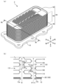
- FIG. 2(a) is a perspective view of the oil cooler 2.
- FIG. 2(a) is a perspective view of the oil cooler 2.
- FIG. The oil cooler 2 has a bottom flange 10 and a heat exchange section 20 .
- the bottom flange 10 is a member for attaching the oil cooler 2 to another structure such as an engine block.
- the bottom flange 10 is a metal plate.
- the bottom flange 10 has a plurality of through holes 11, oil outlets 12a and 12b, and cooling water outlets 13a and 13b.
- FIG. 3 is an exploded view of the oil cooler 2.
- the vertical direction is defined as a direction parallel to the thickness of the bottom flange 10 .
- a direction orthogonal to the vertical direction is defined as a front-rear direction
- a direction orthogonal to the vertical direction and the front-rear direction is defined as a left-right direction.
- the through-hole 11 is a hole for fixing with screws.
- the through hole 11 is a hole vertically penetrating the bottom flange 10 .
- the through hole 11 is provided in the outer peripheral edge of the bottom flange 10 so as not to overlap the mounting portion of the heat exchanging portion 20 .
- six through holes 11 are provided in the bottom flange 10 .
- the oil cooler 2 is attached to another structure by fitting a bolt (not shown) into the through hole 11 and fastening the bolt to another structure.
- the oil inflow/outlet ports 12a and 12b are openings through which engine oil flows.
- the rear opening of the bottom flange 10 is used as the oil inlet 12a, and the front opening is used as the oil outlet 12b.
- the cooling water inlet/outlets 13a and 13b are openings through which cooling water flows.
- the rear opening of the bottom flange 10 is used as the cooling water inlet 13a
- the front opening is used as the cooling water outlet 13b.
- the cooling water inlet 13a has a small diameter opening 14a and a large diameter opening 15a.
- the small-diameter opening 14a extends from the bottom surface toward the top surface of the bottom flange 10, and is connected to the large-diameter opening 15a.
- the large-diameter opening 15a extends upward from the small-diameter opening 14a to the upper surface of the bottom flange 10 .
- the large-diameter opening 15a is larger than the small-diameter opening 14a when viewed from above, and is provided such that the small-diameter opening 14a is disposed inside the large-diameter opening 15a.
- the cooling water outlet 13b has a small diameter opening 14b and a large diameter opening 15b.
- the structures of the small-diameter opening 14b and the large-diameter opening 15b are the same as the structures of the small-diameter opening 14a and the large-diameter opening 15a.
- the heat exchange unit 20 is a structure in which separate flow paths are formed for engine oil and cooling water, which are fluids, and heat is exchanged between the two fluids flowing through the respective flow paths.
- the heat exchange section 20 includes a bottom plate 30 , a laminated section 40 and a top plate 50 .
- the heat exchange section 20 is formed by stacking a laminated section 40 on the upper surface of the bottom plate 30 and further by stacking a top plate 50 on the upper surface of the laminated section 40 .
- the bottom plate 30 is a member arranged in the lowest layer of the heat exchange section 20 and attached to the bottom flange 10 .
- the bottom plate 30 is attached to the bottom surface of the bottom plate of the stack 40 .
- the bottom plate 30 is a mail plate 100 which will be described later.
- the laminated portion 40 is a structure in which plate members are vertically stacked to form separate flow paths for engine oil and cooling water.
- the laminated portion 40 is formed by stacking a plurality of plate assemblies 60 and joining them by brazing. In this embodiment, the laminated portion 40 is formed by stacking four plate assemblies 60 .
- Plate assembly 60 has male plate 100 , female plate 110 and fins 120 .
- 4 is an exploded view of the plate assembly 60.
- the plate assembly 60 is stacked with the male plate 100 facing upward and the female plate 110 facing downward, with the fins 120 arranged therebetween.
- a space is formed inside the plate assembly 60 by the male plate 100 and the female plate 110, and functions as a second flow path 132 through which the engine oil flows.
- FIG. 5 is a diagram in which the female plate 110 is arranged on the upper side and the male plate 100 is arranged on the lower side.
- a female plate 110 and a male plate 100 are arranged at the joint as shown in FIG.
- a space is formed by the female plate 110 and the male plate 100 at the joint of the two plate assemblies 60, and functions as a first flow path 131 through which cooling water flows.
- FIG.2(b) is the figure which simplified the cross section in the IIb position of Fig.2 (a).
- the bottom plate 30 is provided on the top surface of the bottom flange 10 .
- Female plates 110 and male plates 100 are alternately provided on the bottom plate 30 in the vertical direction.
- the space formed by providing the female plate 110 on the male plate 100 is the first flow path 131 .
- the space formed by the female plate 100 above the female plate 110 is the second channel 132 .
- the first flow paths 131 and the second flow paths 132 are alternately formed in the vertical direction. Since the first channel 131 and the second channel 132 are partitioned by the male plate 100 and the female plate 110, they are independent of each other.
- the cooling water flows in from the cooling water inlet 13 a and flows into the first flow path 131 . After flowing through the first flow path 131, the cooling water reaches the cooling water outlet 13b. The cooling water flows out to the radiator 5 from the cooling water outlet 13b.
- the engine oil flows in from the oil inlet 12 a and flows into the second flow path 132 . After flowing through the second flow path 132, the engine oil reaches the oil outlet 12b. The engine oil flows out to the oil pump 4 from the oil outlet 12b.
- the mail plate 100 is a member that exchanges heat between two fluids (engine oil and cooling water) flowing on the upper surface and the lower surface.
- the mail plate 100 is a metal plate member slightly smaller than the bottom flange 10 .
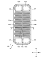
- FIG. 6 is a top view of the mail plate 100.
- the mail plate 100 is formed in a substantially rectangular shape with long sides extending in the front-rear direction and short sides extending in the left-right direction when viewed from above.
- the mail plate 100 includes an upper surface 100a having linear projections 104 formed thereon, a lower surface 100b having linear grooves 105 formed therein, edge portions 106 forming oil inlets and outlets 102a and 102b, and cooling water inlets and outlets 103a and 103b. and an edge 107 forming 103b.
- the oil inflow/outlet ports 102a and 102b are openings through which engine oil flows.
- the oil inlets 102a and 102b are provided at a pair of diagonal positions among the four corners of the mail plate 100. As shown in FIG.
- the openings of the oil inlets 102 a and 102 b are larger than the oil outlets 12 a and 12 b of the bottom flange 10 .
- the right rear opening of the mail plate 100 in FIG. 6 is used as an oil inlet 102a, and the left front opening of the mail plate 100 is used as an oil outlet 102b.
- Edges 106 of the oil inlets 102a and 102b protrude upward and have flat upper surfaces.
- the cooling water inlet/outlets 103a and 103b are openings through which the cooling water flows.
- the cooling water inlets/outlets 103a and 103b are provided at a pair of diagonal positions among the four corners of the mail plate 100 where the oil inlets/outlets 102a and 102b are not provided.
- the left rear opening of the mail plate 100 in FIG. 6 is used as the cooling water inlet 103a
- the right front opening is used as the cooling water outlet 103b.
- the size of the openings of the cooling water inflow/outlet ports 103a and 103b is the same as that of the large diameter openings 15a and 15b.
- the edge portion 107 protrudes downward and has a flat lower surface.
- the shape of the rim 107 matches the shape of the large diameter openings 15a, 15b.
- the length by which the edge portion 107 protrudes downward matches the depth of the large-diameter openings 15a and 15b.
- the protrusion 104 is a protrusion that disturbs the flow of fluid flowing on the upper surface 100a, protrudes upward from a flat portion of the upper surface 100a, and extends linearly in top view.
- a plurality of protrusions 104 are provided on the upper surface 100a.
- the upper surface 100a is partitioned into two regions 108a, 108b, and a plurality of protrusions 104 are provided in each of the regions 108a, 108b.
- the areas 108a and 108b are areas provided by partitioning the upper surface 100a.
- the regions 108a and 108b are rectangles extending in the front-rear direction.
- the regions 108a and 108b partition the upper surface 100a in a substantially symmetrical manner.
- the area provided on the left side of the upper surface 100a is the area 108a
- the area provided on the right side is the area 108b.
- the protrusions 104 provided in the regions 108a and 108b are referred to as protrusions 104a and 104b, respectively.
- the plurality of protrusions 104a provided in the region 108a are provided parallel to each other, and the plurality of protrusions 104b provided in the region 108b are also provided parallel to each other.
- the protrusion 104a extends in a direction crossing the protrusion 104b. Note that the plurality of protrusions 104a and 104b form a so-called herringbone pattern when viewed from above.
- the height of the protrusion 104 is about half the height of the space (first channel 131) formed when the female plate 110 is superimposed on the male plate 100.
- the protrusion 104 has a point-like protrusion junction 101 .
- the joining portion 101 is provided at a position where the projections 104 and 114 intersect when the female plate 110 is placed on the male plate 100 in top view.
- the groove 105 is a groove that disturbs the flow of fluid flowing through the lower surface 100b.
- FIG. 7 is a bottom view of the mail plate 100.
- FIG. A plurality of grooves 105 are provided so as to be recessed upward from a flat portion of the lower surface 100b, and extend linearly when viewed from the bottom. Since the grooves 105 and the protrusions 104 are formed by pressing, the grooves 105 have the same shape as the protrusions 104 when viewed in the vertical direction.
- the groove 105 overlaps the protrusion 104 in bottom view. That is, each groove 105 is paired with a protrusion 104 having the same shape and is provided on the lower surface 100b.
- the lower surface 100b is divided into two regions 108c and 108d, and a plurality of grooves 105 are provided in each of the regions 108c and 108d.
- the areas 108c and 108d are areas provided by partitioning the lower surface 100b.
- the regions 108c and 108d are rectangles extending in the front-rear direction.
- the regions 108c and 108d partition the lower surface 100b in a substantially symmetrical manner to the left and right.
- the area provided on the right side of the lower surface 100b is the area 108c
- the area provided on the left side is the area 108d.
- a region 108c is provided on the rear surface of the region 108a
- a region 108d is provided on the rear surface of the region 108b.
- the grooves 105 provided in the regions 108c and 108d are referred to as grooves 105a and 105b, respectively.
- Each groove 105a, 105b is paired with a projection 104a, 104b of the same shape.
- the plurality of grooves 105a provided in the region 108c are provided parallel to each other, and the plurality of grooves 105b provided in the region 108d are also provided parallel to each other.
- the groove 105a extends in a direction crossing the groove 105b. Note that the plurality of grooves 105a and 105b form a so-called herringbone pattern when viewed from below.
- the female plate 110 is a member that exchanges heat between two fluids (engine oil and cooling water) flowing on the upper surface and the lower surface.
- the female plate 110 is a metal plate having the same size as the female plate 100 .
- FIG. 8 is a top view of the female plate 110.
- the female plate 110 is formed in a substantially rectangular shape with long sides extending in the front-rear direction and short sides extending in the left-right direction when viewed from above.
- the female plate 110 includes an upper surface 110a having a linear groove 115 formed thereon, a lower surface 110b having a linear projection 114 formed thereon, an edge portion 116 forming oil inlets and outlets 112a and 112b, and a cooling water inlet port 113a. , 113b.
- the oil inflow/outlet ports 112a and 112b are openings through which engine oil flows.
- the oil inlets 112 a and 112 b are provided at a pair of diagonal positions among the four corners of the female plate 110 .
- the opening sizes of the oil inlets 112a, 112b are the same as those of the oil outlets 102a, 102b.
- the right rear opening of the female plate 110 in FIG. 8 is used as the oil inlet 112a
- the left front opening of the female plate 110 is used as the oil outlet 112b.
- the edge 116 of the oil inlet/outlet 112a, 112b protrudes downward and has a flat lower surface.
- the cooling water inlet/outlets 113a and 113b are openings through which cooling water flows.
- the cooling water inlets/outlets 113a and 113b are provided at a pair of diagonal positions among the four corners of the female plate 110 where the oil inlets/outlets 112a and 112b are not provided.
- the left rear opening of the female plate 110 in FIG. 8 is used as the cooling water inlet 113a
- the right front opening is used as the cooling water outlet 113b.
- the opening sizes of the cooling water inlets and outlets 113a and 113b are the same as those of the cooling water inlets and outlets 103a and 103b.
- the edge portion 117 protrudes upward and has a flat upper surface. The shape of edge 117 matches the shape of edge 107 .
- the oil outlets 102a, 102b and the oil outlets 112a, 112b will be described.
- the edge 106 forming the oil inlets 102a, 102b protrudes upward from the upper surface 100a.
- edge portions 116 forming the oil inlets 112a, 112b protrude downward from the upper surface 110a. Therefore, when the female plate 110 is overlaid on the male plate 100 as shown in FIG. 2(b), the edges 106 and 116 are connected.
- the upper and lower second flow paths 132 are connected through the oil inlets 102a, 102b and the oil outlets 112a, 112b. Therefore, since the upper and lower second flow paths 132 are connected in each of the second flow paths 132, all the second flow paths 132 are connected through the oil flow inlets 102a, 102b and the oil flow inlets 112a, 112b. ing.
- edge portions 107 forming cooling water inlets and outlets 103a and 103b protrude downward from the upper surface 100a.
- edge portions 117 forming cooling water inlets and outlets 113a and 113b protrude upward from the upper surface 110a. Therefore, when the male plate 100 is overlaid on the female plate 110 as shown in FIG. 2(b), the edges 107 and 117 are connected.
- the upper and lower first flow paths 131 are connected through the cooling water inlet/outlet ports 103a, 103b and the cooling water inlet/outlet ports 113a, 113b. Therefore, since the upper and lower first flow paths 131 are connected in each of the first flow paths 131, all the first flow paths 131 are connected through the cooling water inlets and outlets 103a, 103b and the cooling water inlets and outlets 113a, 113b. ing.
- the cooling water inlets and outlets 103a, 103b and the cooling water inlets and outlets 113a, 113b are open to the first flow path 131, but the oil inlets and outlets 102a, 102b and the oil inlets and outlets 112a, 112b are open to the first flow path. Closed to 131.
- the oil inlets 102a, 102b and the oil outlets 112a, 112b are open to the second flow path 132, but the cooling water inlets 103a, 103b and the cooling water inlets 113a, 113b are open to the second flow path 132. closed to Therefore, the first channel 131 is independent of the second channel 132 .
- the groove 115 is a groove that disturbs the flow of fluid flowing on the upper surface 110a.
- a plurality of grooves 115 are provided so as to be recessed downward from a flat portion of the upper surface 110a, and extend linearly when viewed from above.
- the upper surface 110a is partitioned into two regions 118a and 118b, and a plurality of grooves 115 are provided in each of the regions 118a and 118b.
- the areas 118a and 118b are areas provided by partitioning the upper surface 110a.
- the regions 118a and 118b are rectangles extending in the front-rear direction.
- the regions 118a and 118b partition the upper surface 110a substantially symmetrically in the left-right direction.
- the area provided on the left side of the upper surface 110a is the area 118a
- the area provided on the right side is the area 118b.
- the grooves 115 provided in the regions 118a and 118b are referred to as grooves 115a and 115b, respectively.
- the plurality of grooves 115a provided in the region 118a are provided parallel to each other, and the plurality of grooves 115b provided in the region 118b are also provided parallel to each other.
- the groove 115a extends in a direction crossing the groove 115b. Note that the plurality of grooves 115 form a so-called herringbone pattern when viewed from above.
- the protrusion 114 is a protrusion that disturbs the flow of fluid flowing on the lower surface 110b, protrudes downward from a flat portion of the lower surface 110b, and extends linearly in a bottom view.
- FIG. 9 is a bottom view of the female plate 110.
- FIG. A plurality of protrusions 114 are provided on the lower surface 110b. Since the protrusion 114 and the groove 115 are formed by press working, the protrusion 114 has the same shape as the groove 115 when viewed in the vertical direction. The protrusion 114 overlaps the groove 115 in bottom view. That is, each protrusion 114 is paired with a groove 115 having the same shape and is provided on the lower surface 110b.
- the lower surface 110b is divided into two regions 118c and 118d, and a plurality of protrusions 114 are provided in each of the regions 118c and 118d.
- the areas 118c and 118d are areas provided by partitioning the lower surface 110b.
- the regions 118c and 118d are rectangles extending in the front-rear direction.
- the regions 118c and 118d partition the lower surface 110b in a substantially symmetrical manner to the left and right.
- the area provided on the right side of the lower surface 110b is the area 118c
- the area provided on the left side is the area 118d.
- a region 118c is provided on the rear surface of the region 118a
- a region 118d is provided on the rear surface of the region 118b.
- the protrusions 114 provided in the respective regions 118c and 118d are referred to as protrusions 114a and 114b, respectively.
- Each protrusion 114a, 114b is paired with a groove 115a, 115b of the same shape. That is, the plurality of protrusions 114a provided in the region 118c are provided parallel to each other, and the plurality of protrusions 114b provided in the region 118d are also provided parallel to each other.
- the protrusion 114a extends in a direction crossing the protrusion 114b.
- the plurality of protrusions 114 form a so-called herringbone pattern when viewed from the bottom. Further, when the male plate 100 and the female plate 110 are overlapped, the projection 114 is provided in a direction intersecting with the projection 104 in a bottom view.
- the height of the protrusion 114 is about half the height of the space (first channel 131) formed when the female plate 110 is placed on the male plate 100.
- Protrusion 114 joins protrusion 114 to protrusion 104 by coming into contact with joint 101 , forming joint 111 having a point-like recess recessed upward from the lower surface of protrusion 114 .
- the dot-like protrusion of the joint 101 and the dot-like depression of the joint 111 are paired.
- the joining portion 111 is provided at a position where the projections 104 and 114 intersect when the female plate 110 is placed on the male plate 100 in a bottom view.
- the fins 120 are members that complicate the flow of the passing fluid and exchange heat with the fluid.
- the fin 120 is a metal member having a large number of rectangular holes formed by combining a thin plate extending in the front, rear, up and down direction and a thin plate extending in the left, right, up and down direction in a rectangular shape, and has a flat plate-like outer shape.
- the thickness of the fins 120 is substantially the same as the height of the space (second flow path 132) formed by the male plate 100 and the female plate 110, as shown in FIG.
- the upper surface of the fin 120 contacts the lower surface 100b.
- the lower surface of fin 120 contacts upper surface 110a.
- the top plate 50 is a member arranged as the uppermost member of the heat exchange section 20 .
- the top plate 50 is a kind of female plate 110, and has a shape obtained by removing the oil inlets 112a and 112b and the cooling water inlets 113a and 113b from the female plate 110. As shown in FIG. Therefore, in the top plate 50, the same components as those of the female plate 110 are denoted by the same reference numerals.
- the top plate 50 has an upper surface 110a in which linear grooves 115 are formed and a lower surface 110b in which linear protrusions 114 are formed.
- the top plate 50 is joined to the upper surface of the mail plate 100, which is the uppermost layer member of the laminate section 40, by brazing. As a result, the oil inlets 102a and 102b of the mail plate 100 joined to the lower surface of the top plate 50 are closed.
- ⁇ Oil cooler operation> The operation of the oil cooler 2 will be explained. Inside the oil cooler 2 , cooling water flows through the first flow path 131 . Engine oil flows through the second flow path 132 . The first channel 131 and the second channel 132 are vertically adjacent to each other with the mail plate 100 or the female plate 110 interposed therebetween. Therefore, cooling water and engine oil exchange heat through the male plate 100 or the female plate 110 . That is, the high temperature engine oil is cooled by the low temperature cooling water. Conversely, the cold coolant is heated by the hot engine oil.
- cooling water is supplied from the cooling water flow path 8 to the cooling water inlet 13a.
- the cooling water flows from the cooling water inlet 13a into the first channel 131 in the bottom layer. Cooling water flows into all the first flow paths 131 through the cooling water inlets 103a and 113a.
- the cooling water flows from the cooling water inlets 103a and 113a to spread over the entire first flow path 131.
- the cooling water then flows into the cooling water outlets 103b and 113b.
- a part of the cooling water that has flowed in comes into contact with the protrusions 104 and 114 when flowing through the first flow path 131 . Since the protrusions 104 and 114 protrude vertically, cooling water in contact with the protrusions 104 and 114 generates a vertical flow. Moreover, since the protrusions 104 and 114 are provided so as to intersect the flow direction of the cooling water, the cooling water in contact with the protrusions 104 and 114 generates lateral flows according to the crossing angle. Furthermore, when the projections 104 and 114 come into contact at the positions of the joints 101 and 111, the projections 104 and 114 at those positions become columnar. Therefore, part of the cooling water generates a flow avoiding the columnar protrusions 104 and 114 . Thus, the cooling water generates complicated flows when flowing through the first flow path 131 .
- the cooling water exchanges heat with the engine oil via the male plate 100 and the female plate 110 when flowing through the first flow path 131 .
- the surface area of the mail plate 100 is increased by the provision of the projections 104 .
- the surface area of the female plate 110 is increased by the amount of the projections 114 provided.
- the greater the contact area between the cooling water and the member that performs heat exchange the higher the efficiency of heat exchange by the cooling water. Therefore, the efficiency of heat exchange by the cooling water flowing through the first flow path 131 is high.
- the cooling water flows through the respective first flow paths 131 and flows into the cooling water outlets 103b and 113b. Cooling water flows into cooling water outlet 13b through cooling water outlets 103b and 113b. The cooling water flows into the radiator 5 through the cooling water flow path 8 from the cooling water outlet 13b.
- engine oil As indicated by arrows in FIG. 2(b), the engine oil is supplied from the oil flow path 7 to the oil inlet 12a.
- the engine oil flows from the oil inlet 12a into the lowermost second flow path 132 .
- Engine oil flows into all of the second flow paths 132 through the oil inlets 102a, 112a.
- the engine oil spreads and flows from the oil inlets 102a and 112a to the entire second flow path 132 as indicated by the arrows in FIG.
- the engine oil then flows into the oil outlets 102b, 112b.
- the engine oil that has flowed in comes into contact with the fins 120 when flowing through the second flow path 132 . Also, the engine oil flows through the holes formed in the fins 120 and the grooves 105 and 115 . The engine oil flowing through the second flow path 132 contacts the fins 120 and flows through the grooves 105 and 115 to generate lateral and vertical flows.
- the engine oil flows through the second flow path 132, it exchanges heat with the cooling water via the male plate 100, the female plate 110, and the fins 120. Since the fins 120 are in contact with the lower surface 100b and the upper surface 110a, heat is transferred between the fins 120 and the male plate 100 and between the fins 120 and the female plate 110. FIG. That is, the fins 120 increase the area over which the engine oil exchanges heat. Also, the surface area of the mail plate 100 is increased by the groove 105 provided. Similarly, the surface area of female plate 110 is increased by the provision of groove 115 . Therefore, the efficiency of heat exchange by the engine oil flowing through the second flow path 132 is high.
- the engine oil passes through the fins 120 when flowing through the second flow path 132 .
- the fins 120 make it difficult for engine oil to flow in the second flow path 132 .
- the pressure loss in the second flow path 132 increases.
- the upper and lower surfaces of fin 120 are in contact with grooves 105 and 115 . Since the size of the grooves 105 and 115 is larger than the size of the flow paths inside the fins 120 , part of the engine oil passing through the fins 120 flows from inside the fins 120 to the grooves 105 and 115 .
- the engine oil flows through each of the second flow paths 132 and flows into the oil outlets 102b and 112b.
- Engine oil flows into oil outlet 12b through oil outlets 102b and 112b.
- the engine oil flows into the oil pump 4 through the oil flow path 7 from the oil outlet 12b.
- the oil cooler 2 has an upper surface 100a or a lower surface 110b with which cooling water contacts, and a plate (mail plate 100 or female plate 110) formed with a plurality of linearly extending projections 104, 114 on the upper surface 100a. ).
- the contact area between the cooling water and the plate is increased by forming the protrusions 104 and 114 that contact the cooling water on the plate. As the contact area between the cooling water and the plate in contact with the cooling water during heat exchange increases, the efficiency of heat exchange by the cooling water increases, so the efficiency of heat exchange by the oil cooler 2 increases.
- the contact of the cooling water with the protrusions 104 changes the flow of the cooling water along the protrusions 104 . Therefore, the flow of cooling water becomes complicated. As the cooling water generates a more complicated flow, the efficiency of heat exchange by the cooling water becomes higher, so the efficiency of heat exchange by the oil cooler 2 becomes higher.
- the plurality of projections 104 and 114 of the oil cooler 2 according to the present embodiment each extend so as to intersect the direction in which the cooling water flows.
- the plurality of projections 104 and 114 extend so as to intersect the direction of flow of the cooling water, so that when the cooling water comes into contact with the projections 104 and 114, the direction of flow of the cooling water intersects with the projections 104 and 114.
- a flow of cooling water is generated according to the angle at which the Therefore, since the cooling water generates a complicated flow, the efficiency of heat exchange is increased.
- the upper surface 100a or the lower surface 110b of the oil cooler 2 is divided into regions 108a and 108b, or regions 118c and 118d, which extend in the direction in which the cooling water flows.
- the projection 104a in the region 108a and the projection 104b in the region 108b, or the projection 114a in the region 118c and the projection 114b in the region 118d extend in directions crossing each other.
- the upper surface 100a or the lower surface 110b is divided into a region 108a and a region 108b, or a region 118c and a region 118d, respectively extending in the direction in which the cooling water flows.
- the projections 114a in the region 118c and the projections 114d in the region 118d extend in directions intersecting each other, the direction of the flow of the cooling water flowing in the region 108a changes from that of the flow of the cooling water flowing in the region 108b. different direction.
- the direction of flow of cooling water flowing through the region 118c is different from the direction of flow of cooling water flowing through the region 118d. Therefore, since the cooling water generates a complicated flow, the efficiency of heat exchange is increased.
- the plate of the oil cooler 2 according to the present embodiment further includes a lower surface 100b on the opposite side of the upper surface 100a or an upper surface 110a on the opposite side of the lower surface 110b, which is in contact with the engine oil that exchanges heat with the cooling water.
- a plurality of linearly extending grooves 105 and 115 are formed in the lower surface 100b or the upper surface 110a.
- the plate has a lower surface 100b opposite to the upper surface 100a or an upper surface 110a opposite to the lower surface 110b in contact with the engine oil for heat exchange with the cooling water, and the lower surface 100b or the upper surface 110a has a linear
- the lower surface 100b or the upper surface 110a has a corrugated shape. Therefore, the contact area between the engine oil and the plate increases. Since the efficiency of heat exchange by the engine oil increases as the contact area with the members that come into contact with the engine oil during heat exchange increases, the efficiency of heat exchange by the oil cooler 2 increases.
- the engine oil flows along the grooves 105 and 115 because the lower surface 100b or the upper surface 110a has a wavy shape. As a result, the engine oil generates a complex flow, which increases the efficiency of heat exchange.
- the cooling water and engine oil exchange heat through the plate. Not only the efficiency of heat exchange between the upper surface 100a or the lower surface 110b and the coolant, but also the efficiency of heat exchange between the lower surface 100b or the upper surface 110a and the engine oil increases, so the efficiency of the heat exchange of the entire oil cooler 2 is high. Become.
- the plurality of grooves 105 and 115 of the oil cooler 2 according to the present embodiment each extend so as to intersect the direction in which the engine oil flows.
- the plurality of grooves 105 and 115 extend so as to intersect the flow direction of the engine oil, when the engine oil flows along the grooves 105 and 115, the flow direction of the engine oil and the grooves 105 and 115 intersect.
- a flow of engine oil is generated according to the angle of rotation. Therefore, the engine oil generates a complicated flow, which increases the efficiency of heat exchange.
- the lower surface 100b or the upper surface 110a of the oil cooler 2 is divided into a region 108c and a region 108d or a region 118a and a region 118b extending in the direction in which the engine oil flows.
- the groove 105a in the region 108c and the groove 105b in the region 108d, or the groove 115a in the region 118a and the groove 115b in the region 118b extend in directions crossing each other.
- the lower surface 100b or the upper surface 110a is divided into a region 108c and a region 108d, or a region 118a and a region 118b, respectively extending in the direction in which the engine oil flows.
- the grooves 115a in the region 118a and the grooves 115b in the region 118b extend in the directions intersecting each other, the direction of the engine oil flowing in the region 108c is changed from the direction of the engine oil flowing in the region 108d. different from Alternatively, the direction of the engine oil flowing in the region 118a is different from the direction of the engine oil flowing in the region 118b. Therefore, the engine oil generates a complicated flow, which increases the efficiency of heat exchange.
- the oil cooler 2 contacts at least one of the plurality of projections 104 and the lower surface 100b, or contacts at least one of the plurality of projections 114 and the upper surface 110a. Further provided are fins 120 for diffusing the flow of cooling water or engine oil in contact with one or the other.
- the fins 120 are in contact with the plate because the fins 120 contact either one of the protrusions 104 or the lower surface 100b, or the protrusions 114 or the upper surface 110a. Therefore, the number of members that exchange heat with cooling water or engine oil is increased. As a result, the efficiency of heat exchange in the entire oil cooler 2 increases.
- the fins 120 increase the efficiency of heat exchange as described above.
- the fins 120 increase the resistance in the cooling water or engine oil flow path, the pressure loss in the flow path increases.
- the fins 120 come into contact with either the protrusions 104 or the bottom surface 100b, the fins 120 are in contact with the grooves formed between the multiple protrusions 104 or the grooves 105 formed on the bottom surface 100b. Contact.
- the fins 120 contact either the protrusions 114 or the upper surface 110a, the fins 120 contact the grooves formed between the plurality of protrusions 114 or the grooves 115 formed in the upper surface 110a at the contact portion. . Since these grooves function as channels for cooling water or engine oil, the pressure loss in the channels is reduced. That is, the effect of increasing the efficiency of heat exchange by the fins 120 while suppressing an increase in pressure loss in the flow path is obtained.
- the plurality of projections 104, 114 of the oil cooler 2 overlap the plurality of grooves 105, 115 when viewed from the direction orthogonal to the upper surface 100a or the lower surface 110b.
- the plurality of protrusions 104 and 114 overlap the plurality of grooves 105 and 115 when viewed from the orthogonal direction of the upper surface 100a or the lower surface 110b, so that the protrusion 104 and the groove 105 or the protrusion 114 and the groove 115 are the same on the front and back surfaces of the plate. in position.
- the thickness of the plate in order to provide the grooves 105 and 115 on the lower surface 100b or the upper surface 110a, the thickness of the plate must be greater than the depth of the grooves 105 and 115.
- the groove 105 from the lower surface 100b to the protrusion of the protrusion 104 or the protrusion of the protrusion 114 Since the grooves 115 can be provided from the upper surface 110a by using the upper surface 110a, the plate can be made thinner. As a result, the oil cooler 2 becomes thinner.
- the oil cooler 2 further includes a plate having a lower surface 110b or an upper surface 100a with which cooling water contacts, and a plurality of linearly extending projections 114, 104 formed on the lower surface 110b or the upper surface 100a. , the upper surface 100a faces the lower surface 110b.
- the oil cooler 2 includes a plate having a lower surface 110b or an upper surface 100a with which cooling water contacts, and a plurality of linearly extending projections 114, 104 formed on the lower surface 110b or the upper surface 100a. Since the upper surface 100a and the lower surface 110b face each other, the cooling water flows between the upper surface 100a and the lower surface 110b. Therefore, the cooling water generates a more complex flow because it contacts not only projections 104 but also projections 114 . As a result, the efficiency of heat exchange increases.
- At least one of the multiple projections 104 of the oil cooler 2 according to this embodiment is in contact with the multiple projections 114 .
- At least one of the plurality of protrusions 104 is in contact with the plurality of protrusions 114, so that the contact portion of the two protrusions forms a pillar or wall between the upper surface 100a and the lower surface 110b. Therefore, the cooling water generates a more complicated flow as it flows avoiding the columns or walls. As a result, the efficiency of heat exchange increases.
- the oil cooler 2 since the pillars or walls are formed between the plates, the oil cooler 2 has high strength against the force acting in the direction in which the plates face each other.
- the plurality of projections 104 of the oil cooler 2 each extend in a direction intersecting with the plurality of projections 114 .
- the direction of the wave shape formed on the upper surface 100a differs from the direction of the wave shape formed on the lower surface 110b. Therefore, as the cooling water flows between the upper surface 100a and the lower surface 110b, the cooling water generates complex flows. As a result, the efficiency of heat exchange increases.
- the configuration of the heat exchange system 1 may be different.
- the oil pump 4 and water pump 6 may be arranged at different positions.
- the engine 3 may be replaced with a transmission or a motor. In this case, engine oil is replaced with transmission oil or motor oil.
- the fluid that exchanges heat with water may be gas.
- the oil cooler 2 functions as an EGR cooler for an EGR (Exhaust Gas Recirculation) system that recirculates the exhaust gas from the engine 3 and mixes it with the intake gas of the engine 3 .
- the EGR cooler takes in a part of the exhaust gas discharged from the engine 3 and exchanges heat between the exhaust gas and water to cool the exhaust gas.
- the exhaust gas cooled by the EGR cooler is mixed with the intake gas of the engine 3 .
- the heat exchange system 1 has the oil pump 4 removed and the oil flow path 7 becomes the gas flow path.
- the direction of flow of engine oil and cooling water may be different. That is, in this embodiment, the engine oil flows from the oil flow path 7 through the oil inlet 12a, the oil inlet 112a, the second flow path 132, the oil outlet 112b, and the oil outlet 12b in this order. 7 to the oil outlet 12b, the oil outlet 112b, the second flow path 132, the oil inlet 112a, and the oil inlet 12a in this order.
- the cooling water may flow from the cooling water flow path 8 through the cooling water outlet 13b, the cooling water outlet 103b, the first flow path 131, the cooling water inlet 103a, and the cooling water inlet 13a in this order.
- Modification 5 The plurality of protrusions 104 and 114 do not have to extend so as to intersect the direction in which the cooling water flows. In this case, at least one of the multiple projections 104 and 114 extends parallel to the direction in which the cooling water flows.
- the upper surface 100a or the lower surface 110b may not be divided into the regions 108a and 108b or the regions 118c and 118d extending in the direction in which the cooling water flows.
- the protrusion 104a and the protrusion 104b in the region 108b, or the protrusion 114a in the region 118c and the protrusion 114b in the region 118d do not have to extend in the directions crossing each other.
- the top surface 100a or the bottom surface 110b is not divided into two regions.
- the plurality of protrusions 104 or the protrusions 114 may extend parallel to each other, or may extend in directions crossing each other.
- the plate may not be formed with a plurality of grooves 105 or grooves 115 linearly extending in the lower surface 100b or the upper surface 110a.
- the lower surface 100b or the upper surface 110a may be flat.
- the lower surface 100b or the upper surface 110a may be embossed or provided with protrusions or bosses.
- Each of the plurality of grooves 105, 115 does not have to extend so as to intersect the direction in which the engine oil flows. In this case, at least one of the plurality of grooves 105, 115 extends parallel to the direction in which the engine oil flows.
- the lower surface 100b or the upper surface 110a does not have to be divided into the regions 108c and 108d, or the regions 118a and 118b, which extend in the direction in which the engine oil flows.
- the groove 105a and the groove 105b in the region 108d, or the groove 115a in the region 118a and the groove 115b in the region 118b do not have to extend in directions crossing each other.
- the lower surface 100b or the upper surface 110a are not partitioned into two regions.
- the plurality of grooves 105 or the plurality of grooves 115 may extend parallel to each other, or may extend in directions crossing each other.
- Oil cooler 2 may not have fins 120 that contact lower surface 100b or upper surface 110a. In this case, the fins 120 are not provided in the second flow paths 132 .
- the oil cooler 2 may include fins 120 that contact the protrusions 104,114.
- the height of the protrusions 104 and 114 and the height of the fin 120 are changed, and the fin 120 is provided in the first flow path 131 so as to contact the protrusions 104 and 114 .
- the plurality of protrusions 104, 114 may not overlap the plurality of grooves 105, 115 when viewed from the orthogonal direction of the upper surface 100a or the lower surface 110b. In this case, the plurality of protrusions 104, 114 are offset from the plurality of grooves 105, 115 when viewed from the direction orthogonal to the upper surface 100a or the lower surface 110b, so the plate becomes thicker by the depth of the grooves 105, 115. .
- the oil cooler 2 may have only one of the male plate 100 and the female plate 110 .
- the laminated portion 40 may be formed by alternately stacking the male plate 100 and a plate other than the female plate 110 in the vertical direction, or by alternately stacking the female plate 110 and the plate other than the male plate 100 in the vertical direction. It can be layered.
- the plurality of protrusions 104,114 may not contact the plurality of protrusions 114,104. In this case, for example, the height of the plurality of protrusions 104 and 114 is less than half the height of the first channel 131 and the second channel 132 .
- the plurality of protrusions 104, 114 may not extend in the direction intersecting the plurality of protrusions 114, 104, respectively. In this case, at least one of the plurality of protrusions 104, 114 extends parallel to the plurality of protrusions 114, 104.
- the plurality of protrusions 104, 114 and the plurality of grooves 105, 115 may not be linear.
- the lines formed by the plurality of projections 104, 114 and the plurality of grooves 105, 115 include straight lines, curved lines and polygonal lines. Therefore, the plurality of protrusions 104, 114 and the plurality of grooves 105, 115 may be curved or polygonal.
- the polygonal line shape is, for example, a V shape, an inverted V shape, an X shape, etc., and also includes a shape combining these shapes.
- the plurality of protrusions 104, 114 and grooves 105, 115 may be configured in a plurality of line types.
- the plurality of protrusions 104, 114 and the plurality of grooves 105, 115 are configured in a single plate with straight and curved shapes.
- the top plate 50 may be provided with oil inlets 52a, 52b and cooling water outlets 53a, 53b.
- the oil inlets 52a, 52b and the cooling water inlets 53a, 53b are tubular members attached to openings provided at the four corners of the top plate 50.
- the oil inlet 52a is attached to the rear right side in top view.
- the member attached to the left front is the oil outlet 52b
- the member attached to the left rear is the cooling water inlet 53a
- the member attached to the right front is the cooling water outlet 53b.
- the oil outlets 52a and 52b are connected to the oil flow path 7 to form a flow path for engine oil.
- the cooling water inlets and outlets 53a and 53b are connected to the cooling water flow path 8 to form a cooling water flow path.
- the plurality of projections 104, 114 and grooves 105, 115 are provided in rectangular regions 108a, 108b, 108c, 108d, 118a, 118b, 118c, 118d, but the other top surfaces 100a, 118d are provided. 110a and lower surfaces 100b, 110b.
- the sizes of the oil inlets 102a and 102b and the cooling water inlets 103a and 103b are reduced only in the horizontal direction, and are arranged at the ends of the mail plate 100 in the horizontal direction.
- the upper surface 100a and the lower surface 100b are formed with flat portions between the oil inlet 102a and the cooling water inlet 103a and between the oil outlet 102b and the cooling water outlet 103b. Protrusions 104 and grooves 105 are provided on these planar portions.
- the angle formed by the projections 104a and 104b intersecting with a straight line extending in the front-rear direction as the center line when viewed from the top is determined by the intersection of the projections 114a and 114b with the straight line extending in the front-rear direction as the center line when viewed from the top. is the same as the magnitude of the angle formed by
- the protrusions 104a and 104b are provided so that the angle formed by intersecting the protrusions 104a and 104b with a straight line extending in the front-rear direction as the center line when viewed from above is 30 degrees, and the straight line extending in the front-rear direction when viewed from the top is the center line.
- 114a and 114b are provided so that the angle formed by the intersections is 120 degrees.
- Oil cooler heat exchanger
- Mail plate first plate
- first plate 100a... Upper surface (first surface) 100b... Lower surface (opposite surface)
- Protrusion first protrusion
- second protrusion 105
- Groove 108a Area (first area) 108b... area (second area) 108c... area (third area) 108d... area (fourth area)
- Female plate second plate
- 110a Lower surface (second surface)
- Protrusion (second protrusion) 120 ... Fin (diffusion member)
Landscapes
- Engineering & Computer Science (AREA)
- Physics & Mathematics (AREA)
- Thermal Sciences (AREA)
- Mechanical Engineering (AREA)
- General Engineering & Computer Science (AREA)
- Heat-Exchange Devices With Radiators And Conduit Assemblies (AREA)
- Lubrication Of Internal Combustion Engines (AREA)
Priority Applications (5)
| Application Number | Priority Date | Filing Date | Title |
|---|---|---|---|
| US18/713,943 US20250027724A1 (en) | 2021-11-29 | 2021-11-29 | Heat exchanger |
| CN202180104118.7A CN118541580A (zh) | 2021-11-29 | 2021-11-29 | 热交换器 |
| EP21965715.2A EP4443092A4 (en) | 2021-11-29 | 2021-11-29 | HEAT EXCHANGER |
| JP2023563494A JPWO2023095349A1 (https=) | 2021-11-29 | 2021-11-29 | |
| PCT/JP2021/043670 WO2023095349A1 (ja) | 2021-11-29 | 2021-11-29 | 熱交換器 |
Applications Claiming Priority (1)
| Application Number | Priority Date | Filing Date | Title |
|---|---|---|---|
| PCT/JP2021/043670 WO2023095349A1 (ja) | 2021-11-29 | 2021-11-29 | 熱交換器 |
Publications (1)
| Publication Number | Publication Date |
|---|---|
| WO2023095349A1 true WO2023095349A1 (ja) | 2023-06-01 |
Family
ID=86539266
Family Applications (1)
| Application Number | Title | Priority Date | Filing Date |
|---|---|---|---|
| PCT/JP2021/043670 Ceased WO2023095349A1 (ja) | 2021-11-29 | 2021-11-29 | 熱交換器 |
Country Status (5)
| Country | Link |
|---|---|
| US (1) | US20250027724A1 (https=) |
| EP (1) | EP4443092A4 (https=) |
| JP (1) | JPWO2023095349A1 (https=) |
| CN (1) | CN118541580A (https=) |
| WO (1) | WO2023095349A1 (https=) |
Families Citing this family (1)
| Publication number | Priority date | Publication date | Assignee | Title |
|---|---|---|---|---|
| USD1105015S1 (en) * | 2021-10-20 | 2025-12-09 | Nexark, Inc. | SSD heat sink |
Citations (6)
| Publication number | Priority date | Publication date | Assignee | Title |
|---|---|---|---|---|
| JPS4839721Y1 (https=) * | 1968-08-28 | 1973-11-21 | ||
| JPH11287580A (ja) * | 1997-07-17 | 1999-10-19 | Denso Corp | 熱交換器 |
| JP2010054187A (ja) * | 2008-08-01 | 2010-03-11 | Toshihiro Yamamoto | プレート式熱交換器 |
| JP4527557B2 (ja) | 2005-01-26 | 2010-08-18 | 株式会社ティラド | 熱交換器 |
| JP2011002122A (ja) * | 2009-06-17 | 2011-01-06 | Mitsubishi Electric Corp | プレート式熱交換器 |
| JP2019078441A (ja) * | 2017-10-24 | 2019-05-23 | 株式会社日阪製作所 | プレート式熱交換器 |
Family Cites Families (6)
| Publication number | Priority date | Publication date | Assignee | Title |
|---|---|---|---|---|
| JP2001355978A (ja) * | 2000-06-12 | 2001-12-26 | Toyo Radiator Co Ltd | 気体冷却用積層型熱交換器 |
| ITVR20020051U1 (it) * | 2002-08-26 | 2004-02-27 | Benetton Bruno Ora Onda Spa | Scambiatore di calore a piastre. |
| JP5253116B2 (ja) * | 2008-12-01 | 2013-07-31 | 株式会社日阪製作所 | プレート式熱交換器 |
| EP3472547A1 (en) * | 2016-06-20 | 2019-04-24 | SWEP International AB | Heat exchanger |
| SE1651224A1 (en) * | 2016-09-12 | 2018-03-13 | Swep Int Ab | Heat exchanger having through hole for fastening of hydro block |
| SE545690C2 (en) * | 2020-01-30 | 2023-12-05 | Swep Int Ab | A brazed plate heat exchanger and use thereof |
-
2021
- 2021-11-29 JP JP2023563494A patent/JPWO2023095349A1/ja active Pending
- 2021-11-29 US US18/713,943 patent/US20250027724A1/en active Pending
- 2021-11-29 CN CN202180104118.7A patent/CN118541580A/zh active Pending
- 2021-11-29 EP EP21965715.2A patent/EP4443092A4/en active Pending
- 2021-11-29 WO PCT/JP2021/043670 patent/WO2023095349A1/ja not_active Ceased
Patent Citations (6)
| Publication number | Priority date | Publication date | Assignee | Title |
|---|---|---|---|---|
| JPS4839721Y1 (https=) * | 1968-08-28 | 1973-11-21 | ||
| JPH11287580A (ja) * | 1997-07-17 | 1999-10-19 | Denso Corp | 熱交換器 |
| JP4527557B2 (ja) | 2005-01-26 | 2010-08-18 | 株式会社ティラド | 熱交換器 |
| JP2010054187A (ja) * | 2008-08-01 | 2010-03-11 | Toshihiro Yamamoto | プレート式熱交換器 |
| JP2011002122A (ja) * | 2009-06-17 | 2011-01-06 | Mitsubishi Electric Corp | プレート式熱交換器 |
| JP2019078441A (ja) * | 2017-10-24 | 2019-05-23 | 株式会社日阪製作所 | プレート式熱交換器 |
Non-Patent Citations (1)
| Title |
|---|
| See also references of EP4443092A4 |
Also Published As
| Publication number | Publication date |
|---|---|
| EP4443092A1 (en) | 2024-10-09 |
| US20250027724A1 (en) | 2025-01-23 |
| EP4443092A4 (en) | 2025-09-03 |
| JPWO2023095349A1 (https=) | 2023-06-01 |
| CN118541580A (zh) | 2024-08-23 |
Similar Documents
| Publication | Publication Date | Title |
|---|---|---|
| TWI768877B (zh) | 均溫板結構 | |
| CN111316057B (zh) | 多流体热交换器 | |
| CN102939509B (zh) | 板式热交换器、油冷却系统以及用于冷却油的方法 | |
| US20240151475A1 (en) | Heat Exchanger | |
| JP5531570B2 (ja) | 沸騰冷却式熱交換器 | |
| WO2023095349A1 (ja) | 熱交換器 | |
| WO2022083674A1 (zh) | 一种换热器、换热组件及一种热管理系统 | |
| JPWO2018216165A1 (ja) | プレート式熱交換器 | |
| CN111765786A (zh) | 换热器与换热器组件 | |
| JP6492148B1 (ja) | プレート式熱交換器 | |
| WO2025126862A1 (ja) | 熱交換器 | |
| JP2002267391A (ja) | 熱交換器 | |
| JP2000337784A (ja) | 三液用プレート式熱交換器 | |
| JP7765995B2 (ja) | 熱交換器 | |
| JP7741571B2 (ja) | 熱交換器及びその製造方法 | |
| JP2009192140A (ja) | プレート式熱交換器 | |
| JP2008106969A (ja) | プレート型熱交換器 | |
| JP2005121319A (ja) | 熱交換器 | |
| JP7725404B2 (ja) | 熱交換器 | |
| JPWO2018216166A1 (ja) | プレート式熱交換器 | |
| JP3041506B2 (ja) | 熱交換器 | |
| JP7852979B2 (ja) | 熱交換器 | |
| JP3769869B2 (ja) | プレート式熱交換器 | |
| JP7721402B2 (ja) | 熱交換器 | |
| JP7647819B1 (ja) | 熱交換器 |
Legal Events
| Date | Code | Title | Description |
|---|---|---|---|
| 121 | Ep: the epo has been informed by wipo that ep was designated in this application |
Ref document number: 21965715 Country of ref document: EP Kind code of ref document: A1 |
|
| WWE | Wipo information: entry into national phase |
Ref document number: 202180104118.7 Country of ref document: CN |
|
| ENP | Entry into the national phase |
Ref document number: 2023563494 Country of ref document: JP Kind code of ref document: A |
|
| WWE | Wipo information: entry into national phase |
Ref document number: 18713943 Country of ref document: US |
|
| NENP | Non-entry into the national phase |
Ref country code: DE |
|
| ENP | Entry into the national phase |
Ref document number: 2021965715 Country of ref document: EP Effective date: 20240701 |