WO2023090331A1 - 灯具システムおよびランプの制御方法 - Google Patents
灯具システムおよびランプの制御方法 Download PDFInfo
- Publication number
- WO2023090331A1 WO2023090331A1 PCT/JP2022/042450 JP2022042450W WO2023090331A1 WO 2023090331 A1 WO2023090331 A1 WO 2023090331A1 JP 2022042450 W JP2022042450 W JP 2022042450W WO 2023090331 A1 WO2023090331 A1 WO 2023090331A1
- Authority
- WO
- WIPO (PCT)
- Prior art keywords
- light
- pitch angle
- pixel group
- vehicle body
- controller
- Prior art date
- Legal status (The legal status is an assumption and is not a legal conclusion. Google has not performed a legal analysis and makes no representation as to the accuracy of the status listed.)
- Ceased
Links
Images





Classifications
-
- B—PERFORMING OPERATIONS; TRANSPORTING
- B60—VEHICLES IN GENERAL
- B60Q—ARRANGEMENT OF SIGNALLING OR LIGHTING DEVICES, THE MOUNTING OR SUPPORTING THEREOF OR CIRCUITS THEREFOR, FOR VEHICLES IN GENERAL
- B60Q1/00—Arrangement of optical signalling or lighting devices, the mounting or supporting thereof or circuits therefor
- B60Q1/02—Arrangement of optical signalling or lighting devices, the mounting or supporting thereof or circuits therefor the devices being primarily intended to illuminate the way ahead or to illuminate other areas of way or environments
- B60Q1/04—Arrangement of optical signalling or lighting devices, the mounting or supporting thereof or circuits therefor the devices being primarily intended to illuminate the way ahead or to illuminate other areas of way or environments the devices being headlights
- B60Q1/06—Arrangement of optical signalling or lighting devices, the mounting or supporting thereof or circuits therefor the devices being primarily intended to illuminate the way ahead or to illuminate other areas of way or environments the devices being headlights adjustable, e.g. remotely-controlled from inside vehicle
- B60Q1/08—Arrangement of optical signalling or lighting devices, the mounting or supporting thereof or circuits therefor the devices being primarily intended to illuminate the way ahead or to illuminate other areas of way or environments the devices being headlights adjustable, e.g. remotely-controlled from inside vehicle automatically
- B60Q1/10—Arrangement of optical signalling or lighting devices, the mounting or supporting thereof or circuits therefor the devices being primarily intended to illuminate the way ahead or to illuminate other areas of way or environments the devices being headlights adjustable, e.g. remotely-controlled from inside vehicle automatically due to vehicle inclination, e.g. due to load distribution
- B60Q1/115—Arrangement of optical signalling or lighting devices, the mounting or supporting thereof or circuits therefor the devices being primarily intended to illuminate the way ahead or to illuminate other areas of way or environments the devices being headlights adjustable, e.g. remotely-controlled from inside vehicle automatically due to vehicle inclination, e.g. due to load distribution by electric means
-
- B—PERFORMING OPERATIONS; TRANSPORTING
- B60—VEHICLES IN GENERAL
- B60Q—ARRANGEMENT OF SIGNALLING OR LIGHTING DEVICES, THE MOUNTING OR SUPPORTING THEREOF OR CIRCUITS THEREFOR, FOR VEHICLES IN GENERAL
- B60Q1/00—Arrangement of optical signalling or lighting devices, the mounting or supporting thereof or circuits therefor
- B60Q1/02—Arrangement of optical signalling or lighting devices, the mounting or supporting thereof or circuits therefor the devices being primarily intended to illuminate the way ahead or to illuminate other areas of way or environments
- B60Q1/04—Arrangement of optical signalling or lighting devices, the mounting or supporting thereof or circuits therefor the devices being primarily intended to illuminate the way ahead or to illuminate other areas of way or environments the devices being headlights
- B60Q1/14—Arrangement of optical signalling or lighting devices, the mounting or supporting thereof or circuits therefor the devices being primarily intended to illuminate the way ahead or to illuminate other areas of way or environments the devices being headlights having dimming means
-
- F—MECHANICAL ENGINEERING; LIGHTING; HEATING; WEAPONS; BLASTING
- F21—LIGHTING
- F21S—NON-PORTABLE LIGHTING DEVICES; SYSTEMS THEREOF; VEHICLE LIGHTING DEVICES SPECIALLY ADAPTED FOR VEHICLE EXTERIORS
- F21S41/00—Illuminating devices specially adapted for vehicle exteriors, e.g. headlamps
- F21S41/10—Illuminating devices specially adapted for vehicle exteriors, e.g. headlamps characterised by the light source
- F21S41/14—Illuminating devices specially adapted for vehicle exteriors, e.g. headlamps characterised by the light source characterised by the type of light source
- F21S41/141—Light emitting diodes [LED]
- F21S41/143—Light emitting diodes [LED] the main emission direction of the LED being parallel to the optical axis of the illuminating device
-
- F—MECHANICAL ENGINEERING; LIGHTING; HEATING; WEAPONS; BLASTING
- F21—LIGHTING
- F21S—NON-PORTABLE LIGHTING DEVICES; SYSTEMS THEREOF; VEHICLE LIGHTING DEVICES SPECIALLY ADAPTED FOR VEHICLE EXTERIORS
- F21S41/00—Illuminating devices specially adapted for vehicle exteriors, e.g. headlamps
- F21S41/10—Illuminating devices specially adapted for vehicle exteriors, e.g. headlamps characterised by the light source
- F21S41/14—Illuminating devices specially adapted for vehicle exteriors, e.g. headlamps characterised by the light source characterised by the type of light source
- F21S41/141—Light emitting diodes [LED]
- F21S41/151—Light emitting diodes [LED] arranged in one or more lines
- F21S41/153—Light emitting diodes [LED] arranged in one or more lines arranged in a matrix
-
- F—MECHANICAL ENGINEERING; LIGHTING; HEATING; WEAPONS; BLASTING
- F21—LIGHTING
- F21S—NON-PORTABLE LIGHTING DEVICES; SYSTEMS THEREOF; VEHICLE LIGHTING DEVICES SPECIALLY ADAPTED FOR VEHICLE EXTERIORS
- F21S41/00—Illuminating devices specially adapted for vehicle exteriors, e.g. headlamps
- F21S41/60—Illuminating devices specially adapted for vehicle exteriors, e.g. headlamps characterised by a variable light distribution
- F21S41/65—Illuminating devices specially adapted for vehicle exteriors, e.g. headlamps characterised by a variable light distribution by acting on light sources
- F21S41/657—Illuminating devices specially adapted for vehicle exteriors, e.g. headlamps characterised by a variable light distribution by acting on light sources by moving light sources
-
- F—MECHANICAL ENGINEERING; LIGHTING; HEATING; WEAPONS; BLASTING
- F21—LIGHTING
- F21S—NON-PORTABLE LIGHTING DEVICES; SYSTEMS THEREOF; VEHICLE LIGHTING DEVICES SPECIALLY ADAPTED FOR VEHICLE EXTERIORS
- F21S41/00—Illuminating devices specially adapted for vehicle exteriors, e.g. headlamps
- F21S41/60—Illuminating devices specially adapted for vehicle exteriors, e.g. headlamps characterised by a variable light distribution
- F21S41/65—Illuminating devices specially adapted for vehicle exteriors, e.g. headlamps characterised by a variable light distribution by acting on light sources
- F21S41/663—Illuminating devices specially adapted for vehicle exteriors, e.g. headlamps characterised by a variable light distribution by acting on light sources by switching light sources
-
- F—MECHANICAL ENGINEERING; LIGHTING; HEATING; WEAPONS; BLASTING
- F21—LIGHTING
- F21V—FUNCTIONAL FEATURES OR DETAILS OF LIGHTING DEVICES OR SYSTEMS THEREOF; STRUCTURAL COMBINATIONS OF LIGHTING DEVICES WITH OTHER ARTICLES, NOT OTHERWISE PROVIDED FOR
- F21V14/00—Controlling the distribution of the light emitted by adjustment of elements
- F21V14/04—Controlling the distribution of the light emitted by adjustment of elements by movement of reflectors
-
- F—MECHANICAL ENGINEERING; LIGHTING; HEATING; WEAPONS; BLASTING
- F21—LIGHTING
- F21V—FUNCTIONAL FEATURES OR DETAILS OF LIGHTING DEVICES OR SYSTEMS THEREOF; STRUCTURAL COMBINATIONS OF LIGHTING DEVICES WITH OTHER ARTICLES, NOT OTHERWISE PROVIDED FOR
- F21V7/00—Reflectors for light sources
-
- F—MECHANICAL ENGINEERING; LIGHTING; HEATING; WEAPONS; BLASTING
- F21—LIGHTING
- F21V—FUNCTIONAL FEATURES OR DETAILS OF LIGHTING DEVICES OR SYSTEMS THEREOF; STRUCTURAL COMBINATIONS OF LIGHTING DEVICES WITH OTHER ARTICLES, NOT OTHERWISE PROVIDED FOR
- F21V9/00—Elements for modifying spectral properties, polarisation or intensity of the light emitted, e.g. filters
- F21V9/40—Elements for modifying spectral properties, polarisation or intensity of the light emitted, e.g. filters with provision for controlling spectral properties, e.g. colour, or intensity
-
- F—MECHANICAL ENGINEERING; LIGHTING; HEATING; WEAPONS; BLASTING
- F21—LIGHTING
- F21W—INDEXING SCHEME ASSOCIATED WITH SUBCLASSES F21K, F21L, F21S and F21V, RELATING TO USES OR APPLICATIONS OF LIGHTING DEVICES OR SYSTEMS
- F21W2102/00—Exterior vehicle lighting devices for illuminating purposes
- F21W2102/10—Arrangement or contour of the emitted light
- F21W2102/13—Arrangement or contour of the emitted light for high-beam region or low-beam region
- F21W2102/135—Arrangement or contour of the emitted light for high-beam region or low-beam region the light having cut-off lines, i.e. clear borderlines between emitted regions and dark regions
- F21W2102/14—Arrangement or contour of the emitted light for high-beam region or low-beam region the light having cut-off lines, i.e. clear borderlines between emitted regions and dark regions having vertical cut-off lines; specially adapted for adaptive high beams, i.e. wherein the beam is broader but avoids glaring other road users
-
- F—MECHANICAL ENGINEERING; LIGHTING; HEATING; WEAPONS; BLASTING
- F21—LIGHTING
- F21W—INDEXING SCHEME ASSOCIATED WITH SUBCLASSES F21K, F21L, F21S and F21V, RELATING TO USES OR APPLICATIONS OF LIGHTING DEVICES OR SYSTEMS
- F21W2102/00—Exterior vehicle lighting devices for illuminating purposes
- F21W2102/10—Arrangement or contour of the emitted light
- F21W2102/13—Arrangement or contour of the emitted light for high-beam region or low-beam region
- F21W2102/135—Arrangement or contour of the emitted light for high-beam region or low-beam region the light having cut-off lines, i.e. clear borderlines between emitted regions and dark regions
- F21W2102/155—Arrangement or contour of the emitted light for high-beam region or low-beam region the light having cut-off lines, i.e. clear borderlines between emitted regions and dark regions having inclined and horizontal cutoff lines
-
- F—MECHANICAL ENGINEERING; LIGHTING; HEATING; WEAPONS; BLASTING
- F21—LIGHTING
- F21W—INDEXING SCHEME ASSOCIATED WITH SUBCLASSES F21K, F21L, F21S and F21V, RELATING TO USES OR APPLICATIONS OF LIGHTING DEVICES OR SYSTEMS
- F21W2102/00—Exterior vehicle lighting devices for illuminating purposes
- F21W2102/20—Illuminance distribution within the emitted light
Definitions
- the present disclosure relates to vehicle lamps.
- Vehicle lamps can generally be switched between low beam and high beam.
- the low beam illuminates the vicinity of the vehicle with a predetermined illuminance, and is used mainly when driving in an urban area.
- high beams illuminate a wide area ahead and far away with relatively high illuminance, and are mainly used when driving at high speed on roads with few oncoming or preceding vehicles. Therefore, although the high beam is superior to the low beam in the driver's visibility, there is a problem in that it gives glare to the driver of the vehicle and pedestrians present in front of the vehicle.
- ADB Adaptive Driving Beam
- ADB technology detects preceding vehicles in front of the vehicle, oncoming vehicles (generally referred to as forward vehicles), pedestrians and signs (hereinafter collectively referred to as targets), and shades or dims the area corresponding to the vehicle. etc., to reduce the glare given to the vehicle.
- the ADB control studied by the inventors will be explained as a comparative technique.
- the field of view in front of the vehicle is sensed by an optical sensor such as a camera, and the output of the optical sensor (for example, camera image) is processed to detect the position of an object that should not give glare.
- FIG. 1 is a diagram explaining ADB control according to a comparative technique.
- the comparative technique uses a camera as an optical sensor.
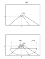
- FIG. 1 shows an example of a camera image IMG and a corresponding light distribution pattern PTN.
- the ADB controller detects the object OBJ in the camera image IMG and determines the position (H, V) of the shaded portion (or dimmed portion) according to its position (x, y).
- the light distribution pattern PTN thus generated includes the light shielding portion SHD at the position (H, V) corresponding to the object OBJ, and can prevent glare.
- the position (H, V) of the light blocking portion SHD also moves following the object OBJ.
- FIG. 2 is a diagram explaining ADB control according to the comparative technique.
- the upper part of FIG. 2 shows the vertical coordinate y of the object OBJ included in the camera image IMG.
- the coordinate y is updated at the frame rate of the camera.
- the frame rate is 30 fps to 60 fps, 120 fps at the fastest, but signal processing for object detection may have a delay of several frames, that is, on the order of several tens of ms. Therefore, in object detection based on camera images, it is difficult to follow fast (for example, 1 Hz to several Hz) positional changes of the object without delay. Therefore, in the comparative technique, it is assumed that the vertical position y of the object OBJ in the camera image IMG does not change on a time scale shorter than 500 ms to 1 s. It generated the vertical position V of the SHD.
- the posture of the vehicle body is kept constant.
- An object in a camera image taken by a vehicle camera that does not change its posture moves relatively fast in the horizontal direction (horizontal direction) in the camera image, but moves slowly in the vertical direction (vertical direction). Tend. Therefore, the coordinate y changes slowly compared to the frame rate.
- the vertical position V of the light shielding portion SHD becomes constant without being affected by the pitching vibration of the vehicle body. Then, following the pitching vibration of the vehicle body, the light shielding portion SHD of the high beam light distribution pattern PTN vibrates up and down.
- FIGS. 3(a) to 3(c) are diagrams for explaining light distribution patterns generated by ADB control according to the comparative technique.
- FIGS. 3A to 3C show light distribution patterns PTN in normal operation, nose-up operation, and nose-down operation (nose dive). Even if pitching vibration occurs, it is not allowed to give glare to the object OBJ. Therefore, in the comparative technique, assuming pitching vibration, it is necessary to set the vertical length (height) ⁇ H of the light shielding portion SHD long by adding a margin to the height of the object OBJ. Even non-existent parts were shaded.
- the light-shielding portion SHD vibrates up and down, causing annoyance to the driver.
- the present disclosure has been made, and one of its exemplary purposes is to provide a lighting system capable of providing an improved field of view to the driver while preventing glare.
- a lighting system includes a variable light distribution lamp that includes a plurality of individually controllable pixels and emits lamp light having a light distribution pattern including a light blocking portion according to the state of the plurality of pixels; a sensor capable of detecting a dynamic component of the pitch angle during running; an optical sensor; of the pixels corresponding to the light-shielded portion are turned off, and the position of the off-pixel group corresponding to the light-shielded portion is set based on the target position of the light-shielded portion according to the dynamic component of the pitch angle of the vehicle body. and a second controller that moves up and down.
- Another aspect of the present disclosure relates to a control method for a variable light distribution lamp that includes a plurality of individually controllable pixels and emits lamp light having a light distribution pattern that includes a light blocking portion according to the state of the plurality of pixels.
- the control method includes the steps of detecting a dynamic component of the pitch angle of the vehicle during travel, detecting an object positioned in front of the vehicle, and generating a target position of the shaded portion based on the position of the object.
- the pixel group corresponding to the light-shielded portion is turned off, and the position of the off-pixel group corresponding to the light-shielded portion is changed based on the target position of the light-shielded portion, based on the dynamic pitch angle of the vehicle body. and moving up and down according to the component.
- FIGS. 3A to 3C are diagrams for explaining light distribution patterns generated by ADB control according to the comparative technique.
- 1 is a block diagram of a lighting system according to an embodiment
- FIGS. 5A and 5B are diagrams for explaining the pitch angle ⁇ p of the vehicle body.
- It is a functional block diagram of a second controller.
- 8 is a diagram showing waveforms of a dynamic pitch angle ⁇ d and a correction amount ⁇ V corresponding to the driving scene of FIG. 7;
- FIGS. 11A to 11C are diagrams for explaining light distribution patterns generated by ADB control according to the embodiment.
- FIG. 8 is a diagram showing light rays corresponding to the boundary between the light shielding portion SHD of the headlamp light and the irradiated portion (that is, the lower end or upper end of the light shielding portion) in the driving scene of FIG. 7 ;
- FIGS. 11A to 11C are diagrams showing examples of the relationship (control characteristics) between the dynamic pitch angle ⁇ d and the correction amount ⁇ V.
- FIG. 10 is a diagram showing a light distribution pattern PTN including a dimming portion;
- a lighting system includes a variable light distribution lamp that includes a plurality of individually controllable pixels and emits light having a light distribution pattern that includes a light blocking portion according to the state of the plurality of pixels; a sensor capable of detecting a dynamic component of the pitch angle during running; an optical sensor; Among the pixels, the pixel group corresponding to the light-shielded portion is turned off, and the position of the off-pixel group corresponding to the light-shielded portion is set based on the target position of the light-shielded portion according to the dynamic component of the pitch angle of the vehicle body. and a second controller for moving up and down.
- the light shielding portion when the rear of the vehicle body sinks (nose up), the light shielding portion is moved downward, and when the front of the vehicle body sinks (nose dive), the light shielding portion moves upward. You can prevent glare by moving.
- the light shielding portion when the vehicle body pitches, the light shielding portion is maintained at the same height with respect to the road surface, so that the sense of discomfort given to the driver can be reduced.
- “light shielding” and “pixels are off” are not limited to cases where the illuminance and brightness are completely zero, and include illuminance and brightness to the extent that glare is not given.
- the second controller may vertically move the ON pixel group corresponding to the illuminated portion surrounding the light shielding portion in conjunction with the OFF pixel group. That is, the entire light distribution formed by the variable light distribution lamp may be moved in the vertical direction.
- the second controller generates dimming information including the target position of the dimming portion based on the output of the optical sensor, and the second controller controls pixels corresponding to the dimming portion among the plurality of pixels.
- the brightness of the group is reduced compared to the ON pixel group, and the position of the pixel group corresponding to the dimmed portion is moved up and down based on the target position of the dimmed portion according to the dynamic component of the pitch angle of the vehicle body. You can move it in any direction.
- the target position of the shaded portion may change at frequencies lower than 5 Hz, and the dynamic component of the pitch angle may include frequencies higher than 0.5 Hz.
- the senor may include a gyro sensor.
- a dynamic pitch angle can be obtained by obtaining an angular velocity in the pitch direction with a gyro sensor and integrating it.
- a state in which member A is connected to member B refers to a case in which member A and member B are physically directly connected, and that member A and member B are electrically connected to each other. It also includes the case of being indirectly connected through other members that do not substantially affect the physical connection state or impair the functions and effects achieved by their combination.
- the state in which member C is provided between member A and member B refers to the case where member A and member C or member B and member C are directly connected, as well as the case where they are electrically connected. It also includes the case of being indirectly connected through other members that do not substantially affect the physical connection state or impair the functions and effects achieved by their combination.
- FIG. 4 is a block diagram of the lamp system 100 according to the embodiment.
- the lighting system 100 is a headlamp that is mounted on a vehicle and illuminates a field of view in front of the vehicle with a beam, and has an ADB (Adaptive Driving Beam) function.
- ADB Adaptive Driving Beam
- the lamp system 100 includes a high-definition lamp unit 110, a sensor 120, an optical sensor 150, a first controller 160 and a second controller 200.
- the high-definition lamp unit 110 is a variable light distribution lamp configured to irradiate part or all of the high beam area, and is also called an ADB lamp.
- the high-definition lamp unit 110 may cover part/all of the low beam area in addition to part/all of the high beam area.
- the high-definition lamp unit 110 includes a plurality of individually controllable pixels PIX, and emits lamp light having a light distribution pattern according to the states of the plurality of pixels PIX.
- high-definition lamp unit 110 includes light-emitting element array 112 and illumination optical system 114 .
- An LED array can be used as the light emitting element array 112 .
- the brightness of each pixel PIX may be controllable with two gradations of ON and OFF, or may be controllable with multiple gradations.
- PWM dimming can be used to achieve multiple gradations. may be expressed.
- the irradiation optical system 114 projects the output light of the light emitting element array 112 forward of the vehicle.
- the irradiation optical system 114 may be a lens optical system, a reflective optical system, or a combination thereof.
- a virtual vertical screen 2 is shown in FIG. It is assumed that the virtual vertical screen 2 is a coordinate system based on the road surface. The distance between the virtual vertical screen 2 and the vehicle (lamp) can be 10m or 25m.
- a high-beam light distribution pattern PTN is formed on the virtual vertical screen 2 by the light from the high-definition lamp unit 110 .
- the light distribution pattern PTN is the intensity distribution of lamp light on the virtual vertical screen 2 and is based on the on/off pattern of the plurality of pixels PIX of the light emitting element array 112 .
- the correspondence between the position of a certain pixel PIX and the illuminated portion on the virtual vertical screen 2 corresponding to that pixel PIX is determined by the illumination optical system 114, and is a mirror image relationship (horizontal inversion), vertical inversion, or vertical inversion. It may be reversed left and right.
- the optical sensor 150 senses the field of view in front of the vehicle.
- the optical sensor 150 can use an optical camera, but other optical sensors such as a LiDAR or ToF camera, a gating camera, or a stereo camera may also be used.
- the first controller 160 determines the position and type of the object OBJ present in front of the vehicle.
- the frame rate of the optical sensor 150 is approximately 30 to 120 fps, and object OBJ detection processing is executed for each frame. Signal processing for object detection may take longer than tens of ms. If the object OBJ should not give glare, for example, an oncoming vehicle or a preceding vehicle, the shading information INFO_SHD including the target position of the shading portion SHD of the light distribution pattern is generated.
- the vertical target position of the shaded portion SHD is generated by filtering the coordinate y of the object OBJ in the image data IMG.
- the position of the shaded portion SHD changes at a rate of 5 Hz or slower.
- the positional information of the shaded portion SHD may indicate the center coordinates of the shaded portion SHD.
- the light shielding portion SHD is rectangular, the coordinates of two diagonal vertices of the light shielding portion SHD may be indicated.
- the vehicle's front-rear tilt angle (vehicle posture) changes according to the front-rear weight balance.
- the inclination angle also changes depending on the unevenness and steps of the road surface while the vehicle is running.
- the tilt angle in the longitudinal direction corresponds to the rotation of the vehicle body about the horizontal axis extending in the left-right direction, and is referred to as the pitch angle (also referred to as the attitude angle) ⁇ p.
- the sensor 120 is provided so as to be able to detect a dynamic component of the pitch angle ⁇ p during running of the vehicle body on which the lighting system 100 is mounted.
- the second controller 200 receives shading information INFO_SHD from the first controller 160 .
- the second controller 200 turns off the pixel group corresponding to the light shielding portion SHD among the plurality of pixels PIX of the light emitting element array 112, and turns on the pixel group corresponding to the irradiated portion other than the light shielding portion in the light distribution pattern of the high beam.
- the second controller 200 detects the dynamic component of the pitch angle ⁇ p of the vehicle body according to the output (detection signal) S1 of the sensor 120.
- the second controller 200 vertically moves the position of the OFF pixel group corresponding to the shaded portion SHD based on the target position obtained from the shaded information INFO_SHD according to the dynamic component of the pitch angle ⁇ p of the vehicle body.
- the high-definition lamp unit 110 and the second controller 200 may be built in the headlamp 510.
- the senor 120 may be provided on the headlamp side or the vehicle side.
- the headlamp side it may be built in the housing (lamp body) of the headlamp, or may be externally attached to the lamp body.
- the vehicle side it may be arranged inside the passenger compartment or outside the passenger compartment, for example, inside the engine room.
- the optical sensor 150 may be provided on the vehicle side, or may be incorporated in the headlamp 510 . If the optical sensor 150 is built into the headlamp, the first controller 160 can also be built into the headlamp 510 . In this case, the first controller 160 and the second controller 200 may be configured with the same hardware.
- the first controller 160 may be provided on the vehicle side.
- the second controller 200 corrects the position of the light shielding portion SHD according to variations in the pitch angle ⁇ p caused by various factors while the vehicle is stationary and running.
- FIGS. 5(a) and 5(b) are diagrams for explaining the pitch angle ⁇ p of the vehicle body.
- FIG. 5(a) shows the pitch angle ⁇ p when the vehicle is stopped.
- the pitch angle ⁇ p when the vehicle is stationary is defined as a static pitch angle ⁇ s. Since the static pitch angle ⁇ s indicates the attitude of the vehicle when the vehicle is stopped, it is also referred to as the stationary vehicle attitude angle.
- the static pitch angle ⁇ s is determined according to the number of passengers, the riding position, the weight of luggage in the luggage compartment, the hardness of the front and rear suspensions, and the like.
- the angle formed by the straight line 12 parallel to the road surface 10 and the reference line 22 of the vehicle body 20 is taken as the pitch angle ⁇ p, and the upward direction of the reference line 22 (nose-up direction) is taken as positive. It is assumed that
- FIG. 5(b) shows the pitch angle ⁇ p while the vehicle is running.
- the pitch angle ⁇ p while the vehicle is running can be grasped as the sum of the static pitch angle ⁇ s and the dynamic component (also referred to as the dynamic pitch angle or pitch angle fluctuation amount) ⁇ d.
- the dynamic pitch angle ⁇ d can include the following components. ⁇ (i) Nose up due to vehicle acceleration, nose down due to deceleration ⁇ (ii) Changes in vehicle weight (weight balance) caused by road surface inclination ⁇ (iii) Fast vehicle vibration caused by uneven road surface
- vibrations of the vehicle body caused by unevenness of the road surface are generally within the range of 0.5 to 5 Hz, although they depend on the hardness of the suspension and the weight of the vehicle.
- a sharp vehicle body vibration is 0.9 to 2 Hz.
- the frequency component of pitch angle fluctuation exceeding 0.5 Hz (approximately 0.5 to 5 Hz, for example 1 to 2 Hz), which was conventionally removed as noise, is not removed as noise, but is corrected.
- the positional correction of the shaded portion for correcting the pitch angle variation during running is referred to as dynamic leveling.
- the sensor 120 is provided so as to detect the dynamic component ⁇ d of the pitch angle ⁇ p while the vehicle body is running.
- the senor 120 includes a gyro sensor.
- the gyro sensor may be attached in any direction, but is preferably installed so that one of its detection axes faces the left-right horizontal direction of the vehicle body, and generates a detection signal S1 indicating the angular velocity ⁇ p of rotational motion around this detection axis.
- the gyro sensor may be triaxial or uniaxial.
- the second controller 200 is an ECU (Electronic Control Unit) that integrates functions related to optical axis correction, and performs processing related to dynamic leveling.
- the second controller 200 may be an ECU dedicated to leveling (also referred to as a leveling ECU), an ECU integrated with a controller having other functions, or divided into a plurality of ECUs. may
- the functions of the second controller 200 may be realized by software processing, hardware processing, or a combination of software processing and hardware processing. Specifically, software processing is implemented by combining processors (hardware) such as CPU (Central Processing Unit), MPU (Micro Processing Unit), and microcontrollers, and software programs executed by the processor (hardware). .
- the second controller 200 may be a combination of multiple processors (microcontrollers).
- hardware processing is implemented by hardware such as ASIC (Application Specific Integrated Circuit), controller IC, and FPGA (Field Programmable Gate Array).
- ASIC Application Specific Integrated Circuit
- controller IC controller IC
- FPGA Field Programmable Gate Array
- the second controller 200 detects the dynamic component ⁇ d of the pitch angle ⁇ p while the vehicle is running by integrating the angular velocity ⁇ p indicated by the detection signal S1.
- the dynamic component ⁇ d here can be regarded as a component included in a predetermined frequency band higher than 0.5 Hz among variations in the pitch angle ⁇ p.
- components included in a predetermined frequency band are subject to correction as dynamic components.
- the predetermined frequency band can be set, for example, within a range of approximately 0.5 Hz to 5 Hz. Which frequency band is to be corrected may be determined based on the stiffness of the suspension, the mass of the vehicle body, and the like.
- the second controller 200 sets the position (position in the vertical direction V) of the light shielding portion SHD of the light distribution pattern PTN to the target indicated by the light shielding information INFO_SHD according to the dynamic component ⁇ d of the pitch angle ⁇ p of the running vehicle body. It is moved upward and/or downward with reference to the position V0 .
- the second controller 200 moves the light shielding portion SHD downward in response to the positive dynamic pitch angle ⁇ d. Conversely, the second controller 200 moves the light blocking portion SHD upward in response to the negative dynamic pitch angle ⁇ d.
- the second controller 200 moves the position of the light shielding portion SHD upward and downward with respect to the predetermined position V0 so as to cancel the dynamic component ⁇ d of the pitch angle ⁇ p.
- the predetermined position V0 is the vertical coordinate at which the light shielding portion SHD should be located when the variation of the pitch angle ⁇ p is zero.
- the second controller 200 changes the positions of the OFF pixel groups of the plurality of pixels PIX of the light emitting element array 112 in order to move the light shielding portion SHD of the light distribution pattern PTN on the virtual vertical screen 2 up and down. How many pixels the OFF pixel group is to be shifted with respect to a certain fluctuation range of the pitch angle ⁇ p can be determined geometrically. Let ⁇ y be the pixel shift amount.
- FIG. 6 is a functional block diagram of the second controller 200.
- the second controller 200 includes a pitch angle calculator 210 and a light blocking position corrector 220 .
- the pitch angle calculator 210 detects the dynamic component ⁇ d of the pitch angle ⁇ p based on the output of the sensor 120 .
- the pitch angle calculator 210 integrates the angular velocity ⁇ p indicated by the detection signal S1.
- the pitch angle calculation unit 210 calculates the dynamic pitch angle ⁇ d by performing calculation processing on the integrated value as necessary. This arithmetic processing can include filtering (band limiting processing), moving average processing, and the like.
- the light shielding position correction unit 220 raises and lowers the position of the light shielding portion SHD based on the dynamic pitch angle ⁇ d.
- the light shielding position corrector 220 includes a correction amount calculator 222 and a corrector 224 .
- the correction amount calculator 222 calculates the vertical movement amount (correction amount ⁇ V) of the light shielding portion SHD on the virtual vertical screen 2 based on the dynamic pitch angle ⁇ d.
- the positive correction amount ⁇ V corresponds to the upward shift of the shaded portion SHD
- the negative correction amount ⁇ V corresponds to the downward shift of the shaded portion SHD.
- the correction unit 224 controls the light emitting element array 112 so that the light shielding portion SHD moves by the correction amount ⁇ V.
- the light-emitting element array 112 has an interface for inputting image data that designates on/off (or luminance) of a plurality of pixels PIX.
- the correction unit 224 may shift the position of the OFF pixel group corresponding to the shaded portion SHD included in the image data up and down by the number of pixels ⁇ y corresponding to the correction amount ⁇ V. That is, the correction unit 224 moves the position of the OFF pixel group of the light distribution pattern included in the image data upward and downward with respect to the predetermined position y0 so as to cancel the dynamic component ⁇ d of the pitch angle ⁇ p.
- the predetermined position y0 is a reference position corresponding to V0 .
- the configuration of the lamp system 100 is as described above. Next, the operation will be explained.
- FIG. 7 is a diagram showing an example of a vehicle traveling scene.
- the vehicle 30 is traveling from left to right on the paper surface, and shows how it climbs over a step 14 on the road surface 10 .
- FIG. 7 shows attitudes of the vehicle 30 at a plurality of times t 0 to t 4 . Each time t 0 to t 4 indicates the following states.
- Time t0 The vehicle is running in front of the step 14
- Time t1 The front wheels have run over the step 14
- Time t2 The front wheels have run over the step 14
- Time t3 The rear wheels have run over the step 14
- State Time t 4 The state where the rear wheels have run over the step 14
- the dynamic pitch angle ⁇ d is 0 at times t 0 , t 2 and t 4 .
- the dynamic pitch angle ⁇ d at time t1 takes a positive value ⁇ d1
- the dynamic pitch angle ⁇ d at time t3 takes a negative value ⁇ d3 .
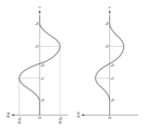
- FIG. 8 is a diagram showing the waveform of the dynamic pitch angle ⁇ d and the waveform of the correction amount ⁇ V corresponding to the driving scene of FIG. As shown in FIG. 7, the dynamic pitch angle ⁇ d swings in the positive direction, then swings in the negative direction, and eventually returns to zero.
- a correction amount ⁇ V is generated corresponding to the variation of the dynamic pitch angle ⁇ d.
- FIGS. 9(a) to 9(c) are diagrams for explaining light distribution patterns generated by ADB control according to the embodiment.
- FIGS. 9A to 9C show the light distribution patterns PTN in the normal state, the nose-up state, and the nose-down state (nose dive).
- the vertical length (height) ⁇ H of the light shielding portion SHD does not require a margin considering the pitching vibration, and the height ⁇ H of the light shielding portion can be made smaller than in the comparison technique.
- the light shielding portion SHD vibrates up and down when the vehicle body pitches, which causes annoyance to the driver. Since it is suppressed, it is possible to suppress the annoyance and discomfort given to the driver.
- each light shielding portion SHD there may be a plurality of light shielding portions SHD, and when there are a plurality of light shielding portions SHD, the vertical position of each light shielding portion SHD is corrected following the variation of the pitch angle.
- FIG. 10 is a diagram showing light rays corresponding to the boundary between the light shielding portion SHD of the headlamp light and the irradiated portion (that is, the lower end or upper end of the light shielding portion) in the driving scene of FIG.
- the light ray 32 at the boundary of the lamp light shielding portion SHD can always be kept at a constant angle with respect to the road surface 10 .
- the lamp system 100 when the rear of the vehicle 30 sinks as shown at time t1 in FIG. 10, glare can be prevented by lowering the light blocking portion SHD. Further, when the front of the vehicle 30 sinks as shown at time t3 in FIG. 10, the glare can be prevented by raising the light shielding portion SHD.
- the light shielding portion SHD on the virtual vertical screen in front of the vehicle is blocked.
- the position can be kept constant at all times, preventing objects in front of the vehicle from brightening or darkening, thus providing an improved field of vision.
- the static pitch angle ⁇ s can be regarded as a reference value of the pitch angle ⁇ p
- the dynamic pitch angle ⁇ d can be regarded as a dynamic deviation from the reference value of the pitch angle ⁇ p. Therefore, the second controller 200 controls the high-definition lamp unit 110 according to the deviation ⁇ d so that the angle formed by the light beam 32 corresponding to the light shielding portion SHD and the road surface 10 is constant. .
- FIGS. 11(a) to 11(c) are diagrams showing examples of the relationship (control characteristics) between the dynamic pitch angle ⁇ d and the correction amount ⁇ V.
- the correction amount ⁇ V is expressed as a linear expression having a proportionality constant (referred to as a reference gain g 0 ) based on the distance L with respect to the dynamic pitch angle ⁇ d. can be determined.
- a reference gain g 0 a proportionality constant
- the illumination optical system 114 is a complex optical system including a reflector having a hyperbolic paraboloid, an elliptical paraboloid, a paraboloid of revolution, and a free paraboloid
- the correction amount ⁇ V may be defined by a polygonal line with respect to the dynamic pitch angle ⁇ d.
- a control characteristic such as (b) may be defined. In this case, it is possible to suppress glare when a control delay occurs in a situation where the nose-up posture is assumed immediately after the nose dive.
- the illumination optical system 114 is a complex optical system that includes a reflecting mirror with an elliptical paraboloid or a free paraboloid, as shown in FIG. may
- the movement of the light shielding portion SHD may be disabled.
- the dynamic pitch angle ⁇ d includes a frequency component that exceeds the response speed of the second controller 200, glare can be suppressed by invalidating the movement of the light blocking portion SHD.
- the pitch angle control may be fixed to the pitch angle control acquired while the vehicle is stopped or in a stable running state. Also, when returning, it is better not to return it immediately, but gradually return it over a period of several seconds. In the case of the high-definition lamp unit 110 capable of controlling the intensity distribution with multiple gradations, it is preferable to apply blurring or gradation to restore the intensity gradually.
- the gyro sensor detects the dynamic component of the pitch angle in the embodiments, the present disclosure is not limited thereto.
- the dynamic component of the pitch angle may be detected based on a combination of a front vehicle height sensor provided on the front suspension of the vehicle body and a rear vehicle height sensor provided on the rear suspension of the vehicle body.
- high definition lamp unit 110 may include a light source that produces light having a substantially flat intensity distribution and a spatial light modulator that spatially patterns the light emitted by the light source.
- Spatial light modulators are exemplified by DMDs (Digital Micromirror Devices) and liquid crystal devices.
- the irradiated portion of the high beam light distribution pattern PTN is fixed and only the light shielding portion SHD is vertically moved, but this is not the only option.
- the second controller 200 vertically moves the ON pixel group corresponding to the illuminated portion surrounding the light shielding portion SHD in conjunction with the OFF pixel group corresponding to the light shielding portion SHD. That is, the entire image data of the light distribution pattern PTN is vertically shifted according to the pitch angle ⁇ p.
- Modification 4 In the embodiment, the generation and correction of the high beam light distribution pattern PTN including the light blocking portion SHD has been described, but the present disclosure can also be applied to a light distribution pattern including a dimming portion.
- FIG. 12 is a diagram showing a light distribution pattern PTN including a dimming portion.
- FIG. 12 shows an example of a camera image IMG and a corresponding light distribution pattern PTN.
- the ADB controller detects objects OBJ 1 -OBJ 3 in the camera image IMG.
- Objects OBJ 1 and OBJ 2 are highly reflective signs, and object OBJ 3 is a pedestrian's head, which are defined as objects to be dimmed.
- the light distribution pattern PTN thus generated includes dimmed portions DIM 1 -DIM 3 at positions corresponding to the objects OBJ 1 -OBJ 3 .
- the objects OBJ 1 and OBJ 2 such as signs with high reflectance the target of the dimming portion DIM, it is possible to suppress glare caused by the reflected light to the driver.
- the object OBJ3 corresponding to the head of a pedestrian or a bicycle driver (referred to as a pedestrian or the like) as the target of the dimming portion DIM, it is possible to prevent the pedestrian or the like from being glared.
- the second controller 200 moves the height-direction positions V 1 to V 3 of the dimming portions DIM 1 to DIM 3 up and down, following the variation of the vehicle body, that is, the variation of the pitch angle. As a result, the vertical relative positional relationship between the objects OBJ 1 to OBJ 3 and the corresponding dimming portions DIM 1 to DIM 3 remains unchanged.
- the method by which the second controller 200 vertically shifts the position of the light shielding portion SHD is not limited to correcting the image data supplied to the light emitting element array 112 .
- the light emitting element array 112 may have a pixel shift function.
- the light-emitting element array 112 may be provided with reference image data and a pixel shift amount ⁇ y.
- the present disclosure relates to vehicle lamps.
- SYMBOLS 100... Lamp system, 110... High definition lamp unit, 112... Light emitting element array, 114... Irradiation optical system, PIX... Pixel, 120... Sensor, 150... Optical sensor, 160... First controller, 200... Second controller, 210 Pitch angle calculation unit 220 Shielding position correction unit 222 Correction amount calculation unit 224 Correction unit 2 Virtual vertical screen.
Landscapes
- Engineering & Computer Science (AREA)
- General Engineering & Computer Science (AREA)
- Physics & Mathematics (AREA)
- Spectroscopy & Molecular Physics (AREA)
- Microelectronics & Electronic Packaging (AREA)
- Optics & Photonics (AREA)
- Mechanical Engineering (AREA)
- Mathematical Physics (AREA)
- Lighting Device Outwards From Vehicle And Optical Signal (AREA)
Abstract
高精細ランプユニット(110)は、個別に制御可能な複数の画素(PIX)を含み、複数の画素(PIX)の状態に応じて、遮光部分(SHD)を含む配光パターン(PTN)を有する灯光を出射する。センサ(120)は、車体の走行中のピッチ角の動的な成分を検出可能に設けられる。第1コントローラ(160)は、光学センサ(150)の出力にもとづいて遮光部分(SHD)の目標位置を含む遮光情報を生成する。第2コントローラ(200)は、複数の画素(PIX)のうち、遮光部分(SHD)に対応する画素群をオフとするとともに、遮光部分(SHD)に対応するオフ画素群の位置を、遮光部分(SHD)の目標位置から、車体のピッチ角の動的な成分に応じて上下方向に移動させる。
Description
本開示は、車両用灯具に関する。
車両用灯具は、一般にロービームとハイビームとを切りかえることが可能である。ロービームは、自車近傍を所定の照度で照明するものであって、対向車や先行車にグレアを与えないよう配光規定が定められており、主に市街地を走行する場合に用いられる。一方、ハイビームは、前方の広範囲および遠方を比較的高い照度で照明するものであり、主に対向車や先行車が少ない道路を高速走行する場合に用いられる。したがって、ハイビームはロービームと比較してより運転者による視認性に優れているが、車両前方に存在する車両の運転者や歩行者にグレアを与えてしまうという問題がある。
近年、車両の周囲の状態にもとづいて、ハイビームの配光パターンを動的、適応的に制御するADB(Adaptive Driving Beam)技術が提案されている。ADB技術は、車両の前方の先行車両、対向車両(前方車両と総称する)、歩行者や標識(以下、物標と総称する)を検出し、車両に対応する領域を、遮光あるいは減光するなどして、車両に与えるグレアを低減するものである。
本発明者らが検討したADB制御を、比較技術として説明する。比較技術に係るADB制御では、車両前方の視野をカメラなどの光学センサでセンシングし、光学センサの出力(たとえばカメラ画像)を処理して、グレアを与えるべきでない物体の位置を検出していた。
図1は、比較技術に係るADB制御を説明する図である。比較技術では、光学センサとしてカメラを用いている。図1には、カメラ画像IMGの一例と、それに対応する配光パターンPTNが示される。ADBコントローラは、カメラ画像IMG内の物体OBJを検出し、その位置(x,y)に応じて、遮光部分(あるいは減光部分)の位置(H,V)を決定する。こうして生成される配光パターンPTNは、物体OBJに対応する位置(H,V)に、遮光部分SHDを含むこととなり、グレアを防止することができる。カメラ画像IMGが更新され、物体OBJのカメラ画像IMG内の位置(x,y)が変化すると、遮光部分SHDの位置(H,V)も物体OBJに追従して移動することとなる。
図2は、比較技術に係るADB制御を説明する図である。図2の上段には、カメラ画像IMGに含まれる物体OBJの垂直方向の座標yが示される。座標yは、カメラのフレームレートで更新される。フレームレートは、30fps~60fps、速いもので120fpsであるが、物体検知のための信号処理には、数フレーム分の、つまり数十msのオーダーの遅延が生ずる場合がある。したがって、カメラ画像にもとづく物体検出では、物体の速い(たとえば1Hz~数Hz)位置変化に無遅延で追従することは難しい。そこで比較技術では、カメラ画像IMG内の物体OBJの垂直方向の位置yは500ms~1sよりも短い時間スケールでは変化しないものと仮定して、時定数が長いフィルタによって座標yを平滑化し、遮光部分SHDの縦方向の位置Vを生成していた。
時刻t0~t1において、車体の姿勢は一定に保たれている。姿勢変動のない車両のカメラが撮影したカメラ画像に写る物体は、カメラ画像内において水平方向(左右方向)には比較的速い速度で移動するが、垂直方向(上下方向)には低速で移動する傾向がある。したがって、座標yは、フレームレートに比べて遅く変化する。
いま、時刻t1~t2において、ピッチング振動したとする。走行中に車体の傾斜角が変動すると、カメラもそれにともなってピッチングする。したがって、カメラ画像内の物体の垂直方向の座標yも振動することとなる。
ところが、上述の平均処理によって、遮光部分SHDの垂直方向の位置Vは、車体のピッチング振動の影響を受けずに一定となる。そうすると、車体のピッチング振動に追従して、ハイビームの配光パターンPTNの遮光部分SHDが上下に振動することとなる。
図3(a)~(c)は、比較技術に係るADB制御により生成される配光パターンを説明する図である。図3(a)~(c)には、通常時、ノーズアップ時、ノーズダウン(ノーズダイブ)それぞれにおける配光パターンPTNが示される。ピッチング振動が発生した場合であっても、物体OBJにグレアを与えることは許されない。そこで比較技術では、ピッチング振動を想定して、遮光部分SHDの垂直方向の長さ(高さ)ΔHを、物体OBJの高さにマージンを付加して長く定めておく必要があり、物体OBJが存在しない部分まで遮光されていた。
加えて、比較技術では、車体がピッチングしたときに、遮光部分SHDが上下に振動するため、運転者に煩わしさを与える原因となっていた。
本開示は係る状況においてなされたものであり、その例示的な目的のひとつは、グレアを防止しつつ、運転者に対して改善された視野を提供可能な灯具システムの提供にある。
本開示のある態様の灯具システムは、個別に制御可能な複数の画素を含み、複数の画素の状態に応じて、遮光部分を含む配光パターンを有する灯光を出射する配光可変ランプと、車体の走行中のピッチ角の動的な成分を検出可能に設けられたセンサと、光学センサと、光学センサの出力にもとづいて遮光部分の目標位置を含む遮光情報を生成する第1コントローラと、複数の画素のうち、遮光部分に対応する画素群をオフとするとともに、遮光部分に対応するオフ画素群の位置を、遮光部分の目標位置を基準として、車体のピッチ角の動的な成分に応じて上下方向に移動させる第2コントローラと、を備える。
本開示の別の態様は、個別に制御可能な複数の画素を含み、複数の画素の状態に応じて、遮光部分を含む配光パターンを有する灯光を出射する配光可変ランプの制御方法に関する。制御方法は、車体の走行中のピッチ角の動的な成分を検出するステップと、車体の前方に位置する物体を検出するステップと、物体の位置にもとづいて遮光部分の目標位置を生成するステップと、複数の画素のうち、遮光部分に対応する画素群をオフとするとともに、遮光部分に対応するオフ画素群の位置を、遮光部分の目標位置を基準として、車体のピッチ角の動的な成分に応じて上下方向に移動させるステップと、を備える。
なお、以上の構成要素を任意に組み合わせたもの、構成要素や表現を、方法、装置、システムなどの間で相互に置換したものもまた、本発明あるいは本開示の態様として有効である。さらに、この項目(課題を解決するための手段)の記載は、本発明の欠くべからざるすべての特徴を説明するものではなく、したがって、記載されるこれらの特徴のサブコンビネーションも、本発明たり得る。
本開示のある態様によれば、グレアを防止しつつ、運転者に対して改善された視野を提供できる。
(実施形態の概要)
本開示のいくつかの例示的な実施形態の概要を説明する。この概要は、後述する詳細な説明の前置きとして、実施形態の基本的な理解を目的として、1つまたは複数の実施形態のいくつかの概念を簡略化して説明するものであり、発明あるいは開示の広さを限定するものではない。またこの概要は、考えられるすべての実施形態の包括的な概要ではなく、実施形態の欠くべからざる構成要素を限定するものではない。便宜上、「一実施形態」は、本明細書に開示するひとつの実施形態(実施例や変形例)または複数の実施形態(実施例や変形例)を指すものとして用いる場合がある。
本開示のいくつかの例示的な実施形態の概要を説明する。この概要は、後述する詳細な説明の前置きとして、実施形態の基本的な理解を目的として、1つまたは複数の実施形態のいくつかの概念を簡略化して説明するものであり、発明あるいは開示の広さを限定するものではない。またこの概要は、考えられるすべての実施形態の包括的な概要ではなく、実施形態の欠くべからざる構成要素を限定するものではない。便宜上、「一実施形態」は、本明細書に開示するひとつの実施形態(実施例や変形例)または複数の実施形態(実施例や変形例)を指すものとして用いる場合がある。
一実施形態に係る灯具システムは、個別に制御可能な複数の画素を含み、複数の画素の状態に応じて、遮光部分を含む配光パターンを有する灯光を出射する配光可変ランプと、車体の走行中のピッチ角の動的な成分を検出可能に設けられたセンサと、光学センサと、光学センサの出力にもとづいて遮光部分の目標位置を含む遮光情報を生成する第1コントローラと、複数の画素のうち、遮光部分に対応する画素群をオフとするとともに、遮光部分に対応するオフ画素群の位置を、遮光部分の目標位置を基準として、車体のピッチ角の動的な成分に応じて上下方向に移動させる第2コントローラと、を備える。
この構成によれば、車体の後方が沈み込んだ場合(ノーズアップ)には、遮光部分を下側に移動し、車体の前方が沈み込んだ場合(ノーズダイブ)には、遮光部分を上側に移動することでグレアを防止できる。また車体がピッチングした場合に、遮光部分が路面に対して同じ高さに維持されるため、運転者に与える違和感を低減できる。なお、「遮光」や「画素がオフである」とは、照度や輝度が完全にゼロである場合に限られず、グレアを与えない程度の照度や輝度を含む。
一実施形態において、第2コントローラは、遮光部分を取り囲む照射部分に対応するオン画素群を、オフ画素群と連動して、上下方向に移動させてもよい。つまり、配光可変ランプが形成する配光全体を、上下方向に移動させてもよい。
一実施形態において、第2コントローラは、光学センサの出力にもとづいて減光部分の目標位置を含む減光情報を生成し、第2コントローラは、複数の画素のうち、減光部分に対応する画素群の輝度を、オン画素群に比べて低下させるとともに、減光部分に対応する画素群の位置を、減光部分の目標位置を基準として、車体のピッチ角の動的な成分に応じて上下方向に移動させてもよい。
遮光部分の目標位置は、5Hzより低い周波数で変化し、ピッチ角の動的な成分は、0.5Hzより高い周波数を含んでもよい。
一実施形態において、センサは、ジャイロセンサを含んでもよい。ジャイロセンサによってピッチ方向の角速度を取得し、それを積分することで、動的なピッチ角を取得することができる。
(実施形態)
以下、好適な実施の形態について図面を参照しながら説明する。各図面に示される同一または同等の構成要素、部材、処理には、同一の符号を付するものとし、適宜重複した説明は省略する。また、実施の形態は、開示を限定するものではなく例示であって、実施の形態に記述されるすべての特徴やその組み合わせは、必ずしも開示の本質的なものであるとは限らない。
以下、好適な実施の形態について図面を参照しながら説明する。各図面に示される同一または同等の構成要素、部材、処理には、同一の符号を付するものとし、適宜重複した説明は省略する。また、実施の形態は、開示を限定するものではなく例示であって、実施の形態に記述されるすべての特徴やその組み合わせは、必ずしも開示の本質的なものであるとは限らない。
本明細書において、「部材Aが、部材Bと接続された状態」とは、部材Aと部材Bが物理的に直接的に接続される場合のほか、部材Aと部材Bが、それらの電気的な接続状態に実質的な影響を及ぼさない、あるいはそれらの結合により奏される機能や効果を損なわせない、その他の部材を介して間接的に接続される場合も含む。
同様に、「部材Cが、部材Aと部材Bの間に設けられた状態」とは、部材Aと部材C、あるいは部材Bと部材Cが直接的に接続される場合のほか、それらの電気的な接続状態に実質的な影響を及ぼさない、あるいはそれらの結合により奏される機能や効果を損なわせない、その他の部材を介して間接的に接続される場合も含む。
図4は、実施形態に係る灯具システム100のブロック図である。灯具システム100は、自動車に搭載され、車両前方の視野をビームで照射するヘッドランプであり、ADB(Adaptive Driving Beam)機能を備える。
灯具システム100は、高精細ランプユニット110、センサ120、光学センサ150、第1コントローラ160および第2コントローラ200を備える。
本実施形態において、高精細ランプユニット110は、ハイビーム領域の一部、または全部を照射可能に構成される配光可変ランプであり、ADBランプとも称する。高精細ランプユニット110は、ハイビーム領域の一部/全部に加えて、ロービーム領域の一部/全部をカバーしてもよい。高精細ランプユニット110は、個別に制御可能な複数の画素PIXを含み、複数の画素PIXの状態に応じた配光パターンを有する灯光を出射する。たとえば高精細ランプユニット110は、発光素子アレイ112と、照射光学系114を含む。発光素子アレイ112としては、LEDアレイを利用することができる。
各画素PIXの輝度は、オン、オフの2階調で制御可能であってもよいし、多階調で制御可能であってもよい。またオン、オフの2階調で制御可能である場合に、各画素PIXを高速にスイッチングし、オン時間とオフ時間の時間比率(デューティサイクル)を変化させることにより、PWM調光によって多階調を表現してもよい。
照射光学系114は、発光素子アレイ112の出力光を、車両の前方に投影する。照射光学系114は、レンズ光学系であってもよいし、反射光学系であってもよいし、それらの組み合わせであってもよい。
図4には、仮想鉛直スクリーン2が示される。仮想鉛直スクリーン2は、路面を基準とした座標系であるとする。仮想鉛直スクリーン2と車両(灯具)との距離は、10mあるいは25mとすることができる。仮想鉛直スクリーン2上には、高精細ランプユニット110の灯光によってハイビームの配光パターンPTNが形成される。配光パターンPTNは、仮想鉛直スクリーン2上における灯光の強度分布であり、発光素子アレイ112の複数の画素PIXのオン、オフのパターンに基づいている。なお、ある画素PIXの位置と、その画素PIXに対応する仮想鉛直スクリーン2上の照射部分の対応は、照射光学系114によって決まるものであり、鏡像の関係(左右反転)あるいは上下反転、あるいは上下左右反転される場合もある。
光学センサ150は、車両前方の視野をセンシングする。光学センサ150は、光学カメラを用いることができるが、その他の光学センサ、たとえばLiDARやToFカメラ、ゲーティングカメラ、ステレオカメラを用いてもよい。
第1コントローラ160は、光学センサ150が生成する画像データIMGにもとづいて、車両前方に存在する物体OBJの位置および種類を判定する。たとえば光学センサ150のフレームレートは30~120fps程度であり、フレーム毎に物体OBJの検出処理が実行される。物体の検出のための信号処理には数十msより長い時間を要する場合がある。そして、物体OBJがグレアを与えるべきでないもの、たとえば、対向車や先行車である場合、配光パターンの遮光部分SHDの目標位置を含む遮光情報INFO_SHDを生成する。遮光部分SHDの上下方向の目標位置は、画像データIMG内の物体OBJの座標yをフィルタリングすることにより生成される。物体検出処理の遅延と、フィルタリングによって、遮光部分SHDの位置は、5Hzまたはそれよりも遅い速度で変化することとなる。遮光部分SHDの位置情報は、遮光部分SHDの中心座標を示してもよい。遮光部分SHDが矩形の場合には、遮光部分SHDの対角の2頂点の座標を示してもよい。
自動車は、前後の重量バランスに応じて、前後方向の傾斜角(車両姿勢)が変化する。また走行中の路面の凹凸や段差によっても、傾斜角は変化する。前後方向の傾斜角は、車体の左右に伸びる水平軸周りの回転に応じており、ピッチ角(姿勢角ともいう)θpと称する。センサ120は、灯具システム100を搭載する車体の走行中のピッチ角θpの動的な成分を検出可能に設けられる。
第2コントローラ200は、第1コントローラ160から遮光情報INFO_SHDを受ける。第2コントローラ200は、発光素子アレイ112の複数の画素PIXのうち、遮光部分SHDに対応する画素群をオフとし、ハイビームの配光パターン内の遮光部分以外の照射部分に対応する画素群をオンとする。
第2コントローラ200は、センサ120の出力(検出信号)S1に応じて、車体のピッチ角θpの動的な成分を検出する。第2コントローラ200は、遮光部分SHDに対応するオフ画素群の位置を、遮光情報INFO_SHDから得た目標位置を基準として、車体のピッチ角θpの動的な成分に応じて上下方向に移動させる。
高精細ランプユニット110および第2コントローラ200は、ヘッドランプ510に内蔵してもよい。
たとえばセンサ120は、ヘッドランプ側に設けてもよいし、車両側に設けてもよい。ヘッドランプ側の場合、ヘッドランプの筐体(ランプボディ)に内蔵してもよいし、ランプボディに外付けしてもよい。車両側の場合、車室内に配置してもよいし、車室外、たとえばエンジンルーム内に配置してもよい。また光学センサ150は、車両側に設けてもよいし、ヘッドランプ510に内蔵してもよい。光学センサ150をヘッドランプに内蔵する場合、第1コントローラ160もヘッドランプ510に内蔵することができる。この場合、第1コントローラ160と第2コントローラ200は、同じハードウェアで構成してもよい。光学センサ150を車両側に設ける場合、第1コントローラ160は車両側に設けてもよい。
本実施形態では、第2コントローラ200は、車両静止中および走行中のさまざまな要因に起因するピッチ角θpの変動に応じて、遮光部分SHDの位置を補正する。
図5(a)、(b)は、車体のピッチ角θpを説明する図である。図5(a)には、車両が停止した状態でのピッチ角θpが示される。車両の静止状態におけるピッチ角θpを、静的ピッチ角θsとする。静的ピッチ角θsは、車両停止時の車両の姿勢を示すから、停止車両姿勢角ともいう。静的ピッチ角θsは、乗車人数や乗車位置、荷室内の荷物の重量、前後のサスペンションの固さなどに応じて決まる。本実施形態は、路面10と平行な直線12と、車体20の基準線22とがなす角度を、ピッチ角θpととり、基準線22が上を向く方向(ノーズアップの方向)を正にとることとする。
図5(b)には、車両の走行中のピッチ角θpが示される。車両走行中のピッチ角θpは、静的ピッチ角θsと、動的な成分(動的ピッチ角、あるいはピッチ角の変動量ともいう)θdの合計と把握することができる。動的ピッチ角θdは、以下の成分を含みうる。
・(i)車体の加速にともなうノーズアップ、減速にともなうノーズダウン
・(ii)路面の傾斜など起因する車体の加重(重量バランス)の変化
・(iii)路面の凹凸に起因する速い車体の振動
・(i)車体の加速にともなうノーズアップ、減速にともなうノーズダウン
・(ii)路面の傾斜など起因する車体の加重(重量バランス)の変化
・(iii)路面の凹凸に起因する速い車体の振動
(i)車体の加減速にともなうピッチ角変動、あるいは(ii)車体の加重変化にともなうピッチ角変化は、数秒にわたり持続するため、典型的には直流的な変動であり、周波数成分が非常に低いといえる(0.5Hz以下)。
これに対して、(iii)路面の凹凸に起因する車体の振動は、サスペンションの固さや車重にも依存するが、概ね0.5~5Hz程度の範囲に含まれる。一例として、急峻な車体振動は、0.9~2Hzである。
本実施形態では、従来ノイズとして除去していたピッチ角変動の0.5Hzを超える周波数成分(概ね0.5~5Hz,たとえば1~2Hz)をノイズとして除去せずに、補正の対象としている。本明細書において、走行中のピッチ角変動を補正するための、遮光部分の位置補正を、ダイナミックレベリングと称する。
図4に戻る。以下では、ダイナミックレベリング、特に路面の凹凸に起因する高速なピッチ角変動に対するレベリングについて詳細に説明する。センサ120は、車体の走行中のピッチ角θpの動的な成分θdを検出できるように設けられる。
本実施形態において、センサ120はジャイロセンサを含む。ジャイロセンサの取り付ける方向は任意であるが、好ましくはその一つの検出軸が車体の左右水平方向を向くように取り付けられ、この検出軸まわりの回転運動の角速度ωpを示す検出信号S1を生成する。ジャイロセンサは三軸であってもよいし、一軸であってもよい。
第2コントローラ200は、光軸の補正に関連する機能が集約されたECU(Electronic Control Unit)であり、ダイナミックレベリングに関する処理を行う。第2コントローラ200は、レベリング専用のECU(レベリングECUともいう)であってもよいし、その他の機能を有するコントローラと統合されたECUであってもよいし、複数のECUに分割して構成してもよい。
第2コントローラ200の機能は、ソフトウェア処理で実現してもよいし、ハードウェア処理で実現してもよいし、ソフトウェア処理とハードウェア処理の組み合わせで実現してもよい。ソフトウェア処理は、具体的には、CPU(Central Processing Unit)、MPU(Micro Processing Unit)、マイクロコントローラなどのプロセッサ(ハードウェア)と、プロセッサ(ハードウェア)が実行するソフトウェアプログラムの組み合わせで実装される。第2コントローラ200は、複数のプロセッサ(マイクロコントローラ)の組み合わせであってもよい。
ハードウェア処理は具体的には、ASIC(Application Specific Integrated Circuit)やコントローラIC、FPGA(Field Programmable Gate Array)などのハードウェアで実装される。
第2コントローラ200は、検出信号S1が示す角速度ωpを積分することにより、車両走行中のピッチ角θpの動的な成分θdを検出する。ここでの動的な成分θdは、ピッチ角θpの変動のうち、0.5Hzより高い所定の周波数帯域に含まれる成分と捉えることができる。たとえば、ピッチ角θpの変動のうち、所定の周波数帯域に含まれる成分を、動的な成分として補正対象とする。所定の周波数帯域は、たとえば0.5Hz~5Hz程度の範囲に定めることができる。どの周波数帯域を補正対象とするかは、サスペンションの固さや車体質量などにもとづいて決めればよい。
そして第2コントローラ200は、走行中の車体のピッチ角θpの動的な成分θdに応じて、配光パターンPTNの遮光部分SHDの位置(垂直方向Vの位置)を、遮光情報INFO_SHDが示す目標位置V0を基準として上方向および/または下方向に移動させる。
第2コントローラ200は、正の動的ピッチ角θdに対応して、遮光部分SHDを下方向に移動させる。反対に第2コントローラ200は、負の動的ピッチ角θdに対応して、遮光部分SHDを上方向に移動させる。
より詳しくは第2コントローラ200は、ピッチ角θpの動的な成分θdを打ち消すように、遮光部分SHDの位置を、所定位置V0を基準として上方向および下方向に移動させる。所定位置V0は、ピッチ角θpの変動がゼロであるときに、遮光部分SHDが位置すべき垂直方向の座標である。
第2コントローラ200は、仮想鉛直スクリーン2上の配光パターンPTNの遮光部分SHDを上下させるために、発光素子アレイ112の複数の画素PIXのオフ画素群の位置を変化させる。ピッチ角θpのある変動幅に対して、オフ画素群を何ピクセルシフトさせるかは、幾何光学的に決めることができる。ピクセルのシフト量をΔyとする。
図6は、第2コントローラ200の機能ブロック図である。第2コントローラ200は、ピッチ角演算部210と、遮光位置補正部220と、を備える。
ピッチ角演算部210は、センサ120の出力にもとづいて、ピッチ角θpの動的な成分θdを検出する。たとえばピッチ角演算部210は、検出信号S1が示す角速度ωpを積分する。さらにピッチ角演算部210は、必要に応じて、積分値に演算処理を施して、動的ピッチ角θdを算出する。この演算処理は、フィルタ処理(帯域制限処理)や、移動平均処理などを含むことができる。
遮光位置補正部220は、動的ピッチ角θdにもとづいて、遮光部分SHDの位置を上下させる。遮光位置補正部220は、補正量演算部222および補正部224を含む。補正量演算部222は、動的ピッチ角θdにもとづいて、仮想鉛直スクリーン2上の遮光部分SHDの上下方向の移動量(補正量ΔV)を算出する。本実施形態では、正の補正量ΔVは、遮光部分SHDの上方向へのシフトに対応し、負の補正量ΔVは、遮光部分SHDの下方向へのシフトに対応するものとする。補正部224は、遮光部分SHDが補正量ΔVだけ移動するように、発光素子アレイ112を制御する。
たとえば、発光素子アレイ112は、複数の画素PIXのオン、オフ(もしくは輝度)を指定する画像データを入力とするインタフェースを有する。この場合、補正部224は、画像データに含まれる遮光部分SHDに対応するオフ画素群の位置を、補正量ΔVに応じたピクセル数Δyだけ、上下にシフトしてもよい。つまり補正部224は、ピッチ角θpの動的な成分θdを打ち消すように、画像データに含まれる配光パターンのオフ画素群の位置を、所定位置y0を基準として上方向および下方向に移動させる。所定位置y0は、V0に対応する基準位置である。
以上が灯具システム100の構成である。続いてその動作を説明する。
図7は、車両の走行シーンの一例を示す図である。この例では、車両30は紙面左から右に向かって走行しており、路面10上の段差14を乗り越える様子を示している。図7には、複数の時刻t0~t4における車両30の姿勢が示される。各時刻t0~t4は以下の状態を示す。
時刻t0: 段差14の手前を走行している状態
時刻t1: 段差14に前輪が乗り上げた状態
時刻t2: 前輪が段差14を乗り越えた状態
時刻t3: 後輪が段差14に乗り上げた状態
時刻t4: 後輪が段差14を乗り越えた状態
時刻t1: 段差14に前輪が乗り上げた状態
時刻t2: 前輪が段差14を乗り越えた状態
時刻t3: 後輪が段差14に乗り上げた状態
時刻t4: 後輪が段差14を乗り越えた状態
時刻t0、t2、t4それぞれにおける動的ピッチ角θdは0である。時刻t1における動的ピッチ角θdは正の値θd1をとり、時刻t3における動的ピッチ角θdは負の値θd3をとる。
図8は、図7の走行シーンに対応する動的ピッチ角θdの波形と、補正量ΔVの波形を示す図である。図7に示すように、動的ピッチ角θdは、正方向に振れた後、負方向に振れ、やがて0に戻る。
この動的ピッチ角θdの変動に対応して、補正量ΔVが生成される。
図9(a)~(c)は、実施形態に係るADB制御により生成される配光パターンを説明する図である。図9(a)~(c)には、通常時、ノーズアップ時、ノーズダウン(ノーズダイブ)それぞれにおける配光パターンPTNが示される。本実施形態によれば、ピッチング振動が発生した場合であっても、遮光部分SHDと物体OBJの位置関係は変化しない。したがって、遮光部分SHDの垂直方向の長さ(高さ)ΔHに、ピッチング振動を考慮したマージンが不要となり、遮光部分の高さΔHを比較技術に比べて小さくできる。
また加えて、比較技術では、車体がピッチングしたときに、遮光部分SHDが上下に振動するため、運転者に煩わしさを与える原因となっていたが、本実施形態では、遮光部分SHDの振動が抑制されるため、運転者に与える煩わしさや違和感を抑制できる。
なお、遮光部分SHDは複数であってもよく、遮光部分SHDが複数の場合は、それぞれについて、縦方向の位置が、ピッチ角の変動に追従して補正される。
図10は、図7の走行シーンにおけるヘッドランプの灯光の遮光部分SHDと照射部分の境界(つまり遮光部分の下端もしくは上端)に対応する光線を示す図である。動的ピッチ角θdに追従した適応的な配光制御によって、灯光の遮光部SHDの境界の光線32を、常に路面10に対して一定の角度に保つことができる。
以上が灯具システム100の動作である。この灯具システム100によれば、図10の時刻t1に示すように、車両30の後方が沈み込んだ場合には、遮光部分SHDを下側に下げることでグレアを防止できる。また、図10の時刻t3に示すように、車両30の前方が沈み込んだ場合には、遮光部分SHDを上側に上げることで、グレアを防止できる。
また、この制御を車体のピッチ角θの動的な変動に追従して行うことで、車両30が前後方向に振動(ピッチング)した場合においても、車両前方の仮想鉛直スクリーン上の遮光部分SHDの位置を常に一定に保つことができ、車両前方の物体が明るくなったり暗くなったりするのを防止でき、ひいては改善された視野を提供できる。
静的ピッチ角θsは、ピッチ角θpの基準値と捉えることができ、動的ピッチ角θdは、ピッチ角θpの基準値からの動的なずれと把握できる。したがって第2コントローラ200は、当該ずれθdに応じて、灯光の遮光部分SHDに対応する光線32と路面10のなす角度が一定となるように、高精細ランプユニット110を制御していることになる。
以下では、第2コントローラ200によるピッチ角θpの変動に追従した配光制御の例を説明する。
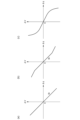
図11(a)~(c)は、動的ピッチ角θdと補正量ΔVの関係(制御特性)の例を示す図である。
補正量ΔVを、仮想鉛直スクリーン上の遮光部分SHDの移動量とし、仮想鉛直スクリーンまでの距離をLとするとき、式(1)が成り立てばよい。
ΔV=L×tanθd …(1)
θd≒0のとき、tanθd≒θdであるから、式(2)を得る。
ΔV≒L×θd …(2)
ΔV=L×tanθd …(1)
θd≒0のとき、tanθd≒θdであるから、式(2)を得る。
ΔV≒L×θd …(2)
したがって、最も簡易には、図11(a)に示すように、補正量ΔVは、動的ピッチ角θdに対して、距離Lにもとづく比例定数(基準ゲインg0という)を有する1次式として定めることができる。上述したように、発光素子アレイ112に供給する画像データを修正する場合、図7この補正量ΔVが得られるように、画像データ上の遮光部分SHDに対応するオフ画素群を上下方向にシフトする。このときのピクセルのシフト量Δyは、照射光学系114の照射光学系114の設計にもとづいて定めることができ、幾何光学的に求まる関数f()を用いて、Δy=f(θd)の関係が成り立つ。照射光学系114が単純な光学系である場合、f()は一次関数で近似でき、式(3)で表すことができる。
Δy=α・θd …(3)
Δy=α・θd …(3)
照射光学系114が、双曲放物面、楕円放物面、回転放物面、自由放物面を有する反射鏡を含むような複雑な光学系である場合には、図11(b)に示すように、補正量ΔVを、動的ピッチ角θdに対する折れ線で規定してもよい。
あるいは、単純な光学系を用いる場合であっても、変動量(θdの絶対値)が大きな領域において、動的ピッチ角θdの単位変動量に対する補正量ΔVを小さくすることを目的として、図11(b)のような制御特性を定めてもよい。この場合、ノーズダイブの直後にノーズアップの姿勢となる状況において、制御遅延が生じた場合に、グレアを与えるのを抑制できる。
照射光学系114が、楕円放物面や自由放物面を有する反射鏡を含むような複雑な光学系である場合には、図11(c)に示すように、より複雑な制御特性を定めてもよい。
走行状況に応じて、遮光部分SHDの移動を無効化してもよい。たとえば、動的ピッチ角θdが、第2コントローラ200が有する応答速度を超えるような周波数成分を含んでいる場合には、遮光部分SHDの移動を無効化することで、グレアを抑制できる。
また、路面凹凸が連続的に(例えば、時間にして3秒以上)発生している場合、通常の道路の走行と異なる特殊な路面(例えば、ダートコースや、未舗装の山道等)と想定される。そこで、所定時間(たとえば3秒)以上、連続的に急峻なピッチ角変化が起きている時は、停車状態又は安定走行状態において取得したピッチ角制御に固定してもよい。また戻す際には、即座に戻すのではなく、数秒の時間を掛けて徐々に戻すとよい。多階調で強度分布を制御可能な高精細ランプユニット110の場合、ボカシやグラデーションをかけて徐々に戻すとよい。
(変形例)
実施形態は例示であり、さまざまな変形例が存在する。以下では、灯具システム100の変形例を説明する。
実施形態は例示であり、さまざまな変形例が存在する。以下では、灯具システム100の変形例を説明する。
(変形例1)
実施形態では、ジャイロセンサによって、ピッチ角の動的な成分を検出したが、本開示はそれに限定されない。たとえば車体のフロントサスペンションに設けられたフロント車高センサと、車体のリアサスペンションに設けられたリア車高センサの組み合わせにもとづいて、ピッチ角の動的な成分を検出するようにしてもよい。
実施形態では、ジャイロセンサによって、ピッチ角の動的な成分を検出したが、本開示はそれに限定されない。たとえば車体のフロントサスペンションに設けられたフロント車高センサと、車体のリアサスペンションに設けられたリア車高センサの組み合わせにもとづいて、ピッチ角の動的な成分を検出するようにしてもよい。
(変形例2)
実施形態では、高精細ランプユニット110を発光素子アレイ112で構成したが本開示はそれに限定されない。たとえば高精細ランプユニット110は、実質的にフラットな強度分布を有する光を生成する光源と、光源の出射光を空間的にパターニングする空間光変調器と、を含んでもよい。空間光変調器は、DMD(Digital Micromirror Device)や、液晶デバイスなどが例示される。
実施形態では、高精細ランプユニット110を発光素子アレイ112で構成したが本開示はそれに限定されない。たとえば高精細ランプユニット110は、実質的にフラットな強度分布を有する光を生成する光源と、光源の出射光を空間的にパターニングする空間光変調器と、を含んでもよい。空間光変調器は、DMD(Digital Micromirror Device)や、液晶デバイスなどが例示される。
(変形例3)
実施形態では、ハイビームの配光パターンPTNの照射部分を固定して、遮光部分SHDのみを上下に移動したが、その限りでない。第2コントローラ200は、遮光部分SHDを取り囲む照射部分に対応するオン画素群を、遮光部分SHDに対応するオフ画素群と連動して、上下方向に移動させる。つまり配光パターンPTNの画像データ全体を、ピッチ角θpに応じて上下にシフトさせる。
実施形態では、ハイビームの配光パターンPTNの照射部分を固定して、遮光部分SHDのみを上下に移動したが、その限りでない。第2コントローラ200は、遮光部分SHDを取り囲む照射部分に対応するオン画素群を、遮光部分SHDに対応するオフ画素群と連動して、上下方向に移動させる。つまり配光パターンPTNの画像データ全体を、ピッチ角θpに応じて上下にシフトさせる。
(変形例4)
実施形態では、遮光部分SHDを含むハイビームの配光パターンPTNの生成および補正について説明したが、減光部分を含む配光パターンにも、本開示は適用できる。
実施形態では、遮光部分SHDを含むハイビームの配光パターンPTNの生成および補正について説明したが、減光部分を含む配光パターンにも、本開示は適用できる。
図12は、減光部分を含む配光パターンPTNを示す図である。図12には、カメラ画像IMGの一例と、それに対応する配光パターンPTNが示される。ADBコントローラは、カメラ画像IMG内の物体OBJ1~OBJ3を検出する。物体OBJ1、OBJ2は反射率が高い標識であり、物体OBJ3は歩行者の頭部であり、これらは減光すべき対象として規定されている。第1コントローラ160は、物体OBJi(i=1,2,3)それぞれの位置(xi,yi)に応じて、減光部分DIMの位置(Hi,Vi)を決定する。こうして生成される配光パターンPTNは、物体OBJ1~OBJ3に対応する位置に、減光部分DIM1~DIM3を含む。
反射率が高い標識などの物体OBJ1,OBJ2を減光部分DIMの対象とすることで、運転者に反射光によるグレアを与えるのを抑制できる。また歩行者や自転車の運転者(歩行者等という)の頭部に対応する物体OBJ3を減光部分DIMの対象とすることで、歩行者等にグレアを与えるのを防止できる。
第2コントローラ200は、車体の変動、つまりピッチ角の変動に追従して、減光部分DIM1~DIM3それぞれの高さ方向の位置V1~V3を上下に移動させる。これにより、常に物体OBJ1~OBJ3と、対応する減光部分DIM1~DIM3の上下方向の相対的な位置関係は不変となる。
減光部分DIMについて、車体の振動にともなう位置補正を行わない場合を考える。反射率が高い物体OBJj(j=1,2)と減光部分DIMjの上下方向の相対的な位置関係が、車体のピッチングに応じて変化すると、自車の運転者から見たときに、物体OBJjの上を、減光部分DIMjが上下に往復する。この往復の過程で、減光部分DIMjの上下に隣接する照射部分によって、物体OBJjが照射され、自車の運転者は、反射光によるグレアを受けることとなる。また物体OBJjに対する灯光の照度が時間的に変化するため、運転者は煩わしさを感じることとなる。変形例4によれば、減光部分DIMjについても、車体のピッチングに応じて位置を補正することにより、このような問題を解決できる。
また歩行者の頭部である物体OBJ3と減光部分DIM3の上下方向の相対的な位置関係が、車体のピッチングに応じて変化すると、歩行者等にグレアを与えることとなる。これに対して、変形例4によれば、減光部分DIM3についても、車体のピッチングに応じて位置を補正することにより、歩行者等に与えるグレアを抑制できる。
(変形例5)
第2コントローラ200が、遮光部分SHDの位置を上下方向にシフトさせる手法は、発光素子アレイ112に供給する画像データを修正するものに限定されない。たとえば、発光素子アレイ112がピクセルシフト機能を有してもよい。この場合、発光素子アレイ112に対して、基準となる画像データと、ピクセルシフト量Δyを与えればよい。
第2コントローラ200が、遮光部分SHDの位置を上下方向にシフトさせる手法は、発光素子アレイ112に供給する画像データを修正するものに限定されない。たとえば、発光素子アレイ112がピクセルシフト機能を有してもよい。この場合、発光素子アレイ112に対して、基準となる画像データと、ピクセルシフト量Δyを与えればよい。
実施の形態にもとづき、具体的な語句を用いて本開示を説明したが、実施の形態は、本開示の原理、応用を示しているにすぎず、実施の形態には、請求の範囲に規定された本開示の思想を逸脱しない範囲において、多くの変形例や配置の変更が認められる。
本開示は、車両用灯具に関する。
100…灯具システム、110…高精細ランプユニット、112…発光素子アレイ、114…照射光学系、PIX…画素、120…センサ、150…光学センサ、160…第1コントローラ、200…第2コントローラ、210…ピッチ角演算部、220…遮光位置補正部、222…補正量演算部、224…補正部、2…仮想鉛直スクリーン。
Claims (6)
- 個別に制御可能な複数の画素を含み、前記複数の画素の状態に応じて、遮光部分を含む配光パターンを有する灯光を出射する配光可変ランプと、
車体の走行中のピッチ角の動的な成分を検出可能に設けられたセンサと、
光学センサと、
前記光学センサの出力にもとづいて前記遮光部分の目標位置を含む遮光情報を生成する第1コントローラと、
前記複数の画素のうち、前記遮光部分に対応する画素群をオフとするとともに、前記遮光部分に対応するオフ画素群の位置を、前記遮光部分の前記目標位置を基準として、前記車体のピッチ角の動的な成分に応じて上下方向に移動させる第2コントローラと、
を備えることを特徴とする灯具システム。 - 前記第2コントローラは、前記遮光部分を取り囲む照射部分に対応するオン画素群を、前記オフ画素群と連動して、上下方向に移動させることを特徴とする請求項1に記載の灯具システム。
- 前記第2コントローラは、前記光学センサの出力にもとづいて減光部分の目標位置を含む減光情報を生成し、
前記第2コントローラは、前記複数の画素のうち、前記減光部分に対応する画素群の輝度を、オン画素群に比べて低下させるとともに、前記減光部分に対応する画素群の位置を、前記減光部分の前記目標位置を基準として、前記車体のピッチ角の動的な成分に応じて上下方向に移動させることを特徴とする請求項1または2に記載の灯具システム。 - 前記遮光部分の目標位置は、5Hzより低い周波数で変化し、前記ピッチ角の動的な成分は、0.5Hzより高い周波数を含むことを特徴とする請求項1から3のいずれかに記載の灯具システム。
- 前記センサは、ジャイロセンサを含むことを特徴とする請求項1から4のいずれかに記載の灯具システム。
- 個別に制御可能な複数の画素を含み、前記複数の画素の状態に応じて、遮光部分を含む配光パターンを有する灯光を出射する配光可変ランプの制御方法であって、
車体の走行中のピッチ角の動的な成分を検出するステップと、
車体の前方に位置する物体を検出するステップと、
前記物体の位置にもとづいて前記遮光部分の目標位置を生成するステップと、
前記複数の画素のうち、前記遮光部分に対応する画素群をオフとするとともに、前記遮光部分に対応するオフ画素群の位置を、前記遮光部分の前記目標位置を基準として、前記車体のピッチ角の動的な成分に応じて上下方向に移動させるステップと、
を備えることを特徴とする制御方法。
Priority Applications (1)
| Application Number | Priority Date | Filing Date | Title |
|---|---|---|---|
| JP2023562354A JPWO2023090331A1 (ja) | 2021-11-19 | 2022-11-15 |
Applications Claiming Priority (2)
| Application Number | Priority Date | Filing Date | Title |
|---|---|---|---|
| JP2021-188628 | 2021-11-19 | ||
| JP2021188628 | 2021-11-19 |
Publications (1)
| Publication Number | Publication Date |
|---|---|
| WO2023090331A1 true WO2023090331A1 (ja) | 2023-05-25 |
Family
ID=86397100
Family Applications (1)
| Application Number | Title | Priority Date | Filing Date |
|---|---|---|---|
| PCT/JP2022/042450 Ceased WO2023090331A1 (ja) | 2021-11-19 | 2022-11-15 | 灯具システムおよびランプの制御方法 |
Country Status (2)
| Country | Link |
|---|---|
| JP (1) | JPWO2023090331A1 (ja) |
| WO (1) | WO2023090331A1 (ja) |
Cited By (1)
| Publication number | Priority date | Publication date | Assignee | Title |
|---|---|---|---|---|
| WO2025159052A1 (ja) * | 2024-01-24 | 2025-07-31 | 株式会社小糸製作所 | 配光可変ランプの制御装置、車両用灯具、ソフトウェアプログラム |
Citations (2)
| Publication number | Priority date | Publication date | Assignee | Title |
|---|---|---|---|---|
| JP2004071409A (ja) * | 2002-08-07 | 2004-03-04 | Denso Corp | 車両用灯具および車両用灯具の配光制御方法 |
| JP2019038279A (ja) * | 2017-08-22 | 2019-03-14 | スタンレー電気株式会社 | 車両用灯具の制御装置、車両用灯具システム |
-
2022
- 2022-11-15 JP JP2023562354A patent/JPWO2023090331A1/ja active Pending
- 2022-11-15 WO PCT/JP2022/042450 patent/WO2023090331A1/ja not_active Ceased
Patent Citations (2)
| Publication number | Priority date | Publication date | Assignee | Title |
|---|---|---|---|---|
| JP2004071409A (ja) * | 2002-08-07 | 2004-03-04 | Denso Corp | 車両用灯具および車両用灯具の配光制御方法 |
| JP2019038279A (ja) * | 2017-08-22 | 2019-03-14 | スタンレー電気株式会社 | 車両用灯具の制御装置、車両用灯具システム |
Cited By (1)
| Publication number | Priority date | Publication date | Assignee | Title |
|---|---|---|---|---|
| WO2025159052A1 (ja) * | 2024-01-24 | 2025-07-31 | 株式会社小糸製作所 | 配光可変ランプの制御装置、車両用灯具、ソフトウェアプログラム |
Also Published As
| Publication number | Publication date |
|---|---|
| JPWO2023090331A1 (ja) | 2023-05-25 |
Similar Documents
| Publication | Publication Date | Title |
|---|---|---|
| US10369922B2 (en) | Vehicle headlight device | |
| US20200369200A1 (en) | Vehicle detecting device and vehicle lamp system | |
| CN110709281B (zh) | 车辆用灯具及其控制装置、控制方法 | |
| US12503038B2 (en) | Lamp system | |
| WO2023090331A1 (ja) | 灯具システムおよびランプの制御方法 | |
| US12358417B2 (en) | Lamp system | |
| US20240302018A1 (en) | Lamp system | |
| CN120677087A (zh) | 车辆用灯具系统、配光可变灯的控制器、控制方法、程序 | |
| US20250326350A1 (en) | Vehicle lamp apparatus | |
| JP2025179887A (ja) | 制御装置、車両用灯具システム、およびソフトウェアプログラム | |
| US20250297719A1 (en) | Vehicle lamp | |
| WO2023090328A1 (ja) | 灯具システム | |
| EP4635797A1 (en) | Vehicle lamp and vehicle lamp system | |
| WO2024195545A1 (ja) | 灯具システムおよびランプのコントローラおよび制御方法 | |
| WO2025079504A1 (ja) | 車両用灯具、配光可変ランプの制御装置、ソフトウェアプログラム | |
| CN118284541A (zh) | 灯具系统 | |
| CN121986038A (en) | Vehicle lamp, control device for variable light distribution, and software program | |
| JP7152511B2 (ja) | 光学素子、それを用いた車両用前照灯ユニット、及び、車両用前照灯装置 | |
| WO2024203680A1 (ja) | 配光可変ランプの制御装置、車両用灯具、ソフトウェアプログラム | |
| WO2025159052A1 (ja) | 配光可変ランプの制御装置、車両用灯具、ソフトウェアプログラム |
Legal Events
| Date | Code | Title | Description |
|---|---|---|---|
| 121 | Ep: the epo has been informed by wipo that ep was designated in this application |
Ref document number: 22895612 Country of ref document: EP Kind code of ref document: A1 |
|
| ENP | Entry into the national phase |
Ref document number: 2023562354 Country of ref document: JP Kind code of ref document: A |
|
| NENP | Non-entry into the national phase |
Ref country code: DE |
|
| 122 | Ep: pct application non-entry in european phase |
Ref document number: 22895612 Country of ref document: EP Kind code of ref document: A1 |