WO2023089670A1 - 回転電機の回転子 - Google Patents
回転電機の回転子 Download PDFInfo
- Publication number
- WO2023089670A1 WO2023089670A1 PCT/JP2021/042124 JP2021042124W WO2023089670A1 WO 2023089670 A1 WO2023089670 A1 WO 2023089670A1 JP 2021042124 W JP2021042124 W JP 2021042124W WO 2023089670 A1 WO2023089670 A1 WO 2023089670A1
- Authority
- WO
- WIPO (PCT)
- Prior art keywords
- rotor
- electric machine
- magnet
- outermost diameter
- rotary electric
- Prior art date
- Legal status (The legal status is an assumption and is not a legal conclusion. Google has not performed a legal analysis and makes no representation as to the accuracy of the status listed.)
- Ceased
Links
Images


Classifications
-
- H—ELECTRICITY
- H02—GENERATION; CONVERSION OR DISTRIBUTION OF ELECTRIC POWER
- H02K—DYNAMO-ELECTRIC MACHINES
- H02K1/00—Details of the magnetic circuit
- H02K1/06—Details of the magnetic circuit characterised by the shape, form or construction
- H02K1/22—Rotating parts of the magnetic circuit
- H02K1/27—Rotor cores with permanent magnets
- H02K1/2706—Inner rotors
- H02K1/272—Inner rotors the magnetisation axis of the magnets being perpendicular to the rotor axis
- H02K1/274—Inner rotors the magnetisation axis of the magnets being perpendicular to the rotor axis the rotor consisting of two or more circumferentially positioned magnets
- H02K1/2753—Inner rotors the magnetisation axis of the magnets being perpendicular to the rotor axis the rotor consisting of two or more circumferentially positioned magnets the rotor consisting of magnets or groups of magnets arranged with alternating polarity
- H02K1/276—Magnets embedded in the magnetic core, e.g. interior permanent magnets [IPM]
-
- H—ELECTRICITY
- H02—GENERATION; CONVERSION OR DISTRIBUTION OF ELECTRIC POWER
- H02K—DYNAMO-ELECTRIC MACHINES
- H02K1/00—Details of the magnetic circuit
- H02K1/06—Details of the magnetic circuit characterised by the shape, form or construction
- H02K1/22—Rotating parts of the magnetic circuit
- H02K1/27—Rotor cores with permanent magnets
- H02K1/2706—Inner rotors
- H02K1/272—Inner rotors the magnetisation axis of the magnets being perpendicular to the rotor axis
- H02K1/274—Inner rotors the magnetisation axis of the magnets being perpendicular to the rotor axis the rotor consisting of two or more circumferentially positioned magnets
- H02K1/2753—Inner rotors the magnetisation axis of the magnets being perpendicular to the rotor axis the rotor consisting of two or more circumferentially positioned magnets the rotor consisting of magnets or groups of magnets arranged with alternating polarity
- H02K1/276—Magnets embedded in the magnetic core, e.g. interior permanent magnets [IPM]
- H02K1/2766—Magnets embedded in the magnetic core, e.g. interior permanent magnets [IPM] having a flux concentration effect
-
- H—ELECTRICITY
- H02—GENERATION; CONVERSION OR DISTRIBUTION OF ELECTRIC POWER
- H02K—DYNAMO-ELECTRIC MACHINES
- H02K2213/00—Specific aspects, not otherwise provided for and not covered by codes H02K2201/00 - H02K2211/00
- H02K2213/03—Machines characterised by numerical values, ranges, mathematical expressions or similar information
-
- H—ELECTRICITY
- H02—GENERATION; CONVERSION OR DISTRIBUTION OF ELECTRIC POWER
- H02K—DYNAMO-ELECTRIC MACHINES
- H02K29/00—Motors or generators having non-mechanical commutating devices, e.g. discharge tubes or semiconductor devices
- H02K29/03—Motors or generators having non-mechanical commutating devices, e.g. discharge tubes or semiconductor devices with a magnetic circuit specially adapted for avoiding torque ripples or self-starting problems
Definitions
- the present invention relates to a rotor of a rotating electric machine.
- Patent Document 1 As a background art of the present invention, for example, in Patent Document 1 below, a plurality of holes are formed for the purpose of positioning magnets, and flux barriers, side bridges, and both ends of the side bridges in the circumferential direction are directed inward of the rotor core.
- a configuration is disclosed in which the durability is improved while maintaining good characteristics as an electric motor by providing a first recess and a second recess that are recessed.
- a rotor for a rotating electrical machine comprising: a pair of magnets arranged in a V shape; and a rotor core having magnet holes into which the magnets are inserted, wherein the rotor core extends radially outward , a magnetic gap is formed between the corners of the magnet and the outermost corner located radially outward, and the outer diameter of the magnetic gap is larger than the outermost corner of the magnet.
- FIG. 4 is a diagram of the distance between the outer peripheral surface and the magnetic air gap, according to one embodiment of the present invention
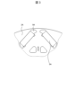
- a rotating electric machine 100 has a stator 1 and a rotor 2 .
- the rotor 2 faces the stator 1 with a predetermined air gap (air gap) therebetween.
- the rotating electrical machine 100 is, for example, a permanent magnet type rotating electrical machine used for driving a vehicle.
- the rotor 2 includes a pair of magnets 5 arranged in a V shape and a rotor core 2a formed with magnet holes 5a into which the magnets 5 are inserted.
- a magnetic gap 9 is formed radially outward.
- the magnetic gap 9 is a gap for reducing the leakage magnetic flux of the magnet 5, and is the outermost corner located radially outward among the corners between the outermost diameter portion of the rotor core 2a and the magnet 5. 5b.
- the portion near the magnetic pole center 4 of the rotor 2 is defined as the first outermost diameter portion 9a. Further, in the outermost diameter portion of the magnetic air gap 9, a portion near the magnetic pole boundary 3 of the rotor 2 is defined as a second outermost diameter portion 9b.
- another magnet 5 is formed on the rotor core 2a with the magnetic pole center 4 interposed therebetween, and such a pair of magnets 5 form one magnetic pole.
- N poles and S poles are arranged alternately.
- the magnetic pole center 4 and the magnetic pole boundary 3 are respectively the d-axis, which is the center of the N and S poles and the direction of the magnetic flux created by the magnetic poles, and the boundary between the N and S poles. is the q-axis, which is electrically and magnetically orthogonal to each other.
- a protrusion is formed on the side between the first outermost diameter portion 9a and the second outermost diameter portion 9b so as to protrude toward the magnet 5 radially inward (on the side of the central axis of the rotor core 2a).
- a section 8 is provided.
- the projecting portion 8 faces the main surface 6 of the magnet 5 with a predetermined gap therebetween.
- the main surface 6 is a surface that becomes the magnetic poles (N pole, S pole) of the rotor 2 .
- the magnetic air gap 9A provided by the magnets 5A inserted into the magnet holes of the rotor core 2A does not have a structure like the projecting portion 8 described above. If there were no projecting portion 8 as in the prior art, the path of the magnetic flux would be narrower overall and the magnetic flux density would be high, resulting in an increase in torque ripple although the maximum torque would increase.
- the protruding portion 8 is provided to partially expand the path of the magnetic flux in the outermost diameter portion of the rotor core 2a, thereby lowering the magnetic flux density and reducing the torque.
- Torque is increased by partially narrowing the first outermost diameter portion 9a and the second outermost diameter portion 9b, and the level of magnetic flux density at each rotational position is controlled.
- the maximum torque of the rotary electric machine 100 is increased compared to the conventional shape, and the torque ripple for each current phase is reduced.
- the predetermined air gap between the protrusion 8 and the main surface 6 of the magnet has an effect on stress. If this predetermined space is filled, the area of the protrusion 8 will increase and the weight will increase, and the maximum value of the stress in the portion that supports the protrusion 8 will increase. Moreover, if the supporting portion is made thicker to reduce the stress, the leakage magnetic flux will increase and the maximum torque will decrease. Therefore, by providing a predetermined gap between the projecting portion 8 and the main surface 6 of the magnet, it is possible to both suppress an increase in the maximum stress value and suppress a decrease in the maximum torque.
- the corner 5c closest to the magnetic pole boundary 3 among the corners of the magnet 5 is in contact with the rotor core 2a in order to enhance the fixing property of the magnet 5 inserted in the magnet hole 5a.
- FIG. 4(a) shows the difference in torque ripple between the configuration of the prior art (see FIG. 3) and the configuration of the present invention (see FIG. 2).
- the amount of torque fluctuation (torque ripple) of the rotating electric machine was large.
- the torque ripple is reduced as compared with the prior art indicated by the dotted line.
- FIG. 4(b) compares changes in torque ripple for each time order between the configuration of the prior art and the configuration of the present invention.
- torque ripple occurs in harmonic components that are multiples of 6 with respect to the fundamental wave, but in the present invention, the torque ripple at the 12th time order can be reduced by 60% compared to the configuration of the prior art. rice field.
- first outermost diameter portion 9a and the second outermost diameter portion 9b shown in FIG. Higher density and more torque.
- the first outermost diameter portion 9a and the second outermost diameter portion 9b are formed so that the distance 10 and the distance 11 from the outer peripheral surface of the rotor core 2a to the magnetic air gap 9 are different.
- the rotor 2 of the rotary electric machine 100 includes a pair of magnets 5 arranged in a V shape and a rotor core 2a formed with magnet holes 5a into which the magnets 5 are inserted.
- the rotor core 2a has a magnetic air gap 9 on the radially outer side with the outermost radial corner 5b of the corners of the magnet 5, which is located on the radially outermost side.
- the projecting portion 8 faces the main surface 6 of the magnet 5 .
- the projecting portion 8 faces the main surface 6 of the magnet 5 with a predetermined gap therebetween. By doing so, the stress on the rotor 2 can be reduced.
- the distance between the outer peripheral surface of the rotor 2 and the first outermost diameter portion 9a is longer than the distance between the outer peripheral surface of the rotor 2 and the second outermost diameter portion 9b.
- the corner 5c closest to the magnetic pole boundary 4 contacts the rotor core 2a. By doing so, the magnet 5 is more fixed to the rotor core 2a.
- the rotary electric machine 100 includes the stator 1 facing the rotor 2 shown in the embodiment of the present invention with a predetermined air gap therebetween. By doing so, it is possible to realize the rotary electric machine 100 that achieves both an increase in maximum torque and a reduction in stress, and further reduces torque ripple.
- the present invention is not limited to the above embodiments, and various modifications and other configurations can be combined without departing from the scope of the invention. Moreover, the present invention is not limited to those having all the configurations described in the above embodiments, and includes those having some of the configurations omitted.
Landscapes
- Engineering & Computer Science (AREA)
- Power Engineering (AREA)
- Permanent Field Magnets Of Synchronous Machinery (AREA)
Priority Applications (4)
| Application Number | Priority Date | Filing Date | Title |
|---|---|---|---|
| CN202180104200.XA CN118251824A (zh) | 2021-11-16 | 2021-11-16 | 旋转电机的转子 |
| PCT/JP2021/042124 WO2023089670A1 (ja) | 2021-11-16 | 2021-11-16 | 回転電機の回転子 |
| US18/710,078 US20250023406A1 (en) | 2021-11-16 | 2021-11-16 | Rotor of rotating electric machine |
| JP2023561961A JP7651724B2 (ja) | 2021-11-16 | 2021-11-16 | 回転電機の回転子 |
Applications Claiming Priority (1)
| Application Number | Priority Date | Filing Date | Title |
|---|---|---|---|
| PCT/JP2021/042124 WO2023089670A1 (ja) | 2021-11-16 | 2021-11-16 | 回転電機の回転子 |
Publications (1)
| Publication Number | Publication Date |
|---|---|
| WO2023089670A1 true WO2023089670A1 (ja) | 2023-05-25 |
Family
ID=86396370
Family Applications (1)
| Application Number | Title | Priority Date | Filing Date |
|---|---|---|---|
| PCT/JP2021/042124 Ceased WO2023089670A1 (ja) | 2021-11-16 | 2021-11-16 | 回転電機の回転子 |
Country Status (4)
| Country | Link |
|---|---|
| US (1) | US20250023406A1 (https=) |
| JP (1) | JP7651724B2 (https=) |
| CN (1) | CN118251824A (https=) |
| WO (1) | WO2023089670A1 (https=) |
Citations (3)
| Publication number | Priority date | Publication date | Assignee | Title |
|---|---|---|---|---|
| JP2013188023A (ja) * | 2012-03-08 | 2013-09-19 | Nissan Motor Co Ltd | 永久磁石式電動機のロータ |
| JP2020120444A (ja) * | 2019-01-21 | 2020-08-06 | 本田技研工業株式会社 | 回転電機のロータおよび回転電機 |
| WO2021214824A1 (ja) * | 2020-04-20 | 2021-10-28 | 三菱電機株式会社 | ロータ、モータ、圧縮機、空気調和装置およびロータの製造方法 |
-
2021
- 2021-11-16 WO PCT/JP2021/042124 patent/WO2023089670A1/ja not_active Ceased
- 2021-11-16 CN CN202180104200.XA patent/CN118251824A/zh active Pending
- 2021-11-16 US US18/710,078 patent/US20250023406A1/en active Pending
- 2021-11-16 JP JP2023561961A patent/JP7651724B2/ja active Active
Patent Citations (3)
| Publication number | Priority date | Publication date | Assignee | Title |
|---|---|---|---|---|
| JP2013188023A (ja) * | 2012-03-08 | 2013-09-19 | Nissan Motor Co Ltd | 永久磁石式電動機のロータ |
| JP2020120444A (ja) * | 2019-01-21 | 2020-08-06 | 本田技研工業株式会社 | 回転電機のロータおよび回転電機 |
| WO2021214824A1 (ja) * | 2020-04-20 | 2021-10-28 | 三菱電機株式会社 | ロータ、モータ、圧縮機、空気調和装置およびロータの製造方法 |
Also Published As
| Publication number | Publication date |
|---|---|
| JP7651724B2 (ja) | 2025-03-26 |
| JPWO2023089670A1 (https=) | 2023-05-25 |
| CN118251824A (zh) | 2024-06-25 |
| US20250023406A1 (en) | 2025-01-16 |
Similar Documents
| Publication | Publication Date | Title |
|---|---|---|
| JP5935615B2 (ja) | 回転電機のロータ | |
| KR100983862B1 (ko) | 회전전기기계 | |
| US8436504B2 (en) | Stator for an electric machine | |
| JP2008104323A (ja) | 永久磁石式リラクタンス型回転電機 | |
| KR101826126B1 (ko) | 3상 전자 모터 | |
| KR20170043464A (ko) | 회전 전기 기기, 회전자 철심의 제조 방법 | |
| CN104221261A (zh) | 永磁铁马达 | |
| US20120025665A1 (en) | Single-phase brushless motor | |
| US10432043B2 (en) | Slotted rotor-bridge for electrical machines | |
| JP6507956B2 (ja) | 永久磁石式回転電機 | |
| JP2009050148A (ja) | 広範囲定出力永久磁石式モータ | |
| US20220294284A1 (en) | Electric machine stator and method for reducing torque ripple of electric machine | |
| KR101600835B1 (ko) | 매입형 영구자석 동기 전동기 및 그 회전자 | |
| CN103248153B (zh) | 旋转电机 | |
| US12027918B2 (en) | Rotor and electric motor | |
| JP2018085877A (ja) | 回転電機 | |
| JP2007060755A (ja) | 回転電機の回転子構造 | |
| JP6987318B1 (ja) | 永久磁石同期モータ | |
| JP7651724B2 (ja) | 回転電機の回転子 | |
| JP2019161828A (ja) | 回転電機 | |
| JP2022121978A (ja) | 回転電機 | |
| JP2019017208A (ja) | 回転子及び永久磁石式回転電機 | |
| JP2024007285A (ja) | 埋込磁石型回転子および回転電機 | |
| JP2017131001A (ja) | 回転電機 | |
| WO2019234866A1 (ja) | ロータ及びモータ |
Legal Events
| Date | Code | Title | Description |
|---|---|---|---|
| 121 | Ep: the epo has been informed by wipo that ep was designated in this application |
Ref document number: 21964686 Country of ref document: EP Kind code of ref document: A1 |
|
| ENP | Entry into the national phase |
Ref document number: 2023561961 Country of ref document: JP Kind code of ref document: A |
|
| WWE | Wipo information: entry into national phase |
Ref document number: 202180104200.X Country of ref document: CN |
|
| WWE | Wipo information: entry into national phase |
Ref document number: 18710078 Country of ref document: US |
|
| 122 | Ep: pct application non-entry in european phase |
Ref document number: 21964686 Country of ref document: EP Kind code of ref document: A1 |