WO2023085254A1 - 車両用アンテナ装置 - Google Patents
車両用アンテナ装置 Download PDFInfo
- Publication number
- WO2023085254A1 WO2023085254A1 PCT/JP2022/041507 JP2022041507W WO2023085254A1 WO 2023085254 A1 WO2023085254 A1 WO 2023085254A1 JP 2022041507 W JP2022041507 W JP 2022041507W WO 2023085254 A1 WO2023085254 A1 WO 2023085254A1
- Authority
- WO
- WIPO (PCT)
- Prior art keywords
- conductive film
- antenna
- main surface
- vehicle
- film
- Prior art date
- Legal status (The legal status is an assumption and is not a legal conclusion. Google has not performed a legal analysis and makes no representation as to the accuracy of the status listed.)
- Ceased
Links
Images


Classifications
-
- H—ELECTRICITY
- H01—ELECTRIC ELEMENTS
- H01Q—ANTENNAS, i.e. RADIO AERIALS
- H01Q9/00—Electrically-short antennas having dimensions not more than twice the operating wavelength and consisting of conductive active radiating elements
- H01Q9/04—Resonant antennas
- H01Q9/0485—Dielectric resonator antennas
-
- H—ELECTRICITY
- H01—ELECTRIC ELEMENTS
- H01Q—ANTENNAS, i.e. RADIO AERIALS
- H01Q1/00—Details of, or arrangements associated with, antennas
- H01Q1/27—Adaptation for use in or on movable bodies
- H01Q1/32—Adaptation for use in or on road or rail vehicles
- H01Q1/325—Adaptation for use in or on road or rail vehicles characterised by the location of the antenna on the vehicle
- H01Q1/3275—Adaptation for use in or on road or rail vehicles characterised by the location of the antenna on the vehicle mounted on a horizontal surface of the vehicle, e.g. on roof, hood, trunk
-
- B—PERFORMING OPERATIONS; TRANSPORTING
- B60—VEHICLES IN GENERAL
- B60J—WINDOWS, WINDSCREENS, NON-FIXED ROOFS, DOORS, OR SIMILAR DEVICES FOR VEHICLES; REMOVABLE EXTERNAL PROTECTIVE COVERINGS SPECIALLY ADAPTED FOR VEHICLES
- B60J1/00—Windows; Windscreens; Accessories therefor
-
- H—ELECTRICITY
- H01—ELECTRIC ELEMENTS
- H01P—WAVEGUIDES; RESONATORS, LINES, OR OTHER DEVICES OF THE WAVEGUIDE TYPE
- H01P5/00—Coupling devices of the waveguide type
- H01P5/02—Coupling devices of the waveguide type with invariable factor of coupling
-
- H—ELECTRICITY
- H01—ELECTRIC ELEMENTS
- H01Q—ANTENNAS, i.e. RADIO AERIALS
- H01Q1/00—Details of, or arrangements associated with, antennas
- H01Q1/12—Supports; Mounting means
- H01Q1/1271—Supports; Mounting means for mounting on windscreens
-
- H—ELECTRICITY
- H01—ELECTRIC ELEMENTS
- H01Q—ANTENNAS, i.e. RADIO AERIALS
- H01Q21/00—Antenna arrays or systems
- H01Q21/28—Combinations of substantially independent non-interacting antenna units or systems
-
- H—ELECTRICITY
- H01—ELECTRIC ELEMENTS
- H01Q—ANTENNAS, i.e. RADIO AERIALS
- H01Q9/00—Electrically-short antennas having dimensions not more than twice the operating wavelength and consisting of conductive active radiating elements
- H01Q9/04—Resonant antennas
- H01Q9/0407—Substantially flat resonant element parallel to ground plane, e.g. patch antenna
-
- H—ELECTRICITY
- H01—ELECTRIC ELEMENTS
- H01Q—ANTENNAS, i.e. RADIO AERIALS
- H01Q1/00—Details of, or arrangements associated with, antennas
- H01Q1/27—Adaptation for use in or on movable bodies
- H01Q1/32—Adaptation for use in or on road or rail vehicles
Definitions
- the present invention relates to a vehicle antenna device.
- This application claims priority based on Japanese Patent Application No. 2021-184698 filed in Japan on November 12, 2021, the content of which is incorporated herein.
- conductive films such as Low-E and heat ray reflective films, and light control films that can electrically (actively) change the visible light transmittance. or provide thermal/optical added value.
- a conductive film when a conductive film is coated on a dielectric such as glass, it can be used as a glass antenna that receives a predetermined broadcast wave by arranging a wire conductor pattern on the vehicle window glass like a conventional vehicle window glass. desired antenna gain is not obtained.
- Japanese Patent Laid-Open No. 2002-200003 is known as a technique that uses a conductive film coating as an antenna.
- an antenna element including a conductive film that is heated by applying a voltage between a pair of bus bars is used for terrestrial digital television broadcast waves, DAB (Digital Audio Broadcast) broadcast waves, and FM broadcast waves. It is described that it functions as an antenna that can receive Further, in Patent Document 1, by providing a grid portion of a region in which the conductor portion of the conductive film is removed and the resistance thereof is increased, the antenna can function as an antenna capable of receiving AM broadcast waves.
- the present invention provides a vehicle antenna device that can easily receive AM broadcast waves using a conductive film in a vehicle window glass using a conductive film.
- a vehicle antenna device includes a dielectric substrate having a first main surface and a second main surface, and a dielectric substrate provided on the second main surface side, the area of the dielectric substrate in plan view being a conductive film that is 0.025 m 2 or more.
- the conductive film has a sheet resistance value of 1.5 ⁇ 10 3 ⁇ / ⁇ or less, and can receive AM broadcast waves from a feeding point electrically connected to the conductive film.
- the feeding point is arranged in a central portion of the conductive film, which is separated from an edge of the dielectric substrate by 150 mm or more in plan view of the dielectric substrate. good too.
- the outer edge of the conductive film may be substantially quadrangular in plan view of the dielectric substrate.
- the feeding point electrically connected to the conductive film is a first feeding point, provided on the first main surface side, and having VHF band and UHF band an antenna for receiving radio waves of at least one of the frequencies of; an antenna electrode arranged inside an outer edge of a pore region inside the conductive film in a plan view of the dielectric substrate; and connected to the antenna.
- the antenna conductor may be electrically connected to the antenna electrode, and may be capable of receiving radio waves of at least one of VHF band and UHF band frequencies by a signal received using the antenna electrode as a second feeding point.
- the antenna conductor and the antenna electrode may be electrically connected by capacitive coupling.
- the antenna conductor and the antenna electrode may be directly connected by a connection conductor arranged in a through hole of the dielectric substrate.
- the dielectric substrate is a first dielectric substrate, and the second main surface side of the first dielectric substrate has a dielectric parallel to the second main surface. and an intermediate film disposed between the first dielectric substrate and the second dielectric substrate.
- the second dielectric substrate has a third main surface on the side of the first dielectric substrate and a fourth main surface on the side opposite to the third main surface, and the conductive film has the third main surface.
- the antenna electrode may be arranged between the first dielectric substrate and the second dielectric substrate, and the antenna electrode may be arranged on the fourth main surface side.
- the conductive film may be arranged in contact with the second main surface.
- the intermediate film includes a first intermediate film and a second intermediate film
- the conductive film includes the first intermediate film and the second intermediate film. may be sandwiched between
- the conductive film may be a light control film containing a conductor.
- the conductive film may be arranged in contact with the third main surface or the fourth main surface.
- the intermediate film includes a first intermediate film and a second intermediate film
- the conductive film includes a first conductive film and a second conductive film.
- the first conductive film and the second conductive film are located on the second main surface, between the first intermediate film and the second intermediate film, and on the third main surface and a position on the fourth main surface, and are arranged in order from the one closest to the first dielectric substrate, and the second conductive film is located on the plane of the first dielectric substrate.
- it may have a second pore region arranged so as to overlap with the first pore region which is the pore region of the first conductive film.
- the first conductive film is arranged in contact with the second main surface, and the second conductive film is formed of the first intermediate film and the second intermediate film. may be sandwiched between
- the first conductive film may be a conductor for reflecting heat rays
- the second conductive film may be a light control film including a conductor
- the conductive film includes a third conductive film disposed in contact with the fourth main surface, and the third conductive film is for a low emissivity film. conductor.
- the first conductive film is sandwiched between the first intermediate film and the second intermediate film, and the second conductive film It may be placed in contact with the surface.
- the first conductive film may be a light control film containing a conductor
- the second conductive film may be a conductor for a low emissivity film.
- the antenna is capable of receiving the frequency of FM broadcast waves, includes an AM amplifier and an FM amplifier, and the signal in the frequency band of AM broadcast waves is the first A signal in a frequency band of an FM broadcast wave may be input from a feeding point to the AM amplifier and input to the FM amplifier from the second feeding point.
- the filter may be a capacitor, and the capacitor may have a capacity of 5 pF to 150 pF.
- the antenna may be surrounded by a cover member projecting outward from the first main surface side of the dielectric substrate.
- the dielectric substrate may be a glass substrate.
- the dielectric substrate may be attached to the roof of the vehicle in parallel with the horizontal plane of the vehicle.
- the vehicle antenna device can easily receive AM broadcast waves using the conductive film in the vehicle window glass using the conductive film.
- BRIEF DESCRIPTION OF THE DRAWINGS It is a perspective view which shows typically an example of the vehicle antenna apparatus of 1st Embodiment. BRIEF DESCRIPTION OF THE DRAWINGS It is sectional drawing which shows an example of the vehicle antenna apparatus of 1st Embodiment. BRIEF DESCRIPTION OF THE DRAWINGS It is a block diagram by the planar view which shows an example of the vehicle glass of 1st Embodiment. BRIEF DESCRIPTION OF THE DRAWINGS It is a block diagram by the planar view which shows an example of the vehicle glass of 1st Embodiment.
- FIG. 12 is a cross-sectional view showing an example of a vehicle antenna device according to an eighth embodiment
- the member A is present, but also the case where the member A is arranged so as to be separated from the main surface. Moreover, when the main surface and the member A are spaced apart, there may or may not be an intervening material between the main surface and the member A.
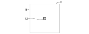
- FIG. 1 is a perspective view schematically showing an example of the vehicle antenna device 1 of the first embodiment.
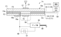
- FIG. 2 is a cross-sectional view showing an example of the vehicle antenna device 1 of this embodiment.
- the cross-sectional view shown in FIG. 2 is a cross-sectional view taken along line AB of area AR1 in FIG.
- the vehicle antenna device 1 uses vehicle glass 10 .
- a vehicle antenna device 1 includes a vehicle glass 10 , an antenna section 20 , an amplifier section 30 and a filter 40 .
- Filter 40 may be a high-pass filter or a band-stop filter. Hereinafter, unless otherwise specified, the high-pass filter 40 will be described.
- the vehicle glass 10 is, for example, roof glass attached to the roof of the vehicle.
- the vehicle glass 10 is attached to the roof of the vehicle parallel (including substantially parallel) to the horizontal plane of the vehicle.
- a configuration example of the vehicle glass 10 will be described with reference to FIG. 2 .
- the vehicle glass 10 is, for example, a single plate glass.
- the vehicle glass 10 includes a glass substrate 11 , an antenna conductor 12 , a conductive film 13 , an antenna electrode 15 , a feeding point 16 and a shielding layer 17 .
- the shape of the vehicle glass 10 may be a curved shape or a planar shape (non-curved shape). Further, the vehicle glass 10 may have, for example, a single-curved shape curved in one of the vertical and horizontal directions (with respect to one side of the frame) when mounted on a vehicle.
- the vehicle glass 10 may have a compound curved shape that is curved both vertically and horizontally. Note that the single-curved shape may be a shape curved in only one arbitrary direction.
- a compound curved shape may be a shape curved in any two or more different directions.
- the minimum value of the radius of curvature of the vehicle glass 10 is preferably 500 mm or more and 100000 mm or less.
- the glass substrate 11 is an example of a dielectric substrate and has a first main surface F1 and a second main surface F2.
- the main surface of the glass substrate 11 on the outside of the vehicle is the first main surface F1.
- the main surface opposite to the first main surface F1 side is the second main surface F2.
- the antenna conductor 12 is an electrode connected to the antenna 21, and is arranged on the first main surface F1 side.
- the antenna conductor 12 is formed, for example, on the first main surface F1 side of the glass substrate 11 so as to be in contact with the glass substrate 11 (on the glass substrate 11).
- FIGS. 3A to 3C are plan views of the antenna conductor 12 viewed from outside the vehicle.
- FIG. 3A to 3C are configuration diagrams in plan view showing an example of the vehicle glass 10 of the present embodiment.
- FIG. 3A is a plan view of the vehicle glass 10 as viewed from the outside of the vehicle (first main surface F1).
- the antenna conductor 12 is arranged as a square electrode in the central portion of the first main surface F1 of the glass substrate 11, as shown in FIG. 3A. That is, the antenna conductor 12 is formed in a rectangular shape (including a substantially rectangular shape) in a plan view of the glass substrate 11 .
- the conductive film 13 includes, for example, a conductive film for heat reflection (heat ray reflective film), a conductive film for low radiation (Low-E (Low Emissivity) coating, which coats the vehicle glass 10).
- a typical example of the heat ray reflective film is a metal film, and examples of the metal film include silver (Ag).
- a low-emissivity film such as a Low-E film secures heat insulation by suppressing heat transfer by radiation.
- the Low-E film may be, for example, a laminated film including a transparent dielectric film, an infrared reflective film, and a transparent dielectric film in this order.
- Typical transparent dielectric films are metal oxides and metal nitrides, and typical metal oxides are zinc oxide and tin oxide.
- the conductive film 13 is provided on the second main surface F2 side with respect to the glass substrate 11 .
- the area of the glass substrate 11 in plan view is preferably 0.025 m 2 or more, more preferably 0.050 m 2 or more, and more preferably 0.100 m 2 or more. More preferably, it is 0.250 m 2 or more, and particularly preferably 0.500 m 2 .
- the outer edge of the conductive film 13 is, for example, substantially rectangular in plan view of the glass substrate 11 in accordance with the shape of the glass substrate 11 .
- the conductive film 13 functions as an AM antenna and as an antenna ground for the antenna 21 .
- the conductive film 13 preferably has a sheet resistance value of 1.5 ⁇ 10 3 ⁇ / ⁇ (ohm/square) or less.
- the sheet resistance value of the conductive film 13 is more preferably 1.0 ⁇ 10 3 ⁇ / ⁇ or less, further preferably 500 ⁇ / ⁇ or less, particularly preferably 300 ⁇ / ⁇ or less, and most preferably 200 ⁇ / ⁇ or less.
- the conductive film 13 has a void region VA inside when the glass substrate 11 is viewed from above.
- the void area VA is arranged so as not to overlap the antenna conductor 12 and the antenna electrode 15 in the thickness direction of the vehicle glass 10 . Further, as shown in FIG. 3B, the void regions VA are arranged as square void regions in plan view of the glass substrate 11 . That is, the void area VA is formed in a rectangular shape (including a substantially rectangular shape) in a plan view of the glass substrate 11 .
- the antenna electrode 15 is arranged on the second main surface F2 side inside the outer edge of the hole area VA in plan view of the glass substrate 11, and is electrically connected to the antenna conductor 12. be done.
- the antenna electrode 15 is arranged, for example, in contact with the second main surface F2 of the glass substrate 11 .
- the antenna electrode 15 and the antenna conductor 12 sandwich the glass substrate 11 .
- the antenna electrode 15 is formed on the opposite side of the glass substrate 11 from the antenna conductor 12 .
- the antenna conductor 12 and the antenna electrode 15 are arranged so as to be capacitively coupled.
- the distance between the antenna conductor 12 and the antenna electrode 15 is approximately 5 mm.
- the distance of the dielectric between the conductors may be less than 30 mm, preferably 20 mm or less, more preferably 10 mm or less.
- the thickness of the vehicle glass 10 is typically about 2 mm to 5 mm including the laminated glass described later. is. Thus, if the thickness of the vehicle glass 10 is less than 30 mm, capacitive coupling between the antenna conductor 12 and the antenna electrode 15 becomes possible, and the circuit can be configured such that the signal received by the antenna 21 is amplified by the amplifier section 30. .
- the shielding layer 17 is arranged on the side of the conductive film 13 opposite to the glass substrate 11 .
- the shielding layer 17 has a pore region whose outer edge is arranged outside the outer edge of the pore region VA of the conductive film 13 .
- the shielding layer 17 is arranged on the conductive film 13 so that the feeding point 16 is exposed.
- the shielding layer 17 shields visible light.
- the shielding layer 17 is an opaque colored ceramic layer.
- the color of the shielding layer 17 is arbitrarily selected.
- the color of the shielding layer 17 is preferably a dark color such as black, brown, gray, dark blue, or white, and more preferably black.
- the hole regions of the shielding layer 17 are formed in a rectangular shape (including a substantially rectangular shape) in a plan view of the glass substrate 11, similarly to the hole regions VA.
- the arrangement of the shielding layer 17 is arbitrarily selected. Also, the shielding layer 17 may be omitted. Furthermore, when the shielding layer 17 is arranged, the shielding layer 17 may be formed in a state in which the shielding layer 17 does not have a void region, that is, the shielding layer 17 may be formed in a so-called “solid shape”. In that case, the shielding layer 17 may be formed (solidly) on the second main surface F2 of the glass substrate 11 . The reason for this is that since the thickness of the shielding layer 17 is about 5 ⁇ m to 25 ⁇ m, even if a structure in which the shielding layer 17 is interposed is adopted, the change in the coupling capacitance between the antenna conductor 12 and the antenna electrode 15 is small.
- the vehicle antenna device 1 is described as having the shielding layer 17 having a hole region.
- the feeding point 16 is an exposed portion where the conductive film 13 is exposed.
- the feeding point 16 is electrically connected to the conductive film 13 .
- the vehicle antenna device 1 can receive AM broadcast waves from the feeding point 16 .
- the feeding point 16 is arranged in the central portion of the conductive film 13 150 mm or more inwardly away from the edge of the glass substrate 11 in plan view of the glass substrate 11 . Note that even if the shielding layer 17 is formed in a solid shape with no void regions as described above, the feeding points 16 may be electrically connected by capacitive coupling.
- the feeding point 16 is preferably spaced inward from the edge of the glass substrate 11 by 200 mm or more, and more preferably spaced inward from the edge of the glass substrate 11 by 300 mm or more.
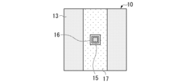
- FIG. 3C is a plan view of the vehicle glass 10 as seen from the inside of the vehicle (the side of the second main surface F2).
- the antenna electrode 15 is formed in a rectangular shape (including a substantially rectangular shape) in plan view of the glass substrate 11 .
- the antenna electrode 15 is arranged on the second main surface F2 side and formed in a square shape.
- the feeding point 16 is formed in a square loop shape when the glass substrate 11 is viewed from above. That is, the shape of each of the outer edge and the inner edge of the feeding point 16 is square. It should be noted that the loop shape may be a closed loop that is connected over one round, or a shape having one or more cutouts. When the feeding point 16 has a notch, the length of the notch may be, for example, 40 or less, 30 or less, or 20 or less, when the length of one round in the closed loop is normalized to "100". good. Moreover, the length of the notch portion based on the above standardization may be, for example, 1 or more, 2 or more, or 5 or more.
- the feeding point 16 is an example of a first feeding point for receiving AM broadcast waves
- the antenna electrode 15 is an example of a second feeding point for receiving FM broadcast waves.
- the antenna section 20 includes an antenna 21 and an antenna cover 22 .
- the antenna 21 is, for example, an antenna for receiving the frequency band of FM broadcast waves, an antenna for receiving the frequency band of DAB (Digital Audio Broadcast) broadcast waves, and an antenna for receiving the frequency band of terrestrial digital television broadcast waves.
- GNSS Global Navigation Satellite System
- SDARS Setellite Digital Audio Radio Service
- the frequency band of FM broadcast waves (hereinafter referred to as “FM band”) is from 76 MHz (megahertz) to 108 MHz
- the frequency band of DAB Band III broadcast waves (hereinafter referred to as “DAB band”) is from 174 MHz It is 240MHz.
- the frequency band of terrestrial digital television broadcasting waves (hereinafter referred to as “DTV band”) is 470 MHz to 710 MHz.
- the antenna 21 may be capable of receiving a plurality of frequency bands among the FM broadcast wave frequency band, the DAB broadcast wave frequency band, the terrestrial digital television broadcast wave frequency band, the GNSS frequency band, and the SDARS frequency band.
- the antenna 21 is arranged outside the vehicle glass 10 and connected to the antenna conductor 12 .
- the antenna cover 22 (cover member) is a projecting cover grounded on the roof of the vehicle.
- the antenna cover 22 houses the antenna 21 inside.
- the antenna cover 22 is, for example, a shark fin antenna cover.
- the amplifier unit 30 amplifies the received signal of AM broadcast waves received by the conductive film 13 as an AM antenna and the received signal of FM broadcast waves received by the antenna 21, and outputs the amplified signals to, for example, a receiver.
- An input terminal for AM broadcast waves of amplifier section 30 is connected to feeding point 16 , and an input terminal for FM broadcast waves is connected to antenna electrode 15 .
- the output of the amplifier section 30 is supplied to a receiver via a transmission line such as a coaxial cable CB. Details of the amplifier unit 30 will be described later.
- the high-pass filter 40 is arranged between the conductive film 13 and the ground, which is the vehicle body (ground conductor). Between the conductive film 13 and the vehicle body, the high-pass filter 40 passes signals in at least one of the VHF band and UHF band frequencies, and cuts off signals in the AM broadcast wave frequency band. That is, the high-pass filter 40 grounds the conductive film 13 with respect to the vehicle body in the VHF band or higher, and makes the conductive film 13 electrically floating (high impedance state) in the AM band.
- High-pass filter 40 is, for example, capacitor C1.
- the capacitance of the capacitor C1 is preferably 5 pF to 150 pF, more preferably 5 pF to 100 pF.
- the capacitor C1 is a capacitor element connected between the conductive film 13 and the vehicle body. Note that the capacitor C ⁇ b>1 may be located inside the amplifier section 30 .
- FIG. 4 is a diagram showing an equivalent circuit of the vehicle antenna device 1 of this embodiment.
- the amplifier section 30 includes an AM amplifier 31 , an FM amplifier 32 and a signal mixer 33 .
- the conductive film 13 functions as an AM antenna and as an antenna ground for the antenna 21 .
- the conductive film 13 is connected to the ground of the amplifier section 30 and the signal ground of the output signal via the capacitor C1 in at least one of the VHF band and the UHF band.
- the ground of the amplifier section 30 and the signal ground of the output signal are connected to the vehicle body BD.
- the capacitance between the vehicle body BD and the conductive film 13 is assumed to be antenna capacitance (C3).
- the conductive film 13 is connected to the input signal line of the AM amplifier 31 through the feeding point 16 .
- a reception signal received by the conductive film 13 as an AM antenna is inputted to the AM amplifier 31 as an input signal. Further, the conductive film 13 is electrically cut off from the ground of the amplifier section 30 and the signal ground of the output signal by the capacitor C1 in the AM broadcast wave frequency band.
- Capacitor C2 is an electrostatic capacitance formed by antenna conductor 12 to which antenna 21 is connected and antenna electrode 15 .
- the capacitor C2 electrically connects the antenna conductor 12 and the antenna electrode 15 by capacitive coupling.
- a reception signal received by the antenna 21 is input to the FM amplifier 32 as an input signal by capacitive coupling of the capacitor C2.
- the AM amplifier 31 amplifies the reception signal of the AM broadcast wave received by the conductive film 13 and outputs the amplified signal to the signal mixer 33 .
- the FM amplifier 32 amplifies the received signal of the VHF band or higher frequency (for example, FM broadcast wave) received by the antenna 21 and outputs the amplified signal to the signal mixer 33 .
- the signal of the VHF band or higher frequency is, for example, one or more signals of at least one of the VHF band frequency and the UHF band frequency.
- the signal mixer 33 mixes the received signal of the AM broadcast wave output by the AM amplifier 31 and the received signal of the VHF band or higher frequency (for example, FM broadcast wave) output by the FM amplifier 32 into a coaxial signal. Output to a receiver (not shown) via cable CB.
- FIG. 5 is a diagram showing the antenna characteristics of the vehicle antenna device 1 of this embodiment for AM broadcast waves.
- the graph shows measured values of antenna characteristics in the frequency band of AM broadcast waves when the conductive film 13 is a conductor of 950 mm ⁇ 1150 mm.
- a solid line W1 indicates antenna sensitivity with an amplifier (AM amplifier 31), and a solid line W2 indicates antenna sensitivity without an amplifier.
- a capacitor C1 with a capacity of 51 pF is connected.
- the conductive film 13 functions as an AM antenna for receiving AM broadcast wave signals.
- the vehicle antenna device 1 can obtain a sufficient antenna sensitivity of about 60 dB in the AM broadcast wave frequency band.
- FIG. 6 is a diagram showing the antenna characteristics of the FM broadcast wave of the vehicle antenna device 1 of this embodiment.
- FIG. 6 shows measured values of antenna characteristics in the frequency band of FM broadcast waves when the conductive film 13 is a conductor of 950 mm ⁇ 1150 mm (solid line W3).
- the conductive film 13 functions as an antenna ground and connects a capacitor C1 with a ground capacitance of 51 pF.
- the vehicle antenna device 1 can obtain a sufficient antenna sensitivity of 50 dB or more in the frequency band of FM broadcast waves.
- FIG. 7 is a diagram showing the relationship between the grounding capacity and the sheet resistance of the vehicle antenna device 1 of this embodiment.
- FIG. 7 shows simulation values when the size of the conductive film 13 is 950 mm ⁇ 1150 mm, the antenna capacitance (C3) is 170 pF, the input capacitance of the AM amplifier 31 is 50 pF, and the frequency is 1000 kHz.
- the horizontal axis of the graph indicates the capacitance (ground capacitance) of the capacitor C1.
- the vertical axis of the graph indicates the sheet resistance value of the conductive film 13 .
- a dashed line W4 indicates a sheet resistance value with respect to the capacitance of the capacitor C1, which is ⁇ 3 dB lower than the signal attenuation amount when the sheet resistance of the conductive film 13 is 0 ⁇ / ⁇ . That is, the dashed line W4 indicates the maximum sheet resistance value within -3 dB.
- a range R1 indicates a sheet resistance range in which the attenuation amount is within -3 dB.
- a range RC1 indicates a range of capacitance (ground capacitance) of the capacitor C1 from 5 pF to 150 pF. As shown in FIG. 7, by setting the sheet resistance value to 1500 ⁇ / ⁇ or less in the capacitance range RC1 of the capacitor C1, sufficient signal sensitivity for AM broadcast waves can be ensured.
- FIG. 8 is a diagram showing the relationship between the grounding capacity and the antenna capacity of the vehicle antenna device 1 of this embodiment.
- FIG. 8 shows simulation values when the size of the conductive film 13 is 950 mm ⁇ 1150 mm, the sheet resistance is 150 ⁇ / ⁇ , the input capacitance of the AM amplifier 31 is 50 pF, and the frequency is 1000 kHz.
- the horizontal axis of the graph indicates the capacitance (grounded capacitance) of the capacitor C1
- the vertical axis indicates the antenna capacitance (C3).
- a dashed line W5 indicates the antenna capacitance (C3) with respect to the capacitance of the capacitor C1 at which the attenuation of the received signal is -10 dB. That is, the dashed line W5 indicates the Min value (minimum value) at which the amount of attenuation of the received signal is -10 dB or more.
- a range R2 indicates a range of antenna capacity (C3) in which the attenuation amount is -10 dB or more.
- a range RC1 indicates a range of capacitance (ground capacitance) of the capacitor C1 from 5 pF to 150 pF. As shown in FIG. 8, by setting the antenna capacitance (C3) to 100 pF or more in the range RC1 of the capacitance of the capacitor C1, the signal sensitivity of the AM broadcast wave can be ensured.
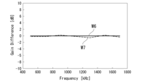
- FIG. 9 is a diagram showing an example of antenna characteristics when a conductive film 13 having a relatively high resistance is used in the vehicle antenna device 1 of this embodiment.
- the horizontal axis of the graph indicates reception frequency
- the vertical axis indicates reception voltage (dB).
- a solid line W6 indicates the antenna sensitivity when the conductive film 13 is a copper tape with a size of 50 mm ⁇ 500 mm
- a dashed line W7 indicates the conductive film 13 with a size of 50 mm ⁇ 500 mm and a sheet resistance of 150 ⁇ / ⁇ .
- Antenna sensitivity for film is shown.
- a solid line W6 and a dashed line W7 are measured values.
- solid line W6 with low resistance (for example, 0.1 ⁇ / ⁇ or less) and the conductive film with high resistance (broken line W7).
- 60 dB or more can be secured in the frequency band of broadcast waves. That is, a relatively high-resistance conductive film 13 having a sheet resistance of about 150 ⁇ / ⁇ , such as a Low-E coat (conductive film for low radiation), can be used as an AM antenna.
- the Low-E coating may be applied not only to vehicle window glass attached to the roof, but also to side glass and rear glass.
- the vehicle antenna device 1 of this embodiment includes the glass substrate 11 (dielectric substrate) and the conductive film 13 .
- the glass substrate 11 has a first main surface F1 and a second main surface F2.
- the conductive film 13 is provided on the second main surface F2 side, and has an area of 0.025 m 2 or more in plan view of the glass substrate 11 .
- the conductive film 13 has a sheet resistance value of 1.5 ⁇ 10 3 ⁇ / ⁇ or less.
- the sheet resistance value of the conductive film 13 is more preferably 1.0 ⁇ 10 3 ⁇ / ⁇ or less, further preferably 500 ⁇ / ⁇ or less, and particularly preferably 200 ⁇ / ⁇ or less.
- the vehicle antenna device 1 can receive AM broadcast waves from a feeding point 16 electrically connected to the conductive film 13 .
- the vehicle antenna device 1 of the present embodiment for example, a coating such as a conductive film for heat ray reflection (heat ray reflective film), a conductive film for low radiation (Low-E coat), etc., can be applied to AM broadcast waves.
- a coating such as a conductive film for heat ray reflection (heat ray reflective film), a conductive film for low radiation (Low-E coat), etc.
- the vehicle antenna device 1 of the present embodiment can easily receive AM broadcast waves using the conductive film 13 in the vehicle glass 10 (vehicle window glass) using the conductive film 13 .
- the vehicle antenna device 1 of this embodiment can obtain a sufficient antenna gain in the frequency band of AM broadcast waves.
- the feeding point 16 is arranged in the central portion of the conductive film 13 away from the edge of the glass substrate 11 by 150 mm or more in plan view of the glass substrate 11 . Further, the outer edge of the conductive film 13 is substantially quadrangular in plan view of the glass substrate 11 . As a result, the vehicle antenna device 1 of the present embodiment can easily receive AM broadcast waves using the conductive film 13 in, for example, a roof antenna.
- the feeding point 16 electrically connected to the conductive film 13 is the first feeding point.
- the vehicle antenna device 1 includes an antenna 21 , an antenna electrode 15 , an antenna conductor 12 and a high-pass filter 40 .
- the antenna 21 is provided on the first main surface F1 side, and receives radio waves of at least one of frequencies in the VHF band and the UHF band.
- the antenna electrode 15 is arranged inside the outer edge of the void area VA inside the conductive film 13 in plan view of the glass substrate 11 .
- the antenna conductor 12 is connected to the antenna 21 and arranged on the first main surface F1 side.
- the high-pass filter 40 passes signals in at least one of the VHF and UHF frequency bands, and cuts off signals in the AM broadcast frequency band.
- Antenna conductor 12 is electrically connected to antenna electrode 15 .
- the vehicle antenna device 1 can receive radio waves of at least one of frequencies in the VHF band and the UHF band by a signal received using the antenna electrode 15 as a second feeding point.
- the conductive film 13 can be used both as a receiving antenna (AM antenna) for the frequency band of AM broadcast waves and as an antenna ground for the antenna 21.
- AM antenna receiving antenna
- a large area can be secured. Therefore, the vehicle antenna device 1 of the present embodiment can easily receive AM broadcast waves by using the conductive film 13, and can obtain a sufficient antenna gain for at least one of the radio waves in the VHF band and the UHF band. be done. Moreover, sufficient antenna gain can be obtained without mechanical processing such as drilling of the glass substrate 11 for the antenna 21 .
- the antenna conductor 12 and the antenna electrode 15 are electrically connected by capacitive coupling.
- the reception signal of the antenna 21 can be extracted from the antenna electrode 15 without perforating the glass substrate 11, and the antenna 21 can be mounted on the vehicle glass. It can be installed in any of 10 locations.
- the antenna 21 can receive the frequency of FM broadcast waves.
- the vehicle antenna device 1 includes an AM amplifier 31 and an FM amplifier 32 .
- a signal in the frequency band of AM broadcast waves is input to the AM amplifier 31 from the feeding point 16 (first feeding point).
- a signal in the frequency band of FM broadcast waves is input to the FM amplifier 32 from the antenna electrode 15 (second feeding point).
- the vehicle antenna device 1 of the present embodiment can appropriately receive signals in both the AM broadcast wave frequency band and the FM broadcast wave frequency band.
- the high-pass filter 40 is the capacitor C1.
- Capacitor C1 has a capacitance of 5 pF to 150 pF. Further, the capacitance of the capacitor C1 is more preferably 5 pF to 100 pF. As a result, the vehicle antenna device 1 of the present embodiment can realize the high-pass filter 40 with a simple configuration of the capacitor C1.
- the antenna 21 is arranged to be surrounded by an antenna cover 22 (cover member) projecting outward from the first main surface F1 side of the glass substrate 11 .
- the dielectric substrate is the glass substrate 11 .
- the glass substrate 11 may be attached to the roof of the vehicle parallel to the horizontal plane of the vehicle, or may be applied as a side glass or a rear glass.
- FIG. 10 is a cross-sectional view showing an example of the vehicle antenna device 1a of the second embodiment. Note that the perspective view of the vehicle antenna device 1a of this embodiment is the same as that of the first embodiment shown in FIG. 10, since the configuration of the antenna cover 22 is the same as that of the first embodiment shown in FIG. 2, the illustration thereof is omitted here.
- the vehicle antenna device 1a includes a vehicle glass 10a, an amplifier section 30, and a high-pass filter 40.
- the vehicle glass 10a includes a glass substrate 11, an antenna conductor 12a, a conductive film 13, an antenna electrode 15a, a feeding point 16, a shield layer 17, and a connection conductor .
- the same reference numerals are given to the same configurations as those of the first embodiment shown in FIG. 2, and the description thereof will be omitted.
- connection conductor 18 is a conductor arranged in the through hole of the glass substrate 11 .
- the antenna conductor 12a and the antenna electrode 15a of this embodiment are directly connected by a connection conductor 18.
- FIG. Other configurations of this embodiment are the same as those of the above-described first embodiment shown in FIG. 2, so description thereof will be omitted here.
- a signal in the frequency band of AM broadcast waves is input from the feeding point 16 (first feeding point) to the AM amplifier 31 of the amplifier section 30 .
- a signal in the frequency band of FM broadcast waves is input to the FM amplifier 32 of the amplifier section 30 from the antenna electrode 15a (second feeding point).
- the antenna conductor 12a and the antenna electrode 15a are directly connected by the connection conductor 18 arranged in the through-hole of the glass substrate 11 .
- a sufficient antenna gain of the antenna 21 can be obtained with minimal mechanical processing of the glass substrate 11, as in the first embodiment.
- FIG. 11 is a cross-sectional view showing an example of the vehicle antenna device 1b of this embodiment. Note that the perspective view of the vehicle antenna device 1b of this embodiment is the same as that of the first embodiment shown in FIG. 11, since the configuration of the antenna cover 22 is the same as that of the first embodiment shown in FIG. 2, illustration thereof is omitted here.
- the vehicle antenna device 1b includes a vehicle glass 10b, an amplifier section 30, and a high-pass filter 40.
- the vehicle glass 10b is, for example, laminated glass.
- the vehicle glass 10b includes two glass substrates 11 (11-1, 11-2), an antenna conductor 12, a conductive film 13, an intermediate film 14, an antenna electrode 15, a signal electrode 16a, and a connection conductor 18a. and
- a glass substrate 11-1 (an example of a first dielectric substrate) and a glass substrate 11-2 (an example of a second dielectric substrate) are glass substrates for laminated glass that are bonded with an intermediate film 14.
- Each of the glass substrates 11-1 and 11-2 is an example of a dielectric substrate.
- the glass substrate 11-1 may be referred to as a first glass substrate.
- the glass substrate 11-2 may be called a second glass substrate.
- the main surface of the glass substrate 11-1 on the outside of the vehicle is the first main surface F1.
- the main surface opposite to the first main surface F1 side is the second main surface F2.
- the main surface of the glass substrate 11-2 on the side of the glass substrate 11-1 is the third main surface F3.
- the principal surface opposite to the third principal surface F3 is the fourth principal surface F4.
- the glass substrate 11-2 is arranged in parallel with the second main surface F2 so as to face the second main surface F2 side of the glass substrate 11-1.
- the conductive film 13 and the intermediate film 14 are sandwiched between the glass substrate 11-1 and the glass substrate 11-2.
- conductive film 13 is arranged so as to be in contact with second main surface F2, but may be arranged so as to be in contact with third main surface F3.
- the intermediate film 14 may have a structure in which a plurality of layers are laminated.
- the conductive film 13 may be arranged so as to be inserted between the interlayers of the multiple layers of the intermediate film 14 .
- the conductive film 13 may be a conductor contained in a light control film capable of controlling visible light transmittance by applying an AC voltage.
- the light control film consists of a pair of resin substrates, a pair of ITO (Indium Tin Oxide) films, a transparent conductive polymer, a laminated film of a metal layer and a dielectric layer, silver nanowires, silver or copper metal mesh, etc. and a light control layer sandwiched between the pair of conductive films 13 .
- the ITO film is provided on the main surface of the resin substrate. Since the main surfaces of the pair of resin substrates face each other, the pair of ITO films also face each other.
- the light control layer is a molecular layer such as liquid crystal having optical anisotropy.
- the conductive film 13 may be a conductive film included in a solar panel.
- the conductive film 13 is shown as a single layer for the sake of convenience, but when the conductive film 13 includes a light control film, the conductive film 13 is a pair of conductive films.
- the vehicle glass 10b may have the shielding layer 17 (not shown) that shields visible light, as described in the first embodiment.
- the shielding layer 17 can be arranged on at least one of the second main surface F2, the third main surface F3 and the fourth main surface F4.
- the shielding layer 17 may be arranged, for example, only on the fourth main surface F4.
- the intermediate film 14 is, for example, an adhesive layer such as a transparent polyvinyl butyral (PVB) film, ethylene-vinyl acetate copolymer (EVA) film, cycloolefin polymer (COP) film.
- the intermediate film 14 is arranged between the glass substrate 11-1 and the glass substrate 11-2.
- the intermediate film 14 adheres the glass substrate 11-1, the conductive film 13, and the glass substrate 11-2.
- the laminate structure bonded by the interlayer 14 forms a laminated glass.
- the antenna electrode 15 is arranged inside the outer edge of the hole area VA in plan view of the glass substrate 11-2 (11).
- the antenna electrode 15 is arranged on the second main surface F2 side and electrically connected to the antenna conductor 12 .
- the antenna electrode 15 is arranged, for example, in contact with the fourth main surface F4 of the glass substrate 11-2.
- Antenna electrode 15 is formed to face antenna conductor 12 .
- the glass substrate 11-1, the intermediate film 14, and the glass substrate 11-2 are sandwiched between the antenna electrode 15 and the antenna conductor 12.
- FIG. In this embodiment, the antenna conductor 12 and the antenna electrode 15 are arranged so as to be electrically connected by capacitive coupling.
- the antenna electrode 15 functions as a second feeding point.
- the thickness of the glass substrate 11-1, the intermediate film 14, and the glass substrate 11-2 is, for example, about 2 mm, about 1 mm, and about 2 mm, respectively.
- the distance between the antenna conductor 12 and the antenna electrode 15 is approximately 5 mm.
- the dielectric distance between conductors should be less than 30 mm, preferably 20 mm or less, more preferably 10 mm or less. Since the thickness of the vehicle glass 10b is typically about 5 mm as described above, the distance between the antenna conductor 12 and the antenna electrode 15 is sufficient for capacitive coupling.
- capacitive coupling between the antenna conductor 12 and the antenna electrode 15 is possible if the thickness of the vehicle glass 10b, which is laminated glass, is less than 30 mm. It can be configured as a circuit that amplifies the signal received by the antenna 21 with the amplifier section 30 .
- the signal electrode 16a is an electrode arranged on the fourth main surface F4 side of the glass substrate 11-2, and functions as a feeding point for the conductive film 13 functioning as an AM antenna for receiving AM broadcast waves.
- the signal electrode 16a is arranged so as to be electrically connected to the conductive film 13 and the connection conductor 18a. Thus, the signal electrode 16a is arranged at a position overlapping the conductive film 13 in plan view of the glass substrate 11-2 (11).
- connection conductor 18a is a conductor penetrating through the glass substrate 11-2.
- the connection conductor 18a electrically and directly connects the conductive film 13 and the signal electrode 16a.
- Other configurations of this embodiment are the same as those of the above-described first embodiment shown in FIG. 2, so description thereof will be omitted here.
- a signal in the frequency band of AM broadcast waves is input to the AM amplifier 31 of the amplifier section 30 from the signal electrode 16a (first feeding point).
- a signal in the frequency band of FM broadcast waves is input from the antenna electrode 15 (second feeding point) to the FM amplifier 32 of the amplifier section 30 .
- the glass substrate 11 is the glass substrate 11-1 (first dielectric substrate).
- the vehicle antenna device 1b includes a glass substrate 11-2 arranged parallel to the second main surface F2 on the side of the second main surface F2 of the glass substrate 11-1, and a glass substrate 11-1 and a glass substrate 11-. 2, and an intermediate film 14 disposed between.
- the glass substrate 11-2 has a third principal surface F3 on the side of the glass substrate 11-1 and a fourth principal surface F4 on the side opposite to the third principal surface F3.
- the conductive film 13 is arranged between the glass substrates 11-1 and 11-2, and the antenna electrode 15 is arranged on the fourth main surface F4 side.
- the conductive film 13 is arranged, for example, in contact with the second main surface F2.
- the vehicle antenna device 1b of the present embodiment even when the laminated glass including the glass substrate 11-1 (first dielectric substrate) and the glass substrate 11-2 is used, The same effects as in the first embodiment described above can be obtained, and AM broadcast waves can be easily received using the conductive film 13 in the vehicle glass 10b using the conductive film 13 . Further, in the vehicle antenna device 1b of the present embodiment, a sufficient antenna gain can be obtained with respect to the antenna 21 with minimal mechanical processing of the glass substrate 11. FIG.
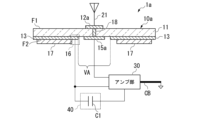
- FIG. 12 is a cross-sectional view showing an example of the vehicle antenna device 1c of this embodiment. Note that the perspective view of the vehicle antenna device 1c of this embodiment is the same as that of the first embodiment shown in FIG. 12, since the configuration of the antenna cover 22 is the same as that of the first embodiment shown in FIG. 2, illustration thereof is omitted here.
- the vehicle antenna device 1c includes a vehicle glass 10c, an amplifier section 30, and a high-pass filter 40.
- the vehicle glass 10c is, for example, laminated glass.
- the vehicle glass 10c includes two glass substrates 11 (11-1, 11-2), an antenna conductor 12, a conductive film 13a, an intermediate film 14 (14-1, 14-2), and an antenna electrode 15. , a signal electrode 16a and a connection conductor 18a.
- the same reference numerals are given to the same configurations as those of the third embodiment shown in FIG. 11, and the description thereof will be omitted.
- the intermediate film 14 includes an intermediate film 14-1 (first intermediate film) and an intermediate film 14-2 (second intermediate film).
- the intermediate film 14-1 and the intermediate film 14-2 are, for example, a PVB film, an EVA film, a COP film, or the like, and it is preferable to use the same material for the intermediate film 14-1 and the intermediate film 14-2.
- the conductive film 13a is a light control film containing a conductor.
- the conductive film 13a is sandwiched between the intermediate films 14-1 and 14-2.
- the conductive film 13a is shown as a single layer for the sake of convenience, but when the conductive film 13a includes a light control film, the conductive film 13a is a pair of conductive films.
- the conductive film 13a is sandwiched between the intermediate films 14-1 and 14-2.
- the connection conductor 18a of this embodiment is a conductor penetrating through the glass substrate 11-2. The connection conductor 18a electrically and directly connects the conductive film 13a and the signal electrode 16a.
- the conductive film 13a which is a light control film, functions as an AM antenna and as an antenna ground for the antenna 21.
- a signal in the frequency band of FM broadcast waves is input from the antenna electrode 15 (second feeding point) to the FM amplifier 32 of the amplifier section 30 .
- a choke coil 50 is connected to the conductive film 13a, which is a dimming film, in order to prevent leakage of received signals of AM broadcast waves.
- the intermediate film 14 includes the intermediate film 14-1 (first intermediate film) and the intermediate film 14-2 (second intermediate film).
- the conductive film 13a is sandwiched between the intermediate films 14-1 and 14-2.
- the conductive film 13a is a light control film containing a conductor.
- the conductive film 13a is arranged between the glass substrate 11-1 (first dielectric substrate) and the glass substrate 11-2 (second dielectric substrate). It is Therefore, for example, even if the conductive film 13a is a light control film, the same effects as in the above-described third embodiment can be obtained. 13a can be used to easily receive AM broadcast waves. Further, according to the vehicle antenna device 1c of the present embodiment, the conductive film 13a, which is a light control film, functions as an antenna ground for the antenna 21. Sufficient antenna gain can be obtained by processing.
- a vehicle antenna device 1d according to a fifth embodiment will be described with reference to the drawings.
- FIG. 13 is a sectional view showing an example of the vehicle antenna device 1d of this embodiment. Note that the perspective view of the vehicle antenna device 1d of this embodiment is the same as that of the first embodiment shown in FIG. 13, since the configuration of the antenna cover 22 is the same as that of the first embodiment shown in FIG. 2, the illustration is omitted here.
- the vehicle antenna device 1d includes a vehicle glass 10d, an amplifier section 30, and a high-pass filter 40.
- the vehicle glass 10d is, for example, laminated glass.
- the vehicle glass 10d includes two glass substrates 11 (11-1, 11-2), an antenna conductor 12, a conductive film 13b, an intermediate film 14, an antenna electrode 15, a signal electrode 16a, and a connection conductor 18a. and
- the same components as those of the third embodiment shown in FIG. 11 are denoted by the same reference numerals, and description thereof will be omitted.
- the conductive film 13b is, for example, a heat ray reflective conductive film (heat ray reflective film) or a low radiation conductive film (Low-E coat).
- the conductive film 13b is arranged between the intermediate film 14 and the glass substrate 11-2 in contact with the third main surface F3 of the glass substrate 11-2.
- the conductive film 13b may be arranged in contact with the fourth main surface F4 of the glass substrate 11-2.
- connection conductor 18a of this embodiment is a conductor penetrating through the glass substrate 11-2.
- the connection conductor 18a electrically and directly connects the conductive film 13b and the signal electrode 16a.
- the conductive film 13b functions as an AM antenna and as an antenna ground for the antenna 21.
- a signal in the AM broadcast wave frequency band received by the conductive film 13b is input to the AM amplifier 31 of the amplifier unit 30 from the signal electrode 16a (first feeding point).
- a signal in the frequency band of FM broadcast waves is input from the antenna electrode 15 (second feeding point) to the FM amplifier 32 of the amplifier section 30 .
- the conductive film 13b is arranged in contact with the third main surface F3 or the fourth main surface F4.
- the conductive film 13b is, for example, a heat ray reflective conductive film (heat ray reflective film) or a low radiation conductive film (Low-E coat).
- the vehicle antenna device 1d of the present embodiment even when the conductive film 13b is arranged in contact with the third main surface F3 or the fourth main surface F4, the third embodiment described above can be used. An effect similar to that of the embodiment can be obtained, and AM broadcast waves can be easily received using the conductive film 13b.
- the conductive film 13b functions as an antenna ground for the antenna 21. Therefore, a sufficient antenna gain can be obtained with respect to the antenna 21 with minimal mechanical processing of the glass substrate 11. can get.
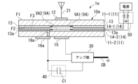
- FIG. 14 is a cross-sectional view showing an example of the vehicle antenna device 1e of this embodiment.
- the perspective view of the vehicle antenna device 1e of this embodiment is the same as that of the first embodiment shown in FIG. 14, the configuration of the antenna cover 22 is the same as that of the first embodiment shown in FIG. 2, so illustration is omitted here.
- a choke coil 50 is connected to the conductive film 13a, which is a dimming film, in order to prevent leakage of received signals of AM broadcast waves, as in the fourth embodiment shown in FIG.
- the vehicle antenna device 1e includes a vehicle glass 10e, an amplifier section 30, and a high-pass filter 40.
- the vehicle glass 10e is, for example, laminated glass.
- the vehicle glass 10e includes two glass substrates 11 (11-1, 11-2), an antenna conductor 12, a conductive film 13 and a conductive film 13a, an intermediate film 14 (14-1, 14-2), It has an antenna electrode 15, a signal electrode 16a, and a connection conductor 18a.
- the same reference numerals are assigned to the same configurations as those of the third and fourth embodiments shown in FIGS. 11 and 12, and the description thereof will be omitted.
- the conductive film 13 is, for example, a conductive film for heat ray reflection (heat ray reflective film).
- the conductive film 13 is arranged in contact with the second main surface F2 of the glass substrate 11-1.
- the sheet resistance value of the conductive film 13 is, for example, lower than the sheet resistance value of the conductive film 13a.
- the conductive film 13a is, for example, a light control film containing a conductor.
- the light control film is a light control film that can electrically change the transmittance of light, and includes, for example, a transparent conductive film such as ITO.
- the conductive film 13a is shown as a single layer for the sake of convenience.
- the conductive film 13a is sandwiched between the intermediate films 14-1 and 14-2.
- the conductive film 13a has second vacant regions VA2 arranged so as to overlap the first vacant regions VA1, which are the vacant regions VA of the conductive film 13, in plan view of the glass substrate 11-1.
- the intermediate film 14 of this embodiment includes an intermediate film 14-1 (first intermediate film) and an intermediate film 14-2 (second intermediate film).
- the intermediate film 14-1 and the intermediate film 14-2 are, for example, a PVB film, an EVA film, a COP film, or the like.
- the connection conductor 18a of this embodiment is a conductor penetrating through the glass substrate 11-2.
- the connection conductor 18a electrically and directly connects the conductive film 13a and the signal electrode 16a.
- the connection conductor 18a may electrically connect the conductive film 13 and the signal electrode 16a directly.
- the conductive film 13 a that is the light control film or the conductive film 13 for heat ray reflection functions as an AM antenna and as an antenna ground for the antenna 21 .
- a signal in the frequency band of the AM broadcast wave received by the conductive film 13a which is a light control film or the conductive film 13 for heat ray reflection is input to the AM amplifier 31 of the amplifier unit 30 from the signal electrode 16a (first feeding point).
- a signal in the frequency band of FM broadcast waves is input from the antenna electrode 15 (second feeding point) to the FM amplifier 32 of the amplifier section 30 .
- the intermediate film 14 includes the intermediate film 14-1 and the intermediate film 14-2, and the conductive films include the conductive film 13 (first conductive film) and the conductive film 13a (second conductive film).
- the conductive film 13 and the conductive film 13a are located on the second main surface F2, between the intermediate films 14-1 and 14-2, on the third main surface F3, and on the fourth main surface F4. They are arranged at two of the upper positions, and arranged in order from the one closest to the glass substrate 11-1.
- the conductive film 13a has a second hole area VA2 arranged so as to overlap the first hole area VA1, which is the hole area VA of the conductive film 13, in plan view of the glass substrate 11-1.
- the vehicle antenna device 1e of the present embodiment even when both the conductive film 13 and the conductive film 13a are provided, the same effects as in the above-described third embodiment can be obtained.
- the conductive film 13 can be used to easily receive AM broadcast waves.
- the conductive film 13a or the conductive film 13 functions as an antenna ground for the antenna 21. Therefore, the minimum mechanical processing of the glass substrate 11 for the antenna 21 is sufficient. antenna gain is obtained.
- the conductive film 13 is arranged in contact with the second main surface F2, and the conductive film 13a is sandwiched between the intermediate films 14-1 and 14-2.
- the conductive film 13 is, for example, a conductor for heat ray reflection (heat ray reflective film), and the conductive film 13a is, for example, a light control film containing a conductor.
- the vehicle antenna device 1e of the present embodiment can easily receive AM broadcast waves even when it includes both a conductor for heat ray reflection (heat ray reflective film) and a light control film, for example. .
- a vehicle antenna device 1f of a seventh embodiment will be described with reference to the drawings.
- a modified example in which laminated glass is used and both a conductive film 13a as a light control film and a conductive film 13c as a conductor for a low-emissivity film (Low-E coat) are provided will be described.
- FIG. 15 is a cross-sectional view showing an example of the vehicle antenna device 1f of this embodiment. Note that the perspective view of the vehicle antenna device 1f of this embodiment is the same as that of the first embodiment shown in FIG. 15, the configuration of the antenna cover 22 is the same as that of the first and fourth embodiments shown in FIGS. 2 and 12, so illustration is omitted here.
- the vehicle antenna device 1f includes a vehicle glass 10f, an amplifier section 30, and a high-pass filter 40.
- the vehicle glass 10f is, for example, laminated glass.
- the vehicle glass 10f includes two glass substrates 11 (11-1, 11-2), an antenna conductor 12, conductive films 13a and 13c, an intermediate film 14, an antenna electrode 15, and a feeding point 16.
- a choke coil 50 is connected to the conductive film 13a, which is a dimming film, in order to prevent leakage of received signals of AM broadcast waves, as in the fourth embodiment shown in FIG.
- the same reference numerals are given to the same configurations as those of the first and fourth embodiments shown in FIGS. 2 and 12, and the description thereof will be omitted.
- the conductive film 13c is, for example, a conductive film for low radiation (Low-E coat).
- the conductive film 13c is arranged in contact with the fourth main surface F4 of the glass substrate 11-2.
- the Low-E coat is provided on the fourth main surface F4
- the conductive film 13c has third hole regions VA3 arranged so as to overlap with the first hole regions VA1 in plan view of the glass substrate 11-1.
- it is preferable that the outer edge of the first hole area VA1 and the outer edge of the third hole area VA3 are aligned with each other, although some misalignment is permissible.
- the feeding point 16 of this embodiment is a part of the conductive film 13c and is electrically connected to the conductive film 13c.
- the vehicle antenna device 1f can receive AM broadcast waves from the feeding point 16 .
- the feeding point 16 is arranged at the center of the conductive film 13, which is 150 mm or more away from the edge of the glass substrate 11-2 in plan view of the glass substrate 11-2.
- the conductive film 13c which is a conductive film for low radiation (Low-E coat) functions as an AM antenna and as an antenna ground for the antenna 21.
- a signal in the frequency band of FM broadcast waves is input from the antenna electrode 15 (second feeding point) to the FM amplifier 32 of the amplifier section 30 .
- the conductive film 13a (first conductive film) is sandwiched between the intermediate films 14-1 and 14-2.
- Conductive film 13c (second conductive film) is arranged in contact with fourth main surface F4.
- the conductive film 13a is, for example, a light control film containing a conductor.
- the conductive film 13c is a conductor for a low emissivity film (Low-E coat).
- FIG. 16 is a cross-sectional view showing an example of the vehicle antenna device 1g of this embodiment. Note that the perspective view of the vehicle antenna device 1g of this embodiment is the same as that of the first embodiment shown in FIG. Also, in FIG. 16, the configuration of the antenna cover 22 is the same as that of the first embodiment shown in FIG. 2, and therefore illustration thereof is omitted here.
- a vehicle antenna device 1g includes a vehicle glass 10g, an amplifier section 30, and a high-pass filter 40.
- the vehicle glass 10g is, for example, laminated glass.
- a vehicle glass 10g includes two glass substrates 11 (11-1, 11-2), an antenna conductor 12, a conductive film 13, an intermediate film 14, an antenna electrode 15, and a signal electrode 16b.
- This embodiment differs from the above-described third embodiment in that the connection conductor 18a is not provided.
- the same reference numerals are given to the same configurations as those of the third embodiment shown in FIG. 11, and the description thereof will be omitted.
- the signal electrode 16b is arranged so as to be electrically connected to the conductive film 13 by capacitive coupling. That is, the signal electrode 16b is arranged at a position overlapping the conductive film 13 in plan view of the glass substrate 11-2 (11). Further, the signal electrode 16b is formed in a square loop shape in plan view of the glass substrate 11-2 (11). That is, the signal electrode 16b has square outer and inner edges.
- the conductive film 13 functions as an AM antenna and as an antenna ground for the antenna 21 .
- a signal in the frequency band of the AM broadcast wave received by the conductive film 13 is electrically connected to the signal electrode 16b (first feeding point) by capacitive coupling, and is transmitted from the feeding point 16 (first feeding point) to the AM of the amplifier section 30. Input to the amplifier 31 .
- a signal in the frequency band of FM broadcast waves is input from the antenna electrode 15 (second feeding point) to the FM amplifier 32 of the amplifier section 30 .
- the conductive film 13 and the signal electrode 16b are electrically connected by capacitive coupling.
- the vehicle antenna device 1g of the present embodiment extracts the received signal of the AM broadcast wave from the signal electrode 16b (first feeding point) without perforating the glass substrate 11-2 (11).
- the conductive film 13 can be used to receive AM broadcast waves more simply.
- the present invention is not limited to the above embodiments, and can be modified without departing from the gist of the present invention.
- the antenna section 20 is a shark fin antenna
- the antenna section 20 is a shark fin antenna
- the dielectric substrate is the glass substrate 11
- the present invention is not limited to this. It's okay.
- the vehicle glasses 10b to 10g do not include the shielding layer 17, but in the third to eighth embodiments, the shielding layer 17 is provided.
- the shielding layer 17 is not provided. You may do so.
- the capacitor C1 of the high-pass filter 40 is configured by a capacitor element.
- the glass substrate 11 or the like may be used for capacitive coupling to constitute the capacitor C1.
- the capacitor C1 may be configured by utilizing the overlapping of the conductive films 13 (13a, 13b) and the vehicle body BD.
- Filter 40 may also be configured as a bandstop filter.
- a third conductive film (not shown) in contact with the fourth main surface F4 of the glass substrate 11-2 may be provided.
- the third conductive film in contact with the fourth main surface F4 is preferably arranged so as not to contact with the antenna electrode 15 .
- the conductive film 13 which is the first conductive film, is the heat ray reflecting film and the second conductive film.
- a combination in which the conductive film 13a is (a conductor contained in) a light control film and the third conductive film is a Low-E coat can be mentioned.
- the fourth main surface F4 has a Low-E coat, it is preferable to overcoat with an insulating layer so that the Low-E coat is not exposed on the surface.
- the connection conductor 18a may be omitted in FIG.
- the feed point 16 may be provided as part of the Low-E coat, which is the third conductive film (as shown in FIG. 15).
- the vehicle antenna device 1b of the third embodiment shown in FIG. 11 to the vehicle antenna device 1e of the sixth embodiment shown in FIG. may be directly connected by a connecting conductor 18 (connecting conductor as shown in the second embodiment) arranged in the hole.
- a connecting conductor 18 connecting conductor as shown in the second embodiment
Landscapes
- Engineering & Computer Science (AREA)
- Mechanical Engineering (AREA)
- Remote Sensing (AREA)
- Details Of Aerials (AREA)
Priority Applications (2)
| Application Number | Priority Date | Filing Date | Title |
|---|---|---|---|
| JP2023559630A JPWO2023085254A1 (https=) | 2021-11-12 | 2022-11-08 | |
| US18/657,962 US20240291154A1 (en) | 2021-11-12 | 2024-05-08 | Vehicle antenna device |
Applications Claiming Priority (2)
| Application Number | Priority Date | Filing Date | Title |
|---|---|---|---|
| JP2021184698 | 2021-11-12 | ||
| JP2021-184698 | 2021-11-12 |
Related Child Applications (1)
| Application Number | Title | Priority Date | Filing Date |
|---|---|---|---|
| US18/657,962 Continuation US20240291154A1 (en) | 2021-11-12 | 2024-05-08 | Vehicle antenna device |
Publications (1)
| Publication Number | Publication Date |
|---|---|
| WO2023085254A1 true WO2023085254A1 (ja) | 2023-05-19 |
Family
ID=86336092
Family Applications (1)
| Application Number | Title | Priority Date | Filing Date |
|---|---|---|---|
| PCT/JP2022/041507 Ceased WO2023085254A1 (ja) | 2021-11-12 | 2022-11-08 | 車両用アンテナ装置 |
Country Status (3)
| Country | Link |
|---|---|
| US (1) | US20240291154A1 (https=) |
| JP (1) | JPWO2023085254A1 (https=) |
| WO (1) | WO2023085254A1 (https=) |
Cited By (3)
| Publication number | Priority date | Publication date | Assignee | Title |
|---|---|---|---|---|
| CN116661182A (zh) * | 2023-05-24 | 2023-08-29 | 福耀玻璃工业集团股份有限公司 | 车窗玻璃与车辆 |
| WO2025053056A1 (ja) * | 2023-09-07 | 2025-03-13 | 日本板硝子株式会社 | 車両ルーフ用合わせガラス |
| WO2025053058A1 (ja) * | 2023-09-07 | 2025-03-13 | 日本板硝子株式会社 | 車両ルーフ用合わせガラス |
Citations (3)
| Publication number | Priority date | Publication date | Assignee | Title |
|---|---|---|---|---|
| JPS6257413U (https=) * | 1985-09-26 | 1987-04-09 | ||
| JPH0294904A (ja) * | 1988-09-30 | 1990-04-05 | Central Glass Co Ltd | 車両用ガラスアンテナ |
| JPH0640746A (ja) * | 1992-07-22 | 1994-02-15 | Asahi Glass Co Ltd | 自動車用窓ガラス |
-
2022
- 2022-11-08 WO PCT/JP2022/041507 patent/WO2023085254A1/ja not_active Ceased
- 2022-11-08 JP JP2023559630A patent/JPWO2023085254A1/ja active Pending
-
2024
- 2024-05-08 US US18/657,962 patent/US20240291154A1/en active Pending
Patent Citations (3)
| Publication number | Priority date | Publication date | Assignee | Title |
|---|---|---|---|---|
| JPS6257413U (https=) * | 1985-09-26 | 1987-04-09 | ||
| JPH0294904A (ja) * | 1988-09-30 | 1990-04-05 | Central Glass Co Ltd | 車両用ガラスアンテナ |
| JPH0640746A (ja) * | 1992-07-22 | 1994-02-15 | Asahi Glass Co Ltd | 自動車用窓ガラス |
Cited By (3)
| Publication number | Priority date | Publication date | Assignee | Title |
|---|---|---|---|---|
| CN116661182A (zh) * | 2023-05-24 | 2023-08-29 | 福耀玻璃工业集团股份有限公司 | 车窗玻璃与车辆 |
| WO2025053056A1 (ja) * | 2023-09-07 | 2025-03-13 | 日本板硝子株式会社 | 車両ルーフ用合わせガラス |
| WO2025053058A1 (ja) * | 2023-09-07 | 2025-03-13 | 日本板硝子株式会社 | 車両ルーフ用合わせガラス |
Also Published As
| Publication number | Publication date |
|---|---|
| US20240291154A1 (en) | 2024-08-29 |
| JPWO2023085254A1 (https=) | 2023-05-19 |
Similar Documents
| Publication | Publication Date | Title |
|---|---|---|
| WO2023085254A1 (ja) | 車両用アンテナ装置 | |
| JP5805299B2 (ja) | アンテナ構造体用のフラット導体接続部品 | |
| CN103329344B (zh) | 具有重叠透明层和邻近外区的天线元件的窗户组件 | |
| KR960015569B1 (ko) | 슬롯 안테나 | |
| JP7605210B2 (ja) | 車両用窓ガラス及び車両構造 | |
| EP3455900B1 (en) | Connector for antennas, a glazing comprising the connector and an antenna system comprising the connector | |
| CN106463813A (zh) | 机动车天线玻璃板 | |
| JP6743486B2 (ja) | 車両用窓ガラス | |
| US9564674B2 (en) | Window antenna connector with impedance matching | |
| JP7286951B2 (ja) | 車両用窓ガラス及びアンテナ | |
| PL204755B1 (pl) | Szyba antenowa | |
| US20200023718A1 (en) | Window glass for vehicle and window glass device for vehicle | |
| JP7735810B2 (ja) | 車両用窓ガラス及び車両用窓ガラス装置 | |
| CN110137677A (zh) | 车辆用窗玻璃及天线 | |
| JP7736070B2 (ja) | 車両用アンテナ装置 | |
| JP7750297B2 (ja) | 車両用アンテナ装置 | |
| JP2011172281A (ja) | 車両用ガラスアンテナ形成用部品 | |
| JP2020022151A (ja) | 車両用窓ガラス及び車両用窓ガラス装置 | |
| JP2024004452A (ja) | 車両用窓ガラス | |
| JP4788333B2 (ja) | 車両用ガラスアンテナ | |
| JP7750290B2 (ja) | 車両用窓ガラス及び車両用窓ガラス装置 | |
| US12537283B2 (en) | Vehicle antenna device and in-vehicle system | |
| EP3430676B1 (en) | Window assembly with transparent layer and an antenna element | |
| JP2022018233A (ja) | 窓ガラス取り付け構造 | |
| JP2024020774A (ja) | 車両用アンテナ |
Legal Events
| Date | Code | Title | Description |
|---|---|---|---|
| 121 | Ep: the epo has been informed by wipo that ep was designated in this application |
Ref document number: 22892752 Country of ref document: EP Kind code of ref document: A1 |
|
| ENP | Entry into the national phase |
Ref document number: 2023559630 Country of ref document: JP Kind code of ref document: A |
|
| NENP | Non-entry into the national phase |
Ref country code: DE |
|
| 122 | Ep: pct application non-entry in european phase |
Ref document number: 22892752 Country of ref document: EP Kind code of ref document: A1 |